US5569001A - Template used in installing door locks - Google Patents
Template used in installing door locks Download PDFInfo
- Publication number
- US5569001A US5569001A US08/490,239 US49023995A US5569001A US 5569001 A US5569001 A US 5569001A US 49023995 A US49023995 A US 49023995A US 5569001 A US5569001 A US 5569001A
- Authority
- US
- United States
- Prior art keywords
- door
- face
- bore
- template
- edge
- Prior art date
- Legal status (The legal status is an assumption and is not a legal conclusion. Google has not performed a legal analysis and makes no representation as to the accuracy of the status listed.)
- Expired - Lifetime
Links
Images


Classifications
-
- B—PERFORMING OPERATIONS; TRANSPORTING
- B23—MACHINE TOOLS; METAL-WORKING NOT OTHERWISE PROVIDED FOR
- B23B—TURNING; BORING
- B23B47/00—Constructional features of components specially designed for boring or drilling machines; Accessories therefor
- B23B47/28—Drill jigs for workpieces
- B23B47/287—Jigs for drilling plate-like workpieces
-
- Y—GENERAL TAGGING OF NEW TECHNOLOGICAL DEVELOPMENTS; GENERAL TAGGING OF CROSS-SECTIONAL TECHNOLOGIES SPANNING OVER SEVERAL SECTIONS OF THE IPC; TECHNICAL SUBJECTS COVERED BY FORMER USPC CROSS-REFERENCE ART COLLECTIONS [XRACs] AND DIGESTS
- Y10—TECHNICAL SUBJECTS COVERED BY FORMER USPC
- Y10T—TECHNICAL SUBJECTS COVERED BY FORMER US CLASSIFICATION
- Y10T408/00—Cutting by use of rotating axially moving tool
- Y10T408/55—Cutting by use of rotating axially moving tool with work-engaging structure other than Tool or tool-support
- Y10T408/567—Adjustable, tool-guiding jig
Definitions
- the present invention relates to a template used in installing door locks.
- a side bracket is slidably received by a front bracket and the two brackets are aligned for the door width or thickness of the door to be drilled.
- the template permits properly related pilot holes to be drilled into the door edge using the side bracket and the door face using the front bracket.
- Porter-Cable produces a model 511 lock installation kit having a jig which has an adjustment for selecting either a 23/8" or 23/4" back set.
- the jig clamps onto a door having a thickness of from 15/16" to 21/8".
- a thumbscrew is used to center the bushing for drilling a 1" bore on the door jamb center line. Pilot holes are not drilled.
- the jig has drill guides for directly drilling the 1" diameter door jamb bore and the 21/8" diameter door edge through bore.
- the present invention is for a template used in installing door locks. More particularly, the present invention permits the drill guide side bracket and front bracket to be slidably oriented for a specific door thickness and secured or held to the door at a proper height.
- the centered drill guide hole in the side bracket piece is used to drill a pilot hole into the end of the door or door jamb along the door center line.
- the two holes on the front bracket are spaced 23/8" and 23/4" from the side bracket piece. For most locks, these are the two standard back set possibilities.
- a pilot hole is drilled. After the two pilot holes are drilled, the template is removed and, using these two pilot holes, the larger holes for receiving the lock components are drilled.
- the present invention comprises a template for use as a guide to drill two perpendicular holes into a door, having: a side bracket having a door edge engaging portion having a door edge flat face and a door edge opposed face, the door edge engaging portion having two opposed parallel sides, the door edge engaging portion having a door edge bore therethrough, the door edge bore having a door edge bore axis transverse to the door edge flat face; a front bracket having a door face engaging portion and means for slidably receiving the side bracket, the door face engaging portion having a door face flat face and a door face opposed face, the door face engaging portion having at least one door face bore therethrough, the at least one door face bore having a door face bore axis transverse to the door face flat face; the two opposed parallel sides of the door edge engaging portion of the side bracket being slidably received by the means for slidably receiving the side bracket of the front bracket, the door edge flat face and the door face flat face being in a transverse relationship, the door edge bore axis being parallel the door
- the means for slidably receiving the side bracket can include a slide lip and a receiving portion, the slide lip and the door face bore axis being in a parallel relationship, the receiving portion including a pair of parallel portions extending transverse from the slide lip, the pair of parallel portions being spaced apart a first distance, the first distance having a first value approximately equal to the width, the receiving portion further including a pair of inward directed portions, each of the parallel portions terminating in one of the inward directed portions, the inward directed portions being transverse to the parallel portions and parallel to the slide lip, the inward directed portions being spaced from the slide lip a second distance, the second distance having a second value approximately equal to the common thickness.
- the side bracket can includes means for identifying that the desired spaced distance between the door edge bore axis and the door face flat face has a value approximately equal one-half of the specified door thickness.
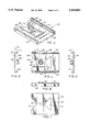
- FIG. 1 is a front left side elevational perspective view of a template used in installing door locks
- FIG. 2 is a perspective view of the side bracket of the template of FIG. 1;
- FIG. 3 is a right end view of the side bracket of FIG. 2;
- FIG. 4 is a front plan view of the side bracket of FIG. 2;
- FIG. 5 is a left end view of the side bracket of FIG. 2;
- FIG. 6 is a bottom end view of the side bracket of FIG. 2;
- FIG. 7 is a back plan view of the side bracket of FIG. 2;
- FIG. 8 is a perspective view of the front bracket of the template of FIG. 1;
- FIG. 9 is a right end view of the front bracket of FIG. 8;
- FIG. 10 is a front plan view of the front bracket of FIG. 8;
- FIG. 11 is a left end view of the front bracket of FIG. 8;
- FIG. 12 is a bottom end view of the front bracket of FIG. 8;
- FIG. 13 is a back plan view of the front bracket of FIG. 8.
- FIG. 1 shows the template 10 having a side bracket 20 and a front bracket 50.
- FIGS. 2-7 provide detail on the side bracket 20 and FIGS. 8-13 provide detail on the front bracket 50.
- the brackets 20/50 are preferably plastic and injection molded.
- Side bracket 20 is shown having a door edge engaging portion 22 having a pair of parallel opposed rails 40 therealong.
- Portion 22 has a flat face 24, which engages the door edge, and an opposed face 26.
- Face 26 has a central raised portion 28 having a bore 30 therethrough, bore 30 having an axis perpendicular to face 24 and extending through bracket 20.
- Bracket 20 is to be placed on the door edge so that bore 30 is at about the door edge midpoint.
- a triangular opening 32 and opposed triangular indentation 34 are provided through bracket 20.
- a first door thickness guide line 36 and a second door thickness guide line 38 are provided.
- guide line 36 has a length of 13/4 inch, which can be designated on bracket 20 as indicia 37.
- guide line 38 has a length of 13/8 inch, which can be designated on bracket 20 as indicia 39. These lengths were selected because these are two standard door widths.
- bracket 20 In use, for example with a vertically mounted door 13/4 inch wide, bracket 20 will be placed against the door edge, line 36 will be horizontal and the end of line 36 at triangle 32 and the end of line 36 at triangle 34 will align with the intersection of the door edge with the two door faces.
- the end of line 36 at triangle 32 terminates at and is perpendicular to a plane extending from front bracket 50's flat face 54, explained hereinafter.
- Front bracket 50 is shown having a door face engaging portion 52 and a C-shaped side bracket receiving portion 66.
- Portion 52 has a flat face 54, which engages a door face, and an opposed face 56.
- Face 56 has a raised portion 58 having a first bore 60 therethrough, bore 60 having an axis perpendicular to face 54 and extending through bracket 50.
- Raised portion 58 can also have a second bore 62 therethrough, bore 62 would also have an axis perpendicular to face 54 and extend through bracket 50.
- Bores 60/62 are used to drill a pilot hole for the lock back set. Two bores 60/62 are provided for the general 23/8" or 23/4" back set.
- bracket receiving portion 66 When side bracket 20 is received into bracket receiving portion 66, the distance from bore 60 to flat face 24 is 23/4", as may be indicated by indicia 61, shown in FIG. 10. Likewise, the distance from bore 62 to flat face 24 is 23/8", as may be indicated by indicia 63, also shown in FIG. 10. A lip 64 is provided.
- C-shaped side bracket receiving portion 66 provides means for slidably receiving bracket 20 therein and retaining faces 24 and 54 in a transverse relationship.
- Portion 66 has a slide lip 68 on which face 24 will slide.
- Rail receiving channels 70 extend from lip 68 away from bores 60/62. Channels 70 have parallel portions 72 extending transverse from lip 68 and inward portions 74 which point at each other to complete the channels 70 which will slidably receive rails 40 of bracket 20.
- brackets 20/50 of template 10 are aligned for use on a 13/8 inch thick door, bracket 20 being received by portion 66 so that the end of line 38 in triangular opening 32 intersects a planar extension of flat face 54.
- Template 10 is placed on the door at a desired height and pilot holes drilled using bore 30 and either bore 60 or 62, depending on the required back set. Template 10 is removed and the pilot holes are used as guides for drilling the larger holes which receive the lock components.
Abstract
Description
Claims (19)
Priority Applications (1)
| Application Number | Priority Date | Filing Date | Title |
|---|---|---|---|
| US08/490,239 US5569001A (en) | 1995-06-14 | 1995-06-14 | Template used in installing door locks |
Applications Claiming Priority (1)
| Application Number | Priority Date | Filing Date | Title |
|---|---|---|---|
| US08/490,239 US5569001A (en) | 1995-06-14 | 1995-06-14 | Template used in installing door locks |
Publications (1)
| Publication Number | Publication Date |
|---|---|
| US5569001A true US5569001A (en) | 1996-10-29 |
Family
ID=23947212
Family Applications (1)
| Application Number | Title | Priority Date | Filing Date |
|---|---|---|---|
| US08/490,239 Expired - Lifetime US5569001A (en) | 1995-06-14 | 1995-06-14 | Template used in installing door locks |
Country Status (1)
| Country | Link |
|---|---|
| US (1) | US5569001A (en) |
Cited By (23)
| Publication number | Priority date | Publication date | Assignee | Title |
|---|---|---|---|---|
| US6077000A (en) * | 1996-03-27 | 2000-06-20 | Aqualisa Products Limited | Pipework template |
| US6079914A (en) * | 1999-03-11 | 2000-06-27 | Peters; Leroy W. | Universal drill jigs |
| US20040062618A1 (en) * | 2002-08-30 | 2004-04-01 | Trettin David J. | Lockset drilling guide |
| US6732557B1 (en) * | 2002-02-15 | 2004-05-11 | Raymond E. Zehrung | Electrified mortise lock having a solenoid cradle |
| US20040240950A1 (en) * | 2002-08-30 | 2004-12-02 | Trettin David J. | Lockset drilling guide |
| US20050084344A1 (en) * | 2003-10-20 | 2005-04-21 | The Boeing Company | Drill template with integral vacuum attach |
| US20050210690A1 (en) * | 2004-03-29 | 2005-09-29 | Morton Lane M | Door operating hardware installation guide |
| US20050220549A1 (en) * | 2004-04-02 | 2005-10-06 | Thomas Rickey J | Door lock set installation jig |
| US20050220548A1 (en) * | 2004-04-02 | 2005-10-06 | Thomas Rickey J | Door lock set installation jig |
| US20050257389A1 (en) * | 2004-04-17 | 2005-11-24 | Detex Corporation | Installation template for lock and alarm assemblies |
| US20070041800A1 (en) * | 2005-08-17 | 2007-02-22 | Santos Jay P | Door lock installation kit |
| US20070086866A1 (en) * | 2002-08-30 | 2007-04-19 | Matthew Shute | Lockset drilling guide |
| US20070110528A1 (en) * | 2005-11-16 | 2007-05-17 | Walley Chao | Door lockset mounting tool |
| US7421791B2 (en) | 2005-06-01 | 2008-09-09 | Nomis Llc | Apparatus and method for hanging a door |
| US8443523B2 (en) | 2010-04-19 | 2013-05-21 | Techtronic Power Tools Technology Limited | Door lock locating tool kit |
| US9284747B2 (en) | 2013-06-12 | 2016-03-15 | Milwaukee Electric Tool Corporation | Door hardware locating tool |
| US9403219B2 (en) | 2012-08-29 | 2016-08-02 | Techtronic Power Tools Technology Limited | Door lock installation kit |
| US10173269B2 (en) * | 2017-05-24 | 2019-01-08 | Stephen Cattaneo | Three dimensional workpiece support and drill jig alignment device for placement of weight loading channels in the body of a model car |
| FR3072081A1 (en) * | 2017-10-10 | 2019-04-12 | Cryl | DEVICE FOR ASSEMBLING A RIDEL ON A PALLET AND SYSTEM FOR ASSEMBLING RIDELLES ON A CORRESPONDING PALLET |
| ES2715645A1 (en) * | 2017-12-05 | 2019-06-05 | Ojmar Sa | TROLLEY LOCK WITH EXTERIOR ACTIVATION ELEMENT (Machine-translation by Google Translate, not legally binding) |
| US10835966B1 (en) | 2019-08-15 | 2020-11-17 | Tech-Tool Sourcing Company Limited | Door lock set installation kit |
| USD924664S1 (en) | 2019-05-21 | 2021-07-13 | Nomis Llc | Door lock installation jig |
| US11359404B2 (en) | 2018-11-06 | 2022-06-14 | Milwaukee Electric Tool Corporation | Door hardware locating tool |
Citations (11)
| Publication number | Priority date | Publication date | Assignee | Title |
|---|---|---|---|---|
| US2679174A (en) * | 1950-09-15 | 1954-05-25 | Schlage Lock Co | Boring jig |
| US2804788A (en) * | 1955-09-27 | 1957-09-03 | Albert V Humphrey | Gauge for dowels |
| US2838966A (en) * | 1955-08-26 | 1958-06-17 | Robertson F Campbell | Adjustable doweling jig |
| US3008359A (en) * | 1959-02-25 | 1961-11-14 | Time Saver Sales Inc | Apparatus for boring a hole in a desired directional alignment |
| US4280776A (en) * | 1979-03-07 | 1981-07-28 | Black & Decker Inc. | Apparatus for installation of a door lockset |
| DE3020970A1 (en) * | 1980-06-03 | 1981-12-10 | Emil Lux Gmbh & Co Kg, 5632 Wermelskirchen | Template for drilling aligned dowel bores at 90 deg. - has drill bushes in plates slidably adjustable on two ends of L=shaped guide element |
| US4331411A (en) * | 1980-05-19 | 1982-05-25 | Charles Kessinger | Door lock drill assembly |
| US4445277A (en) * | 1982-10-29 | 1984-05-01 | John Keefe | Universal programmable lock installation device |
| US4893970A (en) * | 1988-04-29 | 1990-01-16 | Becraft Charles E | Hand held drill guide |
| US5116170A (en) * | 1991-02-22 | 1992-05-26 | Best Lock Corporation | Drill jig for preparing a door to receive a cylindrical lock |
| US5222845A (en) * | 1992-06-22 | 1993-06-29 | Goldstein Steven M | Adjustable drill guide for door handles and locks |
-
1995
- 1995-06-14 US US08/490,239 patent/US5569001A/en not_active Expired - Lifetime
Patent Citations (11)
| Publication number | Priority date | Publication date | Assignee | Title |
|---|---|---|---|---|
| US2679174A (en) * | 1950-09-15 | 1954-05-25 | Schlage Lock Co | Boring jig |
| US2838966A (en) * | 1955-08-26 | 1958-06-17 | Robertson F Campbell | Adjustable doweling jig |
| US2804788A (en) * | 1955-09-27 | 1957-09-03 | Albert V Humphrey | Gauge for dowels |
| US3008359A (en) * | 1959-02-25 | 1961-11-14 | Time Saver Sales Inc | Apparatus for boring a hole in a desired directional alignment |
| US4280776A (en) * | 1979-03-07 | 1981-07-28 | Black & Decker Inc. | Apparatus for installation of a door lockset |
| US4331411A (en) * | 1980-05-19 | 1982-05-25 | Charles Kessinger | Door lock drill assembly |
| DE3020970A1 (en) * | 1980-06-03 | 1981-12-10 | Emil Lux Gmbh & Co Kg, 5632 Wermelskirchen | Template for drilling aligned dowel bores at 90 deg. - has drill bushes in plates slidably adjustable on two ends of L=shaped guide element |
| US4445277A (en) * | 1982-10-29 | 1984-05-01 | John Keefe | Universal programmable lock installation device |
| US4893970A (en) * | 1988-04-29 | 1990-01-16 | Becraft Charles E | Hand held drill guide |
| US5116170A (en) * | 1991-02-22 | 1992-05-26 | Best Lock Corporation | Drill jig for preparing a door to receive a cylindrical lock |
| US5222845A (en) * | 1992-06-22 | 1993-06-29 | Goldstein Steven M | Adjustable drill guide for door handles and locks |
Non-Patent Citations (2)
| Title |
|---|
| Porter Cable model 511 cylindrical lock boring jig catalog, page, other info unknown. * |
| Porter-Cable model 511 cylindrical lock boring jig catalog, page, other info unknown. |
Cited By (38)
| Publication number | Priority date | Publication date | Assignee | Title |
|---|---|---|---|---|
| US6077000A (en) * | 1996-03-27 | 2000-06-20 | Aqualisa Products Limited | Pipework template |
| US6079914A (en) * | 1999-03-11 | 2000-06-27 | Peters; Leroy W. | Universal drill jigs |
| US6732557B1 (en) * | 2002-02-15 | 2004-05-11 | Raymond E. Zehrung | Electrified mortise lock having a solenoid cradle |
| US6994498B2 (en) * | 2002-08-30 | 2006-02-07 | Irwin Industrial Tool Company | Lockset drilling guide |
| US20040131435A2 (en) * | 2002-08-30 | 2004-07-08 | Irwin Industrial Tool Company | Lockset drilling guide |
| US20040240950A1 (en) * | 2002-08-30 | 2004-12-02 | Trettin David J. | Lockset drilling guide |
| US20050082848A1 (en) * | 2002-08-30 | 2005-04-21 | Irwin Industrial Tool Company | Lockset drilling guide |
| US6910837B2 (en) | 2002-08-30 | 2005-06-28 | Irwin Industrial Tool Company | Lockset drilling guide |
| US20040062618A1 (en) * | 2002-08-30 | 2004-04-01 | Trettin David J. | Lockset drilling guide |
| US7316527B2 (en) | 2002-08-30 | 2008-01-08 | Irwin Industrial Tool Company | Lockset drilling guide |
| US20070086866A1 (en) * | 2002-08-30 | 2007-04-19 | Matthew Shute | Lockset drilling guide |
| US20050084344A1 (en) * | 2003-10-20 | 2005-04-21 | The Boeing Company | Drill template with integral vacuum attach |
| US8454280B2 (en) | 2003-10-20 | 2013-06-04 | The Boeing Company | Formation of a pattern of holes in a structure |
| US7195429B2 (en) * | 2003-10-20 | 2007-03-27 | The Boeing Company | Drill template with integral vacuum attach |
| US20050210690A1 (en) * | 2004-03-29 | 2005-09-29 | Morton Lane M | Door operating hardware installation guide |
| US6954989B1 (en) | 2004-03-29 | 2005-10-18 | Kennametal Inc. | Door operating hardware installation guide |
| WO2005097385A3 (en) * | 2004-04-02 | 2006-06-22 | Black & Decker Inc | Door lock set installation jig |
| US7073991B2 (en) * | 2004-04-02 | 2006-07-11 | Black & Decker Inc. | Door lock set installation jig |
| US7112014B2 (en) * | 2004-04-02 | 2006-09-26 | Black & Decker Inc. | Door lock set installation jig |
| US20050220549A1 (en) * | 2004-04-02 | 2005-10-06 | Thomas Rickey J | Door lock set installation jig |
| US20050220548A1 (en) * | 2004-04-02 | 2005-10-06 | Thomas Rickey J | Door lock set installation jig |
| US20050257389A1 (en) * | 2004-04-17 | 2005-11-24 | Detex Corporation | Installation template for lock and alarm assemblies |
| US7246449B2 (en) * | 2004-04-17 | 2007-07-24 | Detex Corporation | Installation template for lock and alarm assemblies |
| US7421791B2 (en) | 2005-06-01 | 2008-09-09 | Nomis Llc | Apparatus and method for hanging a door |
| US20070041800A1 (en) * | 2005-08-17 | 2007-02-22 | Santos Jay P | Door lock installation kit |
| US7530770B2 (en) * | 2005-11-16 | 2009-05-12 | Walley Chao | Door lockset mounting tool |
| US20070110528A1 (en) * | 2005-11-16 | 2007-05-17 | Walley Chao | Door lockset mounting tool |
| US8443523B2 (en) | 2010-04-19 | 2013-05-21 | Techtronic Power Tools Technology Limited | Door lock locating tool kit |
| US9403219B2 (en) | 2012-08-29 | 2016-08-02 | Techtronic Power Tools Technology Limited | Door lock installation kit |
| US9284747B2 (en) | 2013-06-12 | 2016-03-15 | Milwaukee Electric Tool Corporation | Door hardware locating tool |
| US9850670B2 (en) | 2013-06-12 | 2017-12-26 | Milwaukee Electric Tool Corporation | Door hardware locating tool |
| US10487519B2 (en) | 2013-06-12 | 2019-11-26 | Milwaukee Electric Tool Corporation | Door hardware locating tool |
| US10173269B2 (en) * | 2017-05-24 | 2019-01-08 | Stephen Cattaneo | Three dimensional workpiece support and drill jig alignment device for placement of weight loading channels in the body of a model car |
| FR3072081A1 (en) * | 2017-10-10 | 2019-04-12 | Cryl | DEVICE FOR ASSEMBLING A RIDEL ON A PALLET AND SYSTEM FOR ASSEMBLING RIDELLES ON A CORRESPONDING PALLET |
| ES2715645A1 (en) * | 2017-12-05 | 2019-06-05 | Ojmar Sa | TROLLEY LOCK WITH EXTERIOR ACTIVATION ELEMENT (Machine-translation by Google Translate, not legally binding) |
| US11359404B2 (en) | 2018-11-06 | 2022-06-14 | Milwaukee Electric Tool Corporation | Door hardware locating tool |
| USD924664S1 (en) | 2019-05-21 | 2021-07-13 | Nomis Llc | Door lock installation jig |
| US10835966B1 (en) | 2019-08-15 | 2020-11-17 | Tech-Tool Sourcing Company Limited | Door lock set installation kit |
Similar Documents
| Publication | Publication Date | Title |
|---|---|---|
| US5569001A (en) | Template used in installing door locks | |
| CN100592966C (en) | Installation template for lock and alarm assemblies | |
| US4715125A (en) | Door lock drilling template | |
| US5114285A (en) | Door drilling template | |
| US4306823A (en) | Boring and routing jig for cylindrical door knob assemblies and the like | |
| US5116170A (en) | Drill jig for preparing a door to receive a cylindrical lock | |
| US4445277A (en) | Universal programmable lock installation device | |
| US7003889B1 (en) | Template for fitting exit hardware on a door | |
| US6193449B1 (en) | Bracket drill template | |
| US5915891A (en) | Drill guide and method for installing a door lock | |
| US6954989B1 (en) | Door operating hardware installation guide | |
| US7481607B2 (en) | Mounting jig assembly for a door latch | |
| US2268930A (en) | Mortising gauge | |
| US5067537A (en) | Fixture for hinge mortise | |
| US4350066A (en) | Cove molding cutting apparatus and attachment | |
| US3559704A (en) | Jig for guiding a router | |
| US4815215A (en) | Universal holding fixture with templates for routing door and door jambs | |
| US4686769A (en) | Marking gauge for use in mounting hinges | |
| US4787432A (en) | Apparatus and method for producing mortise and tenon joints | |
| US5064319A (en) | Hardware installation tool | |
| US5240052A (en) | Precision router guide method and apparatus | |
| US7252463B2 (en) | Double-sided ultra-thin door marking template | |
| US5940979A (en) | Marking template for locating holes for installation of door and drawer hardware | |
| CA1079162A (en) | Tooling jig | |
| US2966815A (en) | Tool for attaching hinges to windows, doors, gates and the like |
Legal Events
| Date | Code | Title | Description |
|---|---|---|---|
| AS | Assignment |
Owner name: CREDO TOOL COMPANY, OREGON Free format text: ASSIGNMENT OF ASSIGNORS INTEREST;ASSIGNORS:BRUTSCHER, DAVID T.;LEET, LEROY R., SR.;REEL/FRAME:007546/0645 Effective date: 19950613 |
|
| STCF | Information on status: patent grant |
Free format text: PATENTED CASE |
|
| FEPP | Fee payment procedure |
Free format text: PAYOR NUMBER ASSIGNED (ORIGINAL EVENT CODE: ASPN); ENTITY STATUS OF PATENT OWNER: LARGE ENTITY |
|
| FPAY | Fee payment |
Year of fee payment: 4 |
|
| FEPP | Fee payment procedure |
Free format text: PAYOR NUMBER ASSIGNED (ORIGINAL EVENT CODE: ASPN); ENTITY STATUS OF PATENT OWNER: LARGE ENTITY Free format text: PAYER NUMBER DE-ASSIGNED (ORIGINAL EVENT CODE: RMPN); ENTITY STATUS OF PATENT OWNER: LARGE ENTITY |
|
| FPAY | Fee payment |
Year of fee payment: 8 |
|
| AS | Assignment |
Owner name: CREDO TECHNOLOGY CORPORATION, DELAWARE Free format text: ASSIGNMENT OF ASSIGNORS INTEREST;ASSIGNOR:ROBERT BOSCH TOOL CORPORATION;REEL/FRAME:014615/0215 Effective date: 20030101 Owner name: ROBERT BOSCH TOOL CORPORATION, KENTUCKY Free format text: COMBINED MERGER AND CHANGE OF NAME;ASSIGNOR:VERMONT AMERICAN CORPORATION;REEL/FRAME:014609/0574 Effective date: 20021227 Owner name: VERMONT AMERICAN CORPORATION, DELAWARE Free format text: MERGER;ASSIGNOR:CREDO TOOL COMPANY;REEL/FRAME:014609/0549 Effective date: 20021227 |
|
| FPAY | Fee payment |
Year of fee payment: 12 |