US5572226A - Spherical antenna pattern(s) from antenna(s) arranged in a two-dimensional plane for use in RFID tags and labels - Google Patents
Spherical antenna pattern(s) from antenna(s) arranged in a two-dimensional plane for use in RFID tags and labels Download PDFInfo
- Publication number
- US5572226A US5572226A US08/422,007 US42200795A US5572226A US 5572226 A US5572226 A US 5572226A US 42200795 A US42200795 A US 42200795A US 5572226 A US5572226 A US 5572226A
- Authority
- US
- United States
- Prior art keywords
- antenna
- antennas
- dipole
- multiple antennas
- axis
- Prior art date
- Legal status (The legal status is an assumption and is not a legal conclusion. Google has not performed a legal analysis and makes no representation as to the accuracy of the status listed.)
- Expired - Lifetime
Links
Images


Classifications
-
- G—PHYSICS
- G01—MEASURING; TESTING
- G01S—RADIO DIRECTION-FINDING; RADIO NAVIGATION; DETERMINING DISTANCE OR VELOCITY BY USE OF RADIO WAVES; LOCATING OR PRESENCE-DETECTING BY USE OF THE REFLECTION OR RERADIATION OF RADIO WAVES; ANALOGOUS ARRANGEMENTS USING OTHER WAVES
- G01S13/00—Systems using the reflection or reradiation of radio waves, e.g. radar systems; Analogous systems using reflection or reradiation of waves whose nature or wavelength is irrelevant or unspecified
- G01S13/74—Systems using reradiation of radio waves, e.g. secondary radar systems; Analogous systems
- G01S13/75—Systems using reradiation of radio waves, e.g. secondary radar systems; Analogous systems using transponders powered from received waves, e.g. using passive transponders, or using passive reflectors
- G01S13/751—Systems using reradiation of radio waves, e.g. secondary radar systems; Analogous systems using transponders powered from received waves, e.g. using passive transponders, or using passive reflectors wherein the responder or reflector radiates a coded signal
- G01S13/758—Systems using reradiation of radio waves, e.g. secondary radar systems; Analogous systems using transponders powered from received waves, e.g. using passive transponders, or using passive reflectors wherein the responder or reflector radiates a coded signal using a signal generator powered by the interrogation signal
-
- G—PHYSICS
- G06—COMPUTING; CALCULATING OR COUNTING
- G06K—GRAPHICAL DATA READING; PRESENTATION OF DATA; RECORD CARRIERS; HANDLING RECORD CARRIERS
- G06K19/00—Record carriers for use with machines and with at least a part designed to carry digital markings
- G06K19/06—Record carriers for use with machines and with at least a part designed to carry digital markings characterised by the kind of the digital marking, e.g. shape, nature, code
- G06K19/067—Record carriers with conductive marks, printed circuits or semiconductor circuit elements, e.g. credit or identity cards also with resonating or responding marks without active components
- G06K19/07—Record carriers with conductive marks, printed circuits or semiconductor circuit elements, e.g. credit or identity cards also with resonating or responding marks without active components with integrated circuit chips
- G06K19/0723—Record carriers with conductive marks, printed circuits or semiconductor circuit elements, e.g. credit or identity cards also with resonating or responding marks without active components with integrated circuit chips the record carrier comprising an arrangement for non-contact communication, e.g. wireless communication circuits on transponder cards, non-contact smart cards or RFIDs
-
- G—PHYSICS
- G06—COMPUTING; CALCULATING OR COUNTING
- G06K—GRAPHICAL DATA READING; PRESENTATION OF DATA; RECORD CARRIERS; HANDLING RECORD CARRIERS
- G06K19/00—Record carriers for use with machines and with at least a part designed to carry digital markings
- G06K19/06—Record carriers for use with machines and with at least a part designed to carry digital markings characterised by the kind of the digital marking, e.g. shape, nature, code
- G06K19/067—Record carriers with conductive marks, printed circuits or semiconductor circuit elements, e.g. credit or identity cards also with resonating or responding marks without active components
- G06K19/07—Record carriers with conductive marks, printed circuits or semiconductor circuit elements, e.g. credit or identity cards also with resonating or responding marks without active components with integrated circuit chips
- G06K19/073—Special arrangements for circuits, e.g. for protecting identification code in memory
-
- G—PHYSICS
- G06—COMPUTING; CALCULATING OR COUNTING
- G06K—GRAPHICAL DATA READING; PRESENTATION OF DATA; RECORD CARRIERS; HANDLING RECORD CARRIERS
- G06K19/00—Record carriers for use with machines and with at least a part designed to carry digital markings
- G06K19/06—Record carriers for use with machines and with at least a part designed to carry digital markings characterised by the kind of the digital marking, e.g. shape, nature, code
- G06K19/067—Record carriers with conductive marks, printed circuits or semiconductor circuit elements, e.g. credit or identity cards also with resonating or responding marks without active components
- G06K19/07—Record carriers with conductive marks, printed circuits or semiconductor circuit elements, e.g. credit or identity cards also with resonating or responding marks without active components with integrated circuit chips
- G06K19/077—Constructional details, e.g. mounting of circuits in the carrier
- G06K19/07749—Constructional details, e.g. mounting of circuits in the carrier the record carrier being capable of non-contact communication, e.g. constructional details of the antenna of a non-contact smart card
- G06K19/07766—Constructional details, e.g. mounting of circuits in the carrier the record carrier being capable of non-contact communication, e.g. constructional details of the antenna of a non-contact smart card comprising at least a second communication arrangement in addition to a first non-contact communication arrangement
- G06K19/07767—Constructional details, e.g. mounting of circuits in the carrier the record carrier being capable of non-contact communication, e.g. constructional details of the antenna of a non-contact smart card comprising at least a second communication arrangement in addition to a first non-contact communication arrangement the first and second communication means being two different antennas types, e.g. dipole and coil type, or two antennas of the same kind but operating at different frequencies
-
- H—ELECTRICITY
- H01—ELECTRIC ELEMENTS
- H01Q—ANTENNAS, i.e. RADIO AERIALS
- H01Q1/00—Details of, or arrangements associated with, antennas
- H01Q1/12—Supports; Mounting means
- H01Q1/22—Supports; Mounting means by structural association with other equipment or articles
-
- H—ELECTRICITY
- H01—ELECTRIC ELEMENTS
- H01Q—ANTENNAS, i.e. RADIO AERIALS
- H01Q1/00—Details of, or arrangements associated with, antennas
- H01Q1/12—Supports; Mounting means
- H01Q1/22—Supports; Mounting means by structural association with other equipment or articles
- H01Q1/2208—Supports; Mounting means by structural association with other equipment or articles associated with components used in interrogation type services, i.e. in systems for information exchange between an interrogator/reader and a tag/transponder, e.g. in Radio Frequency Identification [RFID] systems
- H01Q1/2225—Supports; Mounting means by structural association with other equipment or articles associated with components used in interrogation type services, i.e. in systems for information exchange between an interrogator/reader and a tag/transponder, e.g. in Radio Frequency Identification [RFID] systems used in active tags, i.e. provided with its own power source or in passive tags, i.e. deriving power from RF signal
-
- H—ELECTRICITY
- H01—ELECTRIC ELEMENTS
- H01Q—ANTENNAS, i.e. RADIO AERIALS
- H01Q1/00—Details of, or arrangements associated with, antennas
- H01Q1/36—Structural form of radiating elements, e.g. cone, spiral, umbrella; Particular materials used therewith
-
- H—ELECTRICITY
- H01—ELECTRIC ELEMENTS
- H01Q—ANTENNAS, i.e. RADIO AERIALS
- H01Q21/00—Antenna arrays or systems
- H01Q21/24—Combinations of antenna units polarised in different directions for transmitting or receiving circularly and elliptically polarised waves or waves linearly polarised in any direction
-
- H—ELECTRICITY
- H01—ELECTRIC ELEMENTS
- H01Q—ANTENNAS, i.e. RADIO AERIALS
- H01Q21/00—Antenna arrays or systems
- H01Q21/28—Combinations of substantially independent non-interacting antenna units or systems
-
- H—ELECTRICITY
- H01—ELECTRIC ELEMENTS
- H01Q—ANTENNAS, i.e. RADIO AERIALS
- H01Q21/00—Antenna arrays or systems
- H01Q21/29—Combinations of different interacting antenna units for giving a desired directional characteristic
-
- H—ELECTRICITY
- H01—ELECTRIC ELEMENTS
- H01Q—ANTENNAS, i.e. RADIO AERIALS
- H01Q3/00—Arrangements for changing or varying the orientation or the shape of the directional pattern of the waves radiated from an antenna or antenna system
- H01Q3/24—Arrangements for changing or varying the orientation or the shape of the directional pattern of the waves radiated from an antenna or antenna system varying the orientation by switching energy from one active radiating element to another, e.g. for beam switching
-
- H—ELECTRICITY
- H02—GENERATION; CONVERSION OR DISTRIBUTION OF ELECTRIC POWER
- H02J—CIRCUIT ARRANGEMENTS OR SYSTEMS FOR SUPPLYING OR DISTRIBUTING ELECTRIC POWER; SYSTEMS FOR STORING ELECTRIC ENERGY
- H02J50/00—Circuit arrangements or systems for wireless supply or distribution of electric power
- H02J50/20—Circuit arrangements or systems for wireless supply or distribution of electric power using microwaves or radio frequency waves
- H02J50/23—Circuit arrangements or systems for wireless supply or distribution of electric power using microwaves or radio frequency waves characterised by the type of transmitting antennas, e.g. directional array antennas or Yagi antennas
-
- H—ELECTRICITY
- H02—GENERATION; CONVERSION OR DISTRIBUTION OF ELECTRIC POWER
- H02J—CIRCUIT ARRANGEMENTS OR SYSTEMS FOR SUPPLYING OR DISTRIBUTING ELECTRIC POWER; SYSTEMS FOR STORING ELECTRIC ENERGY
- H02J50/00—Circuit arrangements or systems for wireless supply or distribution of electric power
- H02J50/20—Circuit arrangements or systems for wireless supply or distribution of electric power using microwaves or radio frequency waves
- H02J50/27—Circuit arrangements or systems for wireless supply or distribution of electric power using microwaves or radio frequency waves characterised by the type of receiving antennas, e.g. rectennas
-
- H—ELECTRICITY
- H04—ELECTRIC COMMUNICATION TECHNIQUE
- H04L—TRANSMISSION OF DIGITAL INFORMATION, e.g. TELEGRAPHIC COMMUNICATION
- H04L61/00—Network arrangements, protocols or services for addressing or naming
- H04L61/35—Network arrangements, protocols or services for addressing or naming involving non-standard use of addresses for implementing network functionalities, e.g. coding subscription information within the address or functional addressing, i.e. assigning an address to a function
-
- H—ELECTRICITY
- H04—ELECTRIC COMMUNICATION TECHNIQUE
- H04L—TRANSMISSION OF DIGITAL INFORMATION, e.g. TELEGRAPHIC COMMUNICATION
- H04L61/00—Network arrangements, protocols or services for addressing or naming
- H04L61/50—Address allocation
- H04L61/5038—Address allocation for local use, e.g. in LAN or USB networks, or in a controller area network [CAN]
-
- H—ELECTRICITY
- H04—ELECTRIC COMMUNICATION TECHNIQUE
- H04L—TRANSMISSION OF DIGITAL INFORMATION, e.g. TELEGRAPHIC COMMUNICATION
- H04L61/00—Network arrangements, protocols or services for addressing or naming
- H04L61/50—Address allocation
- H04L61/5046—Resolving address allocation conflicts; Testing of addresses
-
- H—ELECTRICITY
- H04—ELECTRIC COMMUNICATION TECHNIQUE
- H04L—TRANSMISSION OF DIGITAL INFORMATION, e.g. TELEGRAPHIC COMMUNICATION
- H04L61/00—Network arrangements, protocols or services for addressing or naming
- H04L61/50—Address allocation
- H04L61/5084—Providing for device mobility
-
- G—PHYSICS
- G01—MEASURING; TESTING
- G01S—RADIO DIRECTION-FINDING; RADIO NAVIGATION; DETERMINING DISTANCE OR VELOCITY BY USE OF RADIO WAVES; LOCATING OR PRESENCE-DETECTING BY USE OF THE REFLECTION OR RERADIATION OF RADIO WAVES; ANALOGOUS ARRANGEMENTS USING OTHER WAVES
- G01S13/00—Systems using the reflection or reradiation of radio waves, e.g. radar systems; Analogous systems using reflection or reradiation of waves whose nature or wavelength is irrelevant or unspecified
- G01S13/74—Systems using reradiation of radio waves, e.g. secondary radar systems; Analogous systems
- G01S13/76—Systems using reradiation of radio waves, e.g. secondary radar systems; Analogous systems wherein pulse-type signals are transmitted
- G01S13/765—Systems using reradiation of radio waves, e.g. secondary radar systems; Analogous systems wherein pulse-type signals are transmitted with exchange of information between interrogator and responder
-
- G—PHYSICS
- G01—MEASURING; TESTING
- G01S—RADIO DIRECTION-FINDING; RADIO NAVIGATION; DETERMINING DISTANCE OR VELOCITY BY USE OF RADIO WAVES; LOCATING OR PRESENCE-DETECTING BY USE OF THE REFLECTION OR RERADIATION OF RADIO WAVES; ANALOGOUS ARRANGEMENTS USING OTHER WAVES
- G01S13/00—Systems using the reflection or reradiation of radio waves, e.g. radar systems; Analogous systems using reflection or reradiation of waves whose nature or wavelength is irrelevant or unspecified
- G01S13/74—Systems using reradiation of radio waves, e.g. secondary radar systems; Analogous systems
- G01S13/76—Systems using reradiation of radio waves, e.g. secondary radar systems; Analogous systems wherein pulse-type signals are transmitted
- G01S13/767—Responders; Transponders
-
- H—ELECTRICITY
- H02—GENERATION; CONVERSION OR DISTRIBUTION OF ELECTRIC POWER
- H02J—CIRCUIT ARRANGEMENTS OR SYSTEMS FOR SUPPLYING OR DISTRIBUTING ELECTRIC POWER; SYSTEMS FOR STORING ELECTRIC ENERGY
- H02J50/00—Circuit arrangements or systems for wireless supply or distribution of electric power
- H02J50/40—Circuit arrangements or systems for wireless supply or distribution of electric power using two or more transmitting or receiving devices
-
- H—ELECTRICITY
- H04—ELECTRIC COMMUNICATION TECHNIQUE
- H04L—TRANSMISSION OF DIGITAL INFORMATION, e.g. TELEGRAPHIC COMMUNICATION
- H04L2101/00—Indexing scheme associated with group H04L61/00
- H04L2101/60—Types of network addresses
- H04L2101/604—Address structures or formats
-
- H—ELECTRICITY
- H04—ELECTRIC COMMUNICATION TECHNIQUE
- H04L—TRANSMISSION OF DIGITAL INFORMATION, e.g. TELEGRAPHIC COMMUNICATION
- H04L2101/00—Indexing scheme associated with group H04L61/00
- H04L2101/60—Types of network addresses
- H04L2101/618—Details of network addresses
- H04L2101/622—Layer-2 addresses, e.g. medium access control [MAC] addresses
Definitions
- This invention relates generally to the field of radio frequency transceiver systems and in particular to radio frequency identification (RFID) devices (or tags). More specifically, a nearly spherical antenna pattern is developed from multiple antennas in a two-dimensional plane as well as an antenna switching method to utilize the multiple antennas.
- RFID radio frequency identification
- the field of RFID systems has evolved over the past years from systems developed in relatively large packages (size of a cigarette package) containing battery powered transmission/receiving circuitry or transceiver, such as the identification system disclosed in U.S. Pat. No. 4,274,083, to passive systems (the size of a credit card) in which the transceiver receives its power from the base station or interrogator, such as the identification system disclosed in U.S. Pat. No. 4,654,658.
- U.S. Pat. No. 4,724,427 discloses a passive RFID transceiver as well as a hybrid battery operated version which addresses both types of RFID systems.
- the memory used in RFID systems depends on the type of system used wherein, most passive systems use a programmable read only memory (PROM) of some sort that will retain its programmed data even when power is disrupted or removed while a battery backed system may use any memory type, including random access memory (RAM), that requires a continuous power source to retain programmed data.
- PROM programmable read only memory
- RAM random access memory
- an RFID system may vary in transceiver type, the memory used and circuitry configuration, all RFID systems have a common characteristic: that being a receive/send antenna(s) component.
- the present invention discloses the development of a three-dimensional spherical antenna pattern that is constructed from elements arranged in a two-dimensional plane, a method for switching to various antenna elements and passive recharging of secondary battery cell(s) powering RFID transceiver tags, each of which will allow improved operation of compatible RFID systems that will readily be recognized by one skilled in the art in accordance with the present invention described herein. Also, all U.S. Patents cited herein are hereby incorporated by reference.
- the present invention introduces an RFID system that comprises a two-dimensional antenna configuration that can create a three-dimensional spherical antenna pattern, an antenna switching method and a method to utilize an RF signal for trickle charging passive battery cells resident in the tag transceiver unit.
- the two-dimensional antenna configuration is composed of a combination of one or two dipole antennas and/or a single loop antenna. If two dipoles are used it is preferred to have them arranged such that their axes at approximately a 90° angle to one another. If a dipole and a loop are used, any desired antenna orientation in the plane may be selected. It is well known that a simple dipole antenna driven by an RF voltage source produces a toroidal shaped electromagnetic field centered about the dipole axis.
- a nearly spherical antenna pattern results while the physical elements exist essentially in a two-dimensional plane.
- the pattern is further filled in and the antennas remain in the two-dimensional plane.
- the tag transceiver unit now consists of multiple antennas, it also allows for a method to switch among the multiple antennas to find the antenna or combination of antennas that create(s) the strongest RF communication link thereby enabling more efficient transmitted power or more directional reception coverage. Improving efficiency can be further improved by taking this concept one step further by adding multiple antennas into the interrogator unit. Now the possibility exists whereby the best RF communication possible can be established between the interrogator and transceiver units by switching to the best antenna combination that would most efficiently pass an RF signal between the interrogator and the transceiver.
- the antenna switching concept would work by having multiple antennas in either the interrogator unit or the tag transceiver unit or both.
- the presence of multiple antennas creates an additional advantage in that when the antennas are not being used for communication, they are now free to be used for trickle charging the chargeable battery cell(s) that reside in the transceiver unit.
- each antenna combination has a different efficiency due to different orientations of polarizations, and is also helpful in minimizing the effects of multipath interference.
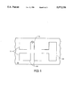
- FIG. 1 shows a planar top view of an RFID transceiver unit containing two dipole antennas in combination with a loop antenna and a signal source or receiver;
- FIGS. 2a-2c depict examples of some of the possible antenna configurations that, when positioned in place of the dipoles and oriented with a loop antenna as shown in FIG. 1, will provide spherical antenna pattern coverage;
- FIGS. 3a and 3b depict multiple antenna variations for use in a RFID system so that when contained in either the interrogator unit and/or tag transceiver unit, antenna switching is possible.
- FIGS. 1 through FIGS. 3a and 3b Several concepts are intertwined in the drawings depicted in FIGS. 1 through FIGS. 3a and 3b as will be described hereinafter.
- dipole antennas 11 and 12 have been processed onto substrate 10 which contains an RFID tag transceiver unit.
- Dipole antennas 11 and 12 have been processed onto substrate 10 at approximately 90° angles to one another.
- Loop antenna 13 has also been processed onto substrate 10 at approximately a 90° to the axis of antenna 12.
- RF source 14 has also been processed onto substrate 10 to represent a signal source or a receiver input depending on the mode of operation the transceiver unit is in.
- the particular antenna configuration depicted in FIG. 1 will effectively achieve a nearly spherical electromagnetic field pattern when combined by switching them one at a time to an RF transmitter or receiver.
- This combination of the three antenna patterns reduces or eliminates the lack of field on-axis of the dipole antennas, while using only antenna geometries lying within a two-dimensional plane of substrate 10. Since the combined coverage is approximately spherical, the orientation between the RFID transceiver (or tag) and the interrogator(s) becomes substantially irrelevant. And although the loop is shown in a rectangular layout, it could as well take other forms, such as circular.
- the dipole antennas of FIG. 1 may be replaced by an unlimited number of configurations, such as the antenna configurations presented in FIGS. 2a-2c, with the main stipulation being that to gain the optimum spherical electromagnetic field pattern it is preferred to have any two dipole antennas placed at approximately 90° to one another (however, they need not be if so desired).
- the many antenna configurations that one skilled in the art could come up with and that are arranged in the orientation as depicted in FIG. 1 may provide for a more optimum spherical pattern coverage or for achieving different impedance characteristics.
- the orientation of FIG. 1 is preferred, the intent of the present invention is to construe the concept of obtaining spherical pattern coverage from antennas lying in a two-dimensional plane.
- antenna switching whereby, a higher operating efficiency is obtained by switching mechanically or electrically to the best combination of antennas (or to the single antenna) which presents the strongest RF communication link between interrogator and transceiver units.
- the transceiver unit must contain circuitry capable of interpreting a command to switch and then to switch among the antennas.
- Digital logic could be used in conjunction with memory means, such as Static Random Access Memory (SRAM), Dynamic Random Access (DRAM) or the like.
- SRAM Static Random Access Memory
- DRAM Dynamic Random Access
- the presence of logic and volatile memory will also require a power supply means, such as rechargeable battery cells that are either permanently fabricated onto substrate 10 or separate cells, depending on one skilled in the art's choice of design or as technology progresses.
- an RFID interrogator unit's antenna system now contains multiple antennas 31, 32 and 33.
- the interrogator computer circuitry under software control, switches to its first antenna, for example antenna 31, for transmitting a wake up call to the RFID transceiver's first antenna, say antenna 11 in FIG. 1.
- the transceiver circuitry wakes up and switches among its antennas 11, 12 and 13, thereby memorizing the power from each antenna by storing this information in the transceiver's resident memory.
- the interrogator then switches to its second antenna, say antenna 32, and again the transceiver switches among its antennas 11, 12 and 13, and stores the relative signal strength of each.
- Antenna switching could also be accomplished by having multiple antennas resident in either the interrogator or the transceiver and follow the procedure just described, thereby establishing all possible antenna combinations. It is also conceivable to have other multiple antenna configurations resident in the interrogator unit like the configuration shown in FIG. 3b.
- dipole antennas 34 and 35 are oriented in manner corresponding to transceiver antennas 11 and 12 of FIG. 1.
- loop antenna 36 is oriented in a manner corresponding to transceiver loop antenna 13 of FIG. 1.
- Another advantage of having multiple antennas that allows antenna switching in the transceiver unit is that they are available for the purposes of trickle charging the rechargeable battery resident in the transceiver unit.
Abstract
Description
Claims (5)
Priority Applications (4)
| Application Number | Priority Date | Filing Date | Title |
|---|---|---|---|
| US08/422,007 US5572226A (en) | 1992-05-15 | 1995-04-11 | Spherical antenna pattern(s) from antenna(s) arranged in a two-dimensional plane for use in RFID tags and labels |
| US08/556,818 US5787174A (en) | 1992-06-17 | 1995-11-02 | Remote identification of integrated circuit |
| US08/581,937 US6144916A (en) | 1992-05-15 | 1996-01-02 | Itinerary monitoring system for storing a plurality of itinerary data points |
| US08/584,788 US5719586A (en) | 1992-05-15 | 1996-01-11 | Spherical antenna pattern(s) from antenna(s) arranged in a two-dimensional plane for use in RFID tags and labels |
Applications Claiming Priority (3)
| Application Number | Priority Date | Filing Date | Title |
|---|---|---|---|
| US88450792A | 1992-05-15 | 1992-05-15 | |
| US13769993A | 1993-10-14 | 1993-10-14 | |
| US08/422,007 US5572226A (en) | 1992-05-15 | 1995-04-11 | Spherical antenna pattern(s) from antenna(s) arranged in a two-dimensional plane for use in RFID tags and labels |
Related Parent Applications (2)
| Application Number | Title | Priority Date | Filing Date |
|---|---|---|---|
| US88450792A Continuation | 1992-05-15 | 1992-05-15 | |
| US13769993A Continuation | 1992-05-15 | 1993-10-14 |
Related Child Applications (3)
| Application Number | Title | Priority Date | Filing Date |
|---|---|---|---|
| US08/556,818 Continuation-In-Part US5787174A (en) | 1992-06-17 | 1995-11-02 | Remote identification of integrated circuit |
| US08/581,937 Continuation-In-Part US6144916A (en) | 1992-05-15 | 1996-01-02 | Itinerary monitoring system for storing a plurality of itinerary data points |
| US08/584,788 Continuation US5719586A (en) | 1992-05-15 | 1996-01-11 | Spherical antenna pattern(s) from antenna(s) arranged in a two-dimensional plane for use in RFID tags and labels |
Publications (1)
| Publication Number | Publication Date |
|---|---|
| US5572226A true US5572226A (en) | 1996-11-05 |
Family
ID=46249637
Family Applications (2)
| Application Number | Title | Priority Date | Filing Date |
|---|---|---|---|
| US08/422,007 Expired - Lifetime US5572226A (en) | 1992-05-15 | 1995-04-11 | Spherical antenna pattern(s) from antenna(s) arranged in a two-dimensional plane for use in RFID tags and labels |
| US08/584,788 Expired - Lifetime US5719586A (en) | 1992-05-15 | 1996-01-11 | Spherical antenna pattern(s) from antenna(s) arranged in a two-dimensional plane for use in RFID tags and labels |
Family Applications After (1)
| Application Number | Title | Priority Date | Filing Date |
|---|---|---|---|
| US08/584,788 Expired - Lifetime US5719586A (en) | 1992-05-15 | 1996-01-11 | Spherical antenna pattern(s) from antenna(s) arranged in a two-dimensional plane for use in RFID tags and labels |
Country Status (1)
| Country | Link |
|---|---|
| US (2) | US5572226A (en) |
Cited By (158)
| Publication number | Priority date | Publication date | Assignee | Title |
|---|---|---|---|---|
| EP0817312A2 (en) * | 1996-07-02 | 1998-01-07 | Murata Manufacturing Co., Ltd. | Antenna apparatus |
| US5719586A (en) * | 1992-05-15 | 1998-02-17 | Micron Communications, Inc. | Spherical antenna pattern(s) from antenna(s) arranged in a two-dimensional plane for use in RFID tags and labels |
| WO1999008597A1 (en) | 1997-08-19 | 1999-02-25 | Mendlein John D | Multi-site ultrasound methods and devices, particularly for measurement of fluid regulation |
| WO1999016702A1 (en) | 1997-09-26 | 1999-04-08 | Gilbarco Inc. | Fuel dispensing system with prepayment means linked to a transponder |
| WO1999016703A1 (en) | 1997-09-26 | 1999-04-08 | Gilbarco Inc. | Fueling system with wireless data transfer |
| US5936527A (en) * | 1998-02-10 | 1999-08-10 | E-Tag Systems, Inc. | Method and apparatus for locating and tracking documents and other objects |
| US6013949A (en) * | 1992-08-12 | 2000-01-11 | Micron Technology, Inc. | Miniature Radio Frequency Transceiver |
| US6057803A (en) * | 1996-03-19 | 2000-05-02 | Matsushita Electric Industrial, Co., Ltd. | Antenna apparatus |
| US6078791A (en) * | 1992-06-17 | 2000-06-20 | Micron Communications, Inc. | Radio frequency identification transceiver and antenna |
| US6077106A (en) * | 1997-06-05 | 2000-06-20 | Micron Communications, Inc. | Thin profile battery mounting contact for printed circuit boards |
| US6166638A (en) * | 1998-04-03 | 2000-12-26 | Intermec Ip Corp. | RF/ID transponder with squinted beam radiation pattern using dipole-over-ground plane antenna |
| US6169938B1 (en) | 1995-12-08 | 2001-01-02 | Marconi Commerce Systems Inc. | Transponder communication of ORVR presence |
| WO2001022118A2 (en) * | 1999-09-24 | 2001-03-29 | Interlogix, Inc. | System and method for locating radio frequency identification tags using three-phase antenna |
| US6249260B1 (en) | 1999-07-16 | 2001-06-19 | Comant Industries, Inc. | T-top antenna for omni-directional horizontally-polarized operation |
| US6273339B1 (en) | 1999-08-30 | 2001-08-14 | Micron Technology, Inc. | Tamper resistant smart card and method of protecting data in a smart card |
| US20010020198A1 (en) * | 1997-09-26 | 2001-09-06 | Wilson Amy Hetz | Fuel dispensing system for cash customers |
| US6325294B2 (en) * | 1992-06-17 | 2001-12-04 | Micron Technology, Inc. | Method of manufacturing an enclosed transceiver |
| DE10056148A1 (en) * | 2000-11-13 | 2002-05-23 | Infineon Technologies Ag | Contactless data medium has data processing unit and at least two reception antennas for each different transmission region, whereby at least two of the antennas form a unit |
| US6396438B1 (en) | 1999-09-24 | 2002-05-28 | Slc Technologies | System and method for locating radio frequency identification tags using three-phase antenna |
| US6452504B1 (en) | 1999-09-24 | 2002-09-17 | Ge Interlogix, Inc. | System and method for communication with radio frequency identification tags using tow message DFM protocol |
| US6473134B1 (en) | 1996-06-19 | 2002-10-29 | Matsushita Electric Industrial Co., Ltd. | Television receiver that detects electric field information from a received television signal and stabilizes a detected synchronizing signal according to the electric field information |
| US6509217B1 (en) | 1999-10-22 | 2003-01-21 | Damoder Reddy | Inexpensive, reliable, planar RFID tag structure and method for making same |
| US6571151B1 (en) | 1998-03-06 | 2003-05-27 | Russel Dean Leatherman | Wireless nozzle interface for a fuel dispenser |
| US6608594B1 (en) | 1999-10-08 | 2003-08-19 | Matsushita Electric Industrial Co., Ltd. | Antenna apparatus and communication system |
| US6650254B1 (en) | 2000-03-13 | 2003-11-18 | Ergodex | Computer input device with individually positionable and programmable switches |
| US6659949B1 (en) | 1997-08-19 | 2003-12-09 | Philipp Lang | Technique to measure capillary related interstitial fluid using ultra-sonic methods and devices |
| US6661335B1 (en) | 1999-09-24 | 2003-12-09 | Ge Interlogix, Inc. | System and method for locating radio frequency identification tags |
| US20040012496A1 (en) * | 2002-07-17 | 2004-01-22 | Ncr Corporation | Radio frequency identification (RFID) tag and a method of operating an RFID tag |
| US6693511B1 (en) | 1999-09-24 | 2004-02-17 | Ge Interlogix, Inc. | System and method for communicating with dormant radio frequency identification tags |
| US20040049451A1 (en) * | 2001-07-10 | 2004-03-11 | Berardi Michael J. | System and method for payment using radio frequency identification in contact and contactless transactions |
| US20040046663A1 (en) * | 2000-08-11 | 2004-03-11 | Jesser Edward A. | RFID tag assembly and system |
| US6724308B2 (en) | 2000-08-11 | 2004-04-20 | Escort Memory Systems | RFID tracking method and system |
| US20040075607A1 (en) * | 2000-04-26 | 2004-04-22 | Cathey David A. | Automated antenna trim for transmitting and receiving semiconductor devices |
| US6727803B2 (en) | 2001-03-16 | 2004-04-27 | E-Tag Systems, Inc. | Method and apparatus for efficiently querying and identifying multiple items on a communication channel |
| US6753820B2 (en) | 2001-07-31 | 2004-06-22 | Koninklijke Philips Electronics N.V. | Communication station comprising a configuration of loosely coupled antennas |
| US20040132406A1 (en) * | 2003-01-03 | 2004-07-08 | Scott Jeff W. | Tags, wireless communication systems, tag communication methods, and wireless communications methods |
| US6774766B1 (en) | 2000-07-21 | 2004-08-10 | E-Tag Systems, Inc. | Method for efficiently querying and identifying multiple items on a communication channel |
| US20040178912A1 (en) * | 1999-09-02 | 2004-09-16 | Smith Freddie W. | Remote communication devices, radio frequency identification devices, wireless communication systems, wireless communication methods, radio frequency identification device communication methods, and methods of forming a remote communication device |
| US20040232223A1 (en) * | 2001-07-10 | 2004-11-25 | American Express Travel Related Services Company, Inc. | Method and system for smellprint recognition biometrics on a fob |
| US20040236700A1 (en) * | 2001-07-10 | 2004-11-25 | American Express Travel Related Services Company, Inc. | Method and system for keystroke scan recognition biometrics on a fob |
| US20040233038A1 (en) * | 2001-07-10 | 2004-11-25 | American Express Travel Related Services Company, Inc. | Method and system for retinal scan recognition biometrics on a fob |
| US20040249839A1 (en) * | 2003-05-09 | 2004-12-09 | American Express Travel Related Services Company, Inc. | Systems and methods for managing multiple accounts on a rf transaction instrument |
| US20040246099A1 (en) * | 1992-08-12 | 2004-12-09 | Micron Technology, Inc. | Miniature radio frequency transceiver |
| US20040260646A1 (en) * | 2001-07-10 | 2004-12-23 | American Express Travel Related Systems Company, Inc. | System and method for encoding information in magnetic stripe format for use in radio frequency identification transactions |
| US6836254B2 (en) * | 2001-08-10 | 2004-12-28 | Antonis Kalis | Antenna system |
| US20050000787A1 (en) * | 2002-09-19 | 2005-01-06 | Rix Scott M. | Independently positionable and programmable key switches |
| US20050004866A1 (en) * | 2001-07-10 | 2005-01-06 | American Express Travel Related Services Company, Inc. | Systems and methods for providing a RF transaction device operable to store multiple distinct calling card accounts |
| US20050004921A1 (en) * | 2003-05-09 | 2005-01-06 | American Express Travel Related Services Company, Inc. | Systems and methods for providing a rf transaction device operable to store multiple distinct accounts |
| US20050033689A1 (en) * | 2001-07-10 | 2005-02-10 | American Express Travel Related Services Company, Inc. | A system and method for dynamic fob synchronization and personalization |
| US20050033687A1 (en) * | 2001-07-10 | 2005-02-10 | American Express Travel Related Services Company, Inc. | Method and system for auditory emissions recognition biometrics on a fob |
| US20050033688A1 (en) * | 2002-07-09 | 2005-02-10 | American Express Travel Related Services Company, Inc. | Methods and apparatus for a secure proximity integrated circuit card transactions |
| US20050035847A1 (en) * | 2001-07-10 | 2005-02-17 | American Express Travel Related Services Company, Inc. | Systems and methods for providing a rf transaction device for use in a private label transaction |
| US20050035192A1 (en) * | 2000-01-21 | 2005-02-17 | American Express Travel Related Services Company, Inc. | Public/private dual card system and method |
| US20050040994A1 (en) * | 2003-08-22 | 2005-02-24 | Checkpoint Systems, Inc. | Security tag with three dimensional antenna array made from flat stock |
| US20050071231A1 (en) * | 2001-07-10 | 2005-03-31 | American Express Travel Related Services Company, Inc. | System and method for securing rf transactions using a radio frequency identification device including a random number generator |
| WO2005031983A2 (en) * | 2003-09-19 | 2005-04-07 | Giesecke & Devrient Gmbh | Sheet document provided with an electric circuit |
| US20050077604A1 (en) * | 2003-10-13 | 2005-04-14 | Mccain Joseph Harry | Integrated circuit package with laminated power cell having coplanar electrode |
| EP1553576A1 (en) * | 2002-08-09 | 2005-07-13 | Matsushita Electric Industrial Co., Ltd. | Optical disc and remote control device |
| US20050160003A1 (en) * | 2001-07-10 | 2005-07-21 | American Express Travel Related Services Company, Inc. | System and method for incenting rfid transaction device usage at a merchant location |
| US20050238455A1 (en) * | 2004-04-23 | 2005-10-27 | Toteff Thomas S | Dual purpose track for holding wheel chocks and strap clips to tie down dirt bikes to trailers |
| US6971021B1 (en) * | 2000-03-08 | 2005-11-29 | Rainbow Technologies, Inc. | Non-wire contact device application for cryptographic module interfaces |
| US20050270185A1 (en) * | 2004-06-04 | 2005-12-08 | Impinj, Inc. | Decoding with memory in RFID system |
| WO2006016184A2 (en) * | 2004-08-12 | 2006-02-16 | Martin Cotton | Seal arrangement |
| US20060074698A1 (en) * | 2001-07-10 | 2006-04-06 | American Express Travel Related Services Company, Inc. | System and method for providing a rf payment solution to a mobile device |
| US20060074813A1 (en) * | 2001-07-10 | 2006-04-06 | American Express Travel Related Services Company, Inc. | System and method for remotely initializing a rf transaction |
| US20060091225A1 (en) * | 2003-11-04 | 2006-05-04 | Forster Ian J | RFID tag using a surface insensitive antenna structure |
| US20060109125A1 (en) * | 2004-11-08 | 2006-05-25 | Goliath Solutions Llc. | System for RF detection and location determination of merchandising materials in retail environments |
| US20060208080A1 (en) * | 2004-11-05 | 2006-09-21 | Goliath Solutions Llc. | Distributed RFID antenna array utilizing circular polarized helical antennas |
| US20060226864A1 (en) * | 2005-04-06 | 2006-10-12 | Kramer Bradley A | Expeditious and low cost testing of RFID ICs |
| US20060267167A1 (en) * | 2004-10-25 | 2006-11-30 | Mccain Joseph H | Microelectronic device with integrated energy source |
| US20070018904A1 (en) * | 1998-02-04 | 2007-01-25 | Smith Freddie W | Communication devices, communication systems and methods of communicating |
| US20070046542A1 (en) * | 2005-08-29 | 2007-03-01 | Fujitsu Limited | Planar antenna |
| US20070075837A1 (en) * | 1996-07-30 | 2007-04-05 | Tuttle Mark E | Radio frequency data communications device with selectively removable antenna portion and method |
| US20070106414A1 (en) * | 2005-11-04 | 2007-05-10 | Volkswagen Aktiengesellschaft | Method for producing a motor vehicle |
| US7249112B2 (en) | 2002-07-09 | 2007-07-24 | American Express Travel Related Services Company, Inc. | System and method for assigning a funding source for a radio frequency identification device |
| US20070216533A1 (en) * | 2004-03-31 | 2007-09-20 | Impinj, Inc. | RFID tags combining signals received from multiple RF ports |
| US20070273473A1 (en) * | 1997-08-14 | 2007-11-29 | Bates Benjamin G | Wireless communications devices, wireless communications systems, and methods of performing wireless communications with a portable device |
| US20070285256A1 (en) * | 2006-06-09 | 2007-12-13 | Intelleflex Corporation | Rfid systems and methods |
| US20080018466A1 (en) * | 2006-07-20 | 2008-01-24 | Intelleflex Corporation | Self-charging rfid tag with long life |
| US20080024309A1 (en) * | 2006-07-25 | 2008-01-31 | International Business Machines Corporation | Rfid tags suitable for affixing to rectangular corners |
| USRE40137E1 (en) | 1997-05-01 | 2008-03-04 | Micron Technology, Inc. | Methods for forming integrated circuits within substrates |
| US20080088449A1 (en) * | 2004-12-21 | 2008-04-17 | Tagsys, A Corporation Of France | Antenna Arrangement |
| US20080198082A1 (en) * | 2005-05-13 | 2008-08-21 | Fractus, S.A. | Antenna Diversity System and Slot Antenna Component |
| CN100416455C (en) * | 2005-07-20 | 2008-09-03 | 乐金电子(昆山)电脑有限公司 | Digital broadcasting transmitter-receiver for portable computer |
| JP2008250573A (en) * | 2007-03-29 | 2008-10-16 | Brother Ind Ltd | Antenna device and radio tag communication apparatus |
| US20080266192A1 (en) * | 2007-04-26 | 2008-10-30 | Micron Technology, Inc. | Methods and systems of changing antenna polarization |
| US20090015407A1 (en) * | 2007-07-13 | 2009-01-15 | Micron Technology, Inc. | Rifid tags and methods of designing rfid tags |
| WO2009010917A2 (en) * | 2007-07-18 | 2009-01-22 | Nxp B.V. | Method for operating a transponder, an integrated circuit for a transponder, and a reader |
| US20090027168A1 (en) * | 2007-07-26 | 2009-01-29 | Micron Technology, Inc. | Methods and systems of rfid tags using rfid circuits and antennas having unmatched frequency ranges |
| US20090027173A1 (en) * | 2007-07-23 | 2009-01-29 | Forster Ian J | Rfid device wtih control logic, and method |
| US20090058649A1 (en) * | 2007-08-31 | 2009-03-05 | Micron Technology, Inc. | Selectively coupling to feed points of an antenna system |
| US7503480B2 (en) | 2001-07-10 | 2009-03-17 | American Express Travel Related Services Company, Inc. | Method and system for tracking user performance |
| US7528728B2 (en) | 2004-03-29 | 2009-05-05 | Impinj Inc. | Circuits for RFID tags with multiple non-independently driven RF ports |
| US20090121965A1 (en) * | 2007-11-13 | 2009-05-14 | Atmel Corporation | Spherical antenna |
| US7542942B2 (en) | 2001-07-10 | 2009-06-02 | American Express Travel Related Services Company, Inc. | System and method for securing sensitive information during completion of a transaction |
| US20090160717A1 (en) * | 2007-12-19 | 2009-06-25 | Kabushiki Kaisha Toshiba | Antenna device and wireless device |
| WO2009101450A1 (en) * | 2008-02-14 | 2009-08-20 | Isis Innovation Limited | Resonant reflector assembly and method |
| US20090273449A1 (en) * | 2008-05-05 | 2009-11-05 | Keystone Technology Solutions, Llc | RFID Interrogator With Adjustable Signal Characteristics |
| US7616120B1 (en) | 2007-02-28 | 2009-11-10 | Impinj, Inc. | Multiple RF-port modulator for RFID tag |
| US20090278688A1 (en) * | 2008-05-08 | 2009-11-12 | Keystone Technology Solutions, Llc | RFID Devices Using RFID Circuits and Antennas Having Unmatched Frequency Ranges |
| US20090289771A1 (en) * | 2008-05-20 | 2009-11-26 | Keystone Technology Solutions, Llc | RFID Device Using Single Antenna For Multiple Resonant Frequency Ranges |
| US7650314B1 (en) | 2001-05-25 | 2010-01-19 | American Express Travel Related Services Company, Inc. | System and method for securing a recurrent billing transaction |
| US7668750B2 (en) | 2001-07-10 | 2010-02-23 | David S Bonalle | Securing RF transactions using a transactions counter |
| US7667589B2 (en) | 2004-03-29 | 2010-02-23 | Impinj, Inc. | RFID tag uncoupling one of its antenna ports and methods |
| US20100066496A1 (en) * | 2008-09-15 | 2010-03-18 | International Business Machines Corporation | Acoustic wave and radio frequency identification device and method |
| US7690577B2 (en) | 2001-07-10 | 2010-04-06 | Blayn W Beenau | Registering a biometric for radio frequency transactions |
| US7725427B2 (en) | 2001-05-25 | 2010-05-25 | Fred Bishop | Recurrent billing maintenance with radio frequency payment devices |
| US20100134291A1 (en) * | 2008-12-01 | 2010-06-03 | Lavedas Thomas G | Radio frequency identification inlay with improved readability |
| US7746215B1 (en) | 2001-07-10 | 2010-06-29 | Fred Bishop | RF transactions using a wireless reader grid |
| US7768379B2 (en) | 2001-07-10 | 2010-08-03 | American Express Travel Related Services Company, Inc. | Method and system for a travel-related multi-function fob |
| US20100207831A1 (en) * | 2009-02-18 | 2010-08-19 | Wu Huei-Chi | Loop Dipole Antenna Module |
| US7793845B2 (en) | 2004-07-01 | 2010-09-14 | American Express Travel Related Services Company, Inc. | Smartcard transaction system and method |
| US7814332B2 (en) | 2001-07-10 | 2010-10-12 | Blayn W Beenau | Voiceprint biometrics on a payment device |
| US7827106B2 (en) | 2001-07-10 | 2010-11-02 | American Express Travel Related Services Company, Inc. | System and method for manufacturing a punch-out RFID transaction device |
| US7835960B2 (en) | 2000-03-07 | 2010-11-16 | American Express Travel Related Services Company, Inc. | System for facilitating a transaction |
| EP2251934A1 (en) * | 2008-03-03 | 2010-11-17 | Murata Manufacturing Co. Ltd. | Wireless ic device and wireless communication system |
| US7837116B2 (en) | 1999-09-07 | 2010-11-23 | American Express Travel Related Services Company, Inc. | Transaction card |
| US7839285B2 (en) | 1997-08-20 | 2010-11-23 | Round Rock Resarch, LLC | Electronic communication devices, methods of forming electrical communication devices, and communications methods |
| US20100321162A1 (en) * | 2008-02-14 | 2010-12-23 | Isis Innovation Limited | Wireless Backscatter Interrogation of Passive, Resonant Sensor-LC-Tags |
| US20110019830A1 (en) * | 2008-04-01 | 2011-01-27 | Audiodent Israel Ltd. | Antenna Arrangement for a Hearing Instrument |
| EP2287779A1 (en) * | 2001-02-12 | 2011-02-23 | Symbol Technologies, Inc. | RFID tag having multiple antennas |
| US7988038B2 (en) | 2001-07-10 | 2011-08-02 | Xatra Fund Mx, Llc | System for biometric security using a fob |
| US7996324B2 (en) | 2001-07-10 | 2011-08-09 | American Express Travel Related Services Company, Inc. | Systems and methods for managing multiple accounts on a RF transaction device using secondary identification indicia |
| US8001054B1 (en) | 2001-07-10 | 2011-08-16 | American Express Travel Related Services Company, Inc. | System and method for generating an unpredictable number using a seeded algorithm |
| USRE42773E1 (en) | 1992-06-17 | 2011-10-04 | Round Rock Research, Llc | Method of manufacturing an enclosed transceiver |
| USRE43157E1 (en) | 2002-09-12 | 2012-02-07 | Xatra Fund Mx, Llc | System and method for reassociating an account number to another transaction account |
| US8115637B2 (en) | 2008-06-03 | 2012-02-14 | Micron Technology, Inc. | Systems and methods to selectively connect antennas to receive and backscatter radio frequency signals |
| CN101065880B (en) * | 2004-10-12 | 2012-05-16 | Ask股份有限公司 | Non-contact label with Y-shaped omnidirectional antenna |
| US8279042B2 (en) | 2001-07-10 | 2012-10-02 | Xatra Fund Mx, Llc | Iris scan biometrics on a payment device |
| US8289136B2 (en) | 2001-07-10 | 2012-10-16 | Xatra Fund Mx, Llc | Hand geometry biometrics on a payment device |
| US8289164B2 (en) | 2003-12-12 | 2012-10-16 | Semiconductor Energy Laboratory Co., Ltd. | Semiconductor device and manufacturing method thereof |
| US8294552B2 (en) | 2001-07-10 | 2012-10-23 | Xatra Fund Mx, Llc | Facial scan biometrics on a payment device |
| US8311834B1 (en) | 1999-06-10 | 2012-11-13 | Gazdzinski Robert F | Computerized information selection and download apparatus and methods |
| DE10162907B4 (en) * | 2000-12-21 | 2013-01-17 | Lear Corp. | Remote access device with inductive multi-frame antenna |
| US8371503B2 (en) | 2003-12-17 | 2013-02-12 | Robert F. Gazdzinski | Portable computerized wireless payment apparatus and methods |
| EP2570973A1 (en) * | 2011-09-16 | 2013-03-20 | Gemalto SA | Method for establishing wireless communication and associated chip card |
| US8429041B2 (en) | 2003-05-09 | 2013-04-23 | American Express Travel Related Services Company, Inc. | Systems and methods for managing account information lifecycles |
| US20130120797A1 (en) * | 2006-03-09 | 2013-05-16 | Zih Corp. | Rfid uhf stripline antenna-coupler |
| US8538863B1 (en) | 2001-07-10 | 2013-09-17 | American Express Travel Related Services Company, Inc. | System and method for facilitating a transaction using a revolving use account associated with a primary account |
| US8543423B2 (en) | 2002-07-16 | 2013-09-24 | American Express Travel Related Services Company, Inc. | Method and apparatus for enrolling with multiple transaction environments |
| US20130321239A1 (en) * | 2012-05-29 | 2013-12-05 | Aereo, Inc. | Three Dimensional Antenna Array System with Troughs |
| US8635131B1 (en) | 2001-07-10 | 2014-01-21 | American Express Travel Related Services Company, Inc. | System and method for managing a transaction protocol |
| US20140062787A1 (en) * | 2012-08-30 | 2014-03-06 | Nxp B.V. | Antenna structures and methods for omni directional radiation patterns |
| US20140225756A1 (en) * | 2000-10-17 | 2014-08-14 | Ezero Technologies Llc | Wireless control system and method |
| US8812368B1 (en) | 1999-03-01 | 2014-08-19 | West View Research, Llc | Computerized information collection and processing apparatus |
| US20150041540A1 (en) * | 2013-08-06 | 2015-02-12 | Hand Held Products, Inc. | Electrotextile rfid antenna |
| US8960535B2 (en) | 2001-07-10 | 2015-02-24 | Iii Holdings 1, Llc | Method and system for resource management and evaluation |
| US9024719B1 (en) | 2001-07-10 | 2015-05-05 | Xatra Fund Mx, Llc | RF transaction system and method for storing user personal data |
| US9031880B2 (en) | 2001-07-10 | 2015-05-12 | Iii Holdings 1, Llc | Systems and methods for non-traditional payment using biometric data |
| US9129200B2 (en) | 2012-10-30 | 2015-09-08 | Raytheon Corporation | Protection system for radio frequency communications |
| USRE45695E1 (en) | 2003-05-30 | 2015-09-29 | Panasonic Intellectual Property Corporation Of America | Optical disc |
| US9454752B2 (en) | 2001-07-10 | 2016-09-27 | Chartoleaux Kg Limited Liability Company | Reload protocol at a transaction processing entity |
| US9812790B2 (en) | 2014-06-23 | 2017-11-07 | Raytheon Company | Near-field gradient probe for the suppression of radio interference |
| US9861296B2 (en) | 1999-03-01 | 2018-01-09 | West View Research, Llc | Ingestible probe with agent delivery |
| US10204246B1 (en) * | 2011-08-02 | 2019-02-12 | Impinj, Inc. | RFID tags with port-dependent functionality |
| CN110783689A (en) * | 2018-07-25 | 2020-02-11 | 美光科技公司 | Tunable integrated millimeter-wave antenna using laser ablation and/or fuses |
| US11100382B2 (en) | 2017-10-20 | 2021-08-24 | Murata Manufacturing Co., Ltd. | Card-type wireless communication device |
| US11300598B2 (en) | 2018-11-26 | 2022-04-12 | Tom Lavedas | Alternative near-field gradient probe for the suppression of radio frequency interference |
Families Citing this family (52)
| Publication number | Priority date | Publication date | Assignee | Title |
|---|---|---|---|---|
| US6147606A (en) * | 1998-03-26 | 2000-11-14 | Intermec Ip Corp. | Apparatus and method for radio frequency transponder with improved read distance |
| DE19901984A1 (en) * | 1999-01-20 | 2000-08-31 | Anatoli Stobbe | System for the automatic identification of at least one transponder in an electromagnetic field of a base station |
| JP2000295027A (en) * | 1999-02-01 | 2000-10-20 | Supersensor Pty Ltd | Hybrid antenna device used for electronic identification system |
| US8654018B2 (en) * | 2005-04-06 | 2014-02-18 | Vanguard Identificaiton Systems, Inc. | Printed planar RFID element wristbands and like personal identification devices |
| US8585852B2 (en) * | 1999-06-16 | 2013-11-19 | Vanguard Identification Systems, Inc. | Methods of making printed planar radio frequency identification elements |
| US6147662A (en) * | 1999-09-10 | 2000-11-14 | Moore North America, Inc. | Radio frequency identification tags and labels |
| US6478229B1 (en) | 2000-03-14 | 2002-11-12 | Harvey Epstein | Packaging tape with radio frequency identification technology |
| US6819243B2 (en) | 2000-04-03 | 2004-11-16 | Mikko Keskilammi | Method and apparatus for identifying bulk goods, preferably roll-like bulk goods |
| US6480158B2 (en) | 2000-05-31 | 2002-11-12 | Bae Systems Information And Electronic Systems Integration Inc. | Narrow-band, crossed-element, offset-tuned dual band, dual mode meander line loaded antenna |
| US7005968B1 (en) | 2000-06-07 | 2006-02-28 | Symbol Technologies, Inc. | Wireless locating and tracking systems |
| US6359596B1 (en) | 2000-07-28 | 2002-03-19 | Lockheed Martin Corporation | Integrated circuit mm-wave antenna structure |
| FR2812482B1 (en) * | 2000-07-28 | 2003-01-24 | Inside Technologies | PORTABLE ELECTRONIC DEVICE COMPRISING SEVERAL INTEGRATED NON-CONTACT CIRCUITS |
| US6975834B1 (en) | 2000-10-03 | 2005-12-13 | Mineral Lassen Llc | Multi-band wireless communication device and method |
| US6646615B2 (en) * | 2000-12-08 | 2003-11-11 | Lucent Technologies Inc. | Method and apparatus for wireless communication utilizing electrical and magnetic polarization |
| TW478206B (en) * | 2000-12-30 | 2002-03-01 | Hon Hai Prec Ind Co Ltd | Printed microstrip dipole antenna |
| US6424311B1 (en) * | 2000-12-30 | 2002-07-23 | Hon Ia Precision Ind. Co., Ltd. | Dual-fed coupled stripline PCB dipole antenna |
| US20020130817A1 (en) * | 2001-03-16 | 2002-09-19 | Forster Ian J. | Communicating with stackable objects using an antenna array |
| US20040080299A1 (en) * | 2002-04-24 | 2004-04-29 | Forster Ian J. | Energy source recharging device and method |
| AU2003233026A1 (en) * | 2002-04-24 | 2003-11-10 | Marconi Intellectual Property (Us) Inc | Rechargeable interrogation reader device and method |
| WO2003092116A2 (en) * | 2002-04-24 | 2003-11-06 | Marconi Intellectual Property (Us) Inc | Energy source with a slot antenna formed in the body |
| US6700491B2 (en) * | 2002-06-14 | 2004-03-02 | Sensormatic Electronics Corporation | Radio frequency identification tag with thin-film battery for antenna |
| US6888510B2 (en) * | 2002-08-19 | 2005-05-03 | Skycross, Inc. | Compact, low profile, circular polarization cubic antenna |
| DE10320188A1 (en) * | 2003-05-07 | 2004-12-02 | Abb Research Ltd. | Magnetic field generation system |
| US7336243B2 (en) * | 2003-05-29 | 2008-02-26 | Sky Cross, Inc. | Radio frequency identification tag |
| US7005986B2 (en) * | 2003-08-19 | 2006-02-28 | Kardios Corporation | Remote temperature monitoring apparatus |
| US7084605B2 (en) * | 2003-10-29 | 2006-08-01 | University Of Pittsburgh | Energy harvesting circuit |
| US7755484B2 (en) * | 2004-02-12 | 2010-07-13 | Avery Dennison Corporation | RFID tag and method of manufacturing the same |
| US7138919B2 (en) * | 2004-02-23 | 2006-11-21 | Checkpoint Systems, Inc. | Identification marking and method for applying the identification marking to an item |
| US7119685B2 (en) * | 2004-02-23 | 2006-10-10 | Checkpoint Systems, Inc. | Method for aligning capacitor plates in a security tag and a capacitor formed thereby |
| US7704346B2 (en) | 2004-02-23 | 2010-04-27 | Checkpoint Systems, Inc. | Method of fabricating a security tag in an integrated surface processing system |
| US7384496B2 (en) | 2004-02-23 | 2008-06-10 | Checkpoint Systems, Inc. | Security tag system for fabricating a tag including an integrated surface processing system |
| US7116227B2 (en) * | 2004-02-23 | 2006-10-03 | Checkpoint Systems, Inc. | Tag having patterned circuit elements and a process for making same |
| US8099335B2 (en) * | 2004-02-23 | 2012-01-17 | Checkpoint Systems, Inc. | Method and system for determining billing information in a tag fabrication process |
| DE202004007819U1 (en) * | 2004-05-13 | 2005-07-14 | Siemens Ag | Mobile data carrier or read-write device with an antenna arrangement with adjustable characteristics, and associated transport device |
| US20060065740A1 (en) * | 2004-09-24 | 2006-03-30 | Lyons Nicholas P | Low cost user input module |
| US7229024B2 (en) * | 2004-12-16 | 2007-06-12 | International Business Machines Corporation | Collimating signals |
| EP1684382A1 (en) * | 2005-01-19 | 2006-07-26 | Samsung Electronics Co., Ltd. | Small ultra wideband antenna having unidirectional radiation pattern |
| US7515051B2 (en) * | 2005-02-25 | 2009-04-07 | Datalogic Mobile, Inc. | RFID antenna system having reduced orientation sensitivity |
| US10133992B2 (en) * | 2005-04-07 | 2018-11-20 | Mgs Modular Galley Systems Ag | System and method for monitoring manufactured pre-prepared meals |
| US7551144B2 (en) * | 2005-04-29 | 2009-06-23 | Telefonaktiebolaget L M Ericsson (Publ) | Triple polarized clover antenna with dipoles |
| US20060255943A1 (en) * | 2005-05-16 | 2006-11-16 | Psc Scanning, Inc. | Induction charging machine, methods, and system for a data reader |
| US20060267733A1 (en) * | 2005-05-27 | 2006-11-30 | Psc Scanning, Inc. | Apparatus and methods for saving power in RFID readers |
| US7429926B1 (en) * | 2005-07-20 | 2008-09-30 | Xilinx, Inc. | Radio frequency identification (RFID) and programmable logic device (PLD) integration and applications |
| FR2891091B1 (en) * | 2005-09-22 | 2008-01-11 | Commissariat Energie Atomique | OMNIDIRECTIONAL PLANAR ANTENNA AND METHOD OF MANUFACTURE |
| US7956572B2 (en) * | 2005-10-21 | 2011-06-07 | The Regents Of The University Of Colorado, A Body Corporate | Systems and methods for receiving and managing power in wireless devices |
| CN100461201C (en) * | 2006-12-01 | 2009-02-11 | 华南理工大学 | Intelligent RFID reading system anticonflict scheduling method |
| CA2616696A1 (en) * | 2006-12-29 | 2008-06-29 | Vanguard Identification Systems, Inc. | Printed planar rfid element wristbands and like personal identification devices |
| US8031054B2 (en) * | 2007-03-27 | 2011-10-04 | Round Rock Research, Llc | Multi-antenna element systems and related methods |
| US20090001930A1 (en) * | 2007-06-29 | 2009-01-01 | Nokia Corporation | Electronic apparatus and associated methods |
| JP2010114961A (en) * | 2008-11-04 | 2010-05-20 | Sony Corp | Power communication device, power communication system, power communicating method, and program |
| US8068012B2 (en) * | 2009-01-08 | 2011-11-29 | Intelleflex Corporation | RFID device and system for setting a level on an electronic device |
| US8094012B1 (en) | 2009-05-15 | 2012-01-10 | The United States Of America As Represented By The Secretary Of The Navy | Active composite RFID tag for object localization and instruction |
Citations (22)
| Publication number | Priority date | Publication date | Assignee | Title |
|---|---|---|---|---|
| US2256619A (en) * | 1940-06-01 | 1941-09-23 | Rca Corp | Directional antenna |
| US3721990A (en) * | 1971-12-27 | 1973-03-20 | Rca Corp | Physically small combined loop and dipole all channel television antenna system |
| US3727230A (en) * | 1970-11-21 | 1973-04-10 | Sony Corp | Antenna having a combined dipole and loop portion |
| US3859652A (en) * | 1972-06-26 | 1975-01-07 | North American Systems Corp | Method and apparatus for detecting the theft of articles |
| US4016553A (en) * | 1975-06-27 | 1977-04-05 | Knogo Corporation | Article detection system with near field electromagnetic wave control |
| US4260983A (en) * | 1978-01-11 | 1981-04-07 | Tag Radionics Limited | Presence sensing detector and system for detecting a receiver/transmitter device affixed to an article |
| US4274083A (en) * | 1977-12-16 | 1981-06-16 | Eiichi Tomoeda | Apparatus for identifying moving objects |
| US4539660A (en) * | 1980-12-26 | 1985-09-03 | Hitachi, Ltd. | Semiconductor integrated circuit |
| US4572976A (en) * | 1982-12-10 | 1986-02-25 | N.V. Nederlandsche Apparatenfabriek Nedap | Transponder for electromagnetic detection system with non-linear circuit |
| US4646090A (en) * | 1983-08-12 | 1987-02-24 | Rca Corporation | Codeable identifying tag and method of identification thereof |
| US4654658A (en) * | 1984-08-03 | 1987-03-31 | Walton Charles A | Identification system with vector phase angle detection |
| US4656472A (en) * | 1985-01-23 | 1987-04-07 | Walton Charles A | Proximity identification system with power aided identifier |
| US4724427A (en) * | 1986-07-18 | 1988-02-09 | B. I. Incorporated | Transponder device |
| US4730188A (en) * | 1984-02-15 | 1988-03-08 | Identification Devices, Inc. | Identification system |
| US4782342A (en) * | 1986-08-04 | 1988-11-01 | Walton Charles A | Proximity identification system with lateral flux paths |
| US4809009A (en) * | 1988-01-25 | 1989-02-28 | Grimes Dale M | Resonant antenna |
| US4854328A (en) * | 1987-03-23 | 1989-08-08 | Philip Pollack | Animal monitoring telltale and information system |
| US4857893A (en) * | 1986-07-18 | 1989-08-15 | Bi Inc. | Single chip transponder device |
| US4918458A (en) * | 1979-05-30 | 1990-04-17 | Anton Brunner | Secondary radar transponder |
| US5126749A (en) * | 1989-08-25 | 1992-06-30 | Kaltner George W | Individually fed multiloop antennas for electronic security systems |
| US5142292A (en) * | 1991-08-05 | 1992-08-25 | Checkpoint Systems, Inc. | Coplanar multiple loop antenna for electronic article surveillance systems |
| US5448110A (en) * | 1992-06-17 | 1995-09-05 | Micron Communications, Inc. | Enclosed transceiver |
Family Cites Families (5)
| Publication number | Priority date | Publication date | Assignee | Title |
|---|---|---|---|---|
| US5103235A (en) * | 1988-12-30 | 1992-04-07 | Checkpoint Systems, Inc. | Antenna structure for an electronic article surveillance system |
| US5084699A (en) * | 1989-05-26 | 1992-01-28 | Trovan Limited | Impedance matching coil assembly for an inductively coupled transponder |
| US5198826A (en) * | 1989-09-22 | 1993-03-30 | Nippon Sheet Glass Co., Ltd. | Wide-band loop antenna with outer and inner loop conductors |
| US5051726A (en) * | 1990-08-14 | 1991-09-24 | Sensormatic Electronics Corporation | Electronic article surveillance system with antenna array for enhanced field falloff |
| US5572226A (en) * | 1992-05-15 | 1996-11-05 | Micron Technology, Inc. | Spherical antenna pattern(s) from antenna(s) arranged in a two-dimensional plane for use in RFID tags and labels |
-
1995
- 1995-04-11 US US08/422,007 patent/US5572226A/en not_active Expired - Lifetime
-
1996
- 1996-01-11 US US08/584,788 patent/US5719586A/en not_active Expired - Lifetime
Patent Citations (22)
| Publication number | Priority date | Publication date | Assignee | Title |
|---|---|---|---|---|
| US2256619A (en) * | 1940-06-01 | 1941-09-23 | Rca Corp | Directional antenna |
| US3727230A (en) * | 1970-11-21 | 1973-04-10 | Sony Corp | Antenna having a combined dipole and loop portion |
| US3721990A (en) * | 1971-12-27 | 1973-03-20 | Rca Corp | Physically small combined loop and dipole all channel television antenna system |
| US3859652A (en) * | 1972-06-26 | 1975-01-07 | North American Systems Corp | Method and apparatus for detecting the theft of articles |
| US4016553A (en) * | 1975-06-27 | 1977-04-05 | Knogo Corporation | Article detection system with near field electromagnetic wave control |
| US4274083A (en) * | 1977-12-16 | 1981-06-16 | Eiichi Tomoeda | Apparatus for identifying moving objects |
| US4260983A (en) * | 1978-01-11 | 1981-04-07 | Tag Radionics Limited | Presence sensing detector and system for detecting a receiver/transmitter device affixed to an article |
| US4918458A (en) * | 1979-05-30 | 1990-04-17 | Anton Brunner | Secondary radar transponder |
| US4539660A (en) * | 1980-12-26 | 1985-09-03 | Hitachi, Ltd. | Semiconductor integrated circuit |
| US4572976A (en) * | 1982-12-10 | 1986-02-25 | N.V. Nederlandsche Apparatenfabriek Nedap | Transponder for electromagnetic detection system with non-linear circuit |
| US4646090A (en) * | 1983-08-12 | 1987-02-24 | Rca Corporation | Codeable identifying tag and method of identification thereof |
| US4730188A (en) * | 1984-02-15 | 1988-03-08 | Identification Devices, Inc. | Identification system |
| US4654658A (en) * | 1984-08-03 | 1987-03-31 | Walton Charles A | Identification system with vector phase angle detection |
| US4656472A (en) * | 1985-01-23 | 1987-04-07 | Walton Charles A | Proximity identification system with power aided identifier |
| US4724427A (en) * | 1986-07-18 | 1988-02-09 | B. I. Incorporated | Transponder device |
| US4857893A (en) * | 1986-07-18 | 1989-08-15 | Bi Inc. | Single chip transponder device |
| US4782342A (en) * | 1986-08-04 | 1988-11-01 | Walton Charles A | Proximity identification system with lateral flux paths |
| US4854328A (en) * | 1987-03-23 | 1989-08-08 | Philip Pollack | Animal monitoring telltale and information system |
| US4809009A (en) * | 1988-01-25 | 1989-02-28 | Grimes Dale M | Resonant antenna |
| US5126749A (en) * | 1989-08-25 | 1992-06-30 | Kaltner George W | Individually fed multiloop antennas for electronic security systems |
| US5142292A (en) * | 1991-08-05 | 1992-08-25 | Checkpoint Systems, Inc. | Coplanar multiple loop antenna for electronic article surveillance systems |
| US5448110A (en) * | 1992-06-17 | 1995-09-05 | Micron Communications, Inc. | Enclosed transceiver |
Cited By (355)
| Publication number | Priority date | Publication date | Assignee | Title |
|---|---|---|---|---|
| US5719586A (en) * | 1992-05-15 | 1998-02-17 | Micron Communications, Inc. | Spherical antenna pattern(s) from antenna(s) arranged in a two-dimensional plane for use in RFID tags and labels |
| USRE42773E1 (en) | 1992-06-17 | 2011-10-04 | Round Rock Research, Llc | Method of manufacturing an enclosed transceiver |
| US6078791A (en) * | 1992-06-17 | 2000-06-20 | Micron Communications, Inc. | Radio frequency identification transceiver and antenna |
| US6325294B2 (en) * | 1992-06-17 | 2001-12-04 | Micron Technology, Inc. | Method of manufacturing an enclosed transceiver |
| US8018340B2 (en) | 1992-08-12 | 2011-09-13 | Round Rock Research, Llc | System and method to track articles at a point of origin and at a point of destination using RFID |
| US20050285744A1 (en) * | 1992-08-12 | 2005-12-29 | Tuttle John R | Radio frequency identification device and system including automatic sorting machine |
| US6013949A (en) * | 1992-08-12 | 2000-01-11 | Micron Technology, Inc. | Miniature Radio Frequency Transceiver |
| US7746230B2 (en) | 1992-08-12 | 2010-06-29 | Round Rock Research, Llc | Radio frequency identification device and method |
| US20040246099A1 (en) * | 1992-08-12 | 2004-12-09 | Micron Technology, Inc. | Miniature radio frequency transceiver |
| US7158031B2 (en) | 1992-08-12 | 2007-01-02 | Micron Technology, Inc. | Thin, flexible, RFID label and system for use |
| US7265674B2 (en) | 1992-08-12 | 2007-09-04 | Micron Technology, Inc. | Thin flexible, RFID labels, and method and apparatus for use |
| US7649463B2 (en) | 1992-08-12 | 2010-01-19 | Keystone Technology Solutions, Llc | Radio frequency identification device and method |
| US6169938B1 (en) | 1995-12-08 | 2001-01-02 | Marconi Commerce Systems Inc. | Transponder communication of ORVR presence |
| US6057803A (en) * | 1996-03-19 | 2000-05-02 | Matsushita Electric Industrial, Co., Ltd. | Antenna apparatus |
| US6473134B1 (en) | 1996-06-19 | 2002-10-29 | Matsushita Electric Industrial Co., Ltd. | Television receiver that detects electric field information from a received television signal and stabilizes a detected synchronizing signal according to the electric field information |
| EP0817312A3 (en) * | 1996-07-02 | 1999-05-19 | Murata Manufacturing Co., Ltd. | Antenna apparatus |
| EP0817312A2 (en) * | 1996-07-02 | 1998-01-07 | Murata Manufacturing Co., Ltd. | Antenna apparatus |
| US20070075837A1 (en) * | 1996-07-30 | 2007-04-05 | Tuttle Mark E | Radio frequency data communications device with selectively removable antenna portion and method |
| US20080100422A1 (en) * | 1996-07-30 | 2008-05-01 | Tuttle Mark E | Radio Frequency Identification Device Operating Methods, Radio Frequency Identification Device Configuration Methods, and Radio Frequency Identification Devices |
| US7884724B2 (en) | 1996-07-30 | 2011-02-08 | Round Rock Research, Llc | Radio frequency data communications device with selectively removable antenna portion and method |
| US8624711B2 (en) | 1996-07-30 | 2014-01-07 | Round Rock Research, Llc | Radio frequency identification device operating methods, radio frequency identification device configuration methods, and radio frequency identification devices |
| USRE40137E1 (en) | 1997-05-01 | 2008-03-04 | Micron Technology, Inc. | Methods for forming integrated circuits within substrates |
| US6077106A (en) * | 1997-06-05 | 2000-06-20 | Micron Communications, Inc. | Thin profile battery mounting contact for printed circuit boards |
| US20070273473A1 (en) * | 1997-08-14 | 2007-11-29 | Bates Benjamin G | Wireless communications devices, wireless communications systems, and methods of performing wireless communications with a portable device |
| US8232865B2 (en) | 1997-08-14 | 2012-07-31 | Round Rock Research, Llc | Wireless communication devices |
| US7920047B2 (en) | 1997-08-14 | 2011-04-05 | Round Rock Research, Llc | Wireless communications devices, wireless communications systems, and methods of performing wireless communications with a portable device |
| US8130077B2 (en) | 1997-08-14 | 2012-03-06 | Round Rock Research, Llc | Wireless communications devices |
| US20070285207A1 (en) * | 1997-08-14 | 2007-12-13 | Keystone Technology Solutions, Llc | Secure Cargo Transportation System |
| US7777608B2 (en) | 1997-08-14 | 2010-08-17 | Round Rock Research, Llc | Secure cargo transportation system |
| US20070285208A1 (en) * | 1997-08-14 | 2007-12-13 | Keystone Technology Solutions, Llc | Secure Cargo Transportation System |
| US8633800B2 (en) | 1997-08-14 | 2014-01-21 | Round Rock Research, Llc | Methods of configuring and using a wireless communications device |
| US20070285213A1 (en) * | 1997-08-14 | 2007-12-13 | Keystone Technology Solutions, Llc | Secure Cargo Transportation System |
| US6659949B1 (en) | 1997-08-19 | 2003-12-09 | Philipp Lang | Technique to measure capillary related interstitial fluid using ultra-sonic methods and devices |
| WO1999008597A1 (en) | 1997-08-19 | 1999-02-25 | Mendlein John D | Multi-site ultrasound methods and devices, particularly for measurement of fluid regulation |
| US20040127790A1 (en) * | 1997-08-19 | 2004-07-01 | Philipp Lang | Measurement of capillary related interstitial fluid using ultrasound methods and devices |
| US7948382B2 (en) | 1997-08-20 | 2011-05-24 | Round Rock Research, Llc | Electronic communication devices, methods of forming electrical communication devices, and communications methods |
| US7839285B2 (en) | 1997-08-20 | 2010-11-23 | Round Rock Resarch, LLC | Electronic communication devices, methods of forming electrical communication devices, and communications methods |
| US6070156A (en) * | 1997-09-26 | 2000-05-30 | Gilbarco Inc. | Providing transaction estimates in a fueling and retail system |
| US20010020198A1 (en) * | 1997-09-26 | 2001-09-06 | Wilson Amy Hetz | Fuel dispensing system for cash customers |
| US20020062174A1 (en) * | 1997-09-26 | 2002-05-23 | Wilson Amy Hetz | Fuel dispensing system for cash customers |
| US20030200008A1 (en) * | 1997-09-26 | 2003-10-23 | Wilson Amy Hetz | Loyalty rewards for cash customers at a fuel dispensing system. |
| WO1999016702A1 (en) | 1997-09-26 | 1999-04-08 | Gilbarco Inc. | Fuel dispensing system with prepayment means linked to a transponder |
| US7020541B2 (en) | 1997-09-26 | 2006-03-28 | Gilbarco Inc. | Fuel dispensing system for cash customers |
| US7027890B2 (en) | 1997-09-26 | 2006-04-11 | Gilbarco Inc. | Fuel dispensing system for cash customers |
| WO1999016703A1 (en) | 1997-09-26 | 1999-04-08 | Gilbarco Inc. | Fueling system with wireless data transfer |
| US7289877B2 (en) | 1997-09-26 | 2007-10-30 | Gilbarco Inc. | Fuel dispensing system for cash customers |
| US20020107608A1 (en) * | 1997-09-26 | 2002-08-08 | Wilson Amy Hetz | Fuel dispensing system for cash customers |
| US6813609B2 (en) | 1997-09-26 | 2004-11-02 | Gilbarco Inc. | Loyalty rewards for cash customers at a fuel dispensing system |
| US7898389B2 (en) * | 1998-02-04 | 2011-03-01 | Round Rock Research, Llc | Radio frequency identification (RFID) tags and methods of communicating between a radio frequency identification (RFID) tag and an interrogator |
| US20070018904A1 (en) * | 1998-02-04 | 2007-01-25 | Smith Freddie W | Communication devices, communication systems and methods of communicating |
| US5936527A (en) * | 1998-02-10 | 1999-08-10 | E-Tag Systems, Inc. | Method and apparatus for locating and tracking documents and other objects |
| US6127928A (en) * | 1998-02-10 | 2000-10-03 | E-Tag Systems, Inc. | Method and apparatus for locating and tracking documents and other objects |
| US6571151B1 (en) | 1998-03-06 | 2003-05-27 | Russel Dean Leatherman | Wireless nozzle interface for a fuel dispenser |
| US6166638A (en) * | 1998-04-03 | 2000-12-26 | Intermec Ip Corp. | RF/ID transponder with squinted beam radiation pattern using dipole-over-ground plane antenna |
| US9913575B2 (en) | 1999-03-01 | 2018-03-13 | West View Research, Llc | Methods of processing data obtained from medical device |
| US8812368B1 (en) | 1999-03-01 | 2014-08-19 | West View Research, Llc | Computerized information collection and processing apparatus |
| US10973397B2 (en) | 1999-03-01 | 2021-04-13 | West View Research, Llc | Computerized information collection and processing apparatus |
| US10154777B2 (en) | 1999-03-01 | 2018-12-18 | West View Research, Llc | Computerized information collection and processing apparatus and methods |
| US10098568B2 (en) | 1999-03-01 | 2018-10-16 | West View Research, Llc | Computerized apparatus with ingestible probe |
| US10028646B2 (en) | 1999-03-01 | 2018-07-24 | West View Research, Llc | Computerized information collection and processing apparatus |
| US10028645B2 (en) | 1999-03-01 | 2018-07-24 | West View Research, Llc | Computerized information collection and processing apparatus |
| US9861268B2 (en) | 1999-03-01 | 2018-01-09 | West View Research, Llc | Methods of processing data obtained from medical device |
| US9861296B2 (en) | 1999-03-01 | 2018-01-09 | West View Research, Llc | Ingestible probe with agent delivery |
| US9715368B2 (en) | 1999-06-10 | 2017-07-25 | West View Research, Llc | Computerized information and display apparatus with rapid convergence algorithm |
| US8676587B1 (en) | 1999-06-10 | 2014-03-18 | West View Research, Llc | Computerized information and display apparatus and methods |
| US8781839B1 (en) | 1999-06-10 | 2014-07-15 | West View Research, Llc | Computerized information and display apparatus |
| US8311834B1 (en) | 1999-06-10 | 2012-11-13 | Gazdzinski Robert F | Computerized information selection and download apparatus and methods |
| US8719038B1 (en) | 1999-06-10 | 2014-05-06 | West View Research, Llc | Computerized information and display apparatus |
| US9710225B2 (en) | 1999-06-10 | 2017-07-18 | West View Research, Llc | Computerized information and display apparatus with automatic context determination |
| US9709972B2 (en) | 1999-06-10 | 2017-07-18 | West View Research, Llc | Computerized information and display apparatus with remote environment control |
| US6249260B1 (en) | 1999-07-16 | 2001-06-19 | Comant Industries, Inc. | T-top antenna for omni-directional horizontally-polarized operation |
| US6273339B1 (en) | 1999-08-30 | 2001-08-14 | Micron Technology, Inc. | Tamper resistant smart card and method of protecting data in a smart card |
| US20070290807A1 (en) * | 1999-09-02 | 2007-12-20 | Smith Freddie W | Remote Communication Devices, Radio Frequency Identification Devices, Wireless Communication Systems, Wireless Communication Methods, Radio Frequency Identification Device Communication Methods, and Methods of Forming a Remote Communication Device |
| US7969313B2 (en) | 1999-09-02 | 2011-06-28 | Round Rock Research, Llc | Remote communication devices, radio frequency identification devices, wireless communication systems, wireless communication methods, radio frequency identification device communication methods, and methods of forming a remote communication device |
| US7710273B2 (en) | 1999-09-02 | 2010-05-04 | Round Rock Research, Llc | Remote communication devices, radio frequency identification devices, wireless communication systems, wireless communication methods, radio frequency identification device communication methods, and methods of forming a remote communication device |
| US20110025506A1 (en) * | 1999-09-02 | 2011-02-03 | Round Rock Research, Llc | Remote communication devices, radio frequency identification devices, wireless communication systems, wireless communication methods, radio frequency identification device communication methods, and methods of forming a remote communication device |
| US7786872B2 (en) | 1999-09-02 | 2010-08-31 | Round Rock Research, Llc | Remote communication devices, radio frequency identification devices, wireless communication systems, wireless communication methods, radio frequency identification device communication methods, and methods of forming a remote communication device |
| US20040178912A1 (en) * | 1999-09-02 | 2004-09-16 | Smith Freddie W. | Remote communication devices, radio frequency identification devices, wireless communication systems, wireless communication methods, radio frequency identification device communication methods, and methods of forming a remote communication device |
| US8191788B2 (en) | 1999-09-07 | 2012-06-05 | American Express Travel Related Services Company, Inc. | Transaction card |
| US7837116B2 (en) | 1999-09-07 | 2010-11-23 | American Express Travel Related Services Company, Inc. | Transaction card |
| US6396438B1 (en) | 1999-09-24 | 2002-05-28 | Slc Technologies | System and method for locating radio frequency identification tags using three-phase antenna |
| US6693511B1 (en) | 1999-09-24 | 2004-02-17 | Ge Interlogix, Inc. | System and method for communicating with dormant radio frequency identification tags |
| WO2001022118A2 (en) * | 1999-09-24 | 2001-03-29 | Interlogix, Inc. | System and method for locating radio frequency identification tags using three-phase antenna |
| US6452504B1 (en) | 1999-09-24 | 2002-09-17 | Ge Interlogix, Inc. | System and method for communication with radio frequency identification tags using tow message DFM protocol |
| US6661335B1 (en) | 1999-09-24 | 2003-12-09 | Ge Interlogix, Inc. | System and method for locating radio frequency identification tags |
| WO2001022118A3 (en) * | 1999-09-24 | 2001-08-09 | Interlogix Inc | System and method for locating radio frequency identification tags using three-phase antenna |
| US6608594B1 (en) | 1999-10-08 | 2003-08-19 | Matsushita Electric Industrial Co., Ltd. | Antenna apparatus and communication system |
| US6509217B1 (en) | 1999-10-22 | 2003-01-21 | Damoder Reddy | Inexpensive, reliable, planar RFID tag structure and method for making same |
| US20050035192A1 (en) * | 2000-01-21 | 2005-02-17 | American Express Travel Related Services Company, Inc. | Public/private dual card system and method |
| US7172112B2 (en) | 2000-01-21 | 2007-02-06 | American Express Travel Related Services Company, Inc. | Public/private dual card system and method |
| USRE43460E1 (en) | 2000-01-21 | 2012-06-12 | Xatra Fund Mx, Llc | Public/private dual card system and method |
| US8818907B2 (en) | 2000-03-07 | 2014-08-26 | Xatra Fund Mx, Llc | Limiting access to account information during a radio frequency transaction |
| US7835960B2 (en) | 2000-03-07 | 2010-11-16 | American Express Travel Related Services Company, Inc. | System for facilitating a transaction |
| US6971021B1 (en) * | 2000-03-08 | 2005-11-29 | Rainbow Technologies, Inc. | Non-wire contact device application for cryptographic module interfaces |
| US6650254B1 (en) | 2000-03-13 | 2003-11-18 | Ergodex | Computer input device with individually positionable and programmable switches |
| US20050062607A1 (en) * | 2000-04-26 | 2005-03-24 | Cathey David A. | Automated antenna trim for transmitting and receiving semiconductor devices |
| US20070290861A1 (en) * | 2000-04-26 | 2007-12-20 | Micron Technology, Inc. | Automated antenna trim for transmitting and receiving semiconductor devices |
| US7417549B2 (en) | 2000-04-26 | 2008-08-26 | Keystone Technology Solutions, Llc | Automated antenna trim for transmitting and receiving semiconductor devices |
| US20070222611A1 (en) * | 2000-04-26 | 2007-09-27 | Micron Technology, Inc. | Automated antenna trim for transmitting and receiving semiconductor devices |
| US20040075607A1 (en) * | 2000-04-26 | 2004-04-22 | Cathey David A. | Automated antenna trim for transmitting and receiving semiconductor devices |
| US8134467B2 (en) | 2000-04-26 | 2012-03-13 | Round Rock Research, Llc | Automated antenna trim for transmitting and receiving semiconductor devices |
| US7253737B2 (en) | 2000-04-26 | 2007-08-07 | Micron Technology, Inc. | Automated antenna trim for transmitting and receiving semiconductor devices |
| US7812728B2 (en) | 2000-04-26 | 2010-10-12 | Round Rock Research, Llc | Methods and apparatuses for radio frequency identification (RFID) tags configured to allow antenna trim |
| US6806812B1 (en) * | 2000-04-26 | 2004-10-19 | Micron Technology, Inc. | Automated antenna trim for transmitting and receiving semiconductor devices |
| US20080150697A1 (en) * | 2000-07-21 | 2008-06-26 | Moyer Normane E | Method for efficiently querying and identifying multiple items on a communication channel |
| US7289015B2 (en) | 2000-07-21 | 2007-10-30 | Etag Systems, Inc. | Method for efficiently querying and identifying multiple items on a communication channel |
| US7737823B2 (en) | 2000-07-21 | 2010-06-15 | E-Tag Systems, Inc. | Method for efficiently querying and identifying multiple items on a communication channel |
| US20050007240A1 (en) * | 2000-07-21 | 2005-01-13 | Moyer Norman E. | Method for efficiently querying and identifying multiple items on a communication channel |
| US20110057777A1 (en) * | 2000-07-21 | 2011-03-10 | Moyer Norman E | Method for efficiently querying an identifying multiple items on a communication channel |
| US8860554B2 (en) | 2000-07-21 | 2014-10-14 | Etag Systems, Inc. | Deterministic Method for efficiently querying and identifying multiple items on a communication channel |
| US6774766B1 (en) | 2000-07-21 | 2004-08-10 | E-Tag Systems, Inc. | Method for efficiently querying and identifying multiple items on a communication channel |
| US8248213B2 (en) | 2000-07-21 | 2012-08-21 | Etag Systems, Inc. | Deterministic method for efficiently querying and identifying multiple items on a communication channel |
| US20040046663A1 (en) * | 2000-08-11 | 2004-03-11 | Jesser Edward A. | RFID tag assembly and system |
| US6724308B2 (en) | 2000-08-11 | 2004-04-20 | Escort Memory Systems | RFID tracking method and system |
| US7075435B2 (en) | 2000-08-11 | 2006-07-11 | Escort Memory Systems | RFID tag assembly and system |
| US20140225756A1 (en) * | 2000-10-17 | 2014-08-14 | Ezero Technologies Llc | Wireless control system and method |
| DE10056148A1 (en) * | 2000-11-13 | 2002-05-23 | Infineon Technologies Ag | Contactless data medium has data processing unit and at least two reception antennas for each different transmission region, whereby at least two of the antennas form a unit |
| US20040074975A1 (en) * | 2000-11-13 | 2004-04-22 | Harald Gundlach | Contactless data storage medium |
| US6946958B2 (en) | 2000-11-13 | 2005-09-20 | Infineon Technologies Ag | Contactless data storage medium |
| DE10162907B4 (en) * | 2000-12-21 | 2013-01-17 | Lear Corp. | Remote access device with inductive multi-frame antenna |
| US7965189B2 (en) | 2001-02-12 | 2011-06-21 | Symbol Technologies, Inc. | Radio frequency identification architecture |
| EP2287779A1 (en) * | 2001-02-12 | 2011-02-23 | Symbol Technologies, Inc. | RFID tag having multiple antennas |
| US7928843B2 (en) | 2001-02-12 | 2011-04-19 | Symbol Technologies, Inc. | Method, system, and apparatus for communications in a RFID system |
| US7916001B2 (en) | 2001-03-16 | 2011-03-29 | Etag Systems, Inc. | Methods for interrogating objects to be identified over a communications medium |
| US20070222561A1 (en) * | 2001-03-16 | 2007-09-27 | Robert Hulvey | Method and apparatus for efficiently querying and identifying multiple items on a communication channel |
| US20060103505A1 (en) * | 2001-03-16 | 2006-05-18 | Robert Hulvey | Method and apparatus for efficiently querying and identifying multiple items on a communication channel |
| US8451092B2 (en) | 2001-03-16 | 2013-05-28 | Etag Systems, Inc. | Method and apparatus for efficiently querying and identifying multiple items on a communication channel |
| US7173518B2 (en) | 2001-03-16 | 2007-02-06 | E-Tag Systems, Inc. | Method and apparatus for efficiently querying and identifying multiple items on a communication channel |
| US6727803B2 (en) | 2001-03-16 | 2004-04-27 | E-Tag Systems, Inc. | Method and apparatus for efficiently querying and identifying multiple items on a communication channel |
| US6967564B2 (en) | 2001-03-16 | 2005-11-22 | E-Tag Systems, Inc. | Method and apparatus for efficiently querying and identifying multiple items on a communication channel |
| US7725427B2 (en) | 2001-05-25 | 2010-05-25 | Fred Bishop | Recurrent billing maintenance with radio frequency payment devices |
| US7650314B1 (en) | 2001-05-25 | 2010-01-19 | American Express Travel Related Services Company, Inc. | System and method for securing a recurrent billing transaction |
| US7988038B2 (en) | 2001-07-10 | 2011-08-02 | Xatra Fund Mx, Llc | System for biometric security using a fob |
| US7768379B2 (en) | 2001-07-10 | 2010-08-03 | American Express Travel Related Services Company, Inc. | Method and system for a travel-related multi-function fob |
| US8548927B2 (en) | 2001-07-10 | 2013-10-01 | Xatra Fund Mx, Llc | Biometric registration for facilitating an RF transaction |
| US8538863B1 (en) | 2001-07-10 | 2013-09-17 | American Express Travel Related Services Company, Inc. | System and method for facilitating a transaction using a revolving use account associated with a primary account |
| US8635131B1 (en) | 2001-07-10 | 2014-01-21 | American Express Travel Related Services Company, Inc. | System and method for managing a transaction protocol |
| US7228155B2 (en) | 2001-07-10 | 2007-06-05 | American Express Travel Related Services Company, Inc. | System and method for remotely initializing a RF transaction |
| US20040049451A1 (en) * | 2001-07-10 | 2004-03-11 | Berardi Michael J. | System and method for payment using radio frequency identification in contact and contactless transactions |
| US8294552B2 (en) | 2001-07-10 | 2012-10-23 | Xatra Fund Mx, Llc | Facial scan biometrics on a payment device |
| US8289136B2 (en) | 2001-07-10 | 2012-10-16 | Xatra Fund Mx, Llc | Hand geometry biometrics on a payment device |
| US8284025B2 (en) | 2001-07-10 | 2012-10-09 | Xatra Fund Mx, Llc | Method and system for auditory recognition biometrics on a FOB |
| US8279042B2 (en) | 2001-07-10 | 2012-10-02 | Xatra Fund Mx, Llc | Iris scan biometrics on a payment device |
| US8266056B2 (en) | 2001-07-10 | 2012-09-11 | American Express Travel Related Services Company, Inc. | System and method for manufacturing a punch-out RFID transaction device |
| US20060074813A1 (en) * | 2001-07-10 | 2006-04-06 | American Express Travel Related Services Company, Inc. | System and method for remotely initializing a rf transaction |
| US20060074698A1 (en) * | 2001-07-10 | 2006-04-06 | American Express Travel Related Services Company, Inc. | System and method for providing a rf payment solution to a mobile device |
| US7239226B2 (en) * | 2001-07-10 | 2007-07-03 | American Express Travel Related Services Company, Inc. | System and method for payment using radio frequency identification in contact and contactless transactions |
| US7463133B2 (en) | 2001-07-10 | 2008-12-09 | American Express Travel Related Services Company, Inc. | Systems and methods for providing a RF transaction device operable to store multiple distinct calling card accounts |
| US20040232223A1 (en) * | 2001-07-10 | 2004-11-25 | American Express Travel Related Services Company, Inc. | Method and system for smellprint recognition biometrics on a fob |
| US8074889B2 (en) | 2001-07-10 | 2011-12-13 | Xatra Fund Mx, Llc | System for biometric security using a fob |
| US20040236700A1 (en) * | 2001-07-10 | 2004-11-25 | American Express Travel Related Services Company, Inc. | Method and system for keystroke scan recognition biometrics on a fob |
| US7493288B2 (en) | 2001-07-10 | 2009-02-17 | Xatra Fund Mx, Llc | RF payment via a mobile device |
| US9886692B2 (en) | 2001-07-10 | 2018-02-06 | Chartoleaux Kg Limited Liability Company | Securing a transaction between a transponder and a reader |
| US20040233038A1 (en) * | 2001-07-10 | 2004-11-25 | American Express Travel Related Services Company, Inc. | Method and system for retinal scan recognition biometrics on a fob |
| US9881294B2 (en) | 2001-07-10 | 2018-01-30 | Chartoleaux Kg Limited Liability Company | RF payment via a mobile device |
| US7503480B2 (en) | 2001-07-10 | 2009-03-17 | American Express Travel Related Services Company, Inc. | Method and system for tracking user performance |
| US8001054B1 (en) | 2001-07-10 | 2011-08-16 | American Express Travel Related Services Company, Inc. | System and method for generating an unpredictable number using a seeded algorithm |
| US7996324B2 (en) | 2001-07-10 | 2011-08-09 | American Express Travel Related Services Company, Inc. | Systems and methods for managing multiple accounts on a RF transaction device using secondary identification indicia |
| US20110161235A1 (en) * | 2001-07-10 | 2011-06-30 | American Express Travel Related Services Company, Inc. | System and method for securing rf transactions using a radio frequency identification device including a random number generator |
| US20040260646A1 (en) * | 2001-07-10 | 2004-12-23 | American Express Travel Related Systems Company, Inc. | System and method for encoding information in magnetic stripe format for use in radio frequency identification transactions |
| US20090115571A1 (en) * | 2001-07-10 | 2009-05-07 | Xatra Fund Mx, Llc | Rf payment via a mobile device |
| US7542942B2 (en) | 2001-07-10 | 2009-06-02 | American Express Travel Related Services Company, Inc. | System and method for securing sensitive information during completion of a transaction |
| US7925535B2 (en) | 2001-07-10 | 2011-04-12 | American Express Travel Related Services Company, Inc. | System and method for securing RF transactions using a radio frequency identification device including a random number generator |
| US20050004866A1 (en) * | 2001-07-10 | 2005-01-06 | American Express Travel Related Services Company, Inc. | Systems and methods for providing a RF transaction device operable to store multiple distinct calling card accounts |
| US7119659B2 (en) | 2001-07-10 | 2006-10-10 | American Express Travel Related Services Company, Inc. | Systems and methods for providing a RF transaction device for use in a private label transaction |
| US10839388B2 (en) | 2001-07-10 | 2020-11-17 | Liberty Peak Ventures, Llc | Funding a radio frequency device transaction |
| US7059531B2 (en) | 2001-07-10 | 2006-06-13 | American Express Travel Related Services Company, Inc. | Method and system for smellprint recognition biometrics on a fob |
| US7889052B2 (en) | 2001-07-10 | 2011-02-15 | Xatra Fund Mx, Llc | Authorizing payment subsequent to RF transactions |
| US20050160003A1 (en) * | 2001-07-10 | 2005-07-21 | American Express Travel Related Services Company, Inc. | System and method for incenting rfid transaction device usage at a merchant location |
| US8872619B2 (en) | 2001-07-10 | 2014-10-28 | Xatra Fund Mx, Llc | Securing a transaction between a transponder and a reader |
| US7886157B2 (en) | 2001-07-10 | 2011-02-08 | Xatra Fund Mx, Llc | Hand geometry recognition biometrics on a fob |
| US20050033689A1 (en) * | 2001-07-10 | 2005-02-10 | American Express Travel Related Services Company, Inc. | A system and method for dynamic fob synchronization and personalization |
| US8960535B2 (en) | 2001-07-10 | 2015-02-24 | Iii Holdings 1, Llc | Method and system for resource management and evaluation |
| US9024719B1 (en) | 2001-07-10 | 2015-05-05 | Xatra Fund Mx, Llc | RF transaction system and method for storing user personal data |
| US9031880B2 (en) | 2001-07-10 | 2015-05-12 | Iii Holdings 1, Llc | Systems and methods for non-traditional payment using biometric data |
| US9454752B2 (en) | 2001-07-10 | 2016-09-27 | Chartoleaux Kg Limited Liability Company | Reload protocol at a transaction processing entity |
| US7668750B2 (en) | 2001-07-10 | 2010-02-23 | David S Bonalle | Securing RF transactions using a transactions counter |
| US20050033687A1 (en) * | 2001-07-10 | 2005-02-10 | American Express Travel Related Services Company, Inc. | Method and system for auditory emissions recognition biometrics on a fob |
| USRE45615E1 (en) | 2001-07-10 | 2015-07-14 | Xatra Fund Mx, Llc | RF transaction device |
| US7690577B2 (en) | 2001-07-10 | 2010-04-06 | Blayn W Beenau | Registering a biometric for radio frequency transactions |
| US7694876B2 (en) | 2001-07-10 | 2010-04-13 | American Express Travel Related Services Company, Inc. | Method and system for tracking user performance |
| US20050035847A1 (en) * | 2001-07-10 | 2005-02-17 | American Express Travel Related Services Company, Inc. | Systems and methods for providing a rf transaction device for use in a private label transaction |
| US7827106B2 (en) | 2001-07-10 | 2010-11-02 | American Express Travel Related Services Company, Inc. | System and method for manufacturing a punch-out RFID transaction device |
| US7814332B2 (en) | 2001-07-10 | 2010-10-12 | Blayn W Beenau | Voiceprint biometrics on a payment device |
| US7805378B2 (en) | 2001-07-10 | 2010-09-28 | American Express Travel Related Servicex Company, Inc. | System and method for encoding information in magnetic stripe format for use in radio frequency identification transactions |
| US20050071231A1 (en) * | 2001-07-10 | 2005-03-31 | American Express Travel Related Services Company, Inc. | System and method for securing rf transactions using a radio frequency identification device including a random number generator |
| US9336634B2 (en) | 2001-07-10 | 2016-05-10 | Chartoleaux Kg Limited Liability Company | Hand geometry biometrics on a payment device |
| US7746215B1 (en) | 2001-07-10 | 2010-06-29 | Fred Bishop | RF transactions using a wireless reader grid |
| US7762457B2 (en) | 2001-07-10 | 2010-07-27 | American Express Travel Related Services Company, Inc. | System and method for dynamic fob synchronization and personalization |
| US6753820B2 (en) | 2001-07-31 | 2004-06-22 | Koninklijke Philips Electronics N.V. | Communication station comprising a configuration of loosely coupled antennas |
| US6836254B2 (en) * | 2001-08-10 | 2004-12-28 | Antonis Kalis | Antenna system |
| US7587756B2 (en) | 2002-07-09 | 2009-09-08 | American Express Travel Related Services Company, Inc. | Methods and apparatus for a secure proximity integrated circuit card transactions |
| US7249112B2 (en) | 2002-07-09 | 2007-07-24 | American Express Travel Related Services Company, Inc. | System and method for assigning a funding source for a radio frequency identification device |
| US20050033688A1 (en) * | 2002-07-09 | 2005-02-10 | American Express Travel Related Services Company, Inc. | Methods and apparatus for a secure proximity integrated circuit card transactions |
| US8543423B2 (en) | 2002-07-16 | 2013-09-24 | American Express Travel Related Services Company, Inc. | Method and apparatus for enrolling with multiple transaction environments |
| US20040012496A1 (en) * | 2002-07-17 | 2004-01-22 | Ncr Corporation | Radio frequency identification (RFID) tag and a method of operating an RFID tag |
| US7002474B2 (en) * | 2002-07-17 | 2006-02-21 | Ncr Corporation | Radio frequency identification (RFID) tag and a method of operating an RFID tag |
| EP1553576A4 (en) * | 2002-08-09 | 2010-11-10 | Panasonic Corp | Optical disc and remote control device |
| EP1553576A1 (en) * | 2002-08-09 | 2005-07-13 | Matsushita Electric Industrial Co., Ltd. | Optical disc and remote control device |
| USRE43157E1 (en) | 2002-09-12 | 2012-02-07 | Xatra Fund Mx, Llc | System and method for reassociating an account number to another transaction account |
| US20070108034A1 (en) * | 2002-09-19 | 2007-05-17 | Ergodex, Inc. | Independently positionable and programmable key switches |
| US20050000787A1 (en) * | 2002-09-19 | 2005-01-06 | Rix Scott M. | Independently positionable and programmable key switches |
| US6903662B2 (en) | 2002-09-19 | 2005-06-07 | Ergodex | Computer input device with individually positionable and programmable input members |
| US7157651B2 (en) | 2002-09-19 | 2007-01-02 | Ergodex, Inc. | Independently positionable and programmable key switches |
| US20040132406A1 (en) * | 2003-01-03 | 2004-07-08 | Scott Jeff W. | Tags, wireless communication systems, tag communication methods, and wireless communications methods |
| US20070001810A1 (en) * | 2003-01-03 | 2007-01-04 | Scott Jeff W | Tags, wireless communication systems, tag communication methods, and wireless communications methods |
| US7106173B2 (en) | 2003-01-03 | 2006-09-12 | Battelle Memorial Institute | Tags, wireless communication systems, tag communication methods, and wireless communications methods |
| US7268668B2 (en) | 2003-05-09 | 2007-09-11 | American Express Travel Related Services Company, Inc. | Systems and methods for managing multiple accounts on a RF transaction instrument |
| US8429041B2 (en) | 2003-05-09 | 2013-04-23 | American Express Travel Related Services Company, Inc. | Systems and methods for managing account information lifecycles |
| US20050004921A1 (en) * | 2003-05-09 | 2005-01-06 | American Express Travel Related Services Company, Inc. | Systems and methods for providing a rf transaction device operable to store multiple distinct accounts |
| US20040249839A1 (en) * | 2003-05-09 | 2004-12-09 | American Express Travel Related Services Company, Inc. | Systems and methods for managing multiple accounts on a rf transaction instrument |
| US7268667B2 (en) | 2003-05-09 | 2007-09-11 | American Express Travel Related Services Company, Inc. | Systems and methods for providing a RF transaction device operable to store multiple distinct accounts |
| USRE45695E1 (en) | 2003-05-30 | 2015-09-29 | Panasonic Intellectual Property Corporation Of America | Optical disc |
| US20050040994A1 (en) * | 2003-08-22 | 2005-02-24 | Checkpoint Systems, Inc. | Security tag with three dimensional antenna array made from flat stock |
| WO2005022690A1 (en) * | 2003-08-22 | 2005-03-10 | Checkpoint Systems, Inc | Security tag with three dimensional antenna array made from flat stock and fabrication method thereof |
| CN1839516B (en) * | 2003-08-22 | 2012-07-04 | 关卡系统股份有限公司 | Security tag with three dimensional antenna array made from flat stock and fabrication method thereof |
| US7042413B2 (en) | 2003-08-22 | 2006-05-09 | Checkpoint Systems, Inc. | Security tag with three dimensional antenna array made from flat stock |
| WO2005031983A3 (en) * | 2003-09-19 | 2005-05-26 | Giesecke & Devrient Gmbh | Sheet document provided with an electric circuit |
| WO2005031983A2 (en) * | 2003-09-19 | 2005-04-07 | Giesecke & Devrient Gmbh | Sheet document provided with an electric circuit |
| US20050077604A1 (en) * | 2003-10-13 | 2005-04-14 | Mccain Joseph Harry | Integrated circuit package with laminated power cell having coplanar electrode |
| US7230321B2 (en) | 2003-10-13 | 2007-06-12 | Mccain Joseph | Integrated circuit package with laminated power cell having coplanar electrode |
| US7501984B2 (en) * | 2003-11-04 | 2009-03-10 | Avery Dennison Corporation | RFID tag using a surface insensitive antenna structure |
| US20060091225A1 (en) * | 2003-11-04 | 2006-05-04 | Forster Ian J | RFID tag using a surface insensitive antenna structure |
| US8289164B2 (en) | 2003-12-12 | 2012-10-16 | Semiconductor Energy Laboratory Co., Ltd. | Semiconductor device and manufacturing method thereof |
| US8579189B2 (en) | 2003-12-17 | 2013-11-12 | West View Research, Llc | Portable computerized wireless payment apparatus and methods |
| US9396450B2 (en) | 2003-12-17 | 2016-07-19 | West View Research, Llc | Computerized apparatus and methods for transfer between locations |
| US8413887B1 (en) | 2003-12-17 | 2013-04-09 | West View Research, Llc | Portable computerized wireless information apparatus and methods |
| US9607280B2 (en) | 2003-12-17 | 2017-03-28 | West View Research, Llc | Methods for shipping element processing |
| US8613390B2 (en) | 2003-12-17 | 2013-12-24 | West View Research, Llc | Computerized wireless payment methods |
| US8640944B1 (en) | 2003-12-17 | 2014-02-04 | West View Research, Llc | Portable computerized wireless payment apparatus and methods |
| US9781110B2 (en) | 2003-12-17 | 2017-10-03 | West View Research, Llc | Computerized methods for location-based service provision |
| US9299053B2 (en) | 2003-12-17 | 2016-03-29 | West View Research, Llc | Portable computerized wireless apparatus |
| US8371503B2 (en) | 2003-12-17 | 2013-02-12 | Robert F. Gazdzinski | Portable computerized wireless payment apparatus and methods |
| US9349112B2 (en) | 2003-12-17 | 2016-05-24 | West View Research, Llc | Computerized apparatus for transfer between locations |
| US8690050B2 (en) | 2003-12-17 | 2014-04-08 | West View Research, Llc | Computerized information and display apparatus |
| US11240238B2 (en) | 2003-12-17 | 2022-02-01 | West View Research, Llc | Computerized apparatus and methods for location-based service provision |
| US10686784B2 (en) | 2003-12-17 | 2020-06-16 | West View Research, Llc | Computerized apparatus and methods for location-based service provision |
| US10057265B2 (en) | 2003-12-17 | 2018-08-21 | West View Research, Llc | Computerized vehicular apparatus for location-based service provision |
| US8622286B2 (en) | 2003-12-17 | 2014-01-07 | West View Research, Llc | Portable computerized wireless payment apparatus and methods |
| US9033226B1 (en) | 2003-12-17 | 2015-05-19 | West View Research, Llc | Portable computerized wireless apparatus |
| US11870778B2 (en) | 2003-12-17 | 2024-01-09 | West View Research, Llc | Computerized apparatus and methods for user authentication and object handling |
| US9424547B2 (en) | 2003-12-17 | 2016-08-23 | West View Research, Llc | Methods of transport of one or more items between locations |
| US7667589B2 (en) | 2004-03-29 | 2010-02-23 | Impinj, Inc. | RFID tag uncoupling one of its antenna ports and methods |
| US7528728B2 (en) | 2004-03-29 | 2009-05-05 | Impinj Inc. | Circuits for RFID tags with multiple non-independently driven RF ports |
| US7423539B2 (en) | 2004-03-31 | 2008-09-09 | Impinj, Inc. | RFID tags combining signals received from multiple RF ports |
| US20070216533A1 (en) * | 2004-03-31 | 2007-09-20 | Impinj, Inc. | RFID tags combining signals received from multiple RF ports |
| US7525438B2 (en) | 2004-03-31 | 2009-04-28 | Impinj, Inc. | RFID tags combining signals received from multiple RF ports |
| US20050238455A1 (en) * | 2004-04-23 | 2005-10-27 | Toteff Thomas S | Dual purpose track for holding wheel chocks and strap clips to tie down dirt bikes to trailers |
| US20070152073A1 (en) * | 2004-06-04 | 2007-07-05 | Impinj, Inc. | Decoding with memory in RFID system |
| US20050270185A1 (en) * | 2004-06-04 | 2005-12-08 | Impinj, Inc. | Decoding with memory in RFID system |
| US7510117B2 (en) | 2004-06-04 | 2009-03-31 | Impinj Inc | Decoding with memory in RFID system |
| US7448547B2 (en) | 2004-06-04 | 2008-11-11 | Impinj, Inc. | Decoding with memory in RFID system |
| US7793845B2 (en) | 2004-07-01 | 2010-09-14 | American Express Travel Related Services Company, Inc. | Smartcard transaction system and method |
| US8016191B2 (en) | 2004-07-01 | 2011-09-13 | American Express Travel Related Services Company, Inc. | Smartcard transaction system and method |
| US20080258401A1 (en) * | 2004-08-12 | 2008-10-23 | Martin Cotton | Seal Arrangement |
| WO2006016184A2 (en) * | 2004-08-12 | 2006-02-16 | Martin Cotton | Seal arrangement |
| WO2006016184A3 (en) * | 2004-08-12 | 2006-06-22 | Martin Cotton | Seal arrangement |
| US7969308B2 (en) | 2004-08-12 | 2011-06-28 | Martin Cotton | Seal arrangement |
| CN101065880B (en) * | 2004-10-12 | 2012-05-16 | Ask股份有限公司 | Non-contact label with Y-shaped omnidirectional antenna |
| US7557433B2 (en) | 2004-10-25 | 2009-07-07 | Mccain Joseph H | Microelectronic device with integrated energy source |
| US20060267167A1 (en) * | 2004-10-25 | 2006-11-30 | Mccain Joseph H | Microelectronic device with integrated energy source |
| US20060208080A1 (en) * | 2004-11-05 | 2006-09-21 | Goliath Solutions Llc. | Distributed RFID antenna array utilizing circular polarized helical antennas |
| US8070065B2 (en) | 2004-11-05 | 2011-12-06 | Goliath Solutions, Llc | Distributed antenna array with centralized data hub for determining presence and location of RF tags |
| US7614556B2 (en) | 2004-11-05 | 2009-11-10 | Goliath Solutions, Llc | Distributed RFID antenna array utilizing circular polarized helical antennas |
| US20080258876A1 (en) * | 2004-11-05 | 2008-10-23 | Overhultz Gary L | Distributed Antenna Array With Centralized Data Hub For Determining Presence And Location Of RF Tags |
| US20060109125A1 (en) * | 2004-11-08 | 2006-05-25 | Goliath Solutions Llc. | System for RF detection and location determination of merchandising materials in retail environments |
| US20080088449A1 (en) * | 2004-12-21 | 2008-04-17 | Tagsys, A Corporation Of France | Antenna Arrangement |
| US7642917B2 (en) | 2004-12-21 | 2010-01-05 | Tagsys | Antenna arrangement |
| US7279920B2 (en) * | 2005-04-06 | 2007-10-09 | Texas Instruments Incoporated | Expeditious and low cost testing of RFID ICs |
| US20060226864A1 (en) * | 2005-04-06 | 2006-10-12 | Kramer Bradley A | Expeditious and low cost testing of RFID ICs |
| US20080198082A1 (en) * | 2005-05-13 | 2008-08-21 | Fractus, S.A. | Antenna Diversity System and Slot Antenna Component |
| US8531337B2 (en) * | 2005-05-13 | 2013-09-10 | Fractus, S.A. | Antenna diversity system and slot antenna component |
| CN100416455C (en) * | 2005-07-20 | 2008-09-03 | 乐金电子(昆山)电脑有限公司 | Digital broadcasting transmitter-receiver for portable computer |
| US7522113B2 (en) * | 2005-08-29 | 2009-04-21 | Fujitsu Limited | Planar antenna |
| US20070046542A1 (en) * | 2005-08-29 | 2007-03-01 | Fujitsu Limited | Planar antenna |
| US7650202B2 (en) * | 2005-11-04 | 2010-01-19 | Volkswagen Ag | Method for producing a motor vehicle |
| US20070106414A1 (en) * | 2005-11-04 | 2007-05-10 | Volkswagen Aktiengesellschaft | Method for producing a motor vehicle |
| US20130120797A1 (en) * | 2006-03-09 | 2013-05-16 | Zih Corp. | Rfid uhf stripline antenna-coupler |
| US9754201B2 (en) | 2006-06-09 | 2017-09-05 | Dominic M. Kotab | RFID systems comprising rechargeable power source and methods of using the same |
| US20070285256A1 (en) * | 2006-06-09 | 2007-12-13 | Intelleflex Corporation | Rfid systems and methods |
| US8917178B2 (en) | 2006-06-09 | 2014-12-23 | Dominic M. Kotab | RFID system and method for storing information related to a vehicle or an owner of the vehicle |
| US20080018466A1 (en) * | 2006-07-20 | 2008-01-24 | Intelleflex Corporation | Self-charging rfid tag with long life |
| US7724145B2 (en) | 2006-07-20 | 2010-05-25 | Intelleflex Corporation | Self-charging RFID tag with long life |
| US20080024309A1 (en) * | 2006-07-25 | 2008-01-31 | International Business Machines Corporation | Rfid tags suitable for affixing to rectangular corners |
| US8294582B1 (en) | 2007-02-28 | 2012-10-23 | Impinj, Inc. | Multiple RF-port modulator for RFID tag |
| US7616120B1 (en) | 2007-02-28 | 2009-11-10 | Impinj, Inc. | Multiple RF-port modulator for RFID tag |
| JP2008250573A (en) * | 2007-03-29 | 2008-10-16 | Brother Ind Ltd | Antenna device and radio tag communication apparatus |
| WO2008126628A1 (en) * | 2007-03-29 | 2008-10-23 | Brother Kogyo Kabushiki Kaisha | Antenna device and wireless tag communication device |
| US20100039235A1 (en) * | 2007-03-29 | 2010-02-18 | Brother Kogyo Kabushiki Kaisha | Antenna device and apparatus for communicating with RFID tag |
| US20080266192A1 (en) * | 2007-04-26 | 2008-10-30 | Micron Technology, Inc. | Methods and systems of changing antenna polarization |
| US7825867B2 (en) | 2007-04-26 | 2010-11-02 | Round Rock Research, Llc | Methods and systems of changing antenna polarization |
| US7932867B2 (en) | 2007-04-26 | 2011-04-26 | Round Rock Research, Llc | Methods and systems of changing antenna polarization |
| US20110032171A1 (en) * | 2007-04-26 | 2011-02-10 | Round Rock Research, Llc | Methods and systems of changing antenna polarization |
| US20090015407A1 (en) * | 2007-07-13 | 2009-01-15 | Micron Technology, Inc. | Rifid tags and methods of designing rfid tags |
| WO2009010917A3 (en) * | 2007-07-18 | 2009-03-12 | Nxp Bv | Method for operating a transponder, an integrated circuit for a transponder, and a reader |
| WO2009010917A2 (en) * | 2007-07-18 | 2009-01-22 | Nxp B.V. | Method for operating a transponder, an integrated circuit for a transponder, and a reader |
| US9727812B2 (en) * | 2007-07-23 | 2017-08-08 | Avery Dennison Retail Information Services, Llc | RFID device wtih control logic, and method |
| US20090027173A1 (en) * | 2007-07-23 | 2009-01-29 | Forster Ian J | Rfid device wtih control logic, and method |
| US7777630B2 (en) | 2007-07-26 | 2010-08-17 | Round Rock Research, Llc | Methods and systems of RFID tags using RFID circuits and antennas having unmatched frequency ranges |
| US20090027168A1 (en) * | 2007-07-26 | 2009-01-29 | Micron Technology, Inc. | Methods and systems of rfid tags using rfid circuits and antennas having unmatched frequency ranges |
| US7936268B2 (en) | 2007-08-31 | 2011-05-03 | Round Rock Research, Llc | Selectively coupling to feed points of an antenna system |
| US20090058649A1 (en) * | 2007-08-31 | 2009-03-05 | Micron Technology, Inc. | Selectively coupling to feed points of an antenna system |
| US20090121965A1 (en) * | 2007-11-13 | 2009-05-14 | Atmel Corporation | Spherical antenna |
| US20090160717A1 (en) * | 2007-12-19 | 2009-06-25 | Kabushiki Kaisha Toshiba | Antenna device and wireless device |
| US8482451B2 (en) * | 2008-02-14 | 2013-07-09 | Isis Innovation Limited | Resonant reflector assembly and method |
| US20100321162A1 (en) * | 2008-02-14 | 2010-12-23 | Isis Innovation Limited | Wireless Backscatter Interrogation of Passive, Resonant Sensor-LC-Tags |
| US20100328136A1 (en) * | 2008-02-14 | 2010-12-30 | Isis Innovation Limited | Resonant Reflector Assembly and Method |
| WO2009101450A1 (en) * | 2008-02-14 | 2009-08-20 | Isis Innovation Limited | Resonant reflector assembly and method |
| AU2009213846B2 (en) * | 2008-02-14 | 2013-10-17 | Isis Innovation Limited | Resonant reflector assembly and method |
| US8797148B2 (en) | 2008-03-03 | 2014-08-05 | Murata Manufacturing Co., Ltd. | Radio frequency IC device and radio communication system |
| EP2251934A1 (en) * | 2008-03-03 | 2010-11-17 | Murata Manufacturing Co. Ltd. | Wireless ic device and wireless communication system |
| EP2251934A4 (en) * | 2008-03-03 | 2012-09-12 | Murata Manufacturing Co | Wireless ic device and wireless communication system |
| US20110019830A1 (en) * | 2008-04-01 | 2011-01-27 | Audiodent Israel Ltd. | Antenna Arrangement for a Hearing Instrument |
| CN101999236A (en) * | 2008-04-01 | 2011-03-30 | 奥迪欧登特以色列有限公司 | Antenna arrangement for a hearing instrument |
| US8179232B2 (en) | 2008-05-05 | 2012-05-15 | Round Rock Research, Llc | RFID interrogator with adjustable signal characteristics |
| US20090273449A1 (en) * | 2008-05-05 | 2009-11-05 | Keystone Technology Solutions, Llc | RFID Interrogator With Adjustable Signal Characteristics |
| US20090278688A1 (en) * | 2008-05-08 | 2009-11-12 | Keystone Technology Solutions, Llc | RFID Devices Using RFID Circuits and Antennas Having Unmatched Frequency Ranges |
| US7852221B2 (en) | 2008-05-08 | 2010-12-14 | Round Rock Research, Llc | RFID devices using RFID circuits and antennas having unmatched frequency ranges |
| US9465964B2 (en) | 2008-05-20 | 2016-10-11 | Micron Technology, Inc. | Systems and methods using single antenna for multiple resonant frequency ranges |
| US20090289771A1 (en) * | 2008-05-20 | 2009-11-26 | Keystone Technology Solutions, Llc | RFID Device Using Single Antenna For Multiple Resonant Frequency Ranges |
| US10242239B2 (en) | 2008-05-20 | 2019-03-26 | Micron Technology, Inc. | Systems and methods using single antenna for multiple resonant frequency ranges |
| US8712334B2 (en) | 2008-05-20 | 2014-04-29 | Micron Technology, Inc. | RFID device using single antenna for multiple resonant frequency ranges |
| US9047523B2 (en) | 2008-05-20 | 2015-06-02 | Micron Technology, Inc. | Systems and methods using single antenna for multiple resonant frequency ranges |
| US10726217B2 (en) | 2008-05-20 | 2020-07-28 | Micron Technology, Inc. | Systems and methods using single antenna for multiple resonant frequency ranges |
| US11238248B2 (en) | 2008-05-20 | 2022-02-01 | Micron Technology, Inc. | Systems and methods using single antenna for multiple resonant frequency ranges |
| US10311261B2 (en) | 2008-06-03 | 2019-06-04 | Micron Technology, Inc. | Systems and methods to selectively connect antennas to receive and backscatter radio frequency signals |
| US10685195B2 (en) | 2008-06-03 | 2020-06-16 | Micron Technology, Inc. | Systems and methods to selectively connect antennas to receive and backscatter radio frequency signals |
| US9652645B2 (en) | 2008-06-03 | 2017-05-16 | Micron Technology, Inc. | Systems and methods to selectively connect antennas to receive and backscatter radio frequency signals |
| US11663424B2 (en) | 2008-06-03 | 2023-05-30 | Micron Technology, Inc. | Systems and methods to selectively connect antennas to communicate via radio frequency signals |
| US8115637B2 (en) | 2008-06-03 | 2012-02-14 | Micron Technology, Inc. | Systems and methods to selectively connect antennas to receive and backscatter radio frequency signals |
| US11120234B2 (en) | 2008-06-03 | 2021-09-14 | Micron Technology, Inc. | Systems and methods to selectively connect antennas to receive and backscatter radio frequency signals |
| US8405509B2 (en) | 2008-06-03 | 2013-03-26 | Micron Technology, Inc. | Systems and methods to selectively connect antennas to receive and backscatter radio frequency signals |
| US8963719B2 (en) | 2008-06-03 | 2015-02-24 | Micron Technology, Inc. | Systems and methods to selectively connect antennas to receive and backscatter radio frequency signals |
| US20100066496A1 (en) * | 2008-09-15 | 2010-03-18 | International Business Machines Corporation | Acoustic wave and radio frequency identification device and method |
| US8723646B2 (en) * | 2008-09-15 | 2014-05-13 | International Business Machines Corporation | Acoustic wave and radio frequency identification device and method |
| US20100134291A1 (en) * | 2008-12-01 | 2010-06-03 | Lavedas Thomas G | Radio frequency identification inlay with improved readability |
| US8098161B2 (en) | 2008-12-01 | 2012-01-17 | Raytheon Company | Radio frequency identification inlay with improved readability |
| US20100207831A1 (en) * | 2009-02-18 | 2010-08-19 | Wu Huei-Chi | Loop Dipole Antenna Module |
| US10650201B1 (en) | 2011-08-02 | 2020-05-12 | Impinj, Inc. | RFID tags with port-dependent functionality |
| US10204246B1 (en) * | 2011-08-02 | 2019-02-12 | Impinj, Inc. | RFID tags with port-dependent functionality |
| EP2570973A1 (en) * | 2011-09-16 | 2013-03-20 | Gemalto SA | Method for establishing wireless communication and associated chip card |
| WO2013037600A1 (en) * | 2011-09-16 | 2013-03-21 | Gemalto S.A. | Method for establishing wireless communication and associated chip card |
| US20130321239A1 (en) * | 2012-05-29 | 2013-12-05 | Aereo, Inc. | Three Dimensional Antenna Array System with Troughs |
| US20140062787A1 (en) * | 2012-08-30 | 2014-03-06 | Nxp B.V. | Antenna structures and methods for omni directional radiation patterns |
| US9324020B2 (en) * | 2012-08-30 | 2016-04-26 | Nxp B.V. | Antenna structures and methods for omni directional radiation patterns |
| US9129200B2 (en) | 2012-10-30 | 2015-09-08 | Raytheon Corporation | Protection system for radio frequency communications |
| US10176346B2 (en) | 2013-08-06 | 2019-01-08 | Hand Held Products, Inc. | Electrotextile RFID antenna |
| US20150041540A1 (en) * | 2013-08-06 | 2015-02-12 | Hand Held Products, Inc. | Electrotextile rfid antenna |
| US9246208B2 (en) * | 2013-08-06 | 2016-01-26 | Hand Held Products, Inc. | Electrotextile RFID antenna |
| US9812790B2 (en) | 2014-06-23 | 2017-11-07 | Raytheon Company | Near-field gradient probe for the suppression of radio interference |
| US11100382B2 (en) | 2017-10-20 | 2021-08-24 | Murata Manufacturing Co., Ltd. | Card-type wireless communication device |
| CN110783689A (en) * | 2018-07-25 | 2020-02-11 | 美光科技公司 | Tunable integrated millimeter-wave antenna using laser ablation and/or fuses |
| US11588233B2 (en) | 2018-07-25 | 2023-02-21 | Micron Technology, Inc. | Tunable integrated millimeter wave antenna using laser ablation and/or fuses |
| US11300598B2 (en) | 2018-11-26 | 2022-04-12 | Tom Lavedas | Alternative near-field gradient probe for the suppression of radio frequency interference |
| US11733281B2 (en) | 2018-11-26 | 2023-08-22 | Tom Lavedas | Alternative near-field gradient probe for the suppression of radio frequency interference |
Also Published As
| Publication number | Publication date |
|---|---|
| US5719586A (en) | 1998-02-17 |
Similar Documents
| Publication | Publication Date | Title |
|---|---|---|
| US5572226A (en) | Spherical antenna pattern(s) from antenna(s) arranged in a two-dimensional plane for use in RFID tags and labels | |
| US11663424B2 (en) | Systems and methods to selectively connect antennas to communicate via radio frequency signals | |
| KR100979622B1 (en) | Rf tag reader and method | |
| US6434372B1 (en) | Long-range, full-duplex, modulated-reflector cell phone for voice/data transmission | |
| US6147606A (en) | Apparatus and method for radio frequency transponder with improved read distance | |
| US6281794B1 (en) | Radio frequency transponder with improved read distance | |
| US8351968B2 (en) | Wireless communication systems, interrogators and methods of communication within a wireless communication system | |
| US6842606B1 (en) | Wireless information storage device and method | |
| US6441740B1 (en) | Radio frequency identification transponder having a reflector | |
| US7982586B2 (en) | Wireless communication systems, interrogators and methods of communicating within a wireless communication system | |
| US5640164A (en) | System for the transmission of information by microwaves and a communication device to be used in such a system | |
| EP1500167B1 (en) | Energy source communication employing slot antenna | |
| US20090066516A1 (en) | Dual Mode RFID Tag Utilizing Dual Antennas | |
| JP2003536150A (en) | Multi-frequency communication system and method | |
| TW327220B (en) | Radio frequency identification transponder with electronic circuit enabling/disabling capability | |
| CA2310084A1 (en) | Method and apparatus for performing beam searching in a radio communication system | |
| US20050179521A1 (en) | Frequency hopping method for RFID tag | |
| KR20100044781A (en) | Method and device for the contact-free transmission of data from and/or to a plurality of data or information carriers, preferably in the form of reid tags | |
| US20060125602A1 (en) | Active multiplexer for a multiple antenna transceiver | |
| JP2003249872A (en) | Wireless communication system | |
| JPS6482194A (en) | Non-contact communication device for contact identification card | |
| CN113516219A (en) | Electronic tag, response method and response device | |
| CN218187840U (en) | Gift machine | |
| Zhou et al. | Design of beam steering antenna array for RFID reader using fully controlled RF switches | |
| JP2000105801A (en) | Noncontact data carrier package |
Legal Events
| Date | Code | Title | Description |
|---|---|---|---|
| STCF | Information on status: patent grant |
Free format text: PATENTED CASE |
|
| FPAY | Fee payment |
Year of fee payment: 4 |
|
| FPAY | Fee payment |
Year of fee payment: 8 |
|
| AS | Assignment |
Owner name: KEYSTONE TECHNOLOGY SOLUTIONS, LLC, IDAHO Free format text: ASSIGNMENT OF ASSIGNORS INTEREST;ASSIGNOR:MICRON TECHNOLOGY, INC.;REEL/FRAME:019825/0542 Effective date: 20070628 Owner name: KEYSTONE TECHNOLOGY SOLUTIONS, LLC,IDAHO Free format text: ASSIGNMENT OF ASSIGNORS INTEREST;ASSIGNOR:MICRON TECHNOLOGY, INC.;REEL/FRAME:019825/0542 Effective date: 20070628 |
|
| FPAY | Fee payment |
Year of fee payment: 12 |
|
| AS | Assignment |
Owner name: ROUND ROCK RESEARCH, LLC,NEW YORK Free format text: ASSIGNMENT OF ASSIGNORS INTEREST;ASSIGNOR:MICRON TECHNOLOGY, INC.;REEL/FRAME:023786/0416 Effective date: 20091223 Owner name: ROUND ROCK RESEARCH, LLC, NEW YORK Free format text: ASSIGNMENT OF ASSIGNORS INTEREST;ASSIGNOR:MICRON TECHNOLOGY, INC.;REEL/FRAME:023786/0416 Effective date: 20091223 |
|
| AS | Assignment |
Owner name: MICRON TECHNOLOGY, INC., IDAHO Free format text: ASSIGNMENT OF ASSIGNORS INTEREST;ASSIGNOR:KEYSTONE TECHNOLOGY SOLUTIONS, LLC;REEL/FRAME:023839/0881 Effective date: 20091222 Owner name: MICRON TECHNOLOGY, INC.,IDAHO Free format text: ASSIGNMENT OF ASSIGNORS INTEREST;ASSIGNOR:KEYSTONE TECHNOLOGY SOLUTIONS, LLC;REEL/FRAME:023839/0881 Effective date: 20091222 |