US5573317A - Bracket apparatus for a cabinet - Google Patents
Bracket apparatus for a cabinet Download PDFInfo
- Publication number
- US5573317A US5573317A US08/438,597 US43859795A US5573317A US 5573317 A US5573317 A US 5573317A US 43859795 A US43859795 A US 43859795A US 5573317 A US5573317 A US 5573317A
- Authority
- US
- United States
- Prior art keywords
- flange
- housing
- mounting flange
- rib
- bracket
- Prior art date
- Legal status (The legal status is an assumption and is not a legal conclusion. Google has not performed a legal analysis and makes no representation as to the accuracy of the status listed.)
- Expired - Lifetime
Links
Images


Classifications
-
- H—ELECTRICITY
- H04—ELECTRIC COMMUNICATION TECHNIQUE
- H04N—PICTORIAL COMMUNICATION, e.g. TELEVISION
- H04N5/00—Details of television systems
- H04N5/64—Constructional details of receivers, e.g. cabinets or dust covers
-
- G—PHYSICS
- G06—COMPUTING; CALCULATING OR COUNTING
- G06F—ELECTRIC DIGITAL DATA PROCESSING
- G06F1/00—Details not covered by groups G06F3/00 - G06F13/00 and G06F21/00
- G06F1/16—Constructional details or arrangements
- G06F1/18—Packaging or power distribution
- G06F1/181—Enclosures
-
- H—ELECTRICITY
- H01—ELECTRIC ELEMENTS
- H01H—ELECTRIC SWITCHES; RELAYS; SELECTORS; EMERGENCY PROTECTIVE DEVICES
- H01H13/00—Switches having rectilinearly-movable operating part or parts adapted for pushing or pulling in one direction only, e.g. push-button switch
- H01H13/02—Details
- H01H13/04—Cases; Covers
Definitions
- This invention relates to apparatus for securing electrical components to cabinets for electronic devices, and more particularly, to apparatus which enables the securing of an electronic component to a cabinet without the use of fasteners.
- Electronic apparatus such as television sets, computer monitors and others, include a cabinet which houses various electrical components. Such cabinets typically include a front portion, or beznet, and a rear cover which is secured to the beznet. Devices associated with the operation of the electronic apparatus, such as switches, are mounted on the cabinet so as to enable an operator to access the device. Such devices are secured to the cabinet by fasteners such as screws.
- a television set manufactured by Phillips and designated as Model No. 29XS8674/54 R discloses a bracket having a main power switch, wherein the bracket is secured to the beznet by screws.
- fasteners such as thru holes, threaded holes and others be provided within the cabinet to enable fastening.
- the fabrication of such fastening elements requires the use of relatively complicated manufacturing processes. This is a disadvantage since such processes increase manufacturing costs.
- components for a television set such as the main power switch for turning the television set on or off, are typically manufactured on an assembly line.
- the main power switch Upon completion of the manufacturing process, the main power switch becomes functional, thus enabling an operator to turn on the television set. This enables the testing of selected operating parameters to verify operation of the television set. It would be desirable for the switch to be functional during the manufacturing process so as to enable selected testing before manufacture of the television set is completed. This would result in a reduction in manufacturing time and thus costs.
- bracket apparatus having a switch for turning on a television set, wherein the bracket apparatus is removably secured to the beznet during the manufacturing process without necessitating that the rear cover be secured to the beznet. It is a further object of the present invention to provide a bracket apparatus which may be secured to a cabinet without the use of fasteners.
- a bracket for a cabinet which includes a first flange having a predetermined flange thickness.
- the bracket includes a housing having at least one rib and a mounting flange having an aperture.
- the rib is spaced apart from the mounting flange by a predetermined distance which is less than the flange thickness, such that upon insertion of the first flange between the rib and the mounting flange, a press fit is formed for removably securing the rib and the mounting flange to the first flange.
- the housing includes at least one clip element for removably securing a printed circuit board having a switch which is accessible through the aperture.
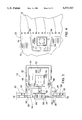
- FIG. 1 an exploded view of a television cabinet and a bracket apparatus in accordance with the present invention.
- FIG. 2 is an enlarged view of balloon section 15 of FIG. 1.
- FIG. 3 is a side view along view line 3--3 of FIG. 2 which shows a mounting flange in an assembled position.
- FIG. 4 is an enlarged view of balloon section 15 of FIG. 1 which depicts the bracket apparatus secured between a beznet and a rear cover.
- FIGS. 1-4 wherein like elements are referenced by like referenced numerals.
- FIG. 1 an exploded view of a television cabinet 11 having a front portion, or beznet 10, and a rear cover 12 is shown.
- a bracket apparatus 14 in accordance with the present invention is shown positioned between the beznet 10 and the rear cover 12. It is noted that the bracket apparatus 14 may also be used in conjunction with other electronic apparatus having a cabinet such as computer monitors, stereo systems and video cassette recorders.
- the beznet 10 includes a side wall 16 having a first vertical edge 18 and a notch 20 which extends through a portion of the first edge 18.
- the rear cover 12 includes a second vertical edge 22 which is adapted to abut against the first edge 18 and the bracket apparatus 14.
- the notch 20 is defined by a substantially C-shaped peripheral edge 24.
- the side wall 16 includes a wall flange element 26 which extends from the first edge 18 and from the peripheral edge 24 to form a substantially C-shaped notch flange element 28 having a flange top surface 30 within the notch 20.
- the bracket apparatus 14 includes a housing 32 and a mounting flange element 34.
- the mounting flange 34 is shaped to correspond to the shape of the peripheral edge 24. Further, the mounting flange 34 includes an aperture 36 and a vertical bracket edge 38 which extends through the aperture 36. In order to position the bracket apparatus 14 into an assembled position (as shown in FIG.
- the mounting flange 34 is positioned onto the flange top surface 30.
- the mounting flange 34 is then slid on the flange top surface 30 and into the notch 20 until the bracket edge 38 corresponds with the first edge 18.
- the flange top surface 30 is substantially covered by the mounting flange 34 to provide an integrated appearance which enhances aesthetic appeal of the cabinet.
- FIG. 3 a side view along view line 3--3 of FIG. 2 is shown.
- the mounting flange 34 is shown in the assembled position.
- the notch flange 28 has a predetermined flange thickness.
- the housing 32 includes top 42 and bottom 44 ribs each of which are spaced apart from the mounting flange 34 by a predetermined distance which is less than the flange thickness by an amount suitable for forming an interference, or press, fit.
- the housing 32, mounting flange 34 and the top 42 and bottom ribs 44 are each fabricated from a resilient material such as plastic.
- the resiliency of the housing 32, mounting flange 34 and the top 42 and bottom 44 ribs causes the generation of a clamping force which clamps the notch flange 28 between the top 42 and bottom 44 ribs to form the press fit.
- This removably secures the bracket apparatus 14 to the notch flange 28 and thus side wall 16 without the use of fasteners, thus reducing complexity and manufacturing costs.
- the bracket apparatus 14 is removably secured without the rear cover 12 being secured to the beznet 10. This provides access to interior sections of the television set during the manufacturing process, thus enabling the performance of various manufacturing operations as the television set is being tested.
- the housing 32 further includes top 46 and bottom 48 restraining clips.
- the top 46 and bottom 48 clips serve to releasably secure a printed circuit board 50 or other element within the housing 32.
- a switch is mounted on the printed circuit board 50.
- the switch may be any type of commercially available switch such as a two position push switch 52 having a body 54 and a shaft 56 which extends from the body 54. In this type of switch, the shaft 56 may be moved between a first, or off, position wherein the shaft 56 is fully extended out of the body 54 and a second, or on, position wherein the shaft 56 is partially inserted within the body 54.
- a button element 58 is affixed to an end of the shaft 56.
- the button element 58 extends through the aperture 36 to enable manipulation of the push switch 52 by an operator. In use, an operator may turn the push switch 52 on or off by depressing the button element 58 as desired.
- the push switch 52 is electrically connected to serve as a main power switch for turning the television set on or off. As such, this enables the testing of selected operating parameters of the television set before manufacture of the television set is completed. Further, such testing is performed in conjunction with the manufacture of the television set due to the access provided by not having the rear cover 12 assembled to the beznet 10. As a result, manufacturing time and thus costs, are reduced.
- FIG. 4 an enlarged view of balloon section 15 is shown wherein the beznet 10, bracket apparatus 14 and rear cover 12 are shown assembled.
- the rear cover 12 is secured to the beznet 10 by conventional fasteners.
- the second edge 22 abuts the first edge 18 and the bracket edge 38 to thus inhibit movement of the bracket apparatus 14 out of the notch 20, thus securing the bracket apparatus 14 within the beznet 10.
- the second edge 22 is adapted to substantially cover the wall flange 26, thus enhancing aesthetic appeal.
- the bracket apparatus 14 and thus push switch 52 are secured to the cabinet 11 without the use of fasteners.
- the notch 20 may be formed in other walls of the cabinet 11 to provide other desired placements of the bracket apparatus 14.
Landscapes
- Engineering & Computer Science (AREA)
- Theoretical Computer Science (AREA)
- Computer Hardware Design (AREA)
- Power Engineering (AREA)
- Human Computer Interaction (AREA)
- Physics & Mathematics (AREA)
- General Engineering & Computer Science (AREA)
- General Physics & Mathematics (AREA)
- Multimedia (AREA)
- Signal Processing (AREA)
- Casings For Electric Apparatus (AREA)
Abstract
Description
Claims (10)
Priority Applications (1)
| Application Number | Priority Date | Filing Date | Title |
|---|---|---|---|
| US08/438,597 US5573317A (en) | 1995-05-10 | 1995-05-10 | Bracket apparatus for a cabinet |
Applications Claiming Priority (1)
| Application Number | Priority Date | Filing Date | Title |
|---|---|---|---|
| US08/438,597 US5573317A (en) | 1995-05-10 | 1995-05-10 | Bracket apparatus for a cabinet |
Publications (1)
| Publication Number | Publication Date |
|---|---|
| US5573317A true US5573317A (en) | 1996-11-12 |
Family
ID=23741264
Family Applications (1)
| Application Number | Title | Priority Date | Filing Date |
|---|---|---|---|
| US08/438,597 Expired - Lifetime US5573317A (en) | 1995-05-10 | 1995-05-10 | Bracket apparatus for a cabinet |
Country Status (1)
| Country | Link |
|---|---|
| US (1) | US5573317A (en) |
Cited By (12)
| Publication number | Priority date | Publication date | Assignee | Title |
|---|---|---|---|---|
| US5991153A (en) * | 1997-10-31 | 1999-11-23 | Lacerta Enterprises, Inc. | Heat transfer system and method for electronic displays |
| US6215655B1 (en) | 1997-10-31 | 2001-04-10 | Lacerta Enterprises, Inc. | Drive-in ordering apparatus |
| US6328206B1 (en) * | 1997-11-28 | 2001-12-11 | Diebold, Incorporated | Adjustable display mounting mechanism for automated banking machine |
| US20030095214A1 (en) * | 2001-11-16 | 2003-05-22 | Chen Kuo-Wen | Monitor fabrication method and device |
| US20030151701A1 (en) * | 2002-02-12 | 2003-08-14 | Marty Sedighzadeh | Television monitor with ceiling and wall mounting system |
| US20030168950A1 (en) * | 2002-03-07 | 2003-09-11 | Matsushita Elec. Ind. Co. Ltd. | Tag holding member, and device including tag holding member |
| US20050204518A1 (en) * | 2002-11-19 | 2005-09-22 | Digit | Profiled section for door or bay frame |
| US20080007670A1 (en) * | 2006-07-07 | 2008-01-10 | Innolux Display Corp. | Flat panel display having fixing members |
| US20080083548A1 (en) * | 2006-10-10 | 2008-04-10 | Makoto Nakayama | Structure for housing electrical junction box in housing box |
| US20080239692A1 (en) * | 2006-08-31 | 2008-10-02 | Makoto Nakayama | Mounting structure of electrical junction box |
| US20080278039A1 (en) * | 2007-05-08 | 2008-11-13 | Funai Electric Co., Ltd. | Display device |
| EP2157787A1 (en) * | 2008-08-20 | 2010-02-24 | Funai Electric Co., Ltd. | Control key unit for television receiver |
Citations (8)
| Publication number | Priority date | Publication date | Assignee | Title |
|---|---|---|---|---|
| US2779833A (en) * | 1953-09-24 | 1957-01-29 | Essex Wire Corp | Automobile door switch |
| US3213213A (en) * | 1962-04-12 | 1965-10-19 | Allen Bradley Co | Electrical contact actuator |
| US3828291A (en) * | 1973-06-14 | 1974-08-06 | Mc Graw Edison Co | Protector for electric circuit |
| US4080522A (en) * | 1976-06-10 | 1978-03-21 | Cutler-Hammer, Inc. | Snap-in arrangement for mounting devices in a support panel aperture |
| US4340795A (en) * | 1980-07-29 | 1982-07-20 | Amf Incorporated | Panel mount adapter for switches |
| US4406936A (en) * | 1980-10-11 | 1983-09-27 | Nihon Kaiheiki Kogyo Kabushiki Kaisha | Mounting frame equipped with decorative plate for mounting switch or the like |
| US5217190A (en) * | 1990-08-10 | 1993-06-08 | The Siemon Company | Panel yoke |
| US5235493A (en) * | 1992-05-15 | 1993-08-10 | Sinotek International Co., Ltd. | Alternately horizontal or vertical computer main frame housing |
-
1995
- 1995-05-10 US US08/438,597 patent/US5573317A/en not_active Expired - Lifetime
Patent Citations (8)
| Publication number | Priority date | Publication date | Assignee | Title |
|---|---|---|---|---|
| US2779833A (en) * | 1953-09-24 | 1957-01-29 | Essex Wire Corp | Automobile door switch |
| US3213213A (en) * | 1962-04-12 | 1965-10-19 | Allen Bradley Co | Electrical contact actuator |
| US3828291A (en) * | 1973-06-14 | 1974-08-06 | Mc Graw Edison Co | Protector for electric circuit |
| US4080522A (en) * | 1976-06-10 | 1978-03-21 | Cutler-Hammer, Inc. | Snap-in arrangement for mounting devices in a support panel aperture |
| US4340795A (en) * | 1980-07-29 | 1982-07-20 | Amf Incorporated | Panel mount adapter for switches |
| US4406936A (en) * | 1980-10-11 | 1983-09-27 | Nihon Kaiheiki Kogyo Kabushiki Kaisha | Mounting frame equipped with decorative plate for mounting switch or the like |
| US5217190A (en) * | 1990-08-10 | 1993-06-08 | The Siemon Company | Panel yoke |
| US5235493A (en) * | 1992-05-15 | 1993-08-10 | Sinotek International Co., Ltd. | Alternately horizontal or vertical computer main frame housing |
Cited By (20)
| Publication number | Priority date | Publication date | Assignee | Title |
|---|---|---|---|---|
| US5991153A (en) * | 1997-10-31 | 1999-11-23 | Lacerta Enterprises, Inc. | Heat transfer system and method for electronic displays |
| US6215655B1 (en) | 1997-10-31 | 2001-04-10 | Lacerta Enterprises, Inc. | Drive-in ordering apparatus |
| US6328206B1 (en) * | 1997-11-28 | 2001-12-11 | Diebold, Incorporated | Adjustable display mounting mechanism for automated banking machine |
| US20030095214A1 (en) * | 2001-11-16 | 2003-05-22 | Chen Kuo-Wen | Monitor fabrication method and device |
| US20030151701A1 (en) * | 2002-02-12 | 2003-08-14 | Marty Sedighzadeh | Television monitor with ceiling and wall mounting system |
| US20030168950A1 (en) * | 2002-03-07 | 2003-09-11 | Matsushita Elec. Ind. Co. Ltd. | Tag holding member, and device including tag holding member |
| US6820951B2 (en) * | 2002-03-07 | 2004-11-23 | Matsushita Electric Industrial Co., Ltd. | Tag holding member, and device including tag holding member |
| US20050204518A1 (en) * | 2002-11-19 | 2005-09-22 | Digit | Profiled section for door or bay frame |
| US8042844B2 (en) * | 2002-11-19 | 2011-10-25 | Digit | Profiled section for door or bay frame |
| US20080007670A1 (en) * | 2006-07-07 | 2008-01-10 | Innolux Display Corp. | Flat panel display having fixing members |
| US20080239692A1 (en) * | 2006-08-31 | 2008-10-02 | Makoto Nakayama | Mounting structure of electrical junction box |
| US7696432B2 (en) * | 2006-08-31 | 2010-04-13 | Yazaki Corporation | Mounting structure of electrical junction box |
| US7459631B2 (en) * | 2006-10-10 | 2008-12-02 | Yazaki Corporation | Structure for housing electrical junction box in housing box |
| US20080083548A1 (en) * | 2006-10-10 | 2008-04-10 | Makoto Nakayama | Structure for housing electrical junction box in housing box |
| US20080278039A1 (en) * | 2007-05-08 | 2008-11-13 | Funai Electric Co., Ltd. | Display device |
| EP1990815A3 (en) * | 2007-05-08 | 2010-04-07 | Funai Electric Co., Ltd. | Display device |
| US8144268B2 (en) | 2007-05-08 | 2012-03-27 | Funai Electric Co., Ltd. | Display device |
| EP2157787A1 (en) * | 2008-08-20 | 2010-02-24 | Funai Electric Co., Ltd. | Control key unit for television receiver |
| US20100044201A1 (en) * | 2008-08-20 | 2010-02-25 | Funai Electric Co., Ltd. | Control key unit for television receiver |
| US8436950B2 (en) | 2008-08-20 | 2013-05-07 | Funai Electric Co., Ltd. | Control key unit for television receiver |
Similar Documents
| Publication | Publication Date | Title |
|---|---|---|
| US5573317A (en) | Bracket apparatus for a cabinet | |
| US7253370B2 (en) | Computer button apparatus | |
| US5737039A (en) | Control panel for a television | |
| JP3674056B2 (en) | Board fixing brackets for electrical equipment | |
| US20040017667A1 (en) | Electronic control unit snap-fitted to supporting bracket | |
| JPS5935012Y2 (en) | Parts mounting device | |
| JPH0227591Y2 (en) | ||
| JPH0224178Y2 (en) | ||
| JPH0119422Y2 (en) | ||
| KR970004504Y1 (en) | Combinating device for front cabinet of electronic device | |
| JPS5935931Y2 (en) | Push button mounting device in equipment | |
| JPS6336894Y2 (en) | ||
| JP2002026545A (en) | Guide rail structure | |
| JPS5830347Y2 (en) | Tuning circuit structure housing structure in television receiver | |
| JPH03177097A (en) | Cabinet device | |
| JPS5855792Y2 (en) | cabinet | |
| JPS5812340Y2 (en) | Mounting mechanism of pushbutton switch | |
| JPH081536Y2 (en) | Slide knob mounting mechanism | |
| JPH0418146Y2 (en) | ||
| JPH0731567Y2 (en) | Operation panel mounting structure | |
| JP2594140Y2 (en) | Speaker fixing structure | |
| JP2647078B2 (en) | Operation box for washing machine, etc. | |
| JP2542916Y2 (en) | Support structure for printed circuit board parts protection cover | |
| JPS5816300Y2 (en) | Senkiyokuyouhotenshiyome-ta-no-toritsuke-souchi | |
| KR900003536Y1 (en) | Controler door having knob device |
Legal Events
| Date | Code | Title | Description |
|---|---|---|---|
| AS | Assignment |
Owner name: SONY ELECTRONICS, INC., NEW JERSEY Free format text: ASSIGNMENT OF ASSIGNORS INTEREST;ASSIGNORS:CAVANAUGH, BARRY A.;OZAKI, ARTHUR H.;REEL/FRAME:007552/0494 Effective date: 19950505 |
|
| AS | Assignment |
Owner name: SONY ELECTRONICS INC., NEW JERSEY Free format text: ASSIGNMENT OF ASSIGNORS INTEREST;ASSIGNOR:SONY ELECTRONICS INC.;REEL/FRAME:008081/0104 Effective date: 19960730 Owner name: SONY CORPORATION, JAPAN Free format text: ASSIGNMENT OF ASSIGNORS INTEREST;ASSIGNOR:SONY ELECTRONICS INC.;REEL/FRAME:008081/0104 Effective date: 19960730 |
|
| STCF | Information on status: patent grant |
Free format text: PATENTED CASE |
|
| FEPP | Fee payment procedure |
Free format text: PAYOR NUMBER ASSIGNED (ORIGINAL EVENT CODE: ASPN); ENTITY STATUS OF PATENT OWNER: LARGE ENTITY |
|
| FPAY | Fee payment |
Year of fee payment: 4 |
|
| FPAY | Fee payment |
Year of fee payment: 8 |
|
| FPAY | Fee payment |
Year of fee payment: 12 |
|
| REMI | Maintenance fee reminder mailed | ||
| AS | Assignment |
Owner name: SONY CORPORATION, JAPAN Free format text: ASSIGNMENT OF ASSIGNORS INTEREST;ASSIGNOR:SONY ELECTRONICS INC.;REEL/FRAME:036330/0420 Effective date: 20150731 |