US5577267A - Assembly for visually indicating signals generated by an electrical circuit and light-diffusing interface apparatus therefor - Google Patents
Assembly for visually indicating signals generated by an electrical circuit and light-diffusing interface apparatus therefor Download PDFInfo
- Publication number
- US5577267A US5577267A US07/966,659 US96665992A US5577267A US 5577267 A US5577267 A US 5577267A US 96665992 A US96665992 A US 96665992A US 5577267 A US5577267 A US 5577267A
- Authority
- US
- United States
- Prior art keywords
- light
- sheet
- generative
- spaced
- translucent material
- Prior art date
- Legal status (The legal status is an assumption and is not a legal conclusion. Google has not performed a legal analysis and makes no representation as to the accuracy of the status listed.)
- Expired - Lifetime
Links
Images


Classifications
-
- H—ELECTRICITY
- H04—ELECTRIC COMMUNICATION TECHNIQUE
- H04M—TELEPHONIC COMMUNICATION
- H04M1/00—Substation equipment, e.g. for use by subscribers
- H04M1/02—Constructional features of telephone sets
- H04M1/22—Illumination; Arrangements for improving the visibility of characters on dials
-
- H—ELECTRICITY
- H01—ELECTRIC ELEMENTS
- H01H—ELECTRIC SWITCHES; RELAYS; SELECTORS; EMERGENCY PROTECTIVE DEVICES
- H01H13/00—Switches having rectilinearly-movable operating part or parts adapted for pushing or pulling in one direction only, e.g. push-button switch
- H01H13/70—Switches having rectilinearly-movable operating part or parts adapted for pushing or pulling in one direction only, e.g. push-button switch having a plurality of operating members associated with different sets of contacts, e.g. keyboard
- H01H13/702—Switches having rectilinearly-movable operating part or parts adapted for pushing or pulling in one direction only, e.g. push-button switch having a plurality of operating members associated with different sets of contacts, e.g. keyboard with contacts carried by or formed from layers in a multilayer structure, e.g. membrane switches
-
- H—ELECTRICITY
- H01—ELECTRIC ELEMENTS
- H01H—ELECTRIC SWITCHES; RELAYS; SELECTORS; EMERGENCY PROTECTIVE DEVICES
- H01H2219/00—Legends
- H01H2219/002—Legends replaceable; adaptable
- H01H2219/014—LED
-
- H—ELECTRICITY
- H01—ELECTRIC ELEMENTS
- H01H—ELECTRIC SWITCHES; RELAYS; SELECTORS; EMERGENCY PROTECTIVE DEVICES
- H01H2219/00—Legends
- H01H2219/054—Optical elements
- H01H2219/056—Diffuser; Uneven surface
-
- H—ELECTRICITY
- H01—ELECTRIC ELEMENTS
- H01H—ELECTRIC SWITCHES; RELAYS; SELECTORS; EMERGENCY PROTECTIVE DEVICES
- H01H2219/00—Legends
- H01H2219/054—Optical elements
- H01H2219/064—Optical isolation of switch sites
Definitions
- the present invention relates generally to light diffusers and, more particularly, to a light-diffusing interface apparatus for diffusing light generated by a light-generative device.
- a communication system is operative to transmit information between two or more locations, and includes, at a minimum, a transmitter and a receiver interconnected by a communication channel.
- the communication channel comprises a radio frequency channel wherein a radio frequency channel is defined by a range of frequencies of the communication spectrum.
- Information is transmitted by the transmitter to the receiver by transmitting the information upon the radio frequency channel to the receiver.
- the transmitter which forms a portion of the radio communication system includes circuitry for converting the information into a form suitable for transmission thereof upon a radio frequency channel.
- circuitry includes modulation circuitry which performs a process referred to as modulation.
- modulation the information which is to be transmitted is impressed upon a radio frequency electromagnetic wave, commonly referred to as a carrier signal.
- the resultant signal formed of a combination of the carrier signal and the information, is commonly referred to as a modulated signal.
- Such resultant signal is also referred to as a communication signal as the modulated signal includes the information which is to be communicated by the transmitter to the receiver.
- modulation schemes for impressing the information upon the carrier signal, thereby to form the communication signal.
- modulation schemes For instance, amplitude modulation, frequency modulation, phase modulation, and combinations of such modulation schemes are all modulation schemes by which the information may be impressed upon the carrier wave to form the communication signal.
- Radio communication systems are advantageous in that no physical interconnection is required between the transmitter and the receiver; once the information is modulated to form a modulated signal, a modulated signal may be transmitted over large distances.
- Numerous modulated signals may be simultaneously transmitted upon different radio frequency channels defined upon the electromagnetic frequency spectrum. Transmission of modulated signals on different ones of the radio frequency channels defined upon certain frequency bands of the electromagnetic frequency spectrum is regulated by regulatory bodies.
- a two-way, radio communication system is a radio communication system, similar to the radio communication system above-described, but which further permits both transmission and reception of information at first and second, spaced-apart locations.
- Each location of a two-way radio communication system contains both a transmitter and a receiver.
- the transmitter and the receiver positioned at a single location typically comprise a unit referred to as a radio transceiver, or, more simply, a transceiver.
- a transceiver capable of alternate operation either to transmit or to receive a communication signal is referred to as being capable of simplex operation.
- a transceiver capable of simultaneous operation both to transmit and to receive a communication signal is referred to as being capable of duplex operation.
- a cellular communication system is one type of two-way radio communication system in which communication is permitted with a radio transceiver positioned at any location within a geographic area encompassed by the cellular communication system.
- a cellular communication system is created by positioning a plurality of fixed-site radio transceivers referred to as base stations, at spaced-apart locations throughout the geographic area.
- the base stations are connected to a conventional, wireline, telephonic network.
- Each base station has associated therewith a portion of the geographic area located proximate to each of such base stations. Such portions are referred to as cells.
- the plurality of cells each defined by corresponding ones of the base stations of the plurality of base stations together define the coverage area of the cellular communication system.
- a radio transceiver referred to in the cellular communication system as a radiotelephone, positioned within any location within the coverage area of the cellular communication system is able to communicate with a user of the conventional, wireline, telephonic network by way of a base station. Modulated signals are transmitted between the radiotelephone and the base station to effectuate communication therebetween.
- the radiotelephone includes a handset assembly operative in a manner analogous to the operation of a handset assembly of conventional telephonic apparatus.
- the handset assembly In some radiotelephone constructions, only portions of the circuitry of the radiotelephone is disposed within the handset assembly, In such constructions, the handset assembly is coupled to transceiver circuitry housed within other structure. In other radiotelephone constructions, the entire circuitry of the radiotelephone is housed within the handset assembly thereof.
- the handset assembly includes structure to facilitate operation of the radiotelephone.
- structure typically requires the interaction of a user, such structure is typically referred to as a user interface.
- the handset assembly of either type of radiotelephone includes a user interface which permits the user to effectuate telephonic communication by way of the radiotelephone with a remote site.
- Such user interface typically comprises a telephonic keypad to permit the user to enter a desired call sequence (i.e., a telephone number) thereby to effectuate telephonic communication with a location associated with such call sequence.
- information is provided by the radiotelephone to indicate to the user of such radiotelephone certain parameters of operation of such radiotelephone.
- information is provided in the form of a visual indication by light-generative devices, usually light emitting diodes.
- Light emitting diodes are advantageously utilized to provide the indications to the user of the parameters of operation of the radiotelephone as the light emitting diodes are operable at low power levels. Use of such light emitting diodes is particularly advantageous when the radiotelephone is powered by a portable power source.
- Diodes generate a nondiffuse light pattern. Because of this characteristic, many designs of radiotelephone constructions position the diodes near the surface of the housing of the handset assembly, thereby to ensure that the light generated by such diodes is noticeable to the user of the radiotelephone.
- Radiotelephones are oftentimes operated in darkened conditions.
- the keypad supported by the handset assembly oftentimes also includes light-generative devices, once again typically formed of light emitting diodes, for illuminating the keypad display.
- the keypad display is comprised of a thermoelastic, and also translucent, material.
- the thermoelastic and translucent material may, for example, be comprised of a silicone rubber-type material.
- the light emitting diodes forming the light-generative devices which illuminate the keypad display are positioned beneath individual actuation switches of the keypad display.
- the translucent keypad acts to diffuse the point-intensive light pattern of the light generated by the light emitting diodes. When the diodes are lighted, the diffusion of the light caused by the keypad display causes the entire keypad display to be illuminated.
- What is needed is a light-diffusing interface apparatus for diffusing light generated by light-generative devices for an electronic device which does not increase the product part count of the electronic device and which minimizes light bleed between adjacently-positioned light-generative devices.
- the present invention accordingly, advantageously provides a light-diffusing interface apparatus for diffusing light generated by a light generative device.
- the present invention further advantageously provides an assembly for visually indicating signals generated by an electrical circuit.
- the present invention yet further advantageously provides an interface apparatus for a radio transceiver.
- an assembly for visually indicating signals generated by an electrical circuit comprises at least two light-generative devices coupled to the electrical circuit wherein a first light-generative device of the at least two light-generative devices is operative to turn-on when a first of the signals is generated by the electrical circuit.
- a second light-generative device of the light-generative devices is spaced apart from the first of the light-generative devices and is operative to turn-on when a second of the signals is generated by the electrical circuit.
- a sheet of translucent material is positioned above both the first and second light-generative devices, respectively, of the at least two light-generative devices.
- At least two spaced-apart light diffusers formed of the translucent material comprising the sheet of translucent material is positioned to extend beyond a top surface of the sheet of the translucent material.
- a first light diffuser and a second light diffuser of the at least two light diffusers are spaced-apart by distances corresponding to distances at which the first and second light-generative devices, respectively, are spaced-apart, thereby to permit alignment of the first light diffuser with the first light-generative device and alignment of the second light diffuser with the second light-generative device.
- Light emitted by the first and second light-generative devices, respectively are diffused by corresponding ones of the first and second light diffusers.
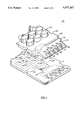
- FIG. 1 is an exploded, cutaway view of the assembly of a preferred embodiment of the present invention for visually indicating signals generated by an electrical circuit;
- FIG. 2 is an exploded, cutaway view of the assembly of FIG. 1 positioned to form a portion of a telephonic handset assembly;
- FIG. 3 is a perspective view of a radiotelephone of a preferred embodiment of the present invention which incorporates the assembly of the preceding figures as a portion thereof;
- FIG. 4 is a sectional view taken along lines IV--IV of FIG. 3.
- Assembly 100 is operative to indicate visually signals generated by an electrical circuit.
- the electrical circuit is represented by block 106, shown in hatch, which is disposed primarily upon a bottom surface of circuit board 112.
- Electrical circuit 106 generates signals on lines 118 (here five lines 118 are shown) which lead to light-generative devices 124.
- light-generative devices 124 are comprised of light emitting diodes.
- Circuit board 112 of FIG. 1 is further shown to include an array of input terminals 134 at which input signals are applied, thereafter to be supplied to electrical circuit 106 by way of lines 140. As illustrated, input terminals 134 are arranged in rows and columns to form an array of terminals. Additional light-generative devices 146 are further disposed upon circuit board 112. Light-generative devices 146 are also preferably comprised of light emitting diodes and are also connected to electrical circuit 106 by electrically-conductive lines (not shown in the figure).
- Keypad interface 150 is positioned above a top face surface of circuit board 112 and is of dimensions permitting tandem positioning of a face surface of keypad interface 150 upon the top face surface of circuit board 112.
- Keypad interface 150 includes a plurality of keypad push buttons 156 arranged in rows and columns to form an array of keypad pushbuttons. Individual ones of the keypad pushbuttons 156 are spaced-apart by distances corresponding to distances at which input terminals 134 are spaced-apart upon the top face surface of circuit board 112.
- Keypad interface 150 is comprised of a flexible, thermoelastic material and is constructed to permit limited vertical translation of individual ones of the keypad pushbuttons 156.
- keypad interface 150 is comprised of a silicone rubber-type material.
- the thermoelastic material comprising keypad interface 150 is preferably translucent and is both light-diffusive and light-transmissive.
- Keypad pushbuttons 156 also comprised of the silicone rubber-type material are similarly both light-diffusive and light-transmissive.
- An electrically-conductive material is coated upon bottom portions (not shown in FIG. 1) of the keypad pushbuttons 156.
- a bottom face surface of keypad interface 150 is aligned with circuit board 112 and is positioned upon the front face surface of circuit board 112, individual ones of the keypad pushbuttons 156 of the array of pushbuttons 156 are aligned with corresponding ones of the input terminals 134 of the array of input terminals 134.
- Keypad pushbuttons 156 are actuated by application of a downward translation force upon face surfaces of individual ones of keypad pushbuttons 156. Translation of keypad pushbuttons 156 responsive to application of such actuation force thereto causes the bottom portions of such keypad pushbuttons 156, coated with the electrically-conductive material, to abut against input terminals 134. Such abutment of the electrically-conductive coating upon adjoining input terminals 134 closes contacts comprising each of the terminals 134 and thereby form the input signals applied to electrical circuit 106.
- Keypad pushbuttons 156 are arranged in a configuration corresponding to the configuration of a conventional, telephonic keypad and are operative to permit manual entry of a desired call sequence corresponding to a telephone number to be entered by a user.
- Sheet 170 is formed integral with keypad interface 150 to extend beyond a top edge surface thereof.
- Sheet 170 is comprised of the same thermoelastic material of which keypad interface 150 is comprised.
- sheet 170, integrally formed with keypad interface 150 is comprised of the silicone rubber-type material.
- the thermoelastic material comprising sheet 170 is also translucent to be both light transmissive and light-diffusive thereby.
- Sheet 170 is of like a comb-like configuration forming a spine-portion 176 with toothed-portions 182 extending therefrom. In the embodiment of FIG. 1, five toothed-portions extend beyond spine-portion 176. Adjacent ones of the tooth-portions 182 are spaced-apart from each other to define thereby gaps 188 therebetween.
- Light diffusers 194 are formed to extend beyond a top face surface of each tooth-portion 182 of sheet 170 and are comprised of the same material as that of sheet 170 and keypad interface 150. As illustrated, light diffusers 194 are conically-shaped and have truncated top ends. Each light diffuser 194 forms a truncated conical body thereby. While diffusers 194 are integrally formed with sheet 170, the diffusers are formed to be of thicknesses less than the thickness of sheet 170 (and also keypad interface 150) thereby to be more greatly light-transmissive (and less light-diffusive) than sheet 170 (and keypad interface 150).
- Individual ones of the toothed-portions 182 are spaced apart by distances such that when keypad interface 150 is positioned in tandem with the top face surface of circuit board 112 to align keypad pushbuttons 156 with corresponding input terminals 134, light diffusers 194 formed upon the individual ones of the toothed-portions 182 align with individual ones of the light-generative devices 124. Once positioned as such, light emitted by individual ones of the light-generative devices 124 pass through a corresponding light diffuser 194 positioned thereabove.
- light diffusers 194 are operative to diffuse the light directed thereat, light generated by individual ones of the light generative devices 124 is diffused by a light diffuser 194 positioned thereabove, and the entire surface area of the particular one of the light diffusers 194 positioned over top the particular light-generative device 124 is illuminated.
- gaps 188 are formed between adjacent ones of toothed-portions 182, light generated by any particular ones of the light-generative devices 124 is transmitted through only the toothed-portion 182 and the associated light diffuser 194 positioned thereabove; such light is not transmitted to an adjacent one of the toothed-portions 182.
- Transversely-extending channel 198 formed proximate to the intersection between keypad interface 150 and sheet 170 extends across a substantial portion of the distance between opposing side surfaces of keypad interface 150 and sheet 170. While not shown in the view of FIG. 1, a similar such channel (spaced somewhat apart from that of channel 198) is formed to extend transversely along a bottom side of the structure proximate to the intersection of keypad interface 150 and sheet 170.
- Such channels are operative to minimize undesired transmission of light (i.e., light bleed) through the thermoelastic material comprising interface 150 and sheet 170 of light generated by either any of the light-generative devices 124 or light-generative devices 146.
- FIG. 2 a portion of handset assembly 200 is shown in exploded form.
- Assembly 100 of FIG. 1 forms a portion of handset assembly 220.
- commonly-numbered circuit board 112, keypad interface 150 and sheet 170 extending from a top edge surface thereof form portions of handset assembly 200.
- FIG. 2 illustrates the face surface of circuit board 112 hidden from view in FIG. 1 upon which substantial portions of electrical circuit 106 are disposed as well as lines 118 which extend to light-generative devices 124.
- Keypad interface 150 is again shown to include keypad pushbuttons 156 which are arranged to form an array of pushbuttons 156. And, the plurality of toothed-portions 182 and light diffusers 194 are also again shown in the figure.
- the view of FIG. 2 further illustrates transversely-extending channel 199 which forms the channel, noted briefly hereinabove, which is substantially similar to that of channel 198 shown FIG. 1.
- Handset assembly 200 is further shown to include handset housing portions 216 and 222.
- Handset housing portions 216 and 222 are of dimensions permitting supportive housing therewithin of, inter alia, circuit board 112, keypad interface 150, and sheet 170.
- An inner wall 228 of handset housing portion 222 is further illustrated in the view of the figure.
- a plurality of spaced-apart, longitudinally-extending rib members 234 are formed upon inner wall 228.
- Rib members 234 are spaced-apart by distances corresponding to the widths of toothed-portions 182 of sheet 170 (and, hence, also to the distances separating gaps 188 formed at opposing sides of toothed-portions 182). Such spacing of rib members 234 thereby permits interfitting engagement of such rib members 234 with toothed-portions 182 when such toothed-portions 182 are suitably aligned therewith.
- Rib members 234 are operative thereby to support toothed-portions 182 in position.
- rib members 234 are comprised of an opaque material, the rib members are operative to prevent undesired transmission of light (i.e., light bleed) generated by light-generative devices 124 once circuit board 112 and keypad interface 150 are tandemly positioned and toothed-portions 182 and rib members 234 are positioned in the interfitting engagement therebetween.
- light bleed undesired transmission of light
- Apertures 240 are formed to extend through handset housing portion 222 at locations between adjacent ones of the rib members 234. Apertures 240 extend the entire distances between inner wall 228 of housing portion 222 and a corresponding outer wall of the housing portion. Apertures 240 are of diameters permitting insertion therein of portions of light diffusers 194. Apertures 240 are thereby operative to support light diffusers 194 in position once toothed-portions 182 are positioned in the interfitting engagement with rib members 234.
- the top edge surfaces of the truncated, conical bodies forming light diffusers 194 may be positioned flush with an outer wall of handset housing portion 222 once the light diffusers 194 are positioned to extend into apertures 240. Because light diffusers 194 are operative to diffuse the light generated by light-generative devices 124, a uniformly-lighted circular area corresponding to the top edge surface of a light diffuser 194 appears at the outer wall of handset housing portion 222 when a light-generative device 124 is lighted. Because of gaps 182 positioned between adjacent toothed-portions 182, opaque rib members 234, and channels 198 and 199, light bleed of light transmitted through the translucent material comprising sheet 170 and light diffusers 194 is insignificant.
- Radiotelephone 300 includes commonly-numbered, housing assembly 200 shown in the exploded view of FIG. 2 as a portion thereof. Housing assembly 200 is again shown to be comprised of handset housing portions 216 and 222. Circuit board 112, keypad interface 150, and sheet 170 are supported within assembly 200.
- Radiotelephone 300 further includes radio transceiver circuit 312 which is coupled to the circuitry, including circuit board 112, housed within handset assembly 200. It should be noted that, while radio transceiver circuitry 312 is illustrated in the figure as being located separate from handset assembly 200, radio transceiver circuitry 312 may also alternately be housed entirely within handset assembly 200. In such an embodiment, radiotelephone 300 forms a portable radiotelephone.
- Keypad pushbuttons 156 extend through openings formed to extend through handset housing portion 222 to be accessible by a user of radiotelephone 300. A user may utilize such keypad pushbuttons 156 to enter a call sequence corresponding to a telephone number by application of actuation forces upon individual ones of the keypad pushbuttons 156.
- Apertures 240 and top end portions of light diffusers 194 are further illustrated in the perspective view of radiotelephone 300 of FIG. 3.
- Light generated by individual ones of the light-generative devices 124 shown in the preceding figures is diffused by a light diffuser 194 positioned thereupon, as described previously, thereby to provide a uniformly-lighted indication at the circular, top-end portion of the associated light diffuser 194 visible from the exterior of handset assembly 200. Because light bleed is insignificant, a mistaken indication of lighting of one or another of the light-generative devices is obviated.
- FIG. 4 a sectional view of a portion of handset assembly 200 taken along lines IV--IV of FIG. 3 is shown.
- Light generated by light-generative device 124 is diffused by light diffuser 194.
- Top surface 350 of light diffuser 194 is positioned beneath lens 360 and is spaced apart therefrom by a slight distance for aesthetic reasons. (Positioning of top surface 350 is abutting engagement with a surface of lens 360 can result in an aesthetically displeasing appearance referred to as a "water effect.")
- top surface 350 is somewhat greater than sidewalls of diffuser 194 thereby to increase the amount of diffusion of light directed thereat by light-generative device 124 and may be of any desired thickness to cause a desired amount of light diffusion of light generated thereat.
Abstract
Description
Claims (20)
Priority Applications (3)
| Application Number | Priority Date | Filing Date | Title |
|---|---|---|---|
| US07/966,659 US5577267A (en) | 1992-10-26 | 1992-10-26 | Assembly for visually indicating signals generated by an electrical circuit and light-diffusing interface apparatus therefor |
| MX9306609A MX9306609A (en) | 1992-10-26 | 1993-10-25 | UNIT FOR VISUALLY INDICATING SIGNALS, GENERATED BY AN ELECTRICAL CIRCUIT, AND A LIGHT DIFFUSING INTERFACE APPARATUS FOR THE SAME. |
| ITRM930704A IT1262410B (en) | 1992-10-26 | 1993-10-25 | COMPLEX FOR INDICATING VISUALLY THE SIGNALS GENERATED BY AN ELECTRIC CIRCUIT AND RELATED LIGHT DIFFUSER INTERFACE DEVICE. |
Applications Claiming Priority (1)
| Application Number | Priority Date | Filing Date | Title |
|---|---|---|---|
| US07/966,659 US5577267A (en) | 1992-10-26 | 1992-10-26 | Assembly for visually indicating signals generated by an electrical circuit and light-diffusing interface apparatus therefor |
Publications (1)
| Publication Number | Publication Date |
|---|---|
| US5577267A true US5577267A (en) | 1996-11-19 |
Family
ID=25511715
Family Applications (1)
| Application Number | Title | Priority Date | Filing Date |
|---|---|---|---|
| US07/966,659 Expired - Lifetime US5577267A (en) | 1992-10-26 | 1992-10-26 | Assembly for visually indicating signals generated by an electrical circuit and light-diffusing interface apparatus therefor |
Country Status (3)
| Country | Link |
|---|---|
| US (1) | US5577267A (en) |
| IT (1) | IT1262410B (en) |
| MX (1) | MX9306609A (en) |
Cited By (16)
| Publication number | Priority date | Publication date | Assignee | Title |
|---|---|---|---|---|
| US5722055A (en) * | 1995-02-16 | 1998-02-24 | Fujitsu Limited | Portable radiotelephone terminal adaptable to multiple models |
| EP0899762A1 (en) * | 1997-08-28 | 1999-03-03 | Alps Electric Co., Ltd. | Illuminated pushbutton switch |
| EP1094482A2 (en) * | 1999-10-19 | 2001-04-25 | Nokia Mobile Phones Ltd. | Light guide for illuminating the display or keyboard of a portable communication device |
| US6347218B1 (en) * | 1996-02-28 | 2002-02-12 | Nokia Mobile Phones Limited | Electronic device with housing supplement |
| EP1263009A2 (en) * | 2001-06-01 | 2002-12-04 | Siemens Aktiengesellschaft | Keyboard with backlighting |
| US20020183098A1 (en) * | 2001-04-20 | 2002-12-05 | Yung-Tang Lee | Cellular phone with caller ID light arrangement |
| US20030138097A1 (en) * | 1996-02-28 | 2003-07-24 | Thomas Fuhrmann | Radiotelephone |
| US6728555B1 (en) * | 1999-09-29 | 2004-04-27 | Nokia Mobile Phones, Ltd. | Display frame with integrated ESD shield, and a user interface construction |
| US20040102232A1 (en) * | 2000-12-29 | 2004-05-27 | Frank Nuovo | Mobile telephone |
| US6751484B1 (en) * | 1999-07-08 | 2004-06-15 | Telefonaktiebolaget Lm Ericsson | Portable communication apparatus having visual indicator means and a method of providing visual status indication thereof |
| US20040132504A1 (en) * | 2000-12-29 | 2004-07-08 | Michael Hague | Portable communication device |
| US20050101356A1 (en) * | 2000-12-29 | 2005-05-12 | Mark Hutchison | Casing |
| US20060260921A1 (en) * | 2005-05-19 | 2006-11-23 | Samsung Electronics Co., Ltd | Keypad assembly having reflection pattern |
| US20070051607A1 (en) * | 2005-08-23 | 2007-03-08 | Lear Corporation | Push-button switch assembly for a vehicle |
| US20070152042A1 (en) * | 2005-10-21 | 2007-07-05 | Jon Mittler | Protective cover for terminal keypad security switches |
| US20110216524A1 (en) * | 1998-08-26 | 2011-09-08 | Katrinecz Jr Andrew J | Low power low cost illuminated keyboards and keypads |
Citations (7)
| Publication number | Priority date | Publication date | Assignee | Title |
|---|---|---|---|---|
| US3670260A (en) * | 1970-05-15 | 1972-06-13 | American Optical Corp | Controlled optical beam forming device |
| US4271408A (en) * | 1978-10-17 | 1981-06-02 | Stanley Electric Co., Ltd. | Colored-light emitting display |
| US4371575A (en) * | 1979-11-05 | 1983-02-01 | Rohm Gmbh | Rigid, one-piece, biaxially stretched shaped body of synthetic resin and method for making the same |
| US4503563A (en) * | 1983-07-14 | 1985-03-05 | Jandy Industries | Electrical device in a buoyant, watertight housing |
| DE3541774A1 (en) * | 1985-11-26 | 1987-05-27 | Siemens Ag | Optical display device for electrical equipment |
| US4876709A (en) * | 1988-09-08 | 1989-10-24 | Dynascan Corporation | Antenna for cordless telephone system |
| US5210532A (en) * | 1991-09-03 | 1993-05-11 | Gerry Baby Products Company | Baby monitor receiver having indicator display and dual position clip |
-
1992
- 1992-10-26 US US07/966,659 patent/US5577267A/en not_active Expired - Lifetime
-
1993
- 1993-10-25 IT ITRM930704A patent/IT1262410B/en active IP Right Grant
- 1993-10-25 MX MX9306609A patent/MX9306609A/en not_active IP Right Cessation
Patent Citations (7)
| Publication number | Priority date | Publication date | Assignee | Title |
|---|---|---|---|---|
| US3670260A (en) * | 1970-05-15 | 1972-06-13 | American Optical Corp | Controlled optical beam forming device |
| US4271408A (en) * | 1978-10-17 | 1981-06-02 | Stanley Electric Co., Ltd. | Colored-light emitting display |
| US4371575A (en) * | 1979-11-05 | 1983-02-01 | Rohm Gmbh | Rigid, one-piece, biaxially stretched shaped body of synthetic resin and method for making the same |
| US4503563A (en) * | 1983-07-14 | 1985-03-05 | Jandy Industries | Electrical device in a buoyant, watertight housing |
| DE3541774A1 (en) * | 1985-11-26 | 1987-05-27 | Siemens Ag | Optical display device for electrical equipment |
| US4876709A (en) * | 1988-09-08 | 1989-10-24 | Dynascan Corporation | Antenna for cordless telephone system |
| US5210532A (en) * | 1991-09-03 | 1993-05-11 | Gerry Baby Products Company | Baby monitor receiver having indicator display and dual position clip |
Cited By (30)
| Publication number | Priority date | Publication date | Assignee | Title |
|---|---|---|---|---|
| US5722055A (en) * | 1995-02-16 | 1998-02-24 | Fujitsu Limited | Portable radiotelephone terminal adaptable to multiple models |
| US7092520B2 (en) | 1996-02-28 | 2006-08-15 | Nokia Corporation | Radiotelephone |
| US7885403B2 (en) | 1996-02-28 | 2011-02-08 | Nokia Corporation | Radiotelephone |
| US6347218B1 (en) * | 1996-02-28 | 2002-02-12 | Nokia Mobile Phones Limited | Electronic device with housing supplement |
| US20020057792A1 (en) * | 1996-02-28 | 2002-05-16 | Thomas Fuhrmann | Radiotelephone |
| US6487397B2 (en) | 1996-02-28 | 2002-11-26 | Nokia Mobile Phones Ltd. | Electronic device with housing supplement |
| US20060239445A1 (en) * | 1996-02-28 | 2006-10-26 | Thomas Fuhrmann | Radiotelephone |
| US20030138097A1 (en) * | 1996-02-28 | 2003-07-24 | Thomas Fuhrmann | Radiotelephone |
| US7239700B2 (en) | 1996-02-28 | 2007-07-03 | Nokia Corporation | Radiotelephone |
| US6978123B2 (en) | 1996-02-28 | 2005-12-20 | Nokia Mobile Phones Ltd. | Electronic device with housing supplement |
| EP0899762A1 (en) * | 1997-08-28 | 1999-03-03 | Alps Electric Co., Ltd. | Illuminated pushbutton switch |
| US20110216524A1 (en) * | 1998-08-26 | 2011-09-08 | Katrinecz Jr Andrew J | Low power low cost illuminated keyboards and keypads |
| US6751484B1 (en) * | 1999-07-08 | 2004-06-15 | Telefonaktiebolaget Lm Ericsson | Portable communication apparatus having visual indicator means and a method of providing visual status indication thereof |
| US6728555B1 (en) * | 1999-09-29 | 2004-04-27 | Nokia Mobile Phones, Ltd. | Display frame with integrated ESD shield, and a user interface construction |
| EP1094482A3 (en) * | 1999-10-19 | 2003-08-20 | Nokia Corporation | Light guide for illuminating the display or keyboard of a portable communication device |
| EP1094482A2 (en) * | 1999-10-19 | 2001-04-25 | Nokia Mobile Phones Ltd. | Light guide for illuminating the display or keyboard of a portable communication device |
| US20040132504A1 (en) * | 2000-12-29 | 2004-07-08 | Michael Hague | Portable communication device |
| US20050101356A1 (en) * | 2000-12-29 | 2005-05-12 | Mark Hutchison | Casing |
| US6965789B2 (en) * | 2000-12-29 | 2005-11-15 | Vertu Limited | Portable communication device |
| US20040102232A1 (en) * | 2000-12-29 | 2004-05-27 | Frank Nuovo | Mobile telephone |
| US7027844B2 (en) * | 2000-12-29 | 2006-04-11 | Vertu Limited | Mobile telephone |
| US7522943B2 (en) * | 2000-12-29 | 2009-04-21 | Vertu Limited | Casing |
| US20020183098A1 (en) * | 2001-04-20 | 2002-12-05 | Yung-Tang Lee | Cellular phone with caller ID light arrangement |
| EP1263009A3 (en) * | 2001-06-01 | 2005-01-05 | Siemens Aktiengesellschaft | Keyboard with backlighting |
| EP1263009A2 (en) * | 2001-06-01 | 2002-12-04 | Siemens Aktiengesellschaft | Keyboard with backlighting |
| US7635819B2 (en) * | 2005-05-19 | 2009-12-22 | Samsung Electronics Co., Ltd. | Keypad assembly having reflection pattern |
| US20060260921A1 (en) * | 2005-05-19 | 2006-11-23 | Samsung Electronics Co., Ltd | Keypad assembly having reflection pattern |
| US20070051607A1 (en) * | 2005-08-23 | 2007-03-08 | Lear Corporation | Push-button switch assembly for a vehicle |
| US20070152042A1 (en) * | 2005-10-21 | 2007-07-05 | Jon Mittler | Protective cover for terminal keypad security switches |
| US7832628B2 (en) * | 2005-10-21 | 2010-11-16 | Verifone, Inc. | Protective cover for terminal keypad security switches |
Also Published As
| Publication number | Publication date |
|---|---|
| MX9306609A (en) | 1994-05-31 |
| ITRM930704A1 (en) | 1995-04-25 |
| ITRM930704A0 (en) | 1993-10-25 |
| IT1262410B (en) | 1996-06-19 |
Similar Documents
| Publication | Publication Date | Title |
|---|---|---|
| US5577267A (en) | Assembly for visually indicating signals generated by an electrical circuit and light-diffusing interface apparatus therefor | |
| US5130897A (en) | Light guide for a telephone dial | |
| EP1316979B1 (en) | Illumination key | |
| US5397867A (en) | Light distribution for illuminated keyboard switches and displays | |
| US5235636A (en) | Portable telephone set housing having an illuminated switch panel | |
| KR100849320B1 (en) | Keypad for potable terminal | |
| US8362928B2 (en) | Keypad assembly | |
| DE60021154T2 (en) | Optical fiber for illuminating the display or keyboard of a portable communication device | |
| CN100469083C (en) | Electronic device | |
| JPWO2009028077A1 (en) | LIGHTING STRUCTURE FOR KEY OPERATION UNIT, ELECTRONIC DEVICE, PORTABLE DEVICE, AND LIGHTING METHOD FOR KEY OPERATION UNIT | |
| JPH04354232A (en) | Telephone set | |
| GB2366761A (en) | Light diffusion unit for mobile telephone wherein a light guide is disposed between a substrate and a light diffuser | |
| GB2285518A (en) | Sheet-like light guide for illuminating keypad | |
| KR100385664B1 (en) | Method and apparatus for illumination of a data entry device | |
| US6215984B1 (en) | Luminous antenna and radiocommunication equipment comprising such an antenna | |
| US7193620B2 (en) | Wireless device lighting system | |
| US5338909A (en) | Rocker-type support assembly | |
| CN213845111U (en) | Keyboard assembly and electronic device | |
| JP2002300251A (en) | Information terminal device | |
| US5465193A (en) | Front light guide for liquid crystal device with stairstep element which emits light | |
| US7946720B2 (en) | Light guide sheet, movable contact structure using the light guide sheet, method of manufacturing the movable contact structure, and switch using the light guide sheet and the movable contact structure | |
| JP5239355B2 (en) | Manufacturing method of movable contact body | |
| JP2007073233A (en) | Key panel with illumination | |
| KR101267166B1 (en) | Light guide sheet, contact spring attachment sheet and switch device | |
| JP4646748B2 (en) | Illuminated key panel |
Legal Events
| Date | Code | Title | Description |
|---|---|---|---|
| AS | Assignment |
Owner name: MOTOROLA, INC. CORPORATE OFFICES INTELLECTUA Free format text: ASSIGNMENT OF ASSIGNORS INTEREST.;ASSIGNORS:JUNGELS-BUTLER, POLLY;REPPLINGER, DANIEL J.;REEL/FRAME:006288/0520;SIGNING DATES FROM 19921019 TO 19921023 |
|
| STCF | Information on status: patent grant |
Free format text: PATENTED CASE |
|
| CC | Certificate of correction | ||
| FPAY | Fee payment |
Year of fee payment: 4 |
|
| FPAY | Fee payment |
Year of fee payment: 8 |
|
| FPAY | Fee payment |
Year of fee payment: 12 |
|
| AS | Assignment |
Owner name: MOTOROLA MOBILITY, INC, ILLINOIS Free format text: ASSIGNMENT OF ASSIGNORS INTEREST;ASSIGNOR:MOTOROLA, INC;REEL/FRAME:025673/0558 Effective date: 20100731 |
|
| AS | Assignment |
Owner name: MOTOROLA MOBILITY LLC, ILLINOIS Free format text: CHANGE OF NAME;ASSIGNOR:MOTOROLA MOBILITY, INC.;REEL/FRAME:029216/0282 Effective date: 20120622 |