US5579686A - Plastic pallet assembly - Google Patents
Plastic pallet assembly Download PDFInfo
- Publication number
- US5579686A US5579686A US08/351,894 US35189494A US5579686A US 5579686 A US5579686 A US 5579686A US 35189494 A US35189494 A US 35189494A US 5579686 A US5579686 A US 5579686A
- Authority
- US
- United States
- Prior art keywords
- pallet
- deck
- base
- connectors
- integral
- Prior art date
- Legal status (The legal status is an assumption and is not a legal conclusion. Google has not performed a legal analysis and makes no representation as to the accuracy of the status listed.)
- Expired - Lifetime
Links
Images


Classifications
-
- B—PERFORMING OPERATIONS; TRANSPORTING
- B65—CONVEYING; PACKING; STORING; HANDLING THIN OR FILAMENTARY MATERIAL
- B65D—CONTAINERS FOR STORAGE OR TRANSPORT OF ARTICLES OR MATERIALS, e.g. BAGS, BARRELS, BOTTLES, BOXES, CANS, CARTONS, CRATES, DRUMS, JARS, TANKS, HOPPERS, FORWARDING CONTAINERS; ACCESSORIES, CLOSURES, OR FITTINGS THEREFOR; PACKAGING ELEMENTS; PACKAGES
- B65D19/00—Pallets or like platforms, with or without side walls, for supporting loads to be lifted or lowered
- B65D19/0004—Rigid pallets without side walls
- B65D19/0006—Rigid pallets without side walls the load supporting surface being made of a single element
- B65D19/0008—Rigid pallets without side walls the load supporting surface being made of a single element forming a continuous plane contact surface
- B65D19/001—Rigid pallets without side walls the load supporting surface being made of a single element forming a continuous plane contact surface the base surface being made of a single element
- B65D19/0012—Rigid pallets without side walls the load supporting surface being made of a single element forming a continuous plane contact surface the base surface being made of a single element forming a continuous plane contact surface
-
- B—PERFORMING OPERATIONS; TRANSPORTING
- B65—CONVEYING; PACKING; STORING; HANDLING THIN OR FILAMENTARY MATERIAL
- B65D—CONTAINERS FOR STORAGE OR TRANSPORT OF ARTICLES OR MATERIALS, e.g. BAGS, BARRELS, BOTTLES, BOXES, CANS, CARTONS, CRATES, DRUMS, JARS, TANKS, HOPPERS, FORWARDING CONTAINERS; ACCESSORIES, CLOSURES, OR FITTINGS THEREFOR; PACKAGING ELEMENTS; PACKAGES
- B65D19/00—Pallets or like platforms, with or without side walls, for supporting loads to be lifted or lowered
- B65D19/38—Details or accessories
- B65D19/40—Elements for spacing platforms from supporting surface
- B65D19/42—Arrangements or applications of rollers or wheels
-
- B—PERFORMING OPERATIONS; TRANSPORTING
- B65—CONVEYING; PACKING; STORING; HANDLING THIN OR FILAMENTARY MATERIAL
- B65D—CONTAINERS FOR STORAGE OR TRANSPORT OF ARTICLES OR MATERIALS, e.g. BAGS, BARRELS, BOTTLES, BOXES, CANS, CARTONS, CRATES, DRUMS, JARS, TANKS, HOPPERS, FORWARDING CONTAINERS; ACCESSORIES, CLOSURES, OR FITTINGS THEREFOR; PACKAGING ELEMENTS; PACKAGES
- B65D2519/00—Pallets or like platforms, with or without side walls, for supporting loads to be lifted or lowered
- B65D2519/00004—Details relating to pallets
- B65D2519/00009—Materials
- B65D2519/00014—Materials for the load supporting surface
- B65D2519/00034—Plastic
-
- B—PERFORMING OPERATIONS; TRANSPORTING
- B65—CONVEYING; PACKING; STORING; HANDLING THIN OR FILAMENTARY MATERIAL
- B65D—CONTAINERS FOR STORAGE OR TRANSPORT OF ARTICLES OR MATERIALS, e.g. BAGS, BARRELS, BOTTLES, BOXES, CANS, CARTONS, CRATES, DRUMS, JARS, TANKS, HOPPERS, FORWARDING CONTAINERS; ACCESSORIES, CLOSURES, OR FITTINGS THEREFOR; PACKAGING ELEMENTS; PACKAGES
- B65D2519/00—Pallets or like platforms, with or without side walls, for supporting loads to be lifted or lowered
- B65D2519/00004—Details relating to pallets
- B65D2519/00009—Materials
- B65D2519/00049—Materials for the base surface
- B65D2519/00069—Plastic
-
- B—PERFORMING OPERATIONS; TRANSPORTING
- B65—CONVEYING; PACKING; STORING; HANDLING THIN OR FILAMENTARY MATERIAL
- B65D—CONTAINERS FOR STORAGE OR TRANSPORT OF ARTICLES OR MATERIALS, e.g. BAGS, BARRELS, BOTTLES, BOXES, CANS, CARTONS, CRATES, DRUMS, JARS, TANKS, HOPPERS, FORWARDING CONTAINERS; ACCESSORIES, CLOSURES, OR FITTINGS THEREFOR; PACKAGING ELEMENTS; PACKAGES
- B65D2519/00—Pallets or like platforms, with or without side walls, for supporting loads to be lifted or lowered
- B65D2519/00004—Details relating to pallets
- B65D2519/00009—Materials
- B65D2519/00084—Materials for the non-integral separating spacer
- B65D2519/00104—Plastic
-
- B—PERFORMING OPERATIONS; TRANSPORTING
- B65—CONVEYING; PACKING; STORING; HANDLING THIN OR FILAMENTARY MATERIAL
- B65D—CONTAINERS FOR STORAGE OR TRANSPORT OF ARTICLES OR MATERIALS, e.g. BAGS, BARRELS, BOTTLES, BOXES, CANS, CARTONS, CRATES, DRUMS, JARS, TANKS, HOPPERS, FORWARDING CONTAINERS; ACCESSORIES, CLOSURES, OR FITTINGS THEREFOR; PACKAGING ELEMENTS; PACKAGES
- B65D2519/00—Pallets or like platforms, with or without side walls, for supporting loads to be lifted or lowered
- B65D2519/00004—Details relating to pallets
- B65D2519/00258—Overall construction
- B65D2519/00263—Overall construction of the pallet
- B65D2519/00273—Overall construction of the pallet made of more than one piece
-
- B—PERFORMING OPERATIONS; TRANSPORTING
- B65—CONVEYING; PACKING; STORING; HANDLING THIN OR FILAMENTARY MATERIAL
- B65D—CONTAINERS FOR STORAGE OR TRANSPORT OF ARTICLES OR MATERIALS, e.g. BAGS, BARRELS, BOTTLES, BOXES, CANS, CARTONS, CRATES, DRUMS, JARS, TANKS, HOPPERS, FORWARDING CONTAINERS; ACCESSORIES, CLOSURES, OR FITTINGS THEREFOR; PACKAGING ELEMENTS; PACKAGES
- B65D2519/00—Pallets or like platforms, with or without side walls, for supporting loads to be lifted or lowered
- B65D2519/00004—Details relating to pallets
- B65D2519/00258—Overall construction
- B65D2519/00263—Overall construction of the pallet
- B65D2519/00278—Overall construction of the pallet the load supporting surface and the base surface being identical
-
- B—PERFORMING OPERATIONS; TRANSPORTING
- B65—CONVEYING; PACKING; STORING; HANDLING THIN OR FILAMENTARY MATERIAL
- B65D—CONTAINERS FOR STORAGE OR TRANSPORT OF ARTICLES OR MATERIALS, e.g. BAGS, BARRELS, BOTTLES, BOXES, CANS, CARTONS, CRATES, DRUMS, JARS, TANKS, HOPPERS, FORWARDING CONTAINERS; ACCESSORIES, CLOSURES, OR FITTINGS THEREFOR; PACKAGING ELEMENTS; PACKAGES
- B65D2519/00—Pallets or like platforms, with or without side walls, for supporting loads to be lifted or lowered
- B65D2519/00004—Details relating to pallets
- B65D2519/00258—Overall construction
- B65D2519/00283—Overall construction of the load supporting surface
- B65D2519/00288—Overall construction of the load supporting surface made of one piece
-
- B—PERFORMING OPERATIONS; TRANSPORTING
- B65—CONVEYING; PACKING; STORING; HANDLING THIN OR FILAMENTARY MATERIAL
- B65D—CONTAINERS FOR STORAGE OR TRANSPORT OF ARTICLES OR MATERIALS, e.g. BAGS, BARRELS, BOTTLES, BOXES, CANS, CARTONS, CRATES, DRUMS, JARS, TANKS, HOPPERS, FORWARDING CONTAINERS; ACCESSORIES, CLOSURES, OR FITTINGS THEREFOR; PACKAGING ELEMENTS; PACKAGES
- B65D2519/00—Pallets or like platforms, with or without side walls, for supporting loads to be lifted or lowered
- B65D2519/00004—Details relating to pallets
- B65D2519/00258—Overall construction
- B65D2519/00283—Overall construction of the load supporting surface
- B65D2519/00308—Overall construction of the load supporting surface grid type, e.g. perforated plate
-
- B—PERFORMING OPERATIONS; TRANSPORTING
- B65—CONVEYING; PACKING; STORING; HANDLING THIN OR FILAMENTARY MATERIAL
- B65D—CONTAINERS FOR STORAGE OR TRANSPORT OF ARTICLES OR MATERIALS, e.g. BAGS, BARRELS, BOTTLES, BOXES, CANS, CARTONS, CRATES, DRUMS, JARS, TANKS, HOPPERS, FORWARDING CONTAINERS; ACCESSORIES, CLOSURES, OR FITTINGS THEREFOR; PACKAGING ELEMENTS; PACKAGES
- B65D2519/00—Pallets or like platforms, with or without side walls, for supporting loads to be lifted or lowered
- B65D2519/00004—Details relating to pallets
- B65D2519/00258—Overall construction
- B65D2519/00313—Overall construction of the base surface
- B65D2519/00318—Overall construction of the base surface made of one piece
-
- B—PERFORMING OPERATIONS; TRANSPORTING
- B65—CONVEYING; PACKING; STORING; HANDLING THIN OR FILAMENTARY MATERIAL
- B65D—CONTAINERS FOR STORAGE OR TRANSPORT OF ARTICLES OR MATERIALS, e.g. BAGS, BARRELS, BOTTLES, BOXES, CANS, CARTONS, CRATES, DRUMS, JARS, TANKS, HOPPERS, FORWARDING CONTAINERS; ACCESSORIES, CLOSURES, OR FITTINGS THEREFOR; PACKAGING ELEMENTS; PACKAGES
- B65D2519/00—Pallets or like platforms, with or without side walls, for supporting loads to be lifted or lowered
- B65D2519/00004—Details relating to pallets
- B65D2519/00258—Overall construction
- B65D2519/00313—Overall construction of the base surface
- B65D2519/00328—Overall construction of the base surface shape of the contact surface of the base
- B65D2519/00333—Overall construction of the base surface shape of the contact surface of the base contact surface having a stringer-like shape
-
- B—PERFORMING OPERATIONS; TRANSPORTING
- B65—CONVEYING; PACKING; STORING; HANDLING THIN OR FILAMENTARY MATERIAL
- B65D—CONTAINERS FOR STORAGE OR TRANSPORT OF ARTICLES OR MATERIALS, e.g. BAGS, BARRELS, BOTTLES, BOXES, CANS, CARTONS, CRATES, DRUMS, JARS, TANKS, HOPPERS, FORWARDING CONTAINERS; ACCESSORIES, CLOSURES, OR FITTINGS THEREFOR; PACKAGING ELEMENTS; PACKAGES
- B65D2519/00—Pallets or like platforms, with or without side walls, for supporting loads to be lifted or lowered
- B65D2519/00004—Details relating to pallets
- B65D2519/00258—Overall construction
- B65D2519/00313—Overall construction of the base surface
- B65D2519/00363—Overall construction of the base surface grid type, e.g. perforated plate
-
- B—PERFORMING OPERATIONS; TRANSPORTING
- B65—CONVEYING; PACKING; STORING; HANDLING THIN OR FILAMENTARY MATERIAL
- B65D—CONTAINERS FOR STORAGE OR TRANSPORT OF ARTICLES OR MATERIALS, e.g. BAGS, BARRELS, BOTTLES, BOXES, CANS, CARTONS, CRATES, DRUMS, JARS, TANKS, HOPPERS, FORWARDING CONTAINERS; ACCESSORIES, CLOSURES, OR FITTINGS THEREFOR; PACKAGING ELEMENTS; PACKAGES
- B65D2519/00—Pallets or like platforms, with or without side walls, for supporting loads to be lifted or lowered
- B65D2519/00004—Details relating to pallets
- B65D2519/00258—Overall construction
- B65D2519/00368—Overall construction of the non-integral separating spacer
- B65D2519/00373—Overall construction of the non-integral separating spacer whereby at least one spacer is made of one piece
-
- B—PERFORMING OPERATIONS; TRANSPORTING
- B65—CONVEYING; PACKING; STORING; HANDLING THIN OR FILAMENTARY MATERIAL
- B65D—CONTAINERS FOR STORAGE OR TRANSPORT OF ARTICLES OR MATERIALS, e.g. BAGS, BARRELS, BOTTLES, BOXES, CANS, CARTONS, CRATES, DRUMS, JARS, TANKS, HOPPERS, FORWARDING CONTAINERS; ACCESSORIES, CLOSURES, OR FITTINGS THEREFOR; PACKAGING ELEMENTS; PACKAGES
- B65D2519/00—Pallets or like platforms, with or without side walls, for supporting loads to be lifted or lowered
- B65D2519/00004—Details relating to pallets
- B65D2519/00258—Overall construction
- B65D2519/00368—Overall construction of the non-integral separating spacer
- B65D2519/00388—Cell type, e.g. honeycomb
-
- B—PERFORMING OPERATIONS; TRANSPORTING
- B65—CONVEYING; PACKING; STORING; HANDLING THIN OR FILAMENTARY MATERIAL
- B65D—CONTAINERS FOR STORAGE OR TRANSPORT OF ARTICLES OR MATERIALS, e.g. BAGS, BARRELS, BOTTLES, BOXES, CANS, CARTONS, CRATES, DRUMS, JARS, TANKS, HOPPERS, FORWARDING CONTAINERS; ACCESSORIES, CLOSURES, OR FITTINGS THEREFOR; PACKAGING ELEMENTS; PACKAGES
- B65D2519/00—Pallets or like platforms, with or without side walls, for supporting loads to be lifted or lowered
- B65D2519/00004—Details relating to pallets
- B65D2519/00258—Overall construction
- B65D2519/00398—Overall construction reinforcements
- B65D2519/00402—Integral, e.g. ribs
- B65D2519/00407—Integral, e.g. ribs on the load supporting surface
-
- B—PERFORMING OPERATIONS; TRANSPORTING
- B65—CONVEYING; PACKING; STORING; HANDLING THIN OR FILAMENTARY MATERIAL
- B65D—CONTAINERS FOR STORAGE OR TRANSPORT OF ARTICLES OR MATERIALS, e.g. BAGS, BARRELS, BOTTLES, BOXES, CANS, CARTONS, CRATES, DRUMS, JARS, TANKS, HOPPERS, FORWARDING CONTAINERS; ACCESSORIES, CLOSURES, OR FITTINGS THEREFOR; PACKAGING ELEMENTS; PACKAGES
- B65D2519/00—Pallets or like platforms, with or without side walls, for supporting loads to be lifted or lowered
- B65D2519/00004—Details relating to pallets
- B65D2519/00258—Overall construction
- B65D2519/00398—Overall construction reinforcements
- B65D2519/00402—Integral, e.g. ribs
- B65D2519/00412—Integral, e.g. ribs on the base surface
-
- B—PERFORMING OPERATIONS; TRANSPORTING
- B65—CONVEYING; PACKING; STORING; HANDLING THIN OR FILAMENTARY MATERIAL
- B65D—CONTAINERS FOR STORAGE OR TRANSPORT OF ARTICLES OR MATERIALS, e.g. BAGS, BARRELS, BOTTLES, BOXES, CANS, CARTONS, CRATES, DRUMS, JARS, TANKS, HOPPERS, FORWARDING CONTAINERS; ACCESSORIES, CLOSURES, OR FITTINGS THEREFOR; PACKAGING ELEMENTS; PACKAGES
- B65D2519/00—Pallets or like platforms, with or without side walls, for supporting loads to be lifted or lowered
- B65D2519/00004—Details relating to pallets
- B65D2519/00258—Overall construction
- B65D2519/00398—Overall construction reinforcements
- B65D2519/00402—Integral, e.g. ribs
- B65D2519/00417—Integral, e.g. ribs on the non-integral separating spacer
-
- B—PERFORMING OPERATIONS; TRANSPORTING
- B65—CONVEYING; PACKING; STORING; HANDLING THIN OR FILAMENTARY MATERIAL
- B65D—CONTAINERS FOR STORAGE OR TRANSPORT OF ARTICLES OR MATERIALS, e.g. BAGS, BARRELS, BOTTLES, BOXES, CANS, CARTONS, CRATES, DRUMS, JARS, TANKS, HOPPERS, FORWARDING CONTAINERS; ACCESSORIES, CLOSURES, OR FITTINGS THEREFOR; PACKAGING ELEMENTS; PACKAGES
- B65D2519/00—Pallets or like platforms, with or without side walls, for supporting loads to be lifted or lowered
- B65D2519/00004—Details relating to pallets
- B65D2519/00547—Connections
- B65D2519/00552—Structures connecting the constitutive elements of the pallet to each other, i.e. load supporting surface, base surface and/or separate spacer
- B65D2519/00557—Structures connecting the constitutive elements of the pallet to each other, i.e. load supporting surface, base surface and/or separate spacer without separate auxiliary elements
- B65D2519/00567—Structures connecting the constitutive elements of the pallet to each other, i.e. load supporting surface, base surface and/or separate spacer without separate auxiliary elements mechanical connection, e.g. snap-fitted
-
- B—PERFORMING OPERATIONS; TRANSPORTING
- B65—CONVEYING; PACKING; STORING; HANDLING THIN OR FILAMENTARY MATERIAL
- B65D—CONTAINERS FOR STORAGE OR TRANSPORT OF ARTICLES OR MATERIALS, e.g. BAGS, BARRELS, BOTTLES, BOXES, CANS, CARTONS, CRATES, DRUMS, JARS, TANKS, HOPPERS, FORWARDING CONTAINERS; ACCESSORIES, CLOSURES, OR FITTINGS THEREFOR; PACKAGING ELEMENTS; PACKAGES
- B65D2519/00—Pallets or like platforms, with or without side walls, for supporting loads to be lifted or lowered
- B65D2519/00004—Details relating to pallets
- B65D2519/00736—Details
- B65D2519/00776—Accessories for manipulating the pallet
- B65D2519/00796—Guiding means for fork-lift
-
- B—PERFORMING OPERATIONS; TRANSPORTING
- B65—CONVEYING; PACKING; STORING; HANDLING THIN OR FILAMENTARY MATERIAL
- B65D—CONTAINERS FOR STORAGE OR TRANSPORT OF ARTICLES OR MATERIALS, e.g. BAGS, BARRELS, BOTTLES, BOXES, CANS, CARTONS, CRATES, DRUMS, JARS, TANKS, HOPPERS, FORWARDING CONTAINERS; ACCESSORIES, CLOSURES, OR FITTINGS THEREFOR; PACKAGING ELEMENTS; PACKAGES
- B65D2565/00—Wrappers or flexible covers; Packaging materials of special type or form
- B65D2565/38—Packaging materials of special type or form
- B65D2565/381—Details of packaging materials of special type or form
- B65D2565/384—Details of packaging materials of special type or form made of recycled material
-
- Y—GENERAL TAGGING OF NEW TECHNOLOGICAL DEVELOPMENTS; GENERAL TAGGING OF CROSS-SECTIONAL TECHNOLOGIES SPANNING OVER SEVERAL SECTIONS OF THE IPC; TECHNICAL SUBJECTS COVERED BY FORMER USPC CROSS-REFERENCE ART COLLECTIONS [XRACs] AND DIGESTS
- Y02—TECHNOLOGIES OR APPLICATIONS FOR MITIGATION OR ADAPTATION AGAINST CLIMATE CHANGE
- Y02W—CLIMATE CHANGE MITIGATION TECHNOLOGIES RELATED TO WASTEWATER TREATMENT OR WASTE MANAGEMENT
- Y02W30/00—Technologies for solid waste management
- Y02W30/50—Reuse, recycling or recovery technologies
- Y02W30/80—Packaging reuse or recycling, e.g. of multilayer packaging
-
- Y—GENERAL TAGGING OF NEW TECHNOLOGICAL DEVELOPMENTS; GENERAL TAGGING OF CROSS-SECTIONAL TECHNOLOGIES SPANNING OVER SEVERAL SECTIONS OF THE IPC; TECHNICAL SUBJECTS COVERED BY FORMER USPC CROSS-REFERENCE ART COLLECTIONS [XRACs] AND DIGESTS
- Y10—TECHNICAL SUBJECTS COVERED BY FORMER USPC
- Y10S—TECHNICAL SUBJECTS COVERED BY FORMER USPC CROSS-REFERENCE ART COLLECTIONS [XRACs] AND DIGESTS
- Y10S108/00—Horizontally supported planar surfaces
- Y10S108/901—Synthetic plastic industrial platform, e.g. pallet
- Y10S108/902—Made with deformable integral fastening elements
Definitions
- the present invention relates to pallets for storing and transporting goods, and more particularly to a pallet comprising a base and a deck connected by a plurality of connectors.
- the pallet can be easily assembled for supporting goods and easily disassembled for transportation and storage.
- Palletized goods are maintained in a position above the flooring which can be very advantageous in areas where there is flooding or where the condition of the flooring is either rough or of concern.
- Standard pallets are particularly useful in materials handling because forklift equipment can maneuver the pallets by inserting their forklift tines into channels provided by the pallet.
- pallets are constructed of wood.
- wooden pallets have provided advantages of economy, simplicity and durability, principally because of the lack of other suitable materials.
- wooden pallets are extremely heavy and require costly hand labor in their fabrication.
- Plastic pallets can easily be molded and are stronger and lighter in weight than wooden pallets; also, they can now be made with recyclable materials. Furthermore, plastic pallets are more durable than wooden pallets.
- a pallet base has an inner surface and an outer surface, a pair of substantially parallel side members and a pair of substantially parallel end members that are substantially perpendicular to the side members, a first cross member disposed between and connected to the end members, and two second cross members disposed between and connected to the side members.
- the inner surface has a plurality of spaced apart transverse inner ribs projecting therefrom and the opposed outer surface has a plurality of spaced apart transverse outer ribs projecting therefrom.
- the side members, the end members and the cross members are generally U-shaped in cross-section.
- the side members, the end members and the cross members of the pallet base include a substantially horizontal second portion having two sides with a ramp portion and a substantially horizontal first portion integral with each of the two sides of the horizontal second portion, the outer surface of the ramp portions and the horizontal second portion being concave.
- the pallet base further includes a plurality of openings therein for receiving the separate connectors and the integral, internal connectors for cooperating with the connected pallet deck.
- a generally rectangular pallet deck that has a first side, an opposed second side, a first end and an opposed second end and is also interconnected to the pallet base by the separate connectors.
- the deck further includes a substantially planar outer surface with perimeter reinforcement means, an inner surface with a reinforcement structure projecting outwardly therefrom, openings for receiving the separate connectors, and a plurality of integral, internal connectors for cooperating and mating with the pallet deck.
- internal connectors having a first element integral with the inner surface of the base cooperating with a second element integral with the inner surface of the deck. These internal connectors are used in addition to the four separate connectors. Each separate connector is at a corner of the pallet and disposed between the base and the deck and further cooperates with openings in each of the deck and the base.
- the first element includes a central core with projections thereon and the second element includes a sleeve with inwardly projecting spokes and an internal, central receiving core having an opening at the distal end thereof adapted to receive the central core of the first element and means for receiving and seating the projections of the first element.
- the projections of the first element are formed by circumferentially spaced slots extending from the distal end of the first element which produce a set of tangs and each tang has a barb formed adjacent the distal end thereof and the receiving core of the second element has an opening at the distal end thereof to receive the central core with tangs.
- each barb has a flat lower surface which extends perpendicular to the axis of the core and has a tapered outer surface extending from the outer edge to define a ramp.
- the second element further includes, at opposed sides on the sleeve, a projecting post with a barb thereon for cooperating with the first element.
- the separate connectors include a central hollow core member having slots extending from opposite ends to produce a plurality of flexible tangs at opposite ends of the core member, a plurality of radial spokes extending from the periphery of the core member between the tangs, a non-circular sleeve surrounding the core member and being integral with outer ends of the spokes, and an inwardly-directed integral force-absorbing flange between the tangs.
- the sleeve is rectangular and the radially spaced spokes are spaced approximately 30 to 60 degrees apart; they are spaced at 45, 35 and 55 degrees from one another.
- a plurality of transverse spokes are integral with at least two radial spokes for added stability and strength.
- each of the tangs has a barb formed adjacent a free edge thereof and each barb has a lower flat edge extending perpendicular to the axis of the hollow core member.
- the tang spans approximately ninety degrees, the tangs at each opposed end are circumferentially offset from the tangs at the other opposed end.
- FIG. 1 is a perspective top view of the plastic pallet comprising a deck, a base and a plurality of connectors made in accordance with the teachings of the present invention
- FIG. 2 is a first end elevation view of the pallet of FIG. 1, the second, opposed end elevation view being a mirror image thereof;
- FIG. 3 is a first side elevation view of the pallet of FIGS. 1 and 2, the second, opposed side elevation view being a mirror image thereof;
- FIG. 4 is a bottom plan view of the base of the pallet of FIGS. 1-3;
- FIG. 5 is a top plan view of the base of the pallet of FIGS. 1-4 with the deck removed along line 5--5 in FIG. 1;
- FIG. 6 is a top plan view of the deck of the pallet of FIGS. 1-5;
- FIG. 7 is a bottom plan view of the deck of the pallet of FIGS. 1-6 with the base removed along line 7--7 in FIG. 1;
- FIG. 8 is a cross-sectional view along line 8--8 in FIG. 1;
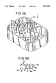
- FIG. 9 is a cross-sectional view along
- FIG. 9A is a cross-sectional view of alternative construction to that shown along line 9--9 in FIG. 7;
- FIG. 10 is a cross-sectional view along line 10--10 in FIG. 5;
- FIG. 11 is a perspective top view of a separate connector for use with the pallet of FIGS. 1-10;
- FIG. 11A is a perspective top view of an alternative separate connector for use with the pallet of FIGS. 1-10;
- FIG. 12 is a top plan view of the connector of FIG. 11;
- FIG. 13 is a bottom plan view of the connector of FIGS. 11-12;
- FIG. 14 is a right elevation view of the connector of FIGS. 11-13, the left elevation view being a mirror image thereof;
- FIG. 15 is a front elevation view of the connector of FIGS. 11-14, the rear elevation view being a mirror image thereof.
- FIG. 16 is a top plan detailed view of the integral internal connector of the base
- FIG. 17 is a cross-sectional view of the integral internal connector of FIG. 16;
- FIG. 18 is a bottom plan detailed view of the integral internal connector of the deck.
- FIG. 19 is a cross-sectional view of the integral internal connector along line 19--19 of FIG. 18;
- FIG. 20 is a cross-sectional view of the integral internal connector of along line 20--20 in FIG. 7.
- FIGS. 1-3 of the drawings show a plastic pallet, generally designated by reference numeral 10, having three primary components.
- the components are a base 20, a deck 100 and a plurality of connectors 11.
- the connectors 11, interconnecting the deck and base, are specially designed so the pallet can be assembled without the need for specially designed tools, and the connectors can be snap-fitted onto the deck and base.
- the pallet incorporates six (6) separate connectors 11 and six (6) integral connectors 11a.
- Both the deck and the base have openings which define surrounding abutments recessed below the exposed surface and the connectors (separate and integral) have flexible tangs with barbs which engage the abutments.
- the pallet 10 has opposed sides 13 and opposed ends 14.
- the separate connectors 11 are shown positioned at the four corners of the base and deck members and midway along each opposed end 14.
- Integral connectors or connection means 11a are built into the base and deck of the pallet along the sides 13 between the corners and in internal rows parallel to the ends 14.
- the connectors 11, 11a are positioned so forklift tines can be inserted into side channels 15 and end channels 16 for lifting and moving the assembled pallet and the palletized goods.
- the six separate connectors are positioned where, it has been found, there are the highest probabilities of potential damage. Specifically, misdirected loads fall upon or misaligned forklift contact the corner areas most frequently. Thus, broken connectors located in these areas can be easily removed and replaced.
- the six separate connectors are positioned with one in each corner and one between the corners, on the short side, here the ends 125, 126 of the pallet.
- the integral connectors are placed along the long side, here the sides 123, 124 of the pallet, to allow a longer side.
- the extra internal supports permit the overall size of the pallet to be larger than prior pallets. They reduce the distance between connectors, minimizing "bowing" due to the weight of the load being supported.
- the connectors 11, 11a are oriented and sized so that the forklift tines can be inserted into either side or end and pass, without obstruction, through the pallet. See FIG. 7, wherein the orientation of the connectors is shown and the distances, designated X and Y, for the channels 15, 16 is shown.
- the base 20 of the present invention is used below the deck 100 and while in use generally rests on the ground or floor. Because goods are not normally placed directly on the base 20, it is not a flat, continuous surface, rather it is much like a frame structure.
- the base supports the deck above the flooring.
- the base has two surfaces, namely an inner surface 21 (FIG. 5) and an outer surface 22 (FIG. 4).
- the outer surface 22 is the surface that faces out from the pallet; the surface that faces down and contacts the ground or floor when the pallet is constructed.
- the inner surface 21 is the surface facing the inside of the pallet, i.e., the surface the connectors are attached to and the surface facing the deck.
- the base 20 is generally rectangular in shape. It has a first side 23, an opposed second side 24, a first end 25 and an opposed second end 26.
- the base structure itself includes a pair of substantially parallel side members 31 and a plurality of openings 17 therein (positioned at the four corners and midway along each end member 32) for receiving the separate connectors 11.
- a pair of substantially parallel end members 32 substantially perpendicular and connected to the side members 31 are provided.
- the end members 32 have an opening 17 therein at their corners and midway therein for receiving the separate connectors 11.
- a first cross member 33 parallel the side members 31 with openings 17 at each end for receiving the separate connectors 11 is disposed between and connected to the end members 32.
- a second cross member 34a and third cross member 34b, both parallel the end members 32, are disposed between and connected to the side members 31.
- FIG. 10 there is shown a cross section of an end member 32, which is similar to a side member 31 and cross member 33, 34a, 34b.
- the end members 32 like the side members 31 and cross members 33, 34a, 34b, are generally U-shaped in cross-section.
- the end member 32 has two horizontal longitudinal portions 41 which are integral with upwardly projecting, substantially vertical longitudinal portions 42 which, in turn, are connected to a centrally located second horizontal longitudinal portion 43.
- This second horizontal longitudinal portion 43 is positioned above the first horizontal longitudinal portions 41 adjacent the sides.
- the concave surface formed by the upwardly projecting longitudinal portions 42 and second horizontal longitudinal portion 43 of the end members (and the side members and cross members) is the outer surface 22.
- each vertical transverse portion 50 terminates at a vertical longitudinal portion 42.
- Holes 51 are formed between the vertical longitudinal portions 42 and each intermediate longitudinal portion 44 and between the intermediate longitudinal portions 44 in the space between the vertical transverse portions 50.
- the inner surface 21 (FIG. 5) is relatively smooth and U-shaped with the plurality of spaced, parallel transverse inner ribs 38 integral with the inner surfaces of the first horizontal longitudinal portion 41, upwardly projecting longitudinal portions 42 and the second horizontal longitudinal portion 43.
- the innermost surface 38a of the transverse inner ribs 38 act as guides or ramps for the forklift tines. Thus, if a tine hits the inclined surface 38a, rather than pushing the pallet, it will slide along the incline to its proper position.
- openings 17 are formed by sleeves and spokes built at the corners and midway along the end member 32 at the point where the first cross member 33 intersects thereto of the base 20 for cooperating therewith.
- the base 20 has openings 17 adapted to receive the tangs of the connectors 11.
- the openings 17 are surrounded by circular, outer recessed abutments 61 that are recessed below the plain of the adjacent outer surface 62, 22 of the base.
- the recessed abutments 61 are formed by a substantially vertical first annular wall 64 and a substantially vertical second annular wall 65.
- the outer recessed abutments 61 are generally circular and connected along with the first and second annular walls 64, 65 by spokes 63 to the vertical transverse and longitudinal portions 42, 44, 50 (FIG. 5).
- substantially vertical guide walls or posts 66 are formed into the base 20 in the inner surface 21 thereof.
- the guide walls 66 are contoured to follow the external corner surfaces of the connectors.
- the first horizontal longitudinal portion 41 and the transverse inner ribs 38 are replaced by vertical support walls 67.
- the connectors are seated on these vertical support walls 67 and the guide walls 66 project therefrom.
- the connectors 11, discussed in detail below, can thus be snapped into the base, on and adjacent to the inner surface 21, by applying axial force to the connectors so the barbs of the connectors will snap into position onto the outer recessed abutment 61. With this construction, the barbs will not extend out beyond the outer plain of the outer surface 22.
- the pallet base has a circular support wall 69 projecting outwardly from the outer surface 22 adjacent each of the corner connector openings 17.
- ports 68 are provided for adding molten plastic under pressure to the mold for making the bases. Excess molding material around the ports 68 can be cut, sanded or scraped off the final product.
- X-shaped ribs 70 are formed projecting outwardly from the outer surface 22 of the base 20 adjacent the internal connectors (320).
- the base 20 is connected, via separate connectors 11 and integral connectors 11a, to a deck 100 (shown in FIGS. 1-3, 6, 7, 8, 9 and 9A). It is the deck the goods are placed on.
- the deck 100 has two surfaces, namely an inner surface 121 (FIG. 7) and an outer surface 122 (FIG. 6).
- the outer surface 122 is the surface which faces out from the pallet; specifically it is the surface which faces up and contacts the goods being palletized.
- the inner surface 121 is the surface facing the inside of the pallet, i.e., the side the connectors are attached to, and the base 20.
- the deck 100 is generally rectangular in shape. It has a first side 123, an opposed second side 124, a first end 125 and an opposed second end 126.
- the outer surface 122 is substantially planar and includes perimeter reinforcement means.
- the end perimeter reinforcement means and side reinforcement means are similar and (FIG. 9) includes a substantially vertical perimeter first outer wall 131 and a first inclined outer wall 132 integral with a second inclined outer wall 133.
- the first inclined outer wall 132 includes a drain 134.
- Spaced and parallel intermediate transverse walls 135 are integral with and bridge the perimeter first outer wall 131 and the planar section of the inner surface 121.
- the side and end perimeter reinforcement means may be configured to include a substantially vertical perimeter first outer wall 131a and an integral substantially vertical second outer wall 133a, the second outer wall extending out further from the base of the planar inner surface 121 of the base 100 a further distance than the first outer wall.
- Spaced and parallel intermediate transverse walls 135a or gussets having an inclined, exposed surface 135b integral with and bridge the two perimeter outer walls 131a, 133a and the planar section of the inner surface. In this construction, no drain is necessary.
- FIG. 9A has been shown to be stronger than the first embodiment, FIG. 9, in taking repeated, external strike forces thereto.
- Both the side and the end perimeter reinforcement means are hooked-shape (FIG. 9) or U-shaped (FIG. 9A) in cross-section.
- the concave surface of the reinforcement means is the outer surface 122 in the hook-shaped design (FIG. 9) and the inner surface in the U-shaped design (FIG. 9a).
- the first inclined outer walls 132 or the combination of the first and second outer walls 131a, 133a with the inclined surface 135b of the transverse walls 135a act as guides or ramps for the forklift tines. Thus, if a tine hits the inclined wall, rather than pushing the pallet, it will slide along the incline to its proper position.
- the inner surface 121 of the deck has a reinforcement structure projecting outwardly therefrom.
- This reinforcement structure includes a plurality of cells 151 formed by a plurality of parallel end walls 152 and a plurality of side walls 153.
- the cells 151 are substantially rectangular and, apart from the perimeter cells 151a, the cells 151 are approximately the same size.
- the matrix formed by the end walls 152 and side walls 153 is shown in FIG. 7. Most of the perimeter cells 151a include a second end wall 152a between the end walls 152 and a second side wall 153a between the side walls 153.
- openings 117 are formed by sleeves and spokes built at the corners and midway along the ends 125, 126 of the deck 100 for cooperating therewith.
- the openings 117 are adapted to receive the tangs of the connectors 11.
- the openings 117 are also surrounded by circular, outer recessed abutments 161 that are recessed below the plain of the adjacent outer surface 122 of the base.
- the recessed abutments are formed by and between a substantially vertical first annular wall 164 and a substantially vertical second annular wall 165.
- the outer recessed abutments 161 are generally circular and connected along with the first and second annular walls 164, 165 by spokes (in the form of webs) 163 to the substantially vertical perimeter first outer wall 131 and the end walls 152 or the side walls 153.
- substantially vertical guide walls or posts 166 are formed into the deck 100 in the inner surface 121 thereof. These guide walls also prevent the connectors from being knocked out of position by misaligned forklift tines.
- the guide walls 166 are contoured to follow the external corner surfaces of the connectors. Upwardly projecting teeth 166a may also be used to assist in guiding the connectors and preventing them from getting knocked out of place when contacted. The sleeve of the connector being positioned between the teeth 166a and the guide walls 166.
- the channels 15, 16 are kept unobstructed within the pallet.
- the connectors 11, 11a are oriented and sized so the forklift tines can be inserted into either side or end and pass, without obstruction, through channels of a predetermined width, designated X and Y, in the pallet.
- the connectors 11 can thus be snapped into the deck, on and adjacent to the inner surface 121, by applying axial force to the connectors so the barbs of the connectors will snap into position onto the outer recessed abutment 161. With this construction, the barbs will not extend out beyond the outer plain of the outer surface.
- centrally located central side walls 153a generally bisecting the cells 151 and centrally located central end walls 152a along and between the intermediate openings along the ends.
- most of the cells 151 include apertures 155 for drainage and to reduce the amount of material used. To avoid the problem of having goods falling through the deck, the apertures are not large.
- the pallet deck has a circular support wall 158 projecting outwardly from the inner surface 121.
- Spokes 158a project inwardly from the circular support wall 158 and terminate at a circular sleeve 158b for permitting rubber pads to be placed on the opposite surface.
- rubber pads may be secured in the spaces designated 159 (formed by the circular support wall 158 and the circular sleeve 158b shown on the inner surface) onto the outer surface 122.
- These pads (159) near the corners can protect the base while it is stored and stacked. The pads also assist in preventing the goods resting on the outer surface of the deck from slipping.
- the opposite surface FIG.
- pads 159 are provided on the inner surface. These pads 159, in which there are four, contact the forklift tines that pass between the connectors into either the side channels 15 or the end channels 16. Thus, if the forklift stops abruptly, the pads will prevent the pallet from slipping on the tines.
- the cells 151 diagonally adjacent the openings 117 at the corners of the deck 100 include a diagonal intermediate cross wall 171.
- the cells diagonally adjacent these cells 151 with a diagonal intermediate cross member 171 include four inclined cross walls 172 projecting inwardly from the corners of the cell.
- An additional inclined cross wall 173 is present in a further cell adjacent the one with the four inclined cross walls 172.
- the additional walls act as channels, additional channels, to facilitate the flow of the molten, pressurized plastic through the mold and to reduce the natural resistance to such flow.
- ports 168 Directly opposite the four inclined cross walls 172 of the inner surface 121, on the outer surface 122, are ports 168 for adding molten plastic under pressure to the mold for making the decks. Excess molding material around the ports 168, like the ports 68 for the base, can be cut, sanded or scraped off the final product.
- Each connector 11 includes a hollow central circular core 220 that has circumferentially spaced slots 222 extending from opposite ends thereof which produce first and second sets of tangs 224, 226.
- Each tang 224, 226 is identical in construction and has a barb 230 formed adjacent the free, distal end thereof.
- Each barb 230 has a flat lower surface 232 which extends perpendicular to the axis of the core 220 and has a tapered outer surface 234 extending from the outer edge to define a ramp.
- each set 224, 226 with each tang spanning approximately ninety degrees.
- the tangs of the respective sets 224, 226 are circumferentially offset so the slots forming one set of tangs 224 are axially aligned with the centers of the opposite set of tangs 226 (FIGS. 14 and 15).
- the central core 220 also has a force absorbing flange 236 located at the center of the core 220 and equally spaced from the two ends. Forces applied to the tangs are transmitted to the flange 236 where they are dissipated.
- the connector 11 also includes a large rectangular sleeve 244 surrounding the core 220 and is connected thereto by radially extending spokes 246 and transverse spokes 247.
- the radial spokes 246 project from the core 220 at locations between the slots 222 forming the tangs 224, 226 (FIGS. 12 and 13).
- the radial spokes 246 are radially spaced from each other, as shown in FIG. 12, at three different angles, that being angle A, angle B and angle C. In the embodiment shown, angle A is 50 degrees, angle B is 45 degrees and angle C is 35 degrees.
- the angles for the radial spokes 246 are designed so the spoke absorbs external, inwardly directed forces to the outer sleeve 244. In practice, it has been found that forces caused by misaligned forklift tines striking the connectors, are resisted better when the radial spokes are oriented as shown.
- angle B increases the distance between the spokes at each spoke's junction with the sleeve.
- the widening in distance between supports translates to an increase in the risk of breakage between supports.
- the number of spokes may be increased, however, this adds to weight and amount of material used and to further complications in the molding process. Accordingly, a balance is made between these factors.
- the transverse spokes 247 add transverse support to the radial spokes 246 and assist in distributing forces applied to the sleeves 244.
- the transverse spokes 247 also assist in minimizing the movement, and thus the weakening, of the radial supports 246.
- FIG. 11A shows a connector 11 with a different transverse spoke 247.
- the upper and lower edges of the spokes 246, 247 and the sleeve 244 define planes P (FIG. 15) which extend perpendicular to the axis of the core 220.
- the openings 17 in the base 20 and the deck 100 are adapted to receive the tangs 224, 226.
- Each opening 17 is surrounded by an abutment 61, 161 recessed below the adjacent surface of the deck or the base.
- the abutment 61, 161 is sized such that the distance between the plane P and the flat lower surface 232 of the barb 230 allows the barbs to snap into position (See FIG. 8).
- the connectors 11 are first assembled to a first piece, either the base 20 or the deck 100, by aligning a set of tangs 224, 226 with the opening 17 and then applying an axial force which causes the ramps 234 of the barbs 230 to deflect the tang inwardly sufficient to allow the set of tangs to pass through the openings. After the barb 230 has cleared the abutment surface 61, 161, the memory characteristics of the plastic will snap the tangs back to their original condition and lock the connector to the base or deck. After all the connectors are assembled on the base or deck, the other piece, i.e., deck or base, is positioned above or below the piece with the connectors and the openings therein are aligned. A force applied to the outer surface of the second piece will similarly snap the connectors to the second piece.
- FIGS. 16-20 The details of the integral internal connectors of the base and the deck are shown in FIGS. 16-20.
- the six integral connectors 11a are positioned on the base 20 of the embodiment shown in two parallel rows with one (1) at each of the junctions where the second cross member 34a and the third cross member 34b meets each of the side members 31 and one (1) each at the junction of where the first cross member 33 meets the second cross member 34a and the third cross member 34b.
- the six integral connectors 11a are positioned on the deck 100 (FIG. 7) of the embodiment shown in two parallel rows between and parallel the two ends 125, 126, four (4) adjacent the sides 123, 124 (two sets--one set per side) and two disposed between each set.
- the integral connectors comprise a mating system.
- the system of the base cooperates with the system of the deck.
- the system of the base 20 includes a hollow central circular core 320 which has circumferentially spaced slots 322 extending from the distal end thereof which produce a set of tangs 328.
- Each tang 328 is identical in construction and has a barb 330 formed adjacent the distal end thereof.
- Each barb 330 has a flat lower surface 332 which extends perpendicular to the axis of the core 320 and has a tapered outer surface 334 extending from the outer edge to define a ramp.
- each tang 228 is shown with each tang spanning approximately ninety degrees.
- the central core 220 is attached by crossing integral spokes or webs 321 via a cylindrical web 323 to the main body of the base 20.
- the system of the deck 100 includes a protective force absorbing oval sleeve 330 with inwardly projecting webs or spokes 331 and an internal, central receiving core 332.
- the central receiving core 332 has an opening 333 at the distal end thereof.
- adjacent the outer surface 122 of the deck 100 there are circular, outer recessed abutments 361 which are recessed below the plain of the adjacent outer surface 122 of the base.
- the recessed abutments are formed by and between a substantially vertical first annular wall, the central receiving core 322, and a substantially vertical second annular wall 365.
- the outer recessed abutments 361 are generally circular.
- the recessed abutment 361 sitting below the adjacent outer surface 122 of the deck is sized so it is greater than or equal to the distance between the flat lower surface 332 of the barb 330 and the outermost point of the taper or ramp 334. This allows the barbs to snap into position and sit below the outer surface 122 of the deck. (See FIG. 8).
- tabs 335 are formed at the distal end of the central receiving core to guide the tangs therein.
- the central receiving core 332 with the opening 333 at the distal end thereof is sized so as to receive the central core 320 with tangs 328 of the base 20.
- the integral connectors 11a are aligned such that the central cores 320 of the base 20 face the receiving cores 332 of the deck 100.
- An axial force is applied to the connectors 11a which causes the ramps 334 of the barbs 330 to deflect the tangs inwardly sufficient to allow the tangs to pass through and within the opening 333 of the receiving core 332.
- the memory characteristics of the plastic will snap the tangs back to their original condition and lock the connector together. This can be done simultaneously with the attachment of the separate connectors 11.
- the two centrally located internal, integrated connectors 11a (FIG. 7) on the deck 100 also have projecting barbs 350.
- a projecting post 354 is formed which supports the barb.
- Each barb 350 has at its distal end a flat lower surface 352 and ramp or taper 353.
- these centrally located connectors are larger in size and include additional internal transverse support ribs 351.
- support webs 355 assist in reinforcing the posts 354.
- These projecting barbs 350 of the posts 354 cooperate with small holes, designated 370 (shown in FIGS. 4 and 5), formed into the base 20.
- the holes 370 receive the post 354 and ramp section 353 of the barbs 350 and slide into a snap fit relationship with the application of an axial force. This additional locking mechanism is for added safety. If for any reason other connectors were to fail, the additional posts 354 and barbs 350 act to keep the components together.
- the two primary pallet components namely the base and the deck, are preferably injection molded from recycled material, such as polypropylene or similar thermoplastic material. Additionally, a pigment may be added to provide color combinations to suit the customer's needs.
- the intricate design of the connectors has several distinct advantages.
- the design is such that all external forces are transmitted to the center of the core, which will withstand the greatest force without destruction.
- the connectors are configured so they can be formed as one piece in a single stage mold to reduce the cost. Since the connectors and the decks are preferably injection molded from recycled plastic, the costs are further reduced.
- Another significant advantage of the plastic pallet is that the connectors can easily be separated should one of the connectors become damaged. This can be accomplished by the owner without return of the pallet assembly to the manufacturer.
Abstract
Description
Claims (22)
Priority Applications (13)
| Application Number | Priority Date | Filing Date | Title |
|---|---|---|---|
| US08/351,894 US5579686A (en) | 1988-08-09 | 1994-12-08 | Plastic pallet assembly |
| PCT/US1995/015896 WO1996017783A1 (en) | 1994-12-08 | 1995-12-07 | Plastic pallet assembly |
| ES95942580T ES2117883T3 (en) | 1994-12-08 | 1995-12-07 | PLASTIC LOADING PLATFORM ASSEMBLY. |
| MX9704199A MX9704199A (en) | 1994-12-08 | 1995-12-07 | Plastic pallet assembly. |
| CN95197541A CN1175233A (en) | 1994-12-08 | 1995-12-07 | Plastic pallet assembly |
| PL95320641A PL180388B1 (en) | 1994-12-08 | 1995-12-07 | Set of plastic pallets |
| DE1995602966 DE69502966T2 (en) | 1994-12-08 | 1995-12-07 | PLASTIC RANGE |
| RU97109835A RU2151088C1 (en) | 1994-12-08 | 1995-12-07 | Plastic pallet |
| EP19950942580 EP0796203B1 (en) | 1994-12-08 | 1995-12-07 | Plastic pallet assembly |
| AT95942580T ATE167140T1 (en) | 1994-12-08 | 1995-12-07 | PLASTIC PALLET |
| AU43761/96A AU4376196A (en) | 1994-12-08 | 1995-12-07 | Plastic pallet assembly |
| BR9509881A BR9509881A (en) | 1994-12-08 | 1995-12-07 | Plastic palette set |
| CA 2207281 CA2207281C (en) | 1994-12-08 | 1995-12-07 | Plastic pallet assembly |
Applications Claiming Priority (8)
| Application Number | Priority Date | Filing Date | Title |
|---|---|---|---|
| US07/230,025 US4843976A (en) | 1988-08-09 | 1988-08-09 | Plastic pallet |
| US07/644,928 US5197395A (en) | 1988-08-09 | 1991-01-23 | Plastic pallet with deck assembly |
| US07/961,396 US5343814A (en) | 1988-08-09 | 1992-10-15 | Plastic pallet assembly |
| US29/007,372 USD346681S (en) | 1993-04-21 | 1993-04-21 | Two part interlocking plastic pallet |
| US29/012,508 USD347511S (en) | 1993-09-02 | 1993-09-02 | Two part interlocking plastic pallet assembly |
| US29/015,696 USD354606S (en) | 1993-11-24 | 1993-11-24 | Connector for a pallet assembly |
| US29/024,050 USD364030S (en) | 1994-06-07 | 1994-06-07 | Plastic pallet assembly |
| US08/351,894 US5579686A (en) | 1988-08-09 | 1994-12-08 | Plastic pallet assembly |
Related Parent Applications (2)
| Application Number | Title | Priority Date | Filing Date |
|---|---|---|---|
| US29015696 Continuation-In-Part | 1993-11-24 | ||
| US29024050 Continuation-In-Part | 1994-06-07 |
Related Child Applications (1)
| Application Number | Title | Priority Date | Filing Date |
|---|---|---|---|
| US29033574 Continuation-In-Part | 1995-01-17 |
Publications (1)
| Publication Number | Publication Date |
|---|---|
| US5579686A true US5579686A (en) | 1996-12-03 |
Family
ID=23382873
Family Applications (1)
| Application Number | Title | Priority Date | Filing Date |
|---|---|---|---|
| US08/351,894 Expired - Lifetime US5579686A (en) | 1988-08-09 | 1994-12-08 | Plastic pallet assembly |
Country Status (12)
| Country | Link |
|---|---|
| US (1) | US5579686A (en) |
| EP (1) | EP0796203B1 (en) |
| CN (1) | CN1175233A (en) |
| AT (1) | ATE167140T1 (en) |
| AU (1) | AU4376196A (en) |
| BR (1) | BR9509881A (en) |
| DE (1) | DE69502966T2 (en) |
| ES (1) | ES2117883T3 (en) |
| MX (1) | MX9704199A (en) |
| PL (1) | PL180388B1 (en) |
| RU (1) | RU2151088C1 (en) |
| WO (1) | WO1996017783A1 (en) |
Cited By (52)
| Publication number | Priority date | Publication date | Assignee | Title |
|---|---|---|---|---|
| US5967057A (en) * | 1996-11-05 | 1999-10-19 | Nippon Plapallet Company | Synthetic resin pallet |
| US6021721A (en) * | 1995-03-14 | 2000-02-08 | World Wide Pallets Limited | Pallet |
| US6109190A (en) * | 1999-10-19 | 2000-08-29 | Plastic Pallet Production, Inc. | Materials handling pallet |
| US6234087B1 (en) | 2000-01-21 | 2001-05-22 | Alltrista Corporation | Machine dispensed modular pallet |
| USD443969S1 (en) | 1999-10-22 | 2001-06-19 | Rehrig Pacific Company | Pallet |
| US6250234B1 (en) | 1998-07-01 | 2001-06-26 | Rehrig Pacific Company | Method of reinforcing a plastic pallet |
| US6283044B1 (en) | 1998-07-01 | 2001-09-04 | Rehrig Pacific Company | Pallet assembly |
| WO2001064526A2 (en) * | 2000-02-28 | 2001-09-07 | Harout Ohanesian | Thermoplastic pallet |
| US6416271B1 (en) * | 2000-04-07 | 2002-07-09 | Nucon Corporation | Drop box container |
| US6564725B2 (en) | 2001-01-05 | 2003-05-20 | Ronald G. Hale | Load supporting platform |
| US20030121816A1 (en) * | 2001-12-27 | 2003-07-03 | Pigott Maurice J. | Palletized tray system |
| US6705237B2 (en) | 2000-08-24 | 2004-03-16 | Infiltrator Systems, Inc. | Plastic pallet design |
| US20040058558A1 (en) * | 2002-07-11 | 2004-03-25 | Hitomi Sakurai | Manufacturing method for a semiconductor device |
| EP1529733A1 (en) * | 2003-11-06 | 2005-05-11 | GEBHARDT Transport- und Lagersysteme GmbH | Wheeled platform |
| US20050145145A1 (en) * | 2003-04-28 | 2005-07-07 | Ogburn Sean T. | Pallet Assembly |
| US20050166804A1 (en) * | 2004-01-29 | 2005-08-04 | Hansen Peter J. | Pallet constructed of rubber composite |
| US20050217543A1 (en) * | 2004-04-06 | 2005-10-06 | Sue-Tsen Hung | Tool cabinet fixing and supporting structure |
| US20060032413A1 (en) * | 2004-07-29 | 2006-02-16 | Ogburn Sean T | Pallet |
| US20060201400A1 (en) * | 2005-02-18 | 2006-09-14 | Moore Roy E Jr | Plastic pallet having deck suspension system |
| US20060260517A1 (en) * | 2000-08-24 | 2006-11-23 | Moore Roy E Jr | Plastic pallet having replaceable deck |
| US20070256609A1 (en) * | 2006-05-08 | 2007-11-08 | Chep Usa. | Durable Pallet and Pallet Block |
| US20070277706A1 (en) * | 2006-06-01 | 2007-12-06 | Carter Bruce R | Load bearing structure with inserts |
| US20080271647A1 (en) * | 2007-05-02 | 2008-11-06 | Brett Boag | Pallet |
| US20090241461A1 (en) * | 2008-03-28 | 2009-10-01 | Linares Miguel A | Composite stackable pallet construction |
| US20090246461A1 (en) * | 2008-03-28 | 2009-10-01 | Oria Collapsibles, Llc | Article, assembly and process for producing a waterproof, degradation resistant and increased structural supported stiffener insert such as incorporated into a composite pallet construction |
| US7690315B2 (en) | 2007-06-15 | 2010-04-06 | Rehrig Pacific Company | Nestable pallet |
| US7779765B2 (en) | 2006-03-03 | 2010-08-24 | Daniel Kelly | Pallet with telescoped leg assemblies |
| US20110179977A1 (en) * | 2008-06-20 | 2011-07-28 | Oria Collapsibles, Llc | Pallet assembly with locating support structure |
| US8146516B2 (en) | 2008-03-28 | 2012-04-03 | Oria Collapsibles, Llc | Structural supporting substrate incorporated into a composite and load supporting platform |
| US8438981B2 (en) | 2008-06-20 | 2013-05-14 | Oria Collapsibles, Llc | Pallet design with buoyant characteristics |
| US20130195547A1 (en) * | 2010-07-30 | 2013-08-01 | Widee B.V. | Modular construction system, construction element, coupling element, end element and tool for use in such a construction system |
| US8522694B2 (en) | 2008-06-20 | 2013-09-03 | Oria Collapsibles, Llc | Structural supporting pallet construction with improved perimeter impact absorbing capabilities |
| US8701569B2 (en) | 2008-06-20 | 2014-04-22 | Oria Collapsibles, Llc | Pallet design with structural reinforcement |
| US8770115B2 (en) | 2012-02-14 | 2014-07-08 | Rehrig Pacific Company | Pallet assembly |
| US20150147112A1 (en) * | 2010-07-13 | 2015-05-28 | A.R. Arena Products, Inc. | Flex assembly of pallet base and deck |
| US9073451B1 (en) * | 2014-05-12 | 2015-07-07 | Adam J. Wurzer | Truck seat adapter |
| US20160264293A1 (en) * | 2015-03-10 | 2016-09-15 | Orbis Corporation | Repairable bulk bin base or pallet |
| USD774271S1 (en) * | 2014-04-16 | 2016-12-13 | Georg Utz Holding Ag | Pallet |
| US10081454B2 (en) * | 2016-11-21 | 2018-09-25 | Chep Technology Pty Limited | Plastic pallet with support blocks having pockets for pin wheeling and associated methods |
| US10081453B2 (en) * | 2016-11-21 | 2018-09-25 | Chep Technology Pty Limited | Plastic pallet with support blocks having upper towers and associated methods |
| US10093448B2 (en) * | 2016-11-21 | 2018-10-09 | Chep Technology Pty Limited | Plastic pallet with support blocks having inner and outer blocks and associated methods |
| WO2019231885A1 (en) * | 2018-05-31 | 2019-12-05 | Chep Technology Pty Limited | Repairable plastic pallet with removable support blocks and associated methods |
| US10532852B2 (en) | 2017-06-13 | 2020-01-14 | Rehrig Pacific Company | Fire retardant pallet assembly |
| US10661944B2 (en) | 2016-10-11 | 2020-05-26 | Rehrig Pacific Company | Pallet with inset deck |
| USD899725S1 (en) * | 2016-03-31 | 2020-10-20 | PALLcon Services Company, Ltd. | Pallet with columns |
| US10947008B2 (en) * | 2017-06-14 | 2021-03-16 | Logicpalet World, S.L. | Detachable pallet |
| USD932729S1 (en) | 2019-07-23 | 2021-10-05 | Signode Industrial Group Llc | Pallet |
| CN113602630A (en) * | 2021-09-10 | 2021-11-05 | 广东特帅科技股份有限公司 | Combined plastic pallet |
| USD942109S1 (en) * | 2020-04-06 | 2022-01-25 | Southwest Agri-Plastics, Inc. | Pallet |
| US11352169B2 (en) | 2019-01-18 | 2022-06-07 | Rehrig Pacific Company | Pallet assembly |
| US11465802B2 (en) * | 2016-08-21 | 2022-10-11 | Remcon Plastics, Inc | Pallet having curved openings |
| USD982877S1 (en) * | 2020-12-07 | 2023-04-04 | Monoflo International, Inc. | Pallet corner |
Families Citing this family (10)
| Publication number | Priority date | Publication date | Assignee | Title |
|---|---|---|---|---|
| JP4572899B2 (en) * | 2005-06-24 | 2010-11-04 | Dic株式会社 | Plastic pallet |
| ES2333840B1 (en) * | 2009-06-10 | 2011-02-11 | Ribawood, S.A. | PALLET |
| US8671848B2 (en) | 2011-08-04 | 2014-03-18 | Wayne Randall | Pallet protector device and method |
| CN102887264A (en) * | 2012-09-29 | 2013-01-23 | 苏州同大机械有限公司 | Tray |
| CN103770997B (en) * | 2012-10-24 | 2016-12-21 | 珠海格力电器股份有限公司 | Board |
| CN102991814B (en) * | 2012-11-29 | 2015-07-08 | 上海派瑞特塑业有限公司 | Plastic tray |
| CN104097912B (en) * | 2013-04-07 | 2016-05-04 | 格力电器(郑州)有限公司 | Board |
| CN103723336B (en) * | 2013-11-22 | 2016-08-17 | 开平雅琪塑胶机械模具厂 | A kind of pallet apparatus |
| WO2017066900A1 (en) * | 2015-10-19 | 2017-04-27 | 吕尚文 | Improved pallet structure |
| CN109319249B (en) * | 2018-09-04 | 2020-01-17 | 宁波均创智能科技有限公司 | Material box for anti-collision bearing roller charging method |
Citations (97)
| Publication number | Priority date | Publication date | Assignee | Title |
|---|---|---|---|---|
| GB166486A (en) * | ||||
| US2691499A (en) * | 1950-04-03 | 1954-10-12 | Fleming & Sons Inc | Load supporting pallet |
| US2916239A (en) * | 1955-02-02 | 1959-12-08 | Stopps Alfred Leslie | Nesting pallets |
| US2918241A (en) * | 1954-11-22 | 1959-12-22 | Edwin C Maher | Fabricated pallet and spacer therefor |
| US2991965A (en) * | 1959-03-23 | 1961-07-11 | Mag Craft Corp | Pallet |
| US3123020A (en) * | 1964-03-03 | Disposable pallet structure | ||
| US3307504A (en) * | 1965-12-01 | 1967-03-07 | Nosco Plastics | Pallet |
| US3316861A (en) * | 1966-04-06 | 1967-05-02 | Interstate Container Corp | Pallet foot |
| US3407758A (en) * | 1966-05-20 | 1968-10-29 | Continental Can Co | Expendable pallets |
| US3424110A (en) * | 1967-02-03 | 1969-01-28 | William W Toot | Pallet |
| US3438342A (en) * | 1967-04-18 | 1969-04-15 | Woodstream Corp | Material-handling pallet and improved pallet leg or support and load-distributing attachment therefor |
| US3606844A (en) * | 1969-10-30 | 1971-09-21 | Standard Oil Co | Pallet having guiding means in all sides |
| US3610173A (en) * | 1969-04-04 | 1971-10-05 | John W Mcilwraith | Plastic pallet |
| FR2101346A5 (en) * | 1970-08-06 | 1972-03-31 | Ver Deutsche Metallwerke Ag | |
| US3664272A (en) * | 1970-06-10 | 1972-05-23 | Skid Stack Corp | Stackable pallet constructions |
| US3664271A (en) * | 1969-12-15 | 1972-05-23 | Ernest Harold Wolder | Plastic molded pallet |
| US3667403A (en) * | 1970-06-11 | 1972-06-06 | Pack Rite Packaging & Crating | Pallet |
| AU2332870A (en) * | 1969-12-15 | 1972-06-15 | Ernest H. Wolder James H. Jarrett | An improved pallet |
| US3680495A (en) * | 1970-10-12 | 1972-08-01 | Hi Line Plastics Inc | Pallet structure |
| US3683821A (en) * | 1970-09-24 | 1972-08-15 | Robert T Mangold | Pallet |
| US3685461A (en) * | 1970-10-30 | 1972-08-22 | Owens Illinois Inc | Pallet |
| US3691965A (en) * | 1966-12-06 | 1972-09-19 | Nosco Plastics | Pallet |
| US3691964A (en) * | 1970-10-19 | 1972-09-19 | Crown Zellerbach Corp | Pallet |
| US3717396A (en) * | 1969-11-18 | 1973-02-20 | H Dupree | Modular shell cabinet structure |
| GB1310898A (en) * | 1969-08-19 | 1973-03-21 | Dale Ltd John | Pallets |
| FR2160677A1 (en) * | 1971-11-19 | 1973-06-29 | Buehler Ag Geb | |
| AU4208672A (en) * | 1971-05-24 | 1973-11-15 | Hooke L G | Improvements in load supporting pallets |
| US3804032A (en) * | 1972-10-02 | 1974-04-16 | L Baucom | Pallet and pallet leg |
| US3814031A (en) * | 1972-05-26 | 1974-06-04 | Monsanto Co | Plastic pallets |
| US3835791A (en) * | 1972-09-07 | 1974-09-17 | D Brown | Press-on pallet support |
| US3835792A (en) * | 1971-04-05 | 1974-09-17 | T Wharton | Pallet construction |
| US3868915A (en) * | 1971-12-29 | 1975-03-04 | Erich Hafner | Pallets |
| DE2403374A1 (en) * | 1974-01-24 | 1975-08-07 | Schoeller & Co Ag A | PLASTIC PALLET |
| FR2259023A1 (en) * | 1974-01-24 | 1975-08-22 | Schoeller & Co Ag A | |
| US3915099A (en) * | 1972-10-02 | 1975-10-28 | Wonder Ind Inc | Support column and disposable pallet structure |
| US3916803A (en) * | 1973-10-02 | 1975-11-04 | Emilia Miguel Garcia | Loading platform |
| FR2274512A1 (en) * | 1974-06-17 | 1976-01-09 | Phoenix Houtind Bv | HANDLING PALLET |
| US3994241A (en) * | 1975-10-06 | 1976-11-30 | Keyrack Company, Inc. | Removable stacking frame assembly for pallets |
| US4002126A (en) * | 1974-11-11 | 1977-01-11 | Said Thomas N. Depew, By Said Ferris Andrew Bell | Pallet construction |
| DE2655593A1 (en) * | 1975-12-09 | 1977-06-16 | Wavin Bv | PLASTIC PALLET |
| US4051787A (en) * | 1975-05-06 | 1977-10-04 | Mitsubishi Chemical Industries Ltd. | Plastic pallet |
| USD247523S (en) | 1976-12-02 | 1978-03-14 | Phillips Petroleum Company | Bakery container or the like |
| US4128253A (en) * | 1977-10-14 | 1978-12-05 | Powers Richard J | Pallet and roller post construction therefor |
| US4159592A (en) * | 1978-01-10 | 1979-07-03 | Matrix Toys, Inc. | Close coupling strut for construction set having clip fasteners |
| SU701869A1 (en) * | 1978-05-10 | 1979-12-05 | Киевское Городское Производственное Объединение Грузового Автотранспорта | Container for the transportation rf tare piece |
| US4183491A (en) * | 1978-05-11 | 1980-01-15 | Pinckney Molded Plastics, Inc. | Reinforced pallet |
| USD257247S (en) | 1979-07-30 | 1980-10-07 | Powers Richard J | Pallet post |
| US4230049A (en) * | 1979-02-12 | 1980-10-28 | Ellis Paperboard Products, Inc. | Composite structural system and method and applications to pallets and platforms |
| US4267781A (en) * | 1979-07-30 | 1981-05-19 | Powers Richard J | Pallet and post construction therefor |
| US4287836A (en) * | 1978-06-03 | 1981-09-08 | Kabushiki Kaisha Meiji Gomu Kasei | Pallet made of synthetic resin |
| FR2486029A1 (en) * | 1980-07-07 | 1982-01-08 | Allibert Exploitation | Design for a plastic pallet - with open faces and sides to minimise wt. |
| US4430776A (en) * | 1980-09-08 | 1984-02-14 | Matsushita Reiki Co., Ltd. | Combination vibration damper and fastener for union of two panels |
| US4475703A (en) * | 1981-08-20 | 1984-10-09 | Nordgren Hans Elov | Spacer for loading pallets |
| JPS59186228A (en) * | 1983-04-08 | 1984-10-23 | Futaba Corp | Manufacture of wire electrode for fluorescent character display tube |
| JPS59191322A (en) * | 1983-04-14 | 1984-10-30 | 日本電気株式会社 | Method of producing electrolytic condenser |
| US4482051A (en) * | 1982-05-26 | 1984-11-13 | Cantey Jr Bryant W | Shipping pallet |
| FR2564430A1 (en) * | 1984-05-18 | 1985-11-22 | Latec | PALLET FOR HANDLING AND STORING LOADS |
| US4580680A (en) * | 1981-01-28 | 1986-04-08 | Bigelow-Sanford, Inc. | Shipping pallet and container formed therefrom |
| US4597338A (en) * | 1984-11-14 | 1986-07-01 | Pinckney Molded Plastics, Inc. | Pallet |
| US4604014A (en) * | 1984-07-12 | 1986-08-05 | Illinois Tool Works Inc. | Pallet fastener |
| US4635562A (en) * | 1984-10-29 | 1987-01-13 | Pinckney Molded Plastics, Inc. | Sidewall assembly for tote box |
| USRE32344E (en) * | 1981-01-28 | 1987-02-03 | Bigelow-Sanford, Inc. | Shipping pallet and a package formed therefrom |
| US4664260A (en) * | 1986-04-14 | 1987-05-12 | Seneca Wire And Manufacturing Company | Container/pallet for annular packages of strand material |
| US4671188A (en) * | 1986-10-10 | 1987-06-09 | J. C. Baxter Co. | Foot for expendable corrugated pallets |
| US4674910A (en) * | 1982-07-14 | 1987-06-23 | Kitagawa Industries Co., Ltd. | Securing unit |
| EP0226505A1 (en) * | 1985-12-04 | 1987-06-24 | Allibert Sa. | Reinforced loading pallet and method for reinforcing such a pallet |
| US4681288A (en) * | 1985-09-04 | 1987-07-21 | Shinagawa Shoko Co., Ltd. | Fixing component |
| US4697699A (en) * | 1985-11-06 | 1987-10-06 | Tootsie Roll Industries, Inc. | Shipping container |
| US4706576A (en) * | 1986-03-27 | 1987-11-17 | Barry James | Interlocking plastic shelving system |
| KR880006300A (en) * | 1986-11-05 | 1988-07-22 | 마토오 타유우 | Agricultural Multilayer Film |
| US4782763A (en) * | 1987-06-17 | 1988-11-08 | Creative Techniques, Inc. | Molded plastic pallet system |
| US4786225A (en) * | 1981-12-14 | 1988-11-22 | Hartwell Corporation | Stand-off fastener |
| US4799433A (en) * | 1987-02-06 | 1989-01-24 | Menasha Corporation | Large capacity shipping pallet assembly |
| JPH01130937A (en) * | 1987-11-17 | 1989-05-23 | Nagano Nobafuoomu Kk | Manufacture of shock-absorbing material |
| US4843976A (en) * | 1988-08-09 | 1989-07-04 | Pigott Maurice J | Plastic pallet |
| US4869456A (en) * | 1987-11-16 | 1989-09-26 | Carson Industries, Inc. | Load supporting pad |
| US4879956A (en) * | 1988-01-14 | 1989-11-14 | Shuert Lyle H | Plastic pallet |
| JPH01294435A (en) * | 1988-05-17 | 1989-11-28 | Dainippon Ink & Chem Inc | Integrally formed synthetic resin pallet and its manufacture |
| GB2224993A (en) * | 1988-11-18 | 1990-05-23 | Lin Pac Mouldings | Flat pallet spacer element |
| US4928827A (en) * | 1987-05-01 | 1990-05-29 | Fuji Photo Film Co., Ltd. | Light-tight cassette |
| US4951821A (en) * | 1989-10-18 | 1990-08-28 | Kempkes Duane E | Packing corners for photographs |
| US4972782A (en) * | 1987-11-27 | 1990-11-27 | Pallet Handling Ltd. | Pallet |
| US4998619A (en) * | 1989-06-23 | 1991-03-12 | Signode Corporation | Close-pack, vertical-stack webbing roll packaging |
| US5007352A (en) * | 1987-06-22 | 1991-04-16 | Design Count Pty. Ltd. | Pallet construction |
| NL9002386A (en) * | 1989-11-02 | 1991-06-03 | Polyziv | Plastic pallet - has supports tapering from wide openings and containing additional members flush with load surface |
| US5094175A (en) * | 1991-03-13 | 1992-03-10 | Christie Eugene P | Modular pallet arrangement |
| US5097951A (en) * | 1990-10-16 | 1992-03-24 | Nucon Corporation | Unit load assembly for spools |
| GB2252293A (en) * | 1991-01-30 | 1992-08-05 | Lin Pac Mouldings | Pallet connector and assembly |
| US5160029A (en) * | 1990-11-16 | 1992-11-03 | Nucon Corporation | Unitary top frame |
| US5178075A (en) * | 1991-02-22 | 1993-01-12 | Okimune Kanazawa | Assembled pallet for forklift |
| US5193464A (en) * | 1991-04-25 | 1993-03-16 | Plastic Pallet Systems, Inc. | Polymer pallet leg for a cardboard pallet base |
| US5197396A (en) * | 1991-08-05 | 1993-03-30 | Penda Corporation | Double deck plastic pallet |
| US5197395A (en) * | 1988-08-09 | 1993-03-30 | Pigott Maurice J | Plastic pallet with deck assembly |
| USD346681S (en) | 1993-04-21 | 1994-05-03 | Pigott Brandon L | Two part interlocking plastic pallet |
| USD347511S (en) | 1993-09-02 | 1994-05-31 | Pigott Brandon L | Two part interlocking plastic pallet assembly |
| US5343814A (en) * | 1988-08-09 | 1994-09-06 | Pigott Maurice J | Plastic pallet assembly |
| GB2280663A (en) * | 1993-08-03 | 1995-02-08 | Mckechnie Uk Ltd | Pallet |
-
1994
- 1994-12-08 US US08/351,894 patent/US5579686A/en not_active Expired - Lifetime
-
1995
- 1995-12-07 WO PCT/US1995/015896 patent/WO1996017783A1/en active IP Right Grant
- 1995-12-07 MX MX9704199A patent/MX9704199A/en unknown
- 1995-12-07 RU RU97109835A patent/RU2151088C1/en active
- 1995-12-07 PL PL95320641A patent/PL180388B1/en not_active IP Right Cessation
- 1995-12-07 DE DE1995602966 patent/DE69502966T2/en not_active Expired - Lifetime
- 1995-12-07 EP EP19950942580 patent/EP0796203B1/en not_active Expired - Lifetime
- 1995-12-07 AT AT95942580T patent/ATE167140T1/en not_active IP Right Cessation
- 1995-12-07 ES ES95942580T patent/ES2117883T3/en not_active Expired - Lifetime
- 1995-12-07 CN CN95197541A patent/CN1175233A/en active Pending
- 1995-12-07 BR BR9509881A patent/BR9509881A/en not_active IP Right Cessation
- 1995-12-07 AU AU43761/96A patent/AU4376196A/en not_active Abandoned
Patent Citations (101)
| Publication number | Priority date | Publication date | Assignee | Title |
|---|---|---|---|---|
| GB166486A (en) * | ||||
| US3123020A (en) * | 1964-03-03 | Disposable pallet structure | ||
| US2691499A (en) * | 1950-04-03 | 1954-10-12 | Fleming & Sons Inc | Load supporting pallet |
| US2918241A (en) * | 1954-11-22 | 1959-12-22 | Edwin C Maher | Fabricated pallet and spacer therefor |
| US2916239A (en) * | 1955-02-02 | 1959-12-08 | Stopps Alfred Leslie | Nesting pallets |
| US2991965A (en) * | 1959-03-23 | 1961-07-11 | Mag Craft Corp | Pallet |
| US3307504A (en) * | 1965-12-01 | 1967-03-07 | Nosco Plastics | Pallet |
| US3316861A (en) * | 1966-04-06 | 1967-05-02 | Interstate Container Corp | Pallet foot |
| US3407758A (en) * | 1966-05-20 | 1968-10-29 | Continental Can Co | Expendable pallets |
| US3691965A (en) * | 1966-12-06 | 1972-09-19 | Nosco Plastics | Pallet |
| US3424110A (en) * | 1967-02-03 | 1969-01-28 | William W Toot | Pallet |
| US3438342A (en) * | 1967-04-18 | 1969-04-15 | Woodstream Corp | Material-handling pallet and improved pallet leg or support and load-distributing attachment therefor |
| US3610173A (en) * | 1969-04-04 | 1971-10-05 | John W Mcilwraith | Plastic pallet |
| GB1310898A (en) * | 1969-08-19 | 1973-03-21 | Dale Ltd John | Pallets |
| US3606844A (en) * | 1969-10-30 | 1971-09-21 | Standard Oil Co | Pallet having guiding means in all sides |
| US3717396A (en) * | 1969-11-18 | 1973-02-20 | H Dupree | Modular shell cabinet structure |
| AU2332870A (en) * | 1969-12-15 | 1972-06-15 | Ernest H. Wolder James H. Jarrett | An improved pallet |
| US3664271A (en) * | 1969-12-15 | 1972-05-23 | Ernest Harold Wolder | Plastic molded pallet |
| US3664272A (en) * | 1970-06-10 | 1972-05-23 | Skid Stack Corp | Stackable pallet constructions |
| US3667403A (en) * | 1970-06-11 | 1972-06-06 | Pack Rite Packaging & Crating | Pallet |
| FR2101346A5 (en) * | 1970-08-06 | 1972-03-31 | Ver Deutsche Metallwerke Ag | |
| US3683821A (en) * | 1970-09-24 | 1972-08-15 | Robert T Mangold | Pallet |
| US3680495A (en) * | 1970-10-12 | 1972-08-01 | Hi Line Plastics Inc | Pallet structure |
| US3691964A (en) * | 1970-10-19 | 1972-09-19 | Crown Zellerbach Corp | Pallet |
| US3685461A (en) * | 1970-10-30 | 1972-08-22 | Owens Illinois Inc | Pallet |
| US3835792A (en) * | 1971-04-05 | 1974-09-17 | T Wharton | Pallet construction |
| AU4208672A (en) * | 1971-05-24 | 1973-11-15 | Hooke L G | Improvements in load supporting pallets |
| FR2160677A1 (en) * | 1971-11-19 | 1973-06-29 | Buehler Ag Geb | |
| US3868915A (en) * | 1971-12-29 | 1975-03-04 | Erich Hafner | Pallets |
| US3814031A (en) * | 1972-05-26 | 1974-06-04 | Monsanto Co | Plastic pallets |
| US3835791A (en) * | 1972-09-07 | 1974-09-17 | D Brown | Press-on pallet support |
| US3804032A (en) * | 1972-10-02 | 1974-04-16 | L Baucom | Pallet and pallet leg |
| US3915099A (en) * | 1972-10-02 | 1975-10-28 | Wonder Ind Inc | Support column and disposable pallet structure |
| US3916803A (en) * | 1973-10-02 | 1975-11-04 | Emilia Miguel Garcia | Loading platform |
| DE2403374A1 (en) * | 1974-01-24 | 1975-08-07 | Schoeller & Co Ag A | PLASTIC PALLET |
| FR2259023A1 (en) * | 1974-01-24 | 1975-08-22 | Schoeller & Co Ag A | |
| DE2613083A1 (en) * | 1974-01-24 | 1977-10-06 | Schoeller & Co Ag A | Pallet made from prefabricated plastic components - has two outside bridge profiles joined by four load panels (NL 28.9.77) |
| US4013021A (en) * | 1974-01-24 | 1977-03-22 | Rudolf Steinlein | Plastics material pallet |
| FR2274512A1 (en) * | 1974-06-17 | 1976-01-09 | Phoenix Houtind Bv | HANDLING PALLET |
| US4002126A (en) * | 1974-11-11 | 1977-01-11 | Said Thomas N. Depew, By Said Ferris Andrew Bell | Pallet construction |
| US4051787A (en) * | 1975-05-06 | 1977-10-04 | Mitsubishi Chemical Industries Ltd. | Plastic pallet |
| US3994241A (en) * | 1975-10-06 | 1976-11-30 | Keyrack Company, Inc. | Removable stacking frame assembly for pallets |
| DE2655593A1 (en) * | 1975-12-09 | 1977-06-16 | Wavin Bv | PLASTIC PALLET |
| US4316419A (en) * | 1975-12-09 | 1982-02-23 | Wavin, B.V. | Plastics pallet |
| USD247523S (en) | 1976-12-02 | 1978-03-14 | Phillips Petroleum Company | Bakery container or the like |
| US4128253A (en) * | 1977-10-14 | 1978-12-05 | Powers Richard J | Pallet and roller post construction therefor |
| US4159592A (en) * | 1978-01-10 | 1979-07-03 | Matrix Toys, Inc. | Close coupling strut for construction set having clip fasteners |
| SU701869A1 (en) * | 1978-05-10 | 1979-12-05 | Киевское Городское Производственное Объединение Грузового Автотранспорта | Container for the transportation rf tare piece |
| US4183491A (en) * | 1978-05-11 | 1980-01-15 | Pinckney Molded Plastics, Inc. | Reinforced pallet |
| US4287836A (en) * | 1978-06-03 | 1981-09-08 | Kabushiki Kaisha Meiji Gomu Kasei | Pallet made of synthetic resin |
| US4230049A (en) * | 1979-02-12 | 1980-10-28 | Ellis Paperboard Products, Inc. | Composite structural system and method and applications to pallets and platforms |
| US4267781A (en) * | 1979-07-30 | 1981-05-19 | Powers Richard J | Pallet and post construction therefor |
| USD257247S (en) | 1979-07-30 | 1980-10-07 | Powers Richard J | Pallet post |
| FR2486029A1 (en) * | 1980-07-07 | 1982-01-08 | Allibert Exploitation | Design for a plastic pallet - with open faces and sides to minimise wt. |
| US4430776A (en) * | 1980-09-08 | 1984-02-14 | Matsushita Reiki Co., Ltd. | Combination vibration damper and fastener for union of two panels |
| US4580680A (en) * | 1981-01-28 | 1986-04-08 | Bigelow-Sanford, Inc. | Shipping pallet and container formed therefrom |
| USRE32344E (en) * | 1981-01-28 | 1987-02-03 | Bigelow-Sanford, Inc. | Shipping pallet and a package formed therefrom |
| US4475703A (en) * | 1981-08-20 | 1984-10-09 | Nordgren Hans Elov | Spacer for loading pallets |
| US4786225A (en) * | 1981-12-14 | 1988-11-22 | Hartwell Corporation | Stand-off fastener |
| US4482051A (en) * | 1982-05-26 | 1984-11-13 | Cantey Jr Bryant W | Shipping pallet |
| US4674910A (en) * | 1982-07-14 | 1987-06-23 | Kitagawa Industries Co., Ltd. | Securing unit |
| JPS59186228A (en) * | 1983-04-08 | 1984-10-23 | Futaba Corp | Manufacture of wire electrode for fluorescent character display tube |
| JPS59191322A (en) * | 1983-04-14 | 1984-10-30 | 日本電気株式会社 | Method of producing electrolytic condenser |
| FR2564430A1 (en) * | 1984-05-18 | 1985-11-22 | Latec | PALLET FOR HANDLING AND STORING LOADS |
| US4604014A (en) * | 1984-07-12 | 1986-08-05 | Illinois Tool Works Inc. | Pallet fastener |
| US4635562A (en) * | 1984-10-29 | 1987-01-13 | Pinckney Molded Plastics, Inc. | Sidewall assembly for tote box |
| US4597338A (en) * | 1984-11-14 | 1986-07-01 | Pinckney Molded Plastics, Inc. | Pallet |
| US4681288A (en) * | 1985-09-04 | 1987-07-21 | Shinagawa Shoko Co., Ltd. | Fixing component |
| US4697699A (en) * | 1985-11-06 | 1987-10-06 | Tootsie Roll Industries, Inc. | Shipping container |
| EP0226505A1 (en) * | 1985-12-04 | 1987-06-24 | Allibert Sa. | Reinforced loading pallet and method for reinforcing such a pallet |
| US4735154A (en) * | 1985-12-04 | 1988-04-05 | Allibert S.A. | Reinforced loading pallet and process for reinforcing same |
| US4706576A (en) * | 1986-03-27 | 1987-11-17 | Barry James | Interlocking plastic shelving system |
| US4664260A (en) * | 1986-04-14 | 1987-05-12 | Seneca Wire And Manufacturing Company | Container/pallet for annular packages of strand material |
| US4671188A (en) * | 1986-10-10 | 1987-06-09 | J. C. Baxter Co. | Foot for expendable corrugated pallets |
| KR880006300A (en) * | 1986-11-05 | 1988-07-22 | 마토오 타유우 | Agricultural Multilayer Film |
| US4799433A (en) * | 1987-02-06 | 1989-01-24 | Menasha Corporation | Large capacity shipping pallet assembly |
| US4928827A (en) * | 1987-05-01 | 1990-05-29 | Fuji Photo Film Co., Ltd. | Light-tight cassette |
| US4782763A (en) * | 1987-06-17 | 1988-11-08 | Creative Techniques, Inc. | Molded plastic pallet system |
| US5007352A (en) * | 1987-06-22 | 1991-04-16 | Design Count Pty. Ltd. | Pallet construction |
| US4869456A (en) * | 1987-11-16 | 1989-09-26 | Carson Industries, Inc. | Load supporting pad |
| JPH01130937A (en) * | 1987-11-17 | 1989-05-23 | Nagano Nobafuoomu Kk | Manufacture of shock-absorbing material |
| US4972782A (en) * | 1987-11-27 | 1990-11-27 | Pallet Handling Ltd. | Pallet |
| US4879956A (en) * | 1988-01-14 | 1989-11-14 | Shuert Lyle H | Plastic pallet |
| JPH01294435A (en) * | 1988-05-17 | 1989-11-28 | Dainippon Ink & Chem Inc | Integrally formed synthetic resin pallet and its manufacture |
| US5197395A (en) * | 1988-08-09 | 1993-03-30 | Pigott Maurice J | Plastic pallet with deck assembly |
| US4843976A (en) * | 1988-08-09 | 1989-07-04 | Pigott Maurice J | Plastic pallet |
| US5343814A (en) * | 1988-08-09 | 1994-09-06 | Pigott Maurice J | Plastic pallet assembly |
| GB2224993A (en) * | 1988-11-18 | 1990-05-23 | Lin Pac Mouldings | Flat pallet spacer element |
| US4998619A (en) * | 1989-06-23 | 1991-03-12 | Signode Corporation | Close-pack, vertical-stack webbing roll packaging |
| US4951821A (en) * | 1989-10-18 | 1990-08-28 | Kempkes Duane E | Packing corners for photographs |
| NL9002386A (en) * | 1989-11-02 | 1991-06-03 | Polyziv | Plastic pallet - has supports tapering from wide openings and containing additional members flush with load surface |
| US5097951A (en) * | 1990-10-16 | 1992-03-24 | Nucon Corporation | Unit load assembly for spools |
| US5160029A (en) * | 1990-11-16 | 1992-11-03 | Nucon Corporation | Unitary top frame |
| GB2252293A (en) * | 1991-01-30 | 1992-08-05 | Lin Pac Mouldings | Pallet connector and assembly |
| US5178075A (en) * | 1991-02-22 | 1993-01-12 | Okimune Kanazawa | Assembled pallet for forklift |
| US5094175A (en) * | 1991-03-13 | 1992-03-10 | Christie Eugene P | Modular pallet arrangement |
| US5193464A (en) * | 1991-04-25 | 1993-03-16 | Plastic Pallet Systems, Inc. | Polymer pallet leg for a cardboard pallet base |
| US5197396A (en) * | 1991-08-05 | 1993-03-30 | Penda Corporation | Double deck plastic pallet |
| USD346681S (en) | 1993-04-21 | 1994-05-03 | Pigott Brandon L | Two part interlocking plastic pallet |
| GB2280663A (en) * | 1993-08-03 | 1995-02-08 | Mckechnie Uk Ltd | Pallet |
| USD347511S (en) | 1993-09-02 | 1994-05-31 | Pigott Brandon L | Two part interlocking plastic pallet assembly |
Cited By (87)
| Publication number | Priority date | Publication date | Assignee | Title |
|---|---|---|---|---|
| US6021721A (en) * | 1995-03-14 | 2000-02-08 | World Wide Pallets Limited | Pallet |
| AU731252B2 (en) * | 1996-11-05 | 2001-03-29 | Dainippon Ink And Chemicals Inc. | Synthetic resin pallet |
| US5967057A (en) * | 1996-11-05 | 1999-10-19 | Nippon Plapallet Company | Synthetic resin pallet |
| US6250234B1 (en) | 1998-07-01 | 2001-06-26 | Rehrig Pacific Company | Method of reinforcing a plastic pallet |
| US6283044B1 (en) | 1998-07-01 | 2001-09-04 | Rehrig Pacific Company | Pallet assembly |
| US6644219B2 (en) | 1998-07-01 | 2003-11-11 | Rehrig Pacific Company | Pallet assembly |
| US6389990B1 (en) | 1998-07-01 | 2002-05-21 | Rehrig Pacific Company | Method of reinforcing a plastic pallet |
| US7197989B2 (en) | 1998-07-01 | 2007-04-03 | Rehrig Pacific Company | Method of reinforcing a plastic pallet |
| US6446563B1 (en) | 1998-10-07 | 2002-09-10 | Harout Ohanesian | Thermoplastic pallet |
| US6622642B2 (en) * | 1998-10-07 | 2003-09-23 | Harout Ohanesian | Thermoplastic pallet |
| US6109190A (en) * | 1999-10-19 | 2000-08-29 | Plastic Pallet Production, Inc. | Materials handling pallet |
| USD443969S1 (en) | 1999-10-22 | 2001-06-19 | Rehrig Pacific Company | Pallet |
| US6234087B1 (en) | 2000-01-21 | 2001-05-22 | Alltrista Corporation | Machine dispensed modular pallet |
| WO2001064526A3 (en) * | 2000-02-28 | 2002-04-11 | Harout Ohanesian | Thermoplastic pallet |
| WO2001064526A2 (en) * | 2000-02-28 | 2001-09-07 | Harout Ohanesian | Thermoplastic pallet |
| US20020148859A1 (en) * | 2000-04-07 | 2002-10-17 | Pigott Maurice J. | Drop box container |
| US6416271B1 (en) * | 2000-04-07 | 2002-07-09 | Nucon Corporation | Drop box container |
| US20060260517A1 (en) * | 2000-08-24 | 2006-11-23 | Moore Roy E Jr | Plastic pallet having replaceable deck |
| US6705237B2 (en) | 2000-08-24 | 2004-03-16 | Infiltrator Systems, Inc. | Plastic pallet design |
| US6564725B2 (en) | 2001-01-05 | 2003-05-20 | Ronald G. Hale | Load supporting platform |
| US6874637B2 (en) * | 2001-12-27 | 2005-04-05 | Orbis Corporation | Palletized tray system |
| US20040026283A1 (en) * | 2001-12-27 | 2004-02-12 | Pigott Maurice J. | Palletized tray system |
| US20030121816A1 (en) * | 2001-12-27 | 2003-07-03 | Pigott Maurice J. | Palletized tray system |
| US7152738B2 (en) | 2001-12-27 | 2006-12-26 | Orbis Corporation | Palletized tray system |
| US20040058558A1 (en) * | 2002-07-11 | 2004-03-25 | Hitomi Sakurai | Manufacturing method for a semiconductor device |
| US20050145145A1 (en) * | 2003-04-28 | 2005-07-07 | Ogburn Sean T. | Pallet Assembly |
| US7640867B2 (en) * | 2003-04-28 | 2010-01-05 | Rehrig Pacific Company | Pallet assembly |
| EP1529733A1 (en) * | 2003-11-06 | 2005-05-11 | GEBHARDT Transport- und Lagersysteme GmbH | Wheeled platform |
| US20050166804A1 (en) * | 2004-01-29 | 2005-08-04 | Hansen Peter J. | Pallet constructed of rubber composite |
| US20050217543A1 (en) * | 2004-04-06 | 2005-10-06 | Sue-Tsen Hung | Tool cabinet fixing and supporting structure |
| US20110162563A1 (en) * | 2004-07-29 | 2011-07-07 | Ogburn Sean T | Snap-together pallet |
| US20060032413A1 (en) * | 2004-07-29 | 2006-02-16 | Ogburn Sean T | Pallet |
| US7921784B2 (en) * | 2004-07-29 | 2011-04-12 | Rehrig Pacific Company | Snap-together pallet |
| US20060201400A1 (en) * | 2005-02-18 | 2006-09-14 | Moore Roy E Jr | Plastic pallet having deck suspension system |
| US7779765B2 (en) | 2006-03-03 | 2010-08-24 | Daniel Kelly | Pallet with telescoped leg assemblies |
| WO2007133485A3 (en) * | 2006-05-08 | 2008-05-02 | Chep Technology Pty Ltd | Durable pallet and pallet block |
| US20070256609A1 (en) * | 2006-05-08 | 2007-11-08 | Chep Usa. | Durable Pallet and Pallet Block |
| US7779764B2 (en) | 2006-05-08 | 2010-08-24 | Chep Technology Pty Limited | Durable pallet and pallet block |
| US20070277706A1 (en) * | 2006-06-01 | 2007-12-06 | Carter Bruce R | Load bearing structure with inserts |
| WO2007142760A1 (en) * | 2006-06-01 | 2007-12-13 | Agri-Cel, Inc | Load bearing structure with inserts |
| US20080271647A1 (en) * | 2007-05-02 | 2008-11-06 | Brett Boag | Pallet |
| US8230793B2 (en) | 2007-06-15 | 2012-07-31 | Rehrig Pacific Company | Nestable pallet |
| US7690315B2 (en) | 2007-06-15 | 2010-04-06 | Rehrig Pacific Company | Nestable pallet |
| US20090246461A1 (en) * | 2008-03-28 | 2009-10-01 | Oria Collapsibles, Llc | Article, assembly and process for producing a waterproof, degradation resistant and increased structural supported stiffener insert such as incorporated into a composite pallet construction |
| US8146516B2 (en) | 2008-03-28 | 2012-04-03 | Oria Collapsibles, Llc | Structural supporting substrate incorporated into a composite and load supporting platform |
| US8196527B2 (en) | 2008-03-28 | 2012-06-12 | Oria Collapsibles, Llc | Composite stackable pallet construction |
| US20090241461A1 (en) * | 2008-03-28 | 2009-10-01 | Linares Miguel A | Composite stackable pallet construction |
| US8418632B2 (en) | 2008-06-20 | 2013-04-16 | Oria Collapsibles, Llc | Pallet assembly with locating support structure |
| US8438981B2 (en) | 2008-06-20 | 2013-05-14 | Oria Collapsibles, Llc | Pallet design with buoyant characteristics |
| US20110179977A1 (en) * | 2008-06-20 | 2011-07-28 | Oria Collapsibles, Llc | Pallet assembly with locating support structure |
| US8522694B2 (en) | 2008-06-20 | 2013-09-03 | Oria Collapsibles, Llc | Structural supporting pallet construction with improved perimeter impact absorbing capabilities |
| US8701569B2 (en) | 2008-06-20 | 2014-04-22 | Oria Collapsibles, Llc | Pallet design with structural reinforcement |
| US20150147112A1 (en) * | 2010-07-13 | 2015-05-28 | A.R. Arena Products, Inc. | Flex assembly of pallet base and deck |
| US9771178B2 (en) * | 2010-07-13 | 2017-09-26 | A.R. Arena Products, Inc. | Flex assembly of pallet base and deck |
| US20130195547A1 (en) * | 2010-07-30 | 2013-08-01 | Widee B.V. | Modular construction system, construction element, coupling element, end element and tool for use in such a construction system |
| US9377042B2 (en) * | 2010-07-30 | 2016-06-28 | Widee B.V. | Modular construction system, construction element, coupling element, end element and tool for use in such a construction system |
| US8770115B2 (en) | 2012-02-14 | 2014-07-08 | Rehrig Pacific Company | Pallet assembly |
| USD774271S1 (en) * | 2014-04-16 | 2016-12-13 | Georg Utz Holding Ag | Pallet |
| US9073451B1 (en) * | 2014-05-12 | 2015-07-07 | Adam J. Wurzer | Truck seat adapter |
| US20160264293A1 (en) * | 2015-03-10 | 2016-09-15 | Orbis Corporation | Repairable bulk bin base or pallet |
| USD899725S1 (en) * | 2016-03-31 | 2020-10-20 | PALLcon Services Company, Ltd. | Pallet with columns |
| US11465802B2 (en) * | 2016-08-21 | 2022-10-11 | Remcon Plastics, Inc | Pallet having curved openings |
| US10661944B2 (en) | 2016-10-11 | 2020-05-26 | Rehrig Pacific Company | Pallet with inset deck |
| US10618688B2 (en) | 2016-11-21 | 2020-04-14 | Chep Technology Pty Limited | Plastic pallet with support blocks having upper towers and associated methods |
| US10562668B2 (en) | 2016-11-21 | 2020-02-18 | Chep Technology Pty Limited | Plastic pallet with support blocks having inner and outer blocks and associated methods |
| US10093448B2 (en) * | 2016-11-21 | 2018-10-09 | Chep Technology Pty Limited | Plastic pallet with support blocks having inner and outer blocks and associated methods |
| AU2017360375B2 (en) * | 2016-11-21 | 2020-04-30 | Chep Technology Pty Limited | Plastic pallet with support blocks having upper towers and associated methods |
| US10654615B2 (en) | 2016-11-21 | 2020-05-19 | Chep Technology Pty Limited | Plastic pallet with support blocks having pockets for pin wheeling and associated methods |
| US10081453B2 (en) * | 2016-11-21 | 2018-09-25 | Chep Technology Pty Limited | Plastic pallet with support blocks having upper towers and associated methods |
| US10081454B2 (en) * | 2016-11-21 | 2018-09-25 | Chep Technology Pty Limited | Plastic pallet with support blocks having pockets for pin wheeling and associated methods |
| US10532852B2 (en) | 2017-06-13 | 2020-01-14 | Rehrig Pacific Company | Fire retardant pallet assembly |
| US10947008B2 (en) * | 2017-06-14 | 2021-03-16 | Logicpalet World, S.L. | Detachable pallet |
| TWI700225B (en) * | 2018-05-31 | 2020-08-01 | 澳大利亞商奇普科技私人有限公司 | Repairable plastic pallet with carvings in the top deck and associated methods |
| TWI700224B (en) * | 2018-05-31 | 2020-08-01 | 澳大利亞商奇普科技私人有限公司 | Repairable plastic pallet with grommets in the top deck and associated methods |
| US10829267B2 (en) | 2018-05-31 | 2020-11-10 | Chep Technology Pty Limited | Repairable plastic pallet with grommets in the top deck and associated methods |
| US10882660B2 (en) | 2018-05-31 | 2021-01-05 | Chep Technology Pty Limited | Repairable plastic pallet with carvings in the top deck and associated methods |
| US10562666B2 (en) | 2018-05-31 | 2020-02-18 | Chep Technology Pty Limited | Repairable plastic pallet with grommets in the top deck and associated methods |
| US11787598B2 (en) | 2018-05-31 | 2023-10-17 | Chep Technology Pty Limited | Repairable plastic pallet with removable support blocks and associated methods |
| WO2019231885A1 (en) * | 2018-05-31 | 2019-12-05 | Chep Technology Pty Limited | Repairable plastic pallet with removable support blocks and associated methods |
| AU2019277100B2 (en) * | 2018-05-31 | 2022-06-30 | Chep Technology Pty Limited | Repairable plastic pallet with removable support blocks and associated methods |
| US11267610B2 (en) | 2018-05-31 | 2022-03-08 | Chep Technology Pty Limited | Repairable plastic pallet with removable support blocks and associated methods |
| US11305913B2 (en) | 2018-05-31 | 2022-04-19 | Chep Technology Pty Limited | Repairable plastic pallet with carvings in the top deck and associated methods |
| US11352169B2 (en) | 2019-01-18 | 2022-06-07 | Rehrig Pacific Company | Pallet assembly |
| USD932729S1 (en) | 2019-07-23 | 2021-10-05 | Signode Industrial Group Llc | Pallet |
| USD942109S1 (en) * | 2020-04-06 | 2022-01-25 | Southwest Agri-Plastics, Inc. | Pallet |
| USD982877S1 (en) * | 2020-12-07 | 2023-04-04 | Monoflo International, Inc. | Pallet corner |
| CN113602630A (en) * | 2021-09-10 | 2021-11-05 | 广东特帅科技股份有限公司 | Combined plastic pallet |
Also Published As
| Publication number | Publication date |
|---|---|
| MX9704199A (en) | 1997-11-29 |
| PL180388B1 (en) | 2001-01-31 |
| ES2117883T3 (en) | 1998-08-16 |
| EP0796203B1 (en) | 1998-06-10 |
| DE69502966D1 (en) | 1998-07-16 |
| BR9509881A (en) | 1997-09-16 |
| WO1996017783A1 (en) | 1996-06-13 |
| CN1175233A (en) | 1998-03-04 |
| RU2151088C1 (en) | 2000-06-20 |
| AU4376196A (en) | 1996-06-26 |
| EP0796203A1 (en) | 1997-09-24 |
| PL320641A1 (en) | 1997-10-13 |
| DE69502966T2 (en) | 1999-02-18 |
| ATE167140T1 (en) | 1998-06-15 |
Similar Documents
| Publication | Publication Date | Title |
|---|---|---|
| US5579686A (en) | Plastic pallet assembly | |
| WO1996017783A9 (en) | Plastic pallet assembly | |
| US5343814A (en) | Plastic pallet assembly | |
| US5197395A (en) | Plastic pallet with deck assembly | |
| CA1330958C (en) | Plastic pallet with deck assembly | |
| US5492069A (en) | Pallet assembly | |
| US6622642B2 (en) | Thermoplastic pallet | |
| US7188817B2 (en) | Molded deck board | |
| AU2017360362B2 (en) | Plastic pallet with support blocks having pockets for pin wheeling and associated methods | |
| US5582113A (en) | Modular pallet | |
| US5666886A (en) | Pallett assembly | |
| US6805061B2 (en) | Two-piece pallet | |
| US10562668B2 (en) | Plastic pallet with support blocks having inner and outer blocks and associated methods | |
| US10364063B2 (en) | Plastic pallet with support blocks having upper and lower towers and associated methods | |
| US5497709A (en) | Plastic pallet assembly | |
| US10618688B2 (en) | Plastic pallet with support blocks having upper towers and associated methods | |
| US20200071021A1 (en) | Plastic pallet with centerline markings and associated methods | |
| CA2207281C (en) | Plastic pallet assembly | |
| AU677253B2 (en) | Plastic pallet assembly |
Legal Events
| Date | Code | Title | Description |
|---|---|---|---|
| AS | Assignment |
Owner name: NUCON CORPORATION, ILLINOIS Free format text: CONFIRMATORY ASSIGNMENT;ASSIGNORS:PIGOTT, BRANDON L.;PIGOTT, SCHUYLER F.;PIGOTT, PETER S.;AND OTHERS;REEL/FRAME:007577/0406 Effective date: 19950801 |
|
| STCF | Information on status: patent grant |
Free format text: PATENTED CASE |
|
| AS | Assignment |
Owner name: AMERICAN NATIONAL BANK AND TRUST COMPANY OF CHICAG Free format text: COLLATERAL ASSIGNMENT OF PATENT TO SECURE INDEBTEDNESS;ASSIGNOR:NUCON CORPORATION;REEL/FRAME:010133/0499 Effective date: 19990127 |
|
| FEPP | Fee payment procedure |
Free format text: PAYOR NUMBER ASSIGNED (ORIGINAL EVENT CODE: ASPN); ENTITY STATUS OF PATENT OWNER: LARGE ENTITY |
|
| FPAY | Fee payment |
Year of fee payment: 4 |
|
| FEPP | Fee payment procedure |
Free format text: PAT HOLDER NO LONGER CLAIMS SMALL ENTITY STATUS, ENTITY STATUS SET TO UNDISCOUNTED (ORIGINAL EVENT CODE: STOL); ENTITY STATUS OF PATENT OWNER: LARGE ENTITY |
|
| AS | Assignment |
Owner name: ORBIS CORPORATION (A WISCONSIN CORPORATION), WISCO Free format text: MERGER;ASSIGNOR:NUCON CORPORATION (A DELAWARE CORPORATION);REEL/FRAME:014615/0547 Effective date: 20031219 |
|
| FPAY | Fee payment |
Year of fee payment: 8 |
|
| FPAY | Fee payment |
Year of fee payment: 12 |