US5586067A - Support enhancing device and associated method - Google Patents
Support enhancing device and associated method Download PDFInfo
- Publication number
- US5586067A US5586067A US08/277,230 US27723094A US5586067A US 5586067 A US5586067 A US 5586067A US 27723094 A US27723094 A US 27723094A US 5586067 A US5586067 A US 5586067A
- Authority
- US
- United States
- Prior art keywords
- pressure
- support surface
- body part
- fluid
- person
- Prior art date
- Legal status (The legal status is an assumption and is not a legal conclusion. Google has not performed a legal analysis and makes no representation as to the accuracy of the status listed.)
- Expired - Fee Related
Links
Images


Classifications
-
- A—HUMAN NECESSITIES
- A61—MEDICAL OR VETERINARY SCIENCE; HYGIENE
- A61B—DIAGNOSIS; SURGERY; IDENTIFICATION
- A61B5/00—Measuring for diagnostic purposes; Identification of persons
- A61B5/68—Arrangements of detecting, measuring or recording means, e.g. sensors, in relation to patient
- A61B5/6887—Arrangements of detecting, measuring or recording means, e.g. sensors, in relation to patient mounted on external non-worn devices, e.g. non-medical devices
- A61B5/6892—Mats
-
- A—HUMAN NECESSITIES
- A61—MEDICAL OR VETERINARY SCIENCE; HYGIENE
- A61B—DIAGNOSIS; SURGERY; IDENTIFICATION
- A61B5/00—Measuring for diagnostic purposes; Identification of persons
- A61B5/103—Detecting, measuring or recording devices for testing the shape, pattern, colour, size or movement of the body or parts thereof, for diagnostic purposes
- A61B5/1036—Measuring load distribution, e.g. podologic studies
-
- A—HUMAN NECESSITIES
- A61—MEDICAL OR VETERINARY SCIENCE; HYGIENE
- A61B—DIAGNOSIS; SURGERY; IDENTIFICATION
- A61B2562/00—Details of sensors; Constructional details of sensor housings or probes; Accessories for sensors
- A61B2562/02—Details of sensors specially adapted for in-vivo measurements
- A61B2562/0247—Pressure sensors
-
- A—HUMAN NECESSITIES
- A61—MEDICAL OR VETERINARY SCIENCE; HYGIENE
- A61B—DIAGNOSIS; SURGERY; IDENTIFICATION
- A61B2562/00—Details of sensors; Constructional details of sensor housings or probes; Accessories for sensors
- A61B2562/04—Arrangements of multiple sensors of the same type
- A61B2562/046—Arrangements of multiple sensors of the same type in a matrix array
-
- A—HUMAN NECESSITIES
- A61—MEDICAL OR VETERINARY SCIENCE; HYGIENE
- A61B—DIAGNOSIS; SURGERY; IDENTIFICATION
- A61B5/00—Measuring for diagnostic purposes; Identification of persons
- A61B5/45—For evaluating or diagnosing the musculoskeletal system or teeth
- A61B5/4528—Joints
-
- A—HUMAN NECESSITIES
- A61—MEDICAL OR VETERINARY SCIENCE; HYGIENE
- A61B—DIAGNOSIS; SURGERY; IDENTIFICATION
- A61B5/00—Measuring for diagnostic purposes; Identification of persons
- A61B5/72—Signal processing specially adapted for physiological signals or for diagnostic purposes
- A61B5/7235—Details of waveform analysis
- A61B5/7253—Details of waveform analysis characterised by using transforms
- A61B5/7257—Details of waveform analysis characterised by using transforms using Fourier transforms
-
- A—HUMAN NECESSITIES
- A61—MEDICAL OR VETERINARY SCIENCE; HYGIENE
- A61H—PHYSICAL THERAPY APPARATUS, e.g. DEVICES FOR LOCATING OR STIMULATING REFLEX POINTS IN THE BODY; ARTIFICIAL RESPIRATION; MASSAGE; BATHING DEVICES FOR SPECIAL THERAPEUTIC OR HYGIENIC PURPOSES OR SPECIFIC PARTS OF THE BODY
- A61H2201/00—Characteristics of apparatus not provided for in the preceding codes
- A61H2201/01—Constructive details
- A61H2201/0119—Support for the device
- A61H2201/0138—Support for the device incorporated in furniture
- A61H2201/0142—Beds
-
- A—HUMAN NECESSITIES
- A61—MEDICAL OR VETERINARY SCIENCE; HYGIENE
- A61H—PHYSICAL THERAPY APPARATUS, e.g. DEVICES FOR LOCATING OR STIMULATING REFLEX POINTS IN THE BODY; ARTIFICIAL RESPIRATION; MASSAGE; BATHING DEVICES FOR SPECIAL THERAPEUTIC OR HYGIENIC PURPOSES OR SPECIFIC PARTS OF THE BODY
- A61H2201/00—Characteristics of apparatus not provided for in the preceding codes
- A61H2201/01—Constructive details
- A61H2201/0119—Support for the device
- A61H2201/0138—Support for the device incorporated in furniture
- A61H2201/0149—Seat or chair
-
- A—HUMAN NECESSITIES
- A61—MEDICAL OR VETERINARY SCIENCE; HYGIENE
- A61H—PHYSICAL THERAPY APPARATUS, e.g. DEVICES FOR LOCATING OR STIMULATING REFLEX POINTS IN THE BODY; ARTIFICIAL RESPIRATION; MASSAGE; BATHING DEVICES FOR SPECIAL THERAPEUTIC OR HYGIENIC PURPOSES OR SPECIFIC PARTS OF THE BODY
- A61H2201/00—Characteristics of apparatus not provided for in the preceding codes
- A61H2201/50—Control means thereof
- A61H2201/5056—Control means thereof pneumatically controlled
Definitions
- This invention relates to a device and an associated method for improving the efficacy of a personal support. More particularly, this invention relates to a device and an associated method for automatically affecting the form, contour and/or support pressure of a personal support such as an article of clothing, a safety or protective device, or an article of furniture. This invention also relates to a method and associated apparatus for monitoring physical activity of a person to determine body comfort.
- a recent ergonomic development in the field of clothing involves an athletic shoe which is provided with a manually actuatable pump for modifying the pressure of a support chamber in the shoe.
- the pump enables a user to adapt the shoe to the particular circumstances of use, increasing pressure in the chamber and thereby stiffening one or more panels or sides of the shoe for enhancing support or, alternatively, decreasing pressure to provide greater flexibility and augmented shock absorption.
- the shoe pump design works acceptably well.
- the preselected pressure may become suboptimal.
- the user may change his or her tactics from consistent base line volleying to a frequent rush to the net.
- the role of a particular player may change from that of a setter to a hitter.
- the differences between the two tactics result in different kinds of stresses exerted on the foot. These stresses or loads differ from one another in impact frequency and intensity.
- the problem is that the wearer does not have an opportunity to modify the pressure in the pressurizable chamber in the middle of such athletic activity.
- Another kind of personal support surface is a bed or a chair. It would be desirable, for instance, to modify the support characteristics of a bed in accordance with the stress or loads experienced by different parts of the user's body, in order to minimize unhealthy stress distributions.
- Stress on a sleeper's body can be estimated in part by determining the posture of the sleeper. More specifically, a person sleeping on his stomach is apt to require different support than a person lying on his side or his back. Optimally, the rigidity or firmness of different parts of a mattress should be varied depending on the posture of the sleeper.
- An object of the present invention is to provide a method for studying physical effects of an activity on a human body.
- Another object of the present invention is to provide such a method which can be used in optimizing comfort, fit and/or load distribution of surfaces in contact with the human body.
- Another, more particular, object of the present invention is to provide such a method which enables adaptation of comfort, fit and/or load distribution of such surfaces in accordance with changing load distributions or stresses of physcial activity.
- a further object of the present invention is to provide a device which automatically implements the method of the invention.
- a device for supporting a human being comprises, in accordance with the present invention, a superstructure defining a support surface in contact with a body part of a person, measurement componentry on the superstructure for periodically measuring a predetermined biomechanical parameter of the person's body part to determine a load distribution on the body part, and form control componentry disposed on the superstructure and operatively connected to the measurement componentry for automatically subjecting the support surface, in response to the determined load distribution, to forces tending to modify a contour of the support surface.
- form control componentry actually modifies a contour of the support surface. For example, where the support surface is on a bed, the surface conforms to the profile of the user in contact with the bed. When a user turns to lie on his or her back, the bed changes contour to insert a hump into the hollow of the lower back and to slightly prop up the head. If the user changes to a stomach-down position, the form control componentry modifies the contour of the bed surface to slightly reduce the elevation of the head and to receive a protruding belly or lower abdomen, thereby relieving possible stress on the lower back.
- the contour of the support surface does not appreciably change, owing to continued contact of the same body part of the individual user.
- differing amounts of force or pressure are applied to the support surface, and therefore to the user, to compensate for changes in load or stress on the particular body part.
- the support surface is a shoe panel, whether a sole, a side panel or an upper, differing amounts of pressure are applied to the wearer's foot, to compensate for changes in frequency and intensity of impacts, as described in detail hereinafter.
- the measurement componentry may include a fluid filled reservoir at the support surface and a pressure detector in operative engagement with fluid in the reservoir for monitoring changes in the pressure of the fluid, due, for example, to varying loads caused by physical activity.
- the measurement componentry further includes circuitry operatively coupled to the pressure detector for monitoring and characterizing changes in pressure of the fluid over time.
- the circuitry for monitoring and characterizing changes in pressure of the fluid over time includes a first subcircuit for determining measured pressure as a function of time, a second subcircuit operatively connected to the first subcircuit for determining differential pressures and computing a Fourier Transform on the pressure function determined by the first subcircuit, a third subcircuit for storing a table of optimal comfort pressures as a function of frequency and differential pressure, and a fourth subcircuit operatively connected to the second subcircuit and the third subcircuit for selecting, from the table, a comfort pressure based at least in part on a frequency and differential pressure computed by the second subcircuit.
- the comfort pressures stored in the third subcircuit are determined experimentally.
- a series of test subjects are subjected to each of a plurality of different load distributions over time and to a plurality of different test pressures at the respective support surface for each load distribution. The subjects are asked to select which test pressure is most comfortable.
- a statistical mean, median or mode is computed from the selected test pressures. That mean, median or mode is designated the comfort pressure for the respective load distribution.
- the form control componentry operates to subject the support surface to the comfort pressure which was previously determined experimentally as being optimal for the detected load distribution.
- load distributions will be classed into categories. Each category will cover a range of load distributions, but will correspond to one comfort pressure.
- the form control componentry includes means operatively connected to the reservoir for modifying the pressure exerted by the fluid on the user's body part.
- the same medium used to detect loading may be used for optimizing comfort, fit and/or or support of the support surface.
- the measurement componentry may function to monitor frequency and intensity of impacts on the body part.
- This operation is particularly advantageous or purposeful where the support superstructure is a protective athletic device such as a shoe, a knee brace, or a shoulder pad.
- the effect of therapeutic braces is also improved or optimized where measurement componentry is provided for monitoring frequency and intensity of impacts on the braced body part. For example, the degree of pressure applied to a knee or leg brace, and thus the tightness of the fit of the brace to the knee or leg, can be reduced where the individual is resting or walking slowly, to permit slow strengthening of the leg muscles.
- the degree of pressure applied to a knee or leg brace and thus the tightness of the fit of the brace to the knee or leg, can be increased to provide greater support. It is also possible to program the form control componentry so that the degree of support provided varies over time. As healing progresses, less support is applied even in stressful activities such as running or jumping.
- the measurement componentry is adapted to detecting different types of motion of the body part. This is possbile because the measurement componentry analyzes biomechanical loads as functions of time. Fast Fourier Transforms or other mathematical techniques may be used to characterize or categorize types of motion. A simple technique would be to monitor relative load peaks and to classify load distributions according to the number of peaks of different magnitudes within an arbitrary time period.
- a related method for supporting a human being comprises, in accordance with the present invention, the steps of (a) providing a superstructure defining a support surface, (b) placing a body part of a person in contact with the support surface, (c) upon engagement of the body part with the support surface, periodically and automatically measuring a predetermined biomechanical parameter of the person's body part to determine a load distribution on the body part, and (d) automatically subjecting the support surface, in response to the determined load distribution, to forces tending to modify a contour of the support surface.
- the step of measuring includes the step of detecting pressure of the fluid in the reservoir.
- the step of measuring may further include the step of monitoring and characterizing changes in pressure of the fluid over time.
- the characterization of a load distribution over time may be implemented by the steps of (i) automatically determining measured pressure as a function of time, (ii) automatically computing a Fourier Transform on the determined pressure function and determining differential pressures, (iii) storing a table of optimal comfort pressures as a function of frequency and differential pressure, and (iv) automatically selecting, from the table, a comfort pressure based at least in part on a frequency and differential pressure computed during the step of computing.
- This technique is especially effective to monitor frequency and intensity of impacts on the body part or, alternatively viewed, to monitor types of motion of the body part.
- the step of subjecting the support surface, in response to the determined load distribution, to forces tending to modify a contour of the support surface includes the step of modifying the pressure of the fluid, thereby altering pressure exerted by the support surface on the body part.
- the support surface may be a chair back and the step of measuring includes the step of monitoring biomechanical stress on the person's back.
- a shoe comprises, in accordance with a particular embodiment of the present invention, a superstructure defining a support surface positionable in contact with a person's foot, measurement componentry on the superstructure for periodically measuring frequency and magnitude of impacts on the person's foot, and form control componentry disposed on the superstructure and operatively connected to the measurement componentry for automatically subjecting the support surface, in response to the measured frequencies and magnitudes of impacts, to forces tending to modify a contour of the support surface to optimize omfort, fit, and/or load distribution.
- the measurement componentry of the shoe includes a fluid filled reservoir at the support surface and a pressure detector in operative engagement with fluid in the reservoir.
- the measurement componentry of the shoe further includes means operatively coupled to the pressure detector for monitoring and characterizing changes in pressure of the fluid over time.
- the monitoring and characterizing means includes a first subcircuit for determining measured pressure as a function of time, a second subcircuit operatively connected to the first subcircuit for determining differential pressures and computing a Fourier Transform on the pressure function determined by the first subcircuit, a third subcircuit for storing a table of optimal comfort pressures as a function of frequency and differential pressure, and a fourth subcircuit operatively connected to the second subcircuit and the third subcircuit for selecting, from the table, a comfort pressure based at least in part on a frequency and differential pressure computed by the second subcircuit.
- the form control componentry includes means operatively connected to the reservoir for
- the support surface may be the sole, a side panel or of a shoe. In the case of a high topped shoe, the support panel may surround the ankle. It is to be noted that a shoe in accordance with the present invention may be provided with a plurality of pressurizable chambers. A single pressure detector may be connected to all of the chambers for sequentially sampling (in a multiplexing process) pressures of the different chambers to determine load distributions for each of the chambers separately. Alternatively, the pressure detector may be operative to sample sequential pressures from only one chamber, that chamber being used as the standard by which the comfort pressures of the other chambers are set.
- the "comfort pressure” becomes a minimum or base pressure relative to which changes pressure of or differential pressures are indicative of load or stress on the foot or other body part which is in contact with the support.
- a method for studying physical effects of an activity on a human body comprises, in accordance with a more general conceptualization of the present invention, the steps of (1) providing a superstructure defining a support surface, (2) placing a body part of a person in contact with the support surface, (3) providing a stress detector on the superstructure so that the detector can measure physical stress in the body part, (4) operating the detector, upon engagement of the body part with the support surface, to periodically and automatically measure physical stress of the body part, and (5) automatically analyzing physical stress measured during the step of operating to obtain a biomechanical distribution of the measured stress.
- the step of analyzing includes the step of automatically characterizing the measured stress as a function of time and more specifically includes the step of automatically computing a Fourier Transform on the measured stress as a function of time. Additionally or alternatively, the step of analyzing includes the step of identifying the measured stress as falling within one of a plurality of predefined classes of stressing activity.
- a fluid filled reservoir is provided at the support surface and is coupled with the superstructure, the detector being in operative contact with the fluid, and the step of operating the detector detect pressure of the fluid in the reservoir.
- a method in accordance with the present invention facilitates the study of physical effects of an activity on a human body and particularly on a part of the body such as the foot, the back, the torso, the knee, the shoulder, etc.
- the supporting superstructure may be a shoe, a chair, a bed, a knee brace, a shoulder pad, respectively.
- the invention enables an automatic and essentially real time adjustment of the particular support in order to optimally conform the support to a changing load distribution, posture or form of the particular body part of the user.
- a method in accordance with the present invention serves to optimize comfort, fit and/or load distribution of surfaces in contact with the human body.
- a device in accordance with the present invention automatically implements the method of the invention.
- FIG. 1 is a block diagram of a support device for a human being, with automatic pressure or contour control in accordance with the present invention.
- FIG. 2 is a diagram showing a particular embodiment of the device of FIG. 1.
- FIG. 3 is a graph showing comfort pressures of a pressurizable or conformable support surface in accordance with the present invention as a function of frequency and differential pressure as computed via a Fourier Transform.
- FIG. 4 is a diagram showing another particular embodiment of the device of FIG. 1.
- FIG. 5 is a diagram showing a further particular embodiment of the device of FIG. 1.
- FIG. 6 is a diagram showing yet another particular embodiment of the device of FIG. 1.
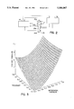
- FIG. 7 is a graph showing comfort pressures of a bladder or pressure chamber in an athletic shoe as a function of frequency and differential pressure as computed via a Fourier Transform.
- a support device or system for a human being, with automatic pressure or contour control comprises a superstructure, frame, or housing 12 defining a support surface 14 positionable in contact with a body part of a person (not shown).
- Measurement componentry 16 is provided on superstructure 12 for periodically measuring a predetermined biomechanical parameter, e.g., physical stress, of the person's body part to determine a load distribution on the body part.
- Form control componentry 18 is disposed on superstructure 12 and is operatively connected to measurement componentry 16 for automatically subjecting support surface 14, in response to the determined load distribution, to forces tending to modify a contour or shape of support surface 14.
- Measurement componentry 16 includes or is connected to a fluid filled reservoir or chamber 20 which is at support surface 14. At least that portion of chamber 20 defined by or adjacent to support surface 14 is partially flexible to enable a modification of the contour or shape of support surface 14.
- Measurement componentry 16 further includes a pressure detector 22 in operative engagement with fluid in pressure chamber 20 for monitoring changes in the pressure of the fluid, due, for example, to varying loads caused by physical activity of the user or wearer of the support device. In the case of a shoe (FIG. 2), a therapeutic brace (FIG. 4), or a piece of protective athletic padding (not shown), the changing physical activity of the user results in different load distributions over time.
- measurement componentry 16 includes pressure monitoring circuitry 24 operatively coupled to pressure detector 22 for characterizing changes in pressure of the fluid in pressure chamber 20 over time.
- Pressure monitoring circuitry 24 includes a sampling circuit 26 operatively coupled to detector 22 for periodically sampling the fluid pressure in chamber 20, as sensed by detector 22.
- Sampling circuit 26 is electrically tied to a buffer memory 28 which stores a predetermined number of successive pressure values.
- Pressure monitoring circuitry 24 further includes a subcircuit 30 linked at an output to buffer memory 28 for deriving measured differential pressure as a function of time.
- a second subcircuit 32 of pressure monitoring circuitry 24 operatively connected at an output to subcircuit 30 functions to compute a Fourier Transform on the pressure function determined by subcircuit 30, converting pressure function of time to a spectral (frequency) function.
- Subcircuit 32 functions in conjunction with another subcircuit 33 of pressure monitoring circuitry 24 operatively tied at an output to subcircuit 30.
- Subcircuit 33 operates to determine differential pressures associated with spectral frequencies computed by subcircuit 32.
- Another subcircuit 34 of pressure monitoring circuitry 24 is a memory which stores a table of optimal comfort pressures as a function of frequency and differential pressure.
- Subcircuit 34 is accessed by a pressure value selection subcircuit 36 which is operatively connected to Fourier computation subcircuit 32 and determination subcircuit 33 for receiving calculated frequency and pressure data therefrom.
- subcircuit 36 selects a "comfort pressure" from the table of such values stored in memory 34.
- the comfort pressures stored in memory subcircuit 34 represent optimal pressures for the fluid in chamber 20, i.e., pressures which maximize comfort and support for the wearer, depending on the type and intensity of physical activity and accordingly on the load distribution experienced by the body part in contact with support superstructure 12.
- the optimal pressure (the comfort pressure selected from memory 34) is impettid in pressure chamber 20 by form control componentry 18.
- Componentry 18 includes a pressure control circuit 38 connected at an output to pressure value selector subcircuit 36 and at an input to a pressure source or pressurization element 40 such as a pump.
- Pressure source 40 is connected to pressure chamber via a valve 42 which is responsive to pressure control 38.
- Valve 42 which is part of form control componentry 18, is controlled to release pressure fluid from chamber 20 or to admit more fluid into that chamber from pressure source 40, in accordance with control signals from pressure control 38.
- the comfort pressures stored in memory subcircuit 34 are determined empirically. A series of test individuals are subjected to each of a plurality of different load distributions over time and to a plurality of different test pressures at the respective support surface for each load distribution. The subjects are asked to select which test pressure is most comfortable. A statistical mean, median or mode is computed from the selected test pressures. That mean, median or mode is designated the comfort pressure for the respective load distribution.
- subcircuit 36 may compute a comfort pressure from the calculated frequency and pressure data from subcircuits 32 and 33 by utilizing a multiple regression equation whose coefficients are empirically determined and stored, e.g., in memory subcircuit 34. The exact values of the coefficients will vary depending on the number of test subjects and their responses.
- FIG. 7 is a graph showing comfort pressures P C of a bladder or pressure chamber in an athletic shoe as a function of frequency F and differential pressure P D as computed via a Fourier Transform.
- the graph of FIG. 7 is derived using the following multiple regression equation as a model:
- FIG. 2 schematically depicts a particular embodiment of the device of FIG. 1 where superstructure 12 takes the form of an athletic shoe 44.
- Support surface 14 may in that case take the form of an insole (not shown) of shoe 44.
- Pressure chamber 20 is one of a plurality of pressure chambers 20a, 20b, 20c, 20d disposed under different areas of the sole, namely, the toe, the balls, the instep, and the heel, respectively.
- Pressure chambers 20a, 20b, 20c, 20d are operatively connected to sampling circuit 26 of measurement componentry 16 via one or more pressure detectors 22 (not shown) and pressure source 40 of form control componentry 18 via valve 42.
- sampling circuit 26 sequentially samples the pressures of the different chambers 20a, 20b, 20c, 20d, while subcircuit 30 determines four different functions of pressure vs. time.
- Subcircuit 32 performs a Fourier Transform computation for each of the pressure functions, while subcircuit 36 selects four comfort pressures based on the results of the Fourier Transform.
- valve 42 and pressure source 40 function to institute the selected comfort pressures in the respective chambers 20a, 20b, 20c, 20d of shoe 44.
- measurement componentry 16 effectively determines the frequency and magnitude of impacts on the user's foot.
- form control componentry 18 modifies the base pressures in chambers 20a, 20b, 20c, 20d to optimize comfort for the user.
- the pressures applied to the fluid in chambers 20a, 20b, 20c, 20d where the user jumps frequently as in basketball or volleyball will be different from the pressures applied to the fluid in chambers 20a, 20b, 20c, 20d where the user has a lesser, more constant impact on the foot as in field and track activities.
- pressure monitoring circuitry 24 can detect a change in tactics from a consistent base line volleying to a frequent rush to the net and induce form control componentry 18 to modify the pressure in chambers 20a, 20b, 20c, 20d accordingly. This capability arises from the monitoring of pressure changes over time and the automatic analysis of those pressure changes to provide an optimal comfort pressure.
- a single pressure detector 22 may be connected via valving (not shown) to the different pressure chambers 20a, 20b, 20c, 20d.
- multiple pressure detectors may be provided.
- pressure detector 22 may be operative to sample sequential pressures from only one chamber 20a, 20b, 20c, or 20d which is then used as the standard by which the comfort pressures of the other chambers are set. It is to be noted that, for a shoe or other similar pressurizable support, the "comfort pressure" becomes a minimum or base pressure relative to which changes of ditterentail pressures are indicative of load or stress on the foot or other body part which is in contact with the support.
- support surface 14 may be substantially the entire insole of an shoe, a side panel, an upper, or in the case of a high topped shoe, an ankle portion.
- FIG. 3 is a graph illustrating, by way of example, a mathematical comfort surface. With an arbitray scale, the z-axis represents an emirically determined comfort pressure as a function of an impact frequency and magnitude as determined via Fourier Transforms. The information represented by the graph of FIG. 3 is encoded in tabular form and stored in memory 34.
- selection subcircuit 36 may operate to select a comfort pressure based on a categorization of the results.
- categories may be predefined, for example, in accordance with the particular applications intended for the support.
- relevant classifications may include (a) low impact, high frequency impacts, (b) high impact, low frequency, (c) high impact, high frequency, and (d) low impact, low frequency.
- selector subcircuit 36 accesses memory 34 to determine optimal pressurization.
- support superstructure 12 (FIG. 1) is a protective athletic device such as a shoe 44 (FIG. 2), a knee brace 46 (FIG. 4), or a shoulder pad (not shown)
- measurement componentry 16 advantageously functions to monitor frequency and intensity of impacts.
- the effect of therapeutic braces is also improved or optimized where measurement componentry 16 is provided for monitoring frequency and intensity of impacts on the braced body part.
- the degree of pressure applied to knee or leg brace 46 (FIG. 4) and thus the tightness of the fit of the brace to the knee or leg, can be reduced where the individual is resting or walking slowly, to permit slow strengthening of the leg muscles.
- the degree of pressure applied to a knee or leg via pressure chambers 48a, 48b, 48c, 48d in brace 46, and thus the tightness of the fit of the brace to the knee or leg, can be increased to provide greater support. It is also possible to program form control componentry 18 so that the degree of support provided varies over time. As healing progresses, less support is applied even in stressful activities such as running or jumping.
- FIG. 5 depicts a bed 50 provided with a plurality of relatively small pressurizable chambers 52 disposed in a rectangular array. Chambers 52 are operatively connected to pressure sampling circuit 26 of measurement componentry 16 via one pressure detector or, alternatively, respective detectors and to pressure source 40 of form control componentry 18 via valving (not shown). In the case of bed 50, it is in many instances not so important to measure changes over time, but to determine whether a change in posture has occurred and to determine the new posture for purposes of modifying the pressurization of chambers 52 to maximize comfort.
- the inputs from pressure chambers 52 are monitored to detect any change in loading.
- the differential pressures are compared to pre-established load distributions which have been stored in an internal memory. This comparison results in a determination of the new loading, i.e., the new posture assumed by the person on the bed.
- a memory of comfort pressure distributions is consulted to ascertain a most comfortable pressure distribution, as determined empirically.
- Pressure source 40 and its associated valving is then actuated to implement the optimal load distribution.
- form control componentry 18 actually modifies a contour of support surface 14 of bed 50.
- Surface 14 conforms at least partially to the profile of the user in contact with the bed.
- the bed changes contour to insert a hump into the hollow of the lower back and to slightly prop up the head.
- form control componentry 18 modifies the contour of the bed surface to slightly reduce the elevation of the head and to receive a protruding belly or lower abdomen, thereby relieving possible stress on the lower back.
- FIG. 6 shows support surface 14 as a back 54 of a chair 56.
- pressure monitoring circuitry 24 of measurement componentry 16 monitors, in part, biomechanical stress on the user's back as sensed via pressure chambers 58.
- the base pressures of an array of pressure chambers are controlled to stimulate desirable motion of the user.
- a bed or chair may be controlled so as to induce desirable movement of the user.
- a person may be induced, through intelligent control componentry, to move through a prescribed series of positions empirically determined to optimize comfort, relaxation and sleep.
- measurement componentry 16 in periodically and automatically measuring physical stress of a body part in contact with support surface 14 and in automatically analyzing physical stress to obtain a distribution of the measured stress, provides useful information to biomechanical investigators researching the reactions of human tissue and organs to differing kinds and levels of physical loading.
- pressure or contour control at the contact surface may be implemented in at least some applications by means other than hydraulic or pneumatic. Multiple electric motors operating respective rack and pinion mechanisms may accomplish surface control.
- biomechanical parameters may be measured to determine loading of a body part. For instance, local galvanic skin response as an indicator of muscle exertion.
Abstract
Description
P.sub.C =-0.57×(P.sub.D).sup.2 +3.22×P.sub.D +1.18×F.
Claims (29)
Priority Applications (5)
| Application Number | Priority Date | Filing Date | Title |
|---|---|---|---|
| US08/277,230 US5586067A (en) | 1994-07-19 | 1994-07-19 | Support enhancing device and associated method |
| US08/340,541 US5587933A (en) | 1994-07-19 | 1994-11-16 | Support enhancing device and associated method |
| EP95927343A EP0772838A4 (en) | 1994-07-19 | 1995-07-19 | Support enhancing device and associated method |
| PCT/US1995/009233 WO1996002181A2 (en) | 1994-07-19 | 1995-07-19 | Support enhancing device and associated method |
| AU31398/95A AU3139895A (en) | 1994-07-19 | 1995-07-19 | Support enhancing device and associated method |
Applications Claiming Priority (1)
| Application Number | Priority Date | Filing Date | Title |
|---|---|---|---|
| US08/277,230 US5586067A (en) | 1994-07-19 | 1994-07-19 | Support enhancing device and associated method |
Related Child Applications (1)
| Application Number | Title | Priority Date | Filing Date |
|---|---|---|---|
| US08/340,541 Continuation-In-Part US5587933A (en) | 1994-07-19 | 1994-11-16 | Support enhancing device and associated method |
Publications (1)
| Publication Number | Publication Date |
|---|---|
| US5586067A true US5586067A (en) | 1996-12-17 |
Family
ID=23059950
Family Applications (1)
| Application Number | Title | Priority Date | Filing Date |
|---|---|---|---|
| US08/277,230 Expired - Fee Related US5586067A (en) | 1994-07-19 | 1994-07-19 | Support enhancing device and associated method |
Country Status (1)
| Country | Link |
|---|---|
| US (1) | US5586067A (en) |
Cited By (32)
| Publication number | Priority date | Publication date | Assignee | Title |
|---|---|---|---|---|
| WO1998007342A1 (en) * | 1996-08-19 | 1998-02-26 | Professional Footcare International, Inc. | Method of making injection molded orthotics |
| US6230501B1 (en) | 1994-04-14 | 2001-05-15 | Promxd Technology, Inc. | Ergonomic systems and methods providing intelligent adaptive surfaces and temperature control |
| US6418394B1 (en) * | 1997-05-21 | 2002-07-09 | Polar Electro Oy | Measuring device and method of controlling same |
| US6540707B1 (en) * | 1997-03-24 | 2003-04-01 | Izex Technologies, Inc. | Orthoses |
| US20050043660A1 (en) * | 2003-03-31 | 2005-02-24 | Izex Technologies, Inc. | Orthoses |
| US7107706B1 (en) * | 1997-08-14 | 2006-09-19 | Promdx Technology, Inc. | Ergonomic systems and methods providing intelligent adaptive surfaces and temperature control |
| US7204041B1 (en) * | 1997-08-14 | 2007-04-17 | Promdx Technology, Inc. | Ergonomic systems and methods providing intelligent adaptive surfaces |
| US20070163147A1 (en) * | 2005-09-21 | 2007-07-19 | Cavanagh Peter R | Method for Design and Manufacture of Insoles |
| US20080083416A1 (en) * | 2006-09-21 | 2008-04-10 | Bin Xia | Footcare product dispensing kiosk |
| US20080282580A1 (en) * | 2004-07-10 | 2008-11-20 | Kim Ji-Woog | Method and Apparatus for Curing Body Status |
| US20100018327A1 (en) * | 2005-06-21 | 2010-01-28 | Aisin Seiki Kabushiki Kaisha | Load detecting apparatus and load detecting method |
| ITPI20080073A1 (en) * | 2008-08-07 | 2010-02-08 | Salvatore Raino | ORTHOPEDIC SUPPORT STRUCTURE |
| US8308794B2 (en) | 2004-11-15 | 2012-11-13 | IZEK Technologies, Inc. | Instrumented implantable stents, vascular grafts and other medical devices |
| US8491572B2 (en) | 2004-11-15 | 2013-07-23 | Izex Technologies, Inc. | Instrumented orthopedic and other medical implants |
| US8678979B2 (en) | 1998-09-01 | 2014-03-25 | Izex Technologies, Inc. | Remote monitoring of a patient |
| US20140165427A1 (en) * | 2012-12-17 | 2014-06-19 | Nike, Inc. | Electronically Controlled Bladder Assembly |
| US8790258B2 (en) | 1999-06-23 | 2014-07-29 | Izex Technologies, Inc. | Remote psychological evaluation |
| US20150000157A1 (en) * | 2013-07-01 | 2015-01-01 | M-Support Limited Company | Manufacturing method of insole and insole manufactured by the method |
| US9038482B2 (en) | 2006-09-21 | 2015-05-26 | Msd Consumer Care, Inc. | Footcare product dispensing kiosk |
| CN105407855A (en) * | 2013-06-04 | 2016-03-16 | 西格玛仪器控股有限责任公司 | Diagnostic and therapeutic treatment device, and related systems and methods of utilizing such a device |
| CN105533907A (en) * | 2016-02-24 | 2016-05-04 | 京东方科技集团股份有限公司 | Health care shoe |
| US9782324B2 (en) | 2011-09-15 | 2017-10-10 | Sigma Instruments Holdings, Llc | System and method for treating skin and underlying tissues for improved health, function and/or appearance |
| US9861547B2 (en) | 2011-09-15 | 2018-01-09 | Sigma Instruments Holdings, Llc | Systems and methods for preventing, managing and/or treating peripheral neuropathy, peripheral vascular disease, erectile dysfunction, urinary incontinence, cellulite and other conditions |
| US10226397B2 (en) | 2011-09-15 | 2019-03-12 | Sigma Instruments Holdings, Llc | System and method for treating soft tissue with force impulse and electrical stimulation |
| US10232172B1 (en) * | 2015-08-25 | 2019-03-19 | Neurological Fitness Equipment and Education LLC | System and methods to track and increase muscle efficiency |
| US10342649B2 (en) | 2011-09-15 | 2019-07-09 | Sigma Instruments Holdings, Llc | System and method for treating animals |
| US20210093049A1 (en) * | 2018-03-20 | 2021-04-01 | Molibso Entwicklungs- Und Vertriebs Gmbh | Method, device and system for measuring, evaluating and simulating a shoe |
| US11020188B2 (en) | 2017-11-10 | 2021-06-01 | Sigma Instruments Holdings, Llc | System, method, and GUI for treating skin and underlying tissues for improved health, function and/or appearance |
| US11041737B2 (en) * | 2014-09-30 | 2021-06-22 | SZ DJI Technology Co., Ltd. | Method, device and system for processing a flight task |
| US11089448B2 (en) * | 2006-04-21 | 2021-08-10 | Refinitiv Us Organization Llc | Systems and methods for the identification and messaging of trading parties |
| US11134863B2 (en) | 2015-10-05 | 2021-10-05 | Scholl's Wellness Company Llc | Generating orthotic product recommendations |
| US11854058B2 (en) | 2017-10-13 | 2023-12-26 | Scholl's Wellness Company Llc | Footcare product dispensing kiosk |
Citations (4)
| Publication number | Priority date | Publication date | Assignee | Title |
|---|---|---|---|---|
| US5060174A (en) * | 1990-04-18 | 1991-10-22 | Biomechanics Corporation Of America | Method and apparatus for evaluating a load bearing surface such as a seat |
| US5170364A (en) * | 1990-12-06 | 1992-12-08 | Biomechanics Corporation Of America | Feedback system for load bearing surface |
| US5176424A (en) * | 1988-06-10 | 1993-01-05 | Mazda Motor Corporation | Automobile seat assembly |
| US5230249A (en) * | 1990-08-20 | 1993-07-27 | Casio Computer Co., Ltd. | Shoe or boot provided with tank chambers |
-
1994
- 1994-07-19 US US08/277,230 patent/US5586067A/en not_active Expired - Fee Related
Patent Citations (5)
| Publication number | Priority date | Publication date | Assignee | Title |
|---|---|---|---|---|
| US5176424A (en) * | 1988-06-10 | 1993-01-05 | Mazda Motor Corporation | Automobile seat assembly |
| US5060174A (en) * | 1990-04-18 | 1991-10-22 | Biomechanics Corporation Of America | Method and apparatus for evaluating a load bearing surface such as a seat |
| US5230249A (en) * | 1990-08-20 | 1993-07-27 | Casio Computer Co., Ltd. | Shoe or boot provided with tank chambers |
| US5170364A (en) * | 1990-12-06 | 1992-12-08 | Biomechanics Corporation Of America | Feedback system for load bearing surface |
| US5283735A (en) * | 1990-12-06 | 1994-02-01 | Biomechanics Corporation Of America | Feedback system for load bearing surface |
Cited By (51)
| Publication number | Priority date | Publication date | Assignee | Title |
|---|---|---|---|---|
| US6865825B2 (en) * | 1994-04-14 | 2005-03-15 | Promdx Technology, Inc. | Ergonomic systems and methods providing intelligent adaptive surfaces and temperature control |
| US6230501B1 (en) | 1994-04-14 | 2001-05-15 | Promxd Technology, Inc. | Ergonomic systems and methods providing intelligent adaptive surfaces and temperature control |
| US5746952A (en) * | 1996-08-19 | 1998-05-05 | Professional Footcare International, Inc. | Method of making injection molded orthotics |
| US6042759A (en) * | 1996-08-19 | 2000-03-28 | Marshall; Scott | Method of making molded orthotics |
| WO1998007342A1 (en) * | 1996-08-19 | 1998-02-26 | Professional Footcare International, Inc. | Method of making injection molded orthotics |
| US6540707B1 (en) * | 1997-03-24 | 2003-04-01 | Izex Technologies, Inc. | Orthoses |
| US6418394B1 (en) * | 1997-05-21 | 2002-07-09 | Polar Electro Oy | Measuring device and method of controlling same |
| US7204041B1 (en) * | 1997-08-14 | 2007-04-17 | Promdx Technology, Inc. | Ergonomic systems and methods providing intelligent adaptive surfaces |
| US7107706B1 (en) * | 1997-08-14 | 2006-09-19 | Promdx Technology, Inc. | Ergonomic systems and methods providing intelligent adaptive surfaces and temperature control |
| US7395614B1 (en) * | 1997-08-14 | 2008-07-08 | Promdx Technology, Inc. | Intelligent footwear |
| US8678979B2 (en) | 1998-09-01 | 2014-03-25 | Izex Technologies, Inc. | Remote monitoring of a patient |
| US9230057B2 (en) | 1998-09-01 | 2016-01-05 | Izex Technologies, Inc. | Remote monitoring of a patient |
| US8790258B2 (en) | 1999-06-23 | 2014-07-29 | Izex Technologies, Inc. | Remote psychological evaluation |
| US20050043660A1 (en) * | 2003-03-31 | 2005-02-24 | Izex Technologies, Inc. | Orthoses |
| US20080282580A1 (en) * | 2004-07-10 | 2008-11-20 | Kim Ji-Woog | Method and Apparatus for Curing Body Status |
| US8784475B2 (en) | 2004-11-15 | 2014-07-22 | Izex Technologies, Inc. | Instrumented implantable stents, vascular grafts and other medical devices |
| US8308794B2 (en) | 2004-11-15 | 2012-11-13 | IZEK Technologies, Inc. | Instrumented implantable stents, vascular grafts and other medical devices |
| US8491572B2 (en) | 2004-11-15 | 2013-07-23 | Izex Technologies, Inc. | Instrumented orthopedic and other medical implants |
| US8740879B2 (en) | 2004-11-15 | 2014-06-03 | Izex Technologies, Inc. | Instrumented orthopedic and other medical implants |
| US20100018327A1 (en) * | 2005-06-21 | 2010-01-28 | Aisin Seiki Kabushiki Kaisha | Load detecting apparatus and load detecting method |
| US7900523B2 (en) * | 2005-06-21 | 2011-03-08 | Aisin Seiki Kabushiki Kaisha | Load detecting apparatus and load detecting method |
| US20070163147A1 (en) * | 2005-09-21 | 2007-07-19 | Cavanagh Peter R | Method for Design and Manufacture of Insoles |
| US11089448B2 (en) * | 2006-04-21 | 2021-08-10 | Refinitiv Us Organization Llc | Systems and methods for the identification and messaging of trading parties |
| US9576311B2 (en) | 2006-09-21 | 2017-02-21 | Bayer Healthcare Llc | Footcare product dispensing kiosk |
| US20080083416A1 (en) * | 2006-09-21 | 2008-04-10 | Bin Xia | Footcare product dispensing kiosk |
| US9038482B2 (en) | 2006-09-21 | 2015-05-26 | Msd Consumer Care, Inc. | Footcare product dispensing kiosk |
| US8117922B2 (en) * | 2006-09-21 | 2012-02-21 | Msd Consumer Care, Inc. | Footcare product dispensing kiosk |
| ITPI20080073A1 (en) * | 2008-08-07 | 2010-02-08 | Salvatore Raino | ORTHOPEDIC SUPPORT STRUCTURE |
| WO2011015894A1 (en) * | 2008-08-07 | 2011-02-10 | Raino Salvatore | Orthopaedic support structure |
| US9782324B2 (en) | 2011-09-15 | 2017-10-10 | Sigma Instruments Holdings, Llc | System and method for treating skin and underlying tissues for improved health, function and/or appearance |
| US10342649B2 (en) | 2011-09-15 | 2019-07-09 | Sigma Instruments Holdings, Llc | System and method for treating animals |
| US10226397B2 (en) | 2011-09-15 | 2019-03-12 | Sigma Instruments Holdings, Llc | System and method for treating soft tissue with force impulse and electrical stimulation |
| US9861547B2 (en) | 2011-09-15 | 2018-01-09 | Sigma Instruments Holdings, Llc | Systems and methods for preventing, managing and/or treating peripheral neuropathy, peripheral vascular disease, erectile dysfunction, urinary incontinence, cellulite and other conditions |
| US9066558B2 (en) * | 2012-12-17 | 2015-06-30 | Nike, Inc. | Electronically controlled bladder assembly |
| US9655402B2 (en) | 2012-12-17 | 2017-05-23 | Nike, Inc. | Electronically controlled bladder assembly |
| US11185126B2 (en) | 2012-12-17 | 2021-11-30 | Nike, Inc. | Electronically controlled bladder assembly |
| US10098413B2 (en) | 2012-12-17 | 2018-10-16 | Nike, Inc. | Electronically controlled bladder assembly |
| US20140165427A1 (en) * | 2012-12-17 | 2014-06-19 | Nike, Inc. | Electronically Controlled Bladder Assembly |
| US10575589B2 (en) | 2012-12-17 | 2020-03-03 | Nike, Inc. | Electronically controlled bladder assembly |
| US11793272B2 (en) | 2012-12-17 | 2023-10-24 | Nike, Inc. | Electronically controlled bladder assembly |
| CN105407855A (en) * | 2013-06-04 | 2016-03-16 | 西格玛仪器控股有限责任公司 | Diagnostic and therapeutic treatment device, and related systems and methods of utilizing such a device |
| US20150000157A1 (en) * | 2013-07-01 | 2015-01-01 | M-Support Limited Company | Manufacturing method of insole and insole manufactured by the method |
| US11041737B2 (en) * | 2014-09-30 | 2021-06-22 | SZ DJI Technology Co., Ltd. | Method, device and system for processing a flight task |
| US11566915B2 (en) | 2014-09-30 | 2023-01-31 | SZ DJI Technology Co., Ltd. | Method, device and system for processing a flight task |
| US10232172B1 (en) * | 2015-08-25 | 2019-03-19 | Neurological Fitness Equipment and Education LLC | System and methods to track and increase muscle efficiency |
| US11179563B2 (en) | 2015-08-25 | 2021-11-23 | Neurological Fitness Equipment and Education LLC | System and methods to track and increase muscle efficiency |
| US11134863B2 (en) | 2015-10-05 | 2021-10-05 | Scholl's Wellness Company Llc | Generating orthotic product recommendations |
| CN105533907A (en) * | 2016-02-24 | 2016-05-04 | 京东方科技集团股份有限公司 | Health care shoe |
| US11854058B2 (en) | 2017-10-13 | 2023-12-26 | Scholl's Wellness Company Llc | Footcare product dispensing kiosk |
| US11020188B2 (en) | 2017-11-10 | 2021-06-01 | Sigma Instruments Holdings, Llc | System, method, and GUI for treating skin and underlying tissues for improved health, function and/or appearance |
| US20210093049A1 (en) * | 2018-03-20 | 2021-04-01 | Molibso Entwicklungs- Und Vertriebs Gmbh | Method, device and system for measuring, evaluating and simulating a shoe |
Similar Documents
| Publication | Publication Date | Title |
|---|---|---|
| US5586067A (en) | Support enhancing device and associated method | |
| US5587933A (en) | Support enhancing device and associated method | |
| Norris et al. | Hip-and thigh-muscle activation during the star excursion balance test | |
| Mille et al. | Thresholds for inducing protective stepping responses to external perturbations of human standing | |
| Horak et al. | Diabetic neuropathy and surface sway-referencing disrupt somatosensory information for postural stability in stance | |
| Carpenter et al. | Surface height effects on postural control: a hypothesis for a stiffness strategy for stance | |
| Bot et al. | The relationship between heart rate and oxygen uptake during non-steady state exercise | |
| Van Hedel et al. | The influence of age on learning a locomotor task | |
| Filippi et al. | Improvement of stance control and muscle performance induced by focal muscle vibration in young-elderly women: a randomized controlled trial | |
| Coupé et al. | Low-magnitude whole body vibration with resistive exercise as a countermeasure against cardiovascular deconditioning after 60 days of head-down bed rest | |
| Ghezelbash et al. | Trunk musculoskeletal response in maximum voluntary exertions: A combined measurement-modeling investigation | |
| Petrofsky et al. | Autonomic stress and balance—the impact of age and diabetes | |
| Guzii et al. | Post-loading dynamics of beat-to-beat blood pressure variability in highly trained athletes during sympathetic and parasympathetic overstrain formation | |
| Boutcher et al. | Cardiovascular responses to light isometric and aerobic exercise in 21-and 59-year-old males | |
| Russell et al. | Variation in lumbar spine mobility measured over a 24-hour period | |
| Kim et al. | Testing the assumption of normality in body sway area calculations during unipedal stance tests with an inertial sensor | |
| Hosoi et al. | A new method for the assessment of venous insufficiency in primary varicose veins using near-infrared spectroscopy | |
| Hosoda et al. | The effects of footwear on standing posture control | |
| Namkoong et al. | Effects of different sitting positions on skin temperature of the lower extremity | |
| Prajapat et al. | Cardiac autonomic profile of soccer, field hockey and basketball players: a comparative study | |
| JP4686308B2 (en) | Lower limb training device | |
| JP2003275317A (en) | Massaging machine | |
| Tyson et al. | The measurement of balance and walking post-stroke. Part 2: Functional performance tests | |
| KR101918854B1 (en) | Health machine control system that reflects stress and bio index | |
| Demura et al. | Effect of Japanese sitting style (seiza) on the center of foot pressure after standing |
Legal Events
| Date | Code | Title | Description |
|---|---|---|---|
| AS | Assignment |
Owner name: BIOMECHANICS CORPORATION OF AMERICA, NEW YORK Free format text: ASSIGNMENT OF ASSIGNORS INTEREST;ASSIGNORS:GROSS, CLIFFORD M.;BO, LIN;LU, HONZHENG;REEL/FRAME:007087/0274 Effective date: 19940714 |
|
| AS | Assignment |
Owner name: BCAM INTERNATIONAL, INC., NEW YORK Free format text: CHANGE OF NAME;ASSIGNOR:BIOMECHANICS CORPORATION OF AMERICA;REEL/FRAME:008116/0765 Effective date: 19950622 |
|
| FEPP | Fee payment procedure |
Free format text: PAYOR NUMBER ASSIGNED (ORIGINAL EVENT CODE: ASPN); ENTITY STATUS OF PATENT OWNER: SMALL ENTITY |
|
| REFU | Refund |
Free format text: REFUND - PAYMENT OF MAINTENANCE FEE, 4TH YR, SMALL ENTITY (ORIGINAL EVENT CODE: R283); ENTITY STATUS OF PATENT OWNER: SMALL ENTITY |
|
| FPAY | Fee payment |
Year of fee payment: 4 |
|
| FPAY | Fee payment |
Year of fee payment: 8 |
|
| SULP | Surcharge for late payment |
Year of fee payment: 7 |
|
| FEPP | Fee payment procedure |
Free format text: PAYER NUMBER DE-ASSIGNED (ORIGINAL EVENT CODE: RMPN); ENTITY STATUS OF PATENT OWNER: SMALL ENTITY Free format text: PAYOR NUMBER ASSIGNED (ORIGINAL EVENT CODE: ASPN); ENTITY STATUS OF PATENT OWNER: SMALL ENTITY |
|
| REMI | Maintenance fee reminder mailed | ||
| LAPS | Lapse for failure to pay maintenance fees | ||
| STCH | Information on status: patent discontinuation |
Free format text: PATENT EXPIRED DUE TO NONPAYMENT OF MAINTENANCE FEES UNDER 37 CFR 1.362 |
|
| FP | Lapsed due to failure to pay maintenance fee |
Effective date: 20081217 |