US5588033A - Method and apparatus for three dimensional image reconstruction from multiple stereotactic or isocentric backprojections - Google Patents
Method and apparatus for three dimensional image reconstruction from multiple stereotactic or isocentric backprojections Download PDFInfo
- Publication number
- US5588033A US5588033A US08/466,829 US46682995A US5588033A US 5588033 A US5588033 A US 5588033A US 46682995 A US46682995 A US 46682995A US 5588033 A US5588033 A US 5588033A
- Authority
- US
- United States
- Prior art keywords
- image
- dimensional
- images
- voxels
- intersected
- Prior art date
- Legal status (The legal status is an assumption and is not a legal conclusion. Google has not performed a legal analysis and makes no representation as to the accuracy of the status listed.)
- Expired - Fee Related
Links
Images


Classifications
-
- G—PHYSICS
- G06—COMPUTING; CALCULATING OR COUNTING
- G06T—IMAGE DATA PROCESSING OR GENERATION, IN GENERAL
- G06T11/00—2D [Two Dimensional] image generation
- G06T11/003—Reconstruction from projections, e.g. tomography
- G06T11/006—Inverse problem, transformation from projection-space into object-space, e.g. transform methods, back-projection, algebraic methods
-
- Y—GENERAL TAGGING OF NEW TECHNOLOGICAL DEVELOPMENTS; GENERAL TAGGING OF CROSS-SECTIONAL TECHNOLOGIES SPANNING OVER SEVERAL SECTIONS OF THE IPC; TECHNICAL SUBJECTS COVERED BY FORMER USPC CROSS-REFERENCE ART COLLECTIONS [XRACs] AND DIGESTS
- Y10—TECHNICAL SUBJECTS COVERED BY FORMER USPC
- Y10S—TECHNICAL SUBJECTS COVERED BY FORMER USPC CROSS-REFERENCE ART COLLECTIONS [XRACs] AND DIGESTS
- Y10S378/00—X-ray or gamma ray systems or devices
- Y10S378/901—Computer tomography program or processor
Definitions
- the present invention relates to a method and apparatus for three dimensional image reconstruction.
- the present invention relates to a method and apparatus for reconstructing a three dimensional image of anatomical structures or regions of interest within a patient's body using stereotactic or isocentric backprojections.
- CT Computed Tomography
- An algorithm based on the Fourier theorem is used in CT imaging to reconstruct the three dimensional anatomical structures as a sequence of two dimensional image slices.
- Stereotactic radiography has long been established as the imaging modality for the precise localization and radiosurgical treatment of point targets within a patient's body.
- One example, in which stereotactic radiography is useful is the application of stereotactic angiography in the diagnosis and treatment of arteriovenous malformations (AVM) in the brain.
- AVM arteriovenous malformations
- the present known angiography technique fails to provide a mechanism for accurate determination of the three dimensional shape or volume of the AVM. This deficiency leads to an overestimation of the size of the AVM, leading to radiation treatment of healthy brain tissue.
- CT angiography may often highlight the AVM, but it cannot clearly differentiate the feeding and draining vessels and the nidus containing the abnormal vascular shunts. It is critical to differentiate these components of the AVM for proper treatment.
- MRA Magnetic Reliable and Low Resolution
- Conventional angiography despite its limitations, provides temporal and spatial resolution of the AVM superior to that of CT and MR angiography. In fact, it is the only technique capable of resolving components of the AVM, such as the feeding artery, nidus and draining vein.
- the present invention is a new method which takes advantage of the precision of stereotactic angiography, and provides accurate three dimensional reconstruction of the AVM. Additionally, the present invention can be used in many other clinical applications to faithfully reconstruct an image of a region of interest within a patient's body.
- the present invention presents a three dimensional reconstruction technique using backprojections of multiple, two dimensional projection images.
- the invention may be applied to a variety of clinical applications.
- the present method for three dimensional reconstruction of an object from a stereotactic or isocentric backprojection includes the step of performing radiography of the object to produce a two dimensional image of the object on film or a digital image if digital radiography is used. The two dimensional image is then backprojected through a reconstruction volume.
- the process of backprojection consists of determining the position of the point source and the image plane of the radiograph relative to the reconstruction volume.
- the target area on the radiograph is then determined.
- Each pixel within the target area is backprojected through the reconstruction volume to its point source.
- the line formed between each pixel and the point source is referred to as a rayline.
- the reconstruction volume is divided into cubic units called voxels.
- Each rayline, as it is formed during backprojection, intersects several of the voxels in the reconstruction volume. The combination of all of the intersected voxels for a particular view defines the a three dimensional image of the object for that view.
- Radiographs are taken of the object from several different view angles.
- the process of backprojection is repeated for each view of the object to produce a three dimensional, reconstructed image of the object for each view. All of the three dimensional reconstructed images are then superimposed on each other, and values associated with their voxels are summed. After superimposing the images, those voxels found in all of the three dimensional reconstructed images define the final, three dimensional reconstructed volume image of the object.
- the stereotactic localizer frame includes eight X-ray transparent, rigid plates which are securely fastened to a base and top portion of the frame. One face of each plate has four radiopaque fiducial marks disposed on it. These fiducial marks are used during the process of reconstruction to determine the position of the point source and the image plane relative to the reconstruction volume.
- the present stereotactic localizer frame provides a wider range of viewing angles than a conventional localizer frame.
- two dimensional images of the object may be obtained from more view angles, so that the actual three dimensional shape of the object can be reconstructed with greater accuracy than with a conventional localizer frame.
- This method can be used in a variety of clinical applications, including the treatment of AVM, three dimensional dosimetry in brachytherapy, the reconstruction of a cerebral arterial tree, and potentially any other clinical application in which reconstruction of a three dimensional image of anatomical structures or regions of interest within a patient's body is desired.
- FIG. 1 shows a perspective view of a conventional, stereotactic frame used in radiography.
- FIG. 2 shows a top view of the view angles available when using the frame of FIG. 1.
- FIG. 3 shows the relationship between a two dimensional image of the object and the three dimensional coordinate system employed in a conventional method for reconstruction of the target center of the object.
- FIG. 4 shows the relationship between a two dimensional image plane and a three dimensional reconstruction volume of the present invention in stereotactic localization.
- FIG. 5 shows a flow chart for the method of three dimensional reconstruction of the object from stereotactic backprojections.
- FIG. 6 shows a flow chart for the backprojecting step 504 of the method in FIG. 5.
- FIG. 7 shows a flow chart for the step 508 of determining the intersection of a reconstruction volume and raylines as shown in FIG. 5.
- FIG. 8 shows an apparatus used to perform the method of the invention as shown in FIGS. 5-7.
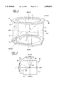
- FIG. 9 shows a perspective view of a stereotactic frame of the present invention.
- FIG. 10 shows a top view of the view angles available when using the frame of FIG. 9.
- FIGS. 11A-11F show six angiograms of an AVM taken during a clinical application of the present invention.
- FIGS. 12A and 12B show three dimensional reconstructed images of the AVM shown in FIG. 11.
- FIG. 13 shows a tree branch disposed within a stereotactic localizer frame of the present invention.
- FIG. 14 shows a radiograph taken from the anterior-posterior view of the tree branch shown in FIG. 13.
- FIG. 15 shows a radiograph taken from the lateral view of the tree branch shown in FIG. 13.
- FIG. 16 shows four binary images of the tree branch reproduced from the radiographic images taken of the tree branch shown in FIG. 13 from multiple view angles.
- FIG. 17 shows a three dimensional reconstructed image of the tree branch shown in FIG. 13 according to the present invention.
- FIG. 18 shows the relationship between a two dimensional image plane and a three dimensional reconstruction volume of the present invention in isocentric localization.
- Stereotactic radiography is a well established technique for precise localization of target points.
- One example of its conventional clinical application is in localization of arteriovenous malformations for radiosurgical treatment.
- FIG. 1 shows a perspective view of a conventional, stereotactic localizer frame 100 used in radiography.
- a stereotactic head frame such as a Brown, Roberts and Wells (BRW) or a Cosman, Roberts, and Wells (CRW) head ring (not shown)
- BCW Brown, Roberts and Wells
- CRW Cosman, Roberts, and Wells
- Stereotactic localizer frame 100 is then attached to the head frame.
- Stereotactic localizer frame 100 includes a rigid, X-ray transparent shell structure 102, typically made from a durable plastic.
- Shell 102 has a base portion 104 and a top portion 106 disposed parallel relative to each other.
- Base portion 104 is configured to be rigidly and securely fastened to the head ring.
- Conventional stereotactic localizer frame 100 has four faces 108, 110, 112, and 114. Faces 108 and 112 are parallel to each other and represent the anterior-posterior (AP) view. Faces 110 and 114 are parallel to each other and represent the left-right (LATERAL) view. Faces 108, 112 are preferably orthogonal to faces 110, 114.
- AP anterior-posterior
- LATERAL left-right
- Each face 108-114 contains a set 116, 118, 120, 122, respectively, of four fiducial marks.
- Sets 116-122 of fiducial marks are radiopaque so that they are visible on a radiograph. All four sets of fiducial marks are labeled so that they can be easily identified on the radiograph. For example, in FIG. 1 the fiducial marks of set 116 are labeled A, B, C, and D.
- stereotactic localizer frame 100 is securely attached to the head ring, a pair of radiographs are taken.
- a neuroradiologist chooses specific angulations and parameters for optimal visualization of the AVM.
- the view angles which can be used for imaging the AVM are limited because the two corresponding sets of fiducial marks 116, 120 or 118, 122 must appear in each radiograph.
- the film angulations are limited to the AP direction, having an axis 202, and the LATERAL direction, having an axis 204, or ⁇ 20 degrees off axes 202 and 204, so that all of the fiducial marks on opposing faces of stereotactic localizer frame 100 are captured on each radiograph.
- stereotactic localizer frame 100 has the disadvantage of creating a 50° gap 206 between available view angles on adjacent faces 108-112 as shown in FIG. 2. Gap 206 prevents radiographs from being taken over a large area of the AVM, thus making it difficult to accurately predict the three dimensional shape of the AVM. Without an accurate prediction of the shape of the AVM, the size of the AVM may be overestimated. As a result, healthy brain tissue may be unnecessarily treated with radiation.
- FIG. 3 shows example AP and LATERAL films 300 and 301 for the conventional stereotactic radiography procedure, each having a point source 310 and 312, respectively.
- Target areas 302 and 304 for radiation treatment are located on AP and LATERAL films 300 and 301, respectively.
- a geometric center 306 is determined for target area 302, and a geometric center 308 is determined for target area 304.
- Geometric centers 306 and 308 are projected back to their respective point sources 310 and 312. These backprojections create raylines 3 14 and 316 as shown in FIG. 3.
- raylines 314 and 316 can be mathematically reconstructed in three dimensional space. The intersection of these two raylines 314, 316 defines a target center 318 of the AVM.
- the two raylines will almost never intersect exactly due to finite accuracy, but the target center can generally still be located to an accuracy of ⁇ 0.3 mm.
- the superior-inferior extent, anterior-posterior extent and left-right extent of the AVM are determined from target areas 302 and 304.
- Sets of fiducial marks 116-122 (as shown in FIG. 3 projected onto films 300 and 301) and geometric centers 306, 308 are digitized and used to determine the spatial location of target center 318 relative to stereotactic localizer frame 100 (not shown in FIG. 3).
- the spatial location of target center 318 may be determined using the algorithm described in Siddon, R. L., et al., "Stereotaxic localization of intracranial targets," Int. J. Radiat. Oncol. Biol. Phys.
- Radiosurgical treatment is then delivered to target center 318 and to a spherical field 320 surrounding target center 318 having a diameter 322 estimated by the clinician to be large enough to cover the largest dimension of the target volume. This estimation is based on the target areas drawn on the AP and LATERAL films.
- This conventional treatment approach is unsatisfactory when the AVM is, for example, oblong in shape.
- the treatment delivery of a single, spherical dose volume needed to cover an oblong-shaped AVM will result in the unnecessary treatment of a larger amount of normal healthy brain tissue.
- One solution is to apply treatment to multiple target centers having smaller spherical fields and strategically placing target centers within the target volume for optimal coverage.
- this treatment requires knowledge of both the three dimensional shape and volume of the AVM.
- Conventional stereotactic angiography methods are not capable of producing such knowledge.
- MR angiography can provide information concerning the three dimensional shape and volume of the AVM, it cannot clearly show the critical components of the AVM necessary for effective treatment.
- FIG. 4 shows a method 400 for reconstructing a three dimensional target volume of the AVM for radiosurgical treatment for one view of the AVM, according to the present invention.
- Method 400 is based on three dimensional reconstruction from multiple stereotactic backprojections.
- two coordinate systems both cartesian, are defined.
- the first is a three dimensional coordinate system xyz defined relative to a head ring frame (not shown in FIG. 4).
- An example of the head ring frame is the BRW system where the coordinate axes are defined with respect to a patient's orientation, +X:Right, -X:Left, +Y:Anterior, -Y:Posterior, +Z:Superior, -Z:Inferior.
- a second, two dimensional coordinate system uv is defined with respect to an image plane 402.
- the reconstruction algorithm begins by taking a radiograph (not shown) of the AVM.
- the radiograph lies in image plane 402.
- the two dimensional coordinates of two sets of projected fiducial marks 404, 406 are digitized.
- An algorithm as described in the article by Siddon, R. L., et al., incorporated by reference herein earlier in this application, is used to determine both the source position S (x,y,z) (denoted by an "S" in FIG. 4) and the position of each of the projected fiducial marks in sets 404, 406.
- the projected fiducial marks from sets 404, 406 are used to define mathematically image plane 402 as follows.
- Projected fiducial marks from sets 404, 406 are also defined in two dimensional space as F" i (u,v).
- the unit vectors in the two dimensional image plane are U (1,0) and V (0,1).
- Any four projected fiducial marks from sets 404 and 406 are chosen, provided the resulting matrix equation described above is non-singular, to define the scalars A, B and C to solve the quadratic equation for U' and V'.
- eight projected fiducial marks 404, 406 two independent calculations can be made and the unit vectors U', V' are accurately determined by the normalized and mean values.
- a reconstruction volume 408 with desirable resolution is defined in three dimensional space.
- the resolution of reconstruction volume 408 depends on the specific clinical application for which the method is applied.
- Each unit of reconstruction volume 408 is referred to as a voxel 410 (i.e., a volumetric analog of a pixel).
- an image grid 412 with a desirable resolution is defined in two dimensional image plane 402.
- Each unit in image grid 412 is referred to as a pixel 414.
- the image of the AVM on the radiograph is digitized.
- P non zero pixel
- its two dimensional coordinates P(u p , v p ) are used to calculate its position P'(x p , y p , z p ) in three dimensional space
- O k is the kth component of O(x,y,z), the origin of the image plane.
- a rayline 422 a line that traces one of the non-zero pixels P in image plane 402 back to its point source S, is backprojected through reconstruction volume 408 to define intercepted voxels 424 in reconstruction volume 408.
- the resulting collection of intercepted voxels (not shown) is a three dimensional backprojected image (not shown) of the target area 416 of image plane 402.
- the above process is then repeated for all the other radiographs. All of the resulting reconstructed three dimensional images are then superimposed on each other, and the value of the voxels are summed.
- the sum of the values of the voxels within the final volume image equals four. Accordingly, the spatial boundary of the AVM in three dimensions is defined by the region corresponding to the intersection of all the backprojections.
- FIG. 5 shows a high level flow chart of the method 500 for three dimensional reconstruction of an image of an object from two dimensional images using backprojections.
- Step 502 illustrates the step of performing the radiography of the object from point source P to produce a two dimensional image, the radiograph, on image plane 402.
- Step 504 illustrates the step of backprojecting the two dimensional image through reconstruction volume 408 to point source P to produce a three dimensional reconstructed image.
- Step 506 illustrates the step of repeating the radiography and backprojecting steps for multiple views of the object. In the preferred embodiment, at least six views are used.
- Step 508 illustrates the step of determining an intersection volume in reconstruction volume 408 for all of the three dimensional reconstructed images. This intersection volume defines the final three dimensional, reconstructed volume image of the object.
- FIG. 6 provides a more detailed flow chart of backprojecting step 504.
- Backprojecting step 504 begins with a step 602 to determine the position of point source P relative to reconstruction volume 408. Step 604 then determines the position of image plane 402 relative to reconstruction volume 408. A digitized, binary image of a target area of the object is then created in step 606. In step 608, each of the pixels within the target area are backprojected through reconstruction volume 408 to point source P to form raylines 422, where the intersection of raylines 422 and reconstruction volume 408 define a three dimensional image of the object for a particular view.
- FIG. 7 provides a more detailed flow chart of step 508 of FIG. 5.
- Step 702 defines reconstruction volume 408 in three dimensional space, where reconstruction volume 408 is divided into a plurality of voxels 410.
- Step 704 illustrates the step of determining the intersection of rayline 422 and voxels 410 to define a set of intersected voxels 424.
- Step 706 determines a set of intersected voxels 424 for each of the radiographs taken from multiple views. Each set of intersected voxels defines a three dimensional image of the object for that view.
- Step 708 then superimposes all of the images to determine an intersection volume.
- the intersection volume defines the three dimensional reconstructed volume image of the object.
- the preferred embodiment of the apparatus used to perform the method of the invention is shown in FIG. 8.
- the apparatus includes a computer platform 804. Steps 504 and 508 are performed using a software program written in C Programming language, embodied on a computer readable medium, such as a floppy disk. Subroutines of the source code of the preferred embodiment are included herewith. It is believed that any skilled programmer would have no difficulty writing the source code necessary to perform the steps of this invention.
- Computer platform 804 includes a hardware unit 806 which includes a central processing unit (CPU) 808, a random access memory (RAM) 810, and an input/output interface 812.
- RAM 810 is also called a main memory.
- Computer platform 804 also typically includes an operating system 814.
- a data storage device 816 may be included. Storage device 816 may include an optical disk or a magnetic tape drive or disk.
- Various peripheral components may be connected to computer platform 804, such as a terminal 818, a keyboard 820, and a digitizer 822.
- Digitizer 822 is used to digitize the images from the radiographs. Radiographs may be obtained by using a commercially available angiographic unit 802, such as Siemens "Angiostar” or “Neurostar”, manufactured by Siemens Medical System, New Jersey.
- a dashed line 824 connecting digitizer 822 and angiographic unit 802 represents a manual step in which the image on the radiograph is transferred from the film to digitizer 1622.
- the image can be digitized through two different types of digitizers, either a laser scanner or a digitizing tablet.
- the radiograph is placed on a film scanner such as the "Lumiscan100" Laser Film Digitizer, manufactured by Lureisys, Sunnyvale, Calif.
- Digitizer 822 is linked with computer platform 802.
- the film is scanned and a digital image of the film is captured and saved in the computer.
- a mouse (not shown) and a software program, the outline of target area 416, representing the AVM, is marked on the digital image.
- the positions of the fiducial marks are similarly marked.
- the binary image is created using a thresholding technique, based on the intensity of the pixels.
- Target area 416 is physically darkened on the radiograph and thus provides the pixels that define target area 416 with a low intensity value. Any pixels below a threshold value of intensity are given a binary value of 1 (shown in FIG. 4 by light colored pixels). Background pixels 420 were given a binary value of 0. Darkened pixels 418 within the target area represent the projection or shadow of the three dimensional AVM onto image plane 402.
- the binary image may include pixels corresponding to vessels that are outside of the AVM, representing other regions of interest. If the only region of interest is the AVM, those pixels can be forced to zero (turned into background) after the thresholding is applied.
- an algorithm as described in Harrington, S., Computer graphics, a programming approach, Ch. 3, McGraw Hill, 1983, which is incorporated herein by reference, can be used to fill in the interior of the outlined area to form a binary image of the AVM.
- the radiograph may be scanned into the computer without marking the outline of the AVM. An algorithm is then used to differentiate between the AVM and the background and remove the background from the image on the computer.
- the background may also be eliminated by using digital or film subtraction.
- radiographs are normally taken at several frames per second during which a contrasting agent is injected into the patient's bloodstream.
- the first film is taken before the contrasting agent reaches the area of interest.
- This film is referred to as a mask.
- the mask shows the anatomical areas, such as the skull and other vessels, that make up the background.
- a second film chosen from among the remaining radiographs, is used to illustrate the area of interest highlighted by the contrasting agent, and to show the anatomical areas surrounding the AVM.
- the mask is "subtracted" from the second film, to eliminate the common anatomical areas or "background” and leave behind a clear view of the area of interest.
- the radiograph is placed on a digitizing tablet, such as "AccuGrid", model number A110HBL, manufactured by Numonics Corporation, Montgomery, Penn.
- the digitizing tablet is a light box, with a special pen or tracker with a cursor and cross-hairs.
- the pen or tracker is used to mark points of interest on the film, and each marked point is digitized. This method is useful if only the outline of the AVM nidus is being marked. However, if other, more detailed components of the AVM, such as the feeding artery and the draining vein, are being digitized, this method may be time consuming.
- An alternate embodiment of the apparatus for implementing method 400 is to perform digital radiography using an image capture device, part of angiographic unit 802, to provide a two dimensional digital image of the AVM.
- Angiographic units such as, Siemens "Angiostar” or “Neurostar”, manufactured by Siemens Medical System, New Jersey, have digital options. The digital image is then directly downloaded to the computer, thus eliminating the need for digitizer 822. This data is presented in a standard file format referred to as "DICOM V3.0".
- Digital images from digital radiography inherently contain distortion of the object, known as image warping. This distortion may often be corrected. Standard film radiographs are not subject to this image warping. Accordingly, in the preferred embodiment, film radiographs were digitized by means of a laser scanner and thresholding algorithm.
- the quality of the reconstruction can be compromised if details of the AVM nidus (or any three dimensional object of interest) are obscured in the stereotactic views.
- obscured structures that are in front of or behind the region of interest may be unavoidable.
- the invention includes a new stereotactic localizer frame 900 that will provide almost unlimited view angles along the axial plane, as shown in FIG. 9.
- Stereotactic localizer frame 900 is configured to be rigidly attached to a head frame, as described above.
- Stereotactic localizer frame 900 includes a rigid, X-ray transparent shell structure 902, typically made from a durable plastic.
- Shell 902 has a base portion 904 and a top portion 906 disposed parallel relative to each other.
- Base portion 904 is configured to be rigidly and securely fastened to the head ring.
- stereotactic localizer frame 900 has eight faces 908-922, arranged to form an octagonal cross-section. Faces 908-922 are disposed such that the angle between neighboring faces will be reduced from 90° to 45° . Any number of faces could be used, for example, six faces, arranged in the form of a hexagon would reduce the angle between neighboring faces to 60°.
- Faces 908-922 are separated into pairs of two opposing faces, in which each pair of opposing faces are parallel to each other.
- faces 908 and 916 are parallel to each other.
- Faces 908 and 916 represent the AP view
- faces 912 and 920 represent the LATERAL view and the remaining faces represent the oblique views.
- Each face has a set of four fiducial marks.
- FIG. 9 illustrates two sets 924 and 926, respectively, of fiducial marks for faces 908 and 916.
- other sets of fiducial marks are disposed on each of the faces of the stereotactic localizer frame 900. All eight sets of fiducial marks are radiopaque so that they are visible on the radiograph.
- the fiducial marks are labeled so that they can be easily identified on the radiograph.
- set 924 of fiducial marks is labeled A, B, C, and D
- set 926 of fiducial marks is labeled a, b, c, and d.
- stereotactic localizer frame 900 has a diameter of 27 cm. Although the number of faces has doubled from a conventional stereotactic localizer frame, the faces are large enough to place the fiducial marks at corners of a 6 cm square. The farther apart the fiducial marks are, the more accurately the process of reconstruction can be performed. Thus, the preferred embodiment uses eight faces to achieve the maximum range of viewing angles with a wide enough separation between the fiducial marks to render an accurate three dimensional reconstructed image of the object. In an alternate embodiment, six faces could be used to allow for more distance between fiducial marks, thus providing further accuracy. However, in this embodiment, a slightly smaller range viewing angles is available.
- stereotactic localizer frame 900 is securely attached to the head ring, a pair of radiographs are taken. A neuroradiologist chooses specific angulations and parameters for optimal visualization of the object.
- the view angles which can be used for imaging the object are not as limited as in the conventional stereotactic localizer frame 100 because the angle between adjacent faces has been reduced in half with respect to the conventional frame design.
- the fiducials marks on opposing faces can be captured on the same film when the view angle is within ⁇ 20° from the perpendicular to the face.
- a maximum gap 1002 between the view angles that can be reached from the oblique faces and those from the AP and LATERAL faces will not be greater than 5°. This is in contrast to the 50° gap 206 between the view angles in conventional stereotactic localizer frame 100. Gap 1002 in the view angles can be eliminated by further increasing the number of faces, but the additional gain will not be clinically significant.
- This stereotactic localizer frame design either used alone or in conjunction with the reconstruction technique, will be clinically useful for the stereotactic angiography procedure.
- Angiograms of two patients undergoing radiosurgical treatment of AVM were taken for clinical evaluation of this reconstruction technique.
- Six views, with angles along the AP and LATERAL directions and ⁇ 15° off axis were used.
- the target area of the AVM in each film after subtraction of the mask were marked by a neuroradiologist.
- the fiducial marks and outline of the target area on each film were digitized and used to perform the three dimensional reconstruction process of the present invention.
- the six angiograms are shown in FIG. 11.
- the solid outline in each film represents the target area of the AVM marked by the physician.
- the dimensions of the AVM as derived from the LATERAL and AP views are approximately 3.0 cm superior to inferior, 2.0 cm left to right and 1.8 cm anterior to posterior.
- the larger target area delineated by the dotted outline represents a "correction" made by the physician after reviewing the additional oblique views several days later. There is some ambiguity whether this area is also part of the AVM.
- the re-marking of the target area was motivated by the apparently larger presentation in FIG. 11C which was taken with a slight off-axis angle.
- FIG. 11B the AVM was presented to have a significantly smaller area at this region.
- FIGS. 12A and 12B The three dimensional reconstruction of the target volume of the AVM is shown in FIGS. 12A and 12B. This reconstruction was performed using a 256 ⁇ 256 matrix (0.25 mm pixel size) and with 128 slices at a thickness of 0.5 mm.
- FIGS. 13-17 show a tree branch 1302 disposed within a stereotactic localizer frame 1304. Multiple stereotactic angiograms of tree branch 1302 were taken.
- FIGS. 14 and 15 show radiographs 1402 and 1502 which provide AP and LATERAL views, respectively, of tree branch 1302.
- Radiograph 1402 includes a two dimensional image 1404 of the AP view of tree branch 1302.
- Radiograph 1402 also shows two sets of fiducial marks 1406 and 1408, as projected onto radiograph 1402.
- Set 1406 includes fiducial marks A, B, C, and D
- set 1408 includes fiducial marks E, F, G, and H.
- the position of a point source (not shown) of radiograph 1402 was determined with respect to stereotactic localizer frame 1304.
- projected sets 1406 and 1408 were used to locate a position of the plane of radiograph 1402 with respect to stereotactic localizer frame 1304.
- Radiograph 1502 includes a two dimensional image 1504 of the LATERAL view of tree branch 1302. Radiograph 1502 also shows two sets of fiducial marks 1506 and 1508, as projected onto radiograph 1502. Set 1506 includes fiducial marks V, W, X, and Y, and set 1508 includes fiducial marks R, S, T, and U. Sets 1506 and 1508 were also used to determine the positions of a point source (not shown) of radiograph 1502 and the plane of radiograph 1502 with respect to stereotactic localizer frame 1304.
- FIG. 16 shows an AP 1602, a LATERAL 1604 and two OBLIQUE 1606, 1608 images of tree branch 1302, as shown on computer monitor 818.
- Computer 804 backprojects each pixel of images 1602-1608, using the backprojection algorithm described above to reconstruct a three dimensional image 1702 of tree branch 1302, as shown in FIG. 17.
- Image 1702 of tree branch 1302 is shown on computer monitor 818.
- Image 1702 is shown disposed inside a frame 1704, shown in this example as a cube.
- Surgical treatment may also benefit from such a system by providing a better "roadmap" to guide surgical approaches and establish the precise relationship of involved vascular structures to adjacent soft tissues.
- This type of roadmapping would be applicable to endovascular therapeutic approaches as well, serving to resolve the true course of adjacent arteries and hence guide catheter placement.
- Actual angiographic reconstruction would permit correlation with other imaging technologies which typically employ this type of display capability, including computerized tomography and magnetic resonance imaging. Such relation would serve to validate conclusions derived from these modalities and increase overall accuracy of imaging diagnosis.
- Radioactive seeds can be localized stereotactically. With contrast enhancement, certain critical structures or tumors can be visualized on films. They can then be reconstructed by stereotactic backprojection to allow three dimensional dosimetry and volumetric analysis for the planning and evaluation of the treatment.
- Radiopaque ovoids and tandem (where the radioactive sources are located) of the treatment applicator can be digitized on each film and reconstructed in three dimensions. With the use of a contrasting agent, the bladder and rectal wall (critical structures) can be similarly reconstructed. Three dimensional treatment plans can then be performed and evaluated to determine the optimal configuration of the radioactive sources for the actual treatment.
- the above reconstruction technique can be generalized to remove the need for a stereotactic frame when the requirement of spatial accuracy is not as stringent.
- X-ray units capable of isocentric rotation can be used, and coordinate transformations can be performed to establish the spatial relationship between different views so that all the backprojections will be registered spatially.
- the present invention may be applied to isocentric backprojections, as shown in FIG. 18.
- an isocenter 1802 of gantry rotation 1804 of a machine is selected as the origin of the three dimensional reconstruction volume. Coordinate axes are defined with respect to the 0° gantry position (in principle, any arbitrary gantry angle can be used).
- the +Y axis is defined by line 1806 from isocenter 1802 to source 1808.
- a cross-hair 1810 in reticule 1812 (part of an accessory) is used to define an X axis 1814 and a Z axis 1816, forming a three dimensional cartesian coordinate system.
- the corresponding three dimensional coordinates will be P'(x,y,z) or P'(u,y f , v).
- the three dimensional coordinates of P(u,v) can be calculated by the coordinate transformation:
- the source position is transformed similarly.
- the backprojection can be applied to perform the three dimensional reconstruction.
- This technique will be particularly useful for rotational angiography, where the digital images (after correction for image warping) and the gantry angle can be directly fed to the reconstruction algorithm.
- the fast image acquisition can be very useful for time-series studies or to eliminate the time dependency factors that are often unavoidable in slower sequential imaging technique.
- the images at different instances in time can also be used to perform digital subtraction to eliminate unwanted signals, as in digital subtraction angiography, thus further enhancing the angiography.
- the present invention may be implemented in a computer program.
- An example of such an implementation is provided herewith.
- the computer program is written in the C programming language, and may be compiled and executed on a workstation.
- Example workstations include those made by Hewlett-Packard Company of Palo Alto, Calif. Silicon Graphics, Inc. of Mountain View, Calif.; and Sun Microsystems of Mountain View, Calif.
- the source code provided herewith includes several subroutines for implementing the present invention.
- Example.c is an excerpt of a main program which can be used to call the appropriate subroutines to perform the three dimensional reconstruction process. All the subroutines ending in defs.h contain definitions of data structures and constants used in the program. All the subroutines ending in .h contain definitions of variables used in the program.
- a computer programmer skilled in the relevant art could easily interpret and implement the present invention based on the disclosed source code.
- a listing of source code used in implementation of the present invention is provided in the program code listing below.
Abstract
A method and apparatus for reconstructing a three dimensional image of an object from a plurality of two dimensional radiographic images includes the steps of performing radiography of the object from a point source to produce a two dimensional image on a film, backprojecting the two dimensional image through a reconstruction volume to the point source to produce a backprojected image, repeating these steps for a plurality of viewing angles and determining the intersection of the backprojected images and the reconstruction volume. This intersection defines a three dimensional, reconstructed image of the object for each view. Upon superimposition of these three dimensional reconstructed images, the voxels that all the images have in common define a final reconstructed image of the object. Additionally, the present invention includes a stereotactic localizer frame that has eight sides for providing at least four views of the object. The eight faces allow radiography of the object to be performed at almost any viewing angle. This method can be used in clinical applications for the reconstruction of three dimensional structures within the patient's body through multiple two dimensional radiographic views of the patient.
Description
A portion of the disclosure of this patent document contains material which is subject to copyright protection. The copyright owner has no objection to the facsimile reproduction by anyone of the patent disclosure, as it appears in the Patent and Trademark Office patent files or records, but otherwise reserves all copyright rights whatsoever.
1. Field of the Invention
The present invention relates to a method and apparatus for three dimensional image reconstruction. In particular, the present invention relates to a method and apparatus for reconstructing a three dimensional image of anatomical structures or regions of interest within a patient's body using stereotactic or isocentric backprojections.
2. Related Art
Three dimensional reconstruction of anatomical structures or regions of interest within a patient's body has always been important in many medical applications. Such information is used either alone or in conjunction with other clinical findings to reach a diagnosis or to formulate a treatment strategy. Many imaging devices and computer algorithms have been developed to provide such a capability with adaptations to the unique requirements of each clinical application. One example is Computed Tomography (CT) in which an X-ray source and detector assembly measure absorption profiles through a body from multiple directions. An algorithm based on the Fourier theorem is used in CT imaging to reconstruct the three dimensional anatomical structures as a sequence of two dimensional image slices.
Stereotactic radiography has long been established as the imaging modality for the precise localization and radiosurgical treatment of point targets within a patient's body. One example, in which stereotactic radiography is useful, is the application of stereotactic angiography in the diagnosis and treatment of arteriovenous malformations (AVM) in the brain. It has been noted that the present known angiography technique fails to provide a mechanism for accurate determination of the three dimensional shape or volume of the AVM. This deficiency leads to an overestimation of the size of the AVM, leading to radiation treatment of healthy brain tissue.
It has been suggested that if one can identify unique points of the AVM nidus on both the anterior-posterior (AP) and left-right (LATERAL) views of the AVM simultaneously, then the AVM can be reconstructed point by point in three dimensional space. Matching of such points of the nidus on both views, however, is almost impossible clinically. Significant research efforts have been dedicated to find an alternative approach for three dimensional visualization of the AVM. These efforts include contrast enhanced CT and Magnetic Resonance Angiography (MRA) for direct imaging of the AVM nidus.
CT angiography may often highlight the AVM, but it cannot clearly differentiate the feeding and draining vessels and the nidus containing the abnormal vascular shunts. It is critical to differentiate these components of the AVM for proper treatment. Early results from MRA are promising but there are several problems remaining in this process, such as geometric distortion associated with magnetic field inhomogeneities, gradient nonlinearities, susceptibility, chemical shift and flow shifts, that have not been fully addressed. Three dimensional visualization of vessel anatomy from MR datasets also remains restricted because of the inherent difficulty for automatic segmentation.
Conventional angiography, despite its limitations, provides temporal and spatial resolution of the AVM superior to that of CT and MR angiography. In fact, it is the only technique capable of resolving components of the AVM, such as the feeding artery, nidus and draining vein. The present invention is a new method which takes advantage of the precision of stereotactic angiography, and provides accurate three dimensional reconstruction of the AVM. Additionally, the present invention can be used in many other clinical applications to faithfully reconstruct an image of a region of interest within a patient's body.
The present invention presents a three dimensional reconstruction technique using backprojections of multiple, two dimensional projection images. The invention may be applied to a variety of clinical applications.
The present method for three dimensional reconstruction of an object from a stereotactic or isocentric backprojection includes the step of performing radiography of the object to produce a two dimensional image of the object on film or a digital image if digital radiography is used. The two dimensional image is then backprojected through a reconstruction volume.
The process of backprojection consists of determining the position of the point source and the image plane of the radiograph relative to the reconstruction volume. The target area on the radiograph is then determined. Each pixel within the target area is backprojected through the reconstruction volume to its point source. The line formed between each pixel and the point source is referred to as a rayline. The reconstruction volume is divided into cubic units called voxels. Each rayline, as it is formed during backprojection, intersects several of the voxels in the reconstruction volume. The combination of all of the intersected voxels for a particular view defines the a three dimensional image of the object for that view.
Radiographs are taken of the object from several different view angles. The process of backprojection is repeated for each view of the object to produce a three dimensional, reconstructed image of the object for each view. All of the three dimensional reconstructed images are then superimposed on each other, and values associated with their voxels are summed. After superimposing the images, those voxels found in all of the three dimensional reconstructed images define the final, three dimensional reconstructed volume image of the object.
A stereotactic localizer frame design that enhances the reconstruction technique is also described. The stereotactic localizer frame includes eight X-ray transparent, rigid plates which are securely fastened to a base and top portion of the frame. One face of each plate has four radiopaque fiducial marks disposed on it. These fiducial marks are used during the process of reconstruction to determine the position of the point source and the image plane relative to the reconstruction volume.
The present stereotactic localizer frame provides a wider range of viewing angles than a conventional localizer frame. Thus, during radiography, two dimensional images of the object may be obtained from more view angles, so that the actual three dimensional shape of the object can be reconstructed with greater accuracy than with a conventional localizer frame.
This method can be used in a variety of clinical applications, including the treatment of AVM, three dimensional dosimetry in brachytherapy, the reconstruction of a cerebral arterial tree, and potentially any other clinical application in which reconstruction of a three dimensional image of anatomical structures or regions of interest within a patient's body is desired.
The foregoing and other features and advantages of the invention will be apparent from the following, more particular description of a preferred embodiment of the invention, as illustrated in the accompanying drawings.
FIG. 1 shows a perspective view of a conventional, stereotactic frame used in radiography.
FIG. 2 shows a top view of the view angles available when using the frame of FIG. 1.
FIG. 3 shows the relationship between a two dimensional image of the object and the three dimensional coordinate system employed in a conventional method for reconstruction of the target center of the object.
FIG. 4 shows the relationship between a two dimensional image plane and a three dimensional reconstruction volume of the present invention in stereotactic localization.
FIG. 5 shows a flow chart for the method of three dimensional reconstruction of the object from stereotactic backprojections.
FIG. 6 shows a flow chart for the backprojecting step 504 of the method in FIG. 5.
FIG. 7 shows a flow chart for the step 508 of determining the intersection of a reconstruction volume and raylines as shown in FIG. 5.
FIG. 8 shows an apparatus used to perform the method of the invention as shown in FIGS. 5-7.
FIG. 9 shows a perspective view of a stereotactic frame of the present invention.
FIG. 10 shows a top view of the view angles available when using the frame of FIG. 9.
FIGS. 11A-11F show six angiograms of an AVM taken during a clinical application of the present invention.
FIGS. 12A and 12B show three dimensional reconstructed images of the AVM shown in FIG. 11.
FIG. 13 shows a tree branch disposed within a stereotactic localizer frame of the present invention.
FIG. 14 shows a radiograph taken from the anterior-posterior view of the tree branch shown in FIG. 13.
FIG. 15 shows a radiograph taken from the lateral view of the tree branch shown in FIG. 13.
FIG. 16 shows four binary images of the tree branch reproduced from the radiographic images taken of the tree branch shown in FIG. 13 from multiple view angles.
FIG. 17 shows a three dimensional reconstructed image of the tree branch shown in FIG. 13 according to the present invention.
FIG. 18 shows the relationship between a two dimensional image plane and a three dimensional reconstruction volume of the present invention in isocentric localization.
Overview
Stereotactic radiography is a well established technique for precise localization of target points. One example of its conventional clinical application is in localization of arteriovenous malformations for radiosurgical treatment.
Most commercial and in-house developed stereotactic localizer frames for radiography share the same basic design and mathematical principle for localization. FIG. 1 shows a perspective view of a conventional, stereotactic localizer frame 100 used in radiography. In a conventional stereotactic angiography procedure, a stereotactic head frame, such as a Brown, Roberts and Wells (BRW) or a Cosman, Roberts, and Wells (CRW) head ring (not shown), is affixed to a patient's cranium, normally through a set of fixation screws anchored to the outer table of the skull. Stereotactic localizer frame 100 is then attached to the head frame. Stereotactic localizer frame 100 includes a rigid, X-ray transparent shell structure 102, typically made from a durable plastic. Shell 102 has a base portion 104 and a top portion 106 disposed parallel relative to each other. Base portion 104 is configured to be rigidly and securely fastened to the head ring. Conventional stereotactic localizer frame 100 has four faces 108, 110, 112, and 114. Faces 108 and 112 are parallel to each other and represent the anterior-posterior (AP) view. Faces 110 and 114 are parallel to each other and represent the left-right (LATERAL) view. Faces 108, 112 are preferably orthogonal to faces 110, 114.
Each face 108-114 contains a set 116, 118, 120, 122, respectively, of four fiducial marks. Sets 116-122 of fiducial marks are radiopaque so that they are visible on a radiograph. All four sets of fiducial marks are labeled so that they can be easily identified on the radiograph. For example, in FIG. 1 the fiducial marks of set 116 are labeled A, B, C, and D.
Once stereotactic localizer frame 100 is securely attached to the head ring, a pair of radiographs are taken. A neuroradiologist chooses specific angulations and parameters for optimal visualization of the AVM. However, the view angles which can be used for imaging the AVM are limited because the two corresponding sets of fiducial marks 116, 120 or 118, 122 must appear in each radiograph. As shown in FIG. 2, the film angulations are limited to the AP direction, having an axis 202, and the LATERAL direction, having an axis 204, or ±20 degrees off axes 202 and 204, so that all of the fiducial marks on opposing faces of stereotactic localizer frame 100 are captured on each radiograph.
For example, when taking a radiograph from the AP view, all of the fiducial marks located on the anterior and posterior faces 108, 112 must be visible in the radiograph. Similarly, from the LATERAL view, all of the fiducial marks located on the left and right faces 110, 114 must be visible. Thus, stereotactic localizer frame 100 has the disadvantage of creating a 50° gap 206 between available view angles on adjacent faces 108-112 as shown in FIG. 2. Gap 206 prevents radiographs from being taken over a large area of the AVM, thus making it difficult to accurately predict the three dimensional shape of the AVM. Without an accurate prediction of the shape of the AVM, the size of the AVM may be overestimated. As a result, healthy brain tissue may be unnecessarily treated with radiation.
FIG. 3 shows example AP and LATERAL films 300 and 301 for the conventional stereotactic radiography procedure, each having a point source 310 and 312, respectively. Target areas 302 and 304 for radiation treatment are located on AP and LATERAL films 300 and 301, respectively. A geometric center 306 is determined for target area 302, and a geometric center 308 is determined for target area 304. Geometric centers 306 and 308 are projected back to their respective point sources 310 and 312. These backprojections create raylines 3 14 and 316 as shown in FIG. 3. For a fixed object point relative to stereotactic localizer frame 100, raylines 314 and 316 can be mathematically reconstructed in three dimensional space. The intersection of these two raylines 314, 316 defines a target center 318 of the AVM. In practice, the two raylines will almost never intersect exactly due to finite accuracy, but the target center can generally still be located to an accuracy of ±0.3 mm.
Additionally in conventional stereotactic radiography, the superior-inferior extent, anterior-posterior extent and left-right extent of the AVM are determined from target areas 302 and 304. Sets of fiducial marks 116-122 (as shown in FIG. 3 projected onto films 300 and 301) and geometric centers 306, 308 are digitized and used to determine the spatial location of target center 318 relative to stereotactic localizer frame 100 (not shown in FIG. 3). The spatial location of target center 318 may be determined using the algorithm described in Siddon, R. L., et al., "Stereotaxic localization of intracranial targets," Int. J. Radiat. Oncol. Biol. Phys. 13:1241-1246, 1987, which is incorporated herein by reference. Radiosurgical treatment is then delivered to target center 318 and to a spherical field 320 surrounding target center 318 having a diameter 322 estimated by the clinician to be large enough to cover the largest dimension of the target volume. This estimation is based on the target areas drawn on the AP and LATERAL films.
This conventional treatment approach is unsatisfactory when the AVM is, for example, oblong in shape. The treatment delivery of a single, spherical dose volume needed to cover an oblong-shaped AVM will result in the unnecessary treatment of a larger amount of normal healthy brain tissue. One solution is to apply treatment to multiple target centers having smaller spherical fields and strategically placing target centers within the target volume for optimal coverage. However, this treatment requires knowledge of both the three dimensional shape and volume of the AVM. Conventional stereotactic angiography methods are not capable of producing such knowledge. Although MR angiography can provide information concerning the three dimensional shape and volume of the AVM, it cannot clearly show the critical components of the AVM necessary for effective treatment.
Method of the Invention
FIG. 4 shows a method 400 for reconstructing a three dimensional target volume of the AVM for radiosurgical treatment for one view of the AVM, according to the present invention. Method 400 is based on three dimensional reconstruction from multiple stereotactic backprojections. To simplify the mathematical construct, two coordinate systems, both cartesian, are defined. The first is a three dimensional coordinate system xyz defined relative to a head ring frame (not shown in FIG. 4). An example of the head ring frame is the BRW system where the coordinate axes are defined with respect to a patient's orientation, +X:Right, -X:Left, +Y:Anterior, -Y:Posterior, +Z:Superior, -Z:Inferior. A second, two dimensional coordinate system uv, is defined with respect to an image plane 402.
The reconstruction algorithm begins by taking a radiograph (not shown) of the AVM. The radiograph lies in image plane 402. The two dimensional coordinates of two sets of projected fiducial marks 404, 406 (as projected on image plane 402) are digitized. An algorithm, as described in the article by Siddon, R. L., et al., incorporated by reference herein earlier in this application, is used to determine both the source position S (x,y,z) (denoted by an "S" in FIG. 4) and the position of each of the projected fiducial marks in sets 404, 406. The projected fiducial marks from sets 404, 406 are used to define mathematically image plane 402 as follows.
For each radiograph, the actual fiducial marks (not shown in FIG. 4) in three dimensional space are denoted as Fi (x,y,z), i=1,2, . . . , 8 and the corresponding projected fiducial marks from sets 404, 406 as F'i (x,y,z), where the bold face type connotes a vector. Projected fiducial marks from sets 404, 406 are also defined in two dimensional space as F"i (u,v). The unit vectors in the two dimensional image plane are U (1,0) and V (0,1). In three dimensional space, these two unit vectors are U' (xu, yu, zu) and V' (xv,yv,zv) which can be determined by solving the quadratic equation: ##EQU1## where A, B, C, D, U' and V' are scalars and are defined as follows: defining the vectors
G.sup.ij =F.sub.i "-F.sub.j "
and
H.sup.ij =F.sub.i '-F.sub.j '
where
i,j.di-elect cons.{1,2, . . . ,8} and i≠j,
and
G.sup.ij.sub.m, m=1,2 as the mth scalar component of G.sup.ij,
and
H.sup.ij.sub.k, k=1,2,3 as the kth scalar component of H.sup.ij,
then
A.sub.ij =G.sup.ij.sub.1, B.sub.ij =G.sup.ij.sub.2 and similarly for A.sub.i'j' and B.sub.i'j',
where
i', j'.di-elect cons.{1,2, . . . ,8} and i≠j'≠i≠j
and
C.sub.ijk =H.sup.ij.sub.k,
and U'k, V'k, k=1,2,3 are simply the kth scalar component of the corresponding vectors.
Any four projected fiducial marks from sets 404 and 406 are chosen, provided the resulting matrix equation described above is non-singular, to define the scalars A, B and C to solve the quadratic equation for U' and V'. With eight projected fiducial marks 404, 406, two independent calculations can be made and the unit vectors U', V' are accurately determined by the normalized and mean values.
To perform backprojection, a reconstruction volume 408 with desirable resolution is defined in three dimensional space. The resolution of reconstruction volume 408 depends on the specific clinical application for which the method is applied. Each unit of reconstruction volume 408 is referred to as a voxel 410 (i.e., a volumetric analog of a pixel). Similarly, an image grid 412 with a desirable resolution is defined in two dimensional image plane 402. Each unit in image grid 412 is referred to as a pixel 414.
In the preferred embodiment, the image of the AVM on the radiograph is digitized. For each non zero pixel (denoted by a "P" in FIG. 4), its two dimensional coordinates P(up, vp) are used to calculate its position P'(xp, yp, zp) in three dimensional space,
P'.sub.k =u.sub.p *U'.sub.k +v.sub.p *V'.sub.k +O.sub.k,
where P'k, k=1,2,3 is the kth scalar component of P', and
Ok is the kth component of O(x,y,z), the origin of the image plane.
A rayline 422, a line that traces one of the non-zero pixels P in image plane 402 back to its point source S, is backprojected through reconstruction volume 408 to define intercepted voxels 424 in reconstruction volume 408. This backprojection process is completed using a version of the algorithm disclosed in Siddon, R. L., "Fast Calculation of the exact radiological path for a three-dimensional CT array." Medical Phys. 12:252-255, 1985, incorporated herein by reference. All intercepted voxels 424 are assigned a value of N=1. This process is continued for all non-zero pixels P in image plane 402. The resulting collection of intercepted voxels (not shown) is a three dimensional backprojected image (not shown) of the target area 416 of image plane 402.
The above process is then repeated for all the other radiographs. All of the resulting reconstructed three dimensional images are then superimposed on each other, and the value of the voxels are summed. After superimposing all of the three dimensional images, the voxels that define the final reconstructed three dimensional volume image of the object must have a value of N, where N is the number of views used. For example, if four views were used, N=4, the voxels that define the final volume image of the object should be present in each three dimensional reconstructed image of the object. Thus, when the four reconstructed images are superimposed, the sum of the values of the voxels within the final volume image equals four. Accordingly, the spatial boundary of the AVM in three dimensions is defined by the region corresponding to the intersection of all the backprojections.
The above-described method is illustrated in the flow charts in FIGS. 5-7. FIG. 5 shows a high level flow chart of the method 500 for three dimensional reconstruction of an image of an object from two dimensional images using backprojections. Step 502 illustrates the step of performing the radiography of the object from point source P to produce a two dimensional image, the radiograph, on image plane 402. Step 504 illustrates the step of backprojecting the two dimensional image through reconstruction volume 408 to point source P to produce a three dimensional reconstructed image. Step 506 illustrates the step of repeating the radiography and backprojecting steps for multiple views of the object. In the preferred embodiment, at least six views are used. Step 508 illustrates the step of determining an intersection volume in reconstruction volume 408 for all of the three dimensional reconstructed images. This intersection volume defines the final three dimensional, reconstructed volume image of the object.
FIG. 6 provides a more detailed flow chart of backprojecting step 504. Backprojecting step 504 begins with a step 602 to determine the position of point source P relative to reconstruction volume 408. Step 604 then determines the position of image plane 402 relative to reconstruction volume 408. A digitized, binary image of a target area of the object is then created in step 606. In step 608, each of the pixels within the target area are backprojected through reconstruction volume 408 to point source P to form raylines 422, where the intersection of raylines 422 and reconstruction volume 408 define a three dimensional image of the object for a particular view.
FIG. 7 provides a more detailed flow chart of step 508 of FIG. 5. Step 702 defines reconstruction volume 408 in three dimensional space, where reconstruction volume 408 is divided into a plurality of voxels 410. Step 704 illustrates the step of determining the intersection of rayline 422 and voxels 410 to define a set of intersected voxels 424. Step 706 determines a set of intersected voxels 424 for each of the radiographs taken from multiple views. Each set of intersected voxels defines a three dimensional image of the object for that view. Step 708 then superimposes all of the images to determine an intersection volume. The intersection volume defines the three dimensional reconstructed volume image of the object.
Because the mathematics involved in stereotactic localization and raytracing for backprojection are both very precise, sub-millimeter accuracy can be achieved with this reconstruction technique. The number of views required depends on the complexity of the object, but six to eight views with feasible angulations appear adequate to create an accurate three dimensional reconstructed image of the object. However, structures that are always obscured in every single view, such as concavity, cannot be faithfully reconstructed. This will lead to an overestimation of the object size, but for the very same reason, this technique has the desirable clinical feature that it will never underestimate the actual target volume. This technique will provide a better spatial and volumetric definition of the AVM than with the estimation based on the largest dimension from the AP and LATERAL films alone.
Apparatus of the Invention
The preferred embodiment of the apparatus used to perform the method of the invention is shown in FIG. 8. The apparatus includes a computer platform 804. Steps 504 and 508 are performed using a software program written in C Programming language, embodied on a computer readable medium, such as a floppy disk. Subroutines of the source code of the preferred embodiment are included herewith. It is believed that any skilled programmer would have no difficulty writing the source code necessary to perform the steps of this invention.
Various peripheral components may be connected to computer platform 804, such as a terminal 818, a keyboard 820, and a digitizer 822. Digitizer 822 is used to digitize the images from the radiographs. Radiographs may be obtained by using a commercially available angiographic unit 802, such as Siemens "Angiostar" or "Neurostar", manufactured by Siemens Medical System, New Jersey. A dashed line 824 connecting digitizer 822 and angiographic unit 802 represents a manual step in which the image on the radiograph is transferred from the film to digitizer 1622. The image can be digitized through two different types of digitizers, either a laser scanner or a digitizing tablet.
Using the first type of digitizer, the radiograph is placed on a film scanner such as the "Lumiscan100" Laser Film Digitizer, manufactured by Lureisys, Sunnyvale, Calif. Digitizer 822 is linked with computer platform 802. The film is scanned and a digital image of the film is captured and saved in the computer. With a mouse (not shown) and a software program, the outline of target area 416, representing the AVM, is marked on the digital image. The positions of the fiducial marks are similarly marked.
In the preferred embodiment, the binary image is created using a thresholding technique, based on the intensity of the pixels. Target area 416 is physically darkened on the radiograph and thus provides the pixels that define target area 416 with a low intensity value. Any pixels below a threshold value of intensity are given a binary value of 1 (shown in FIG. 4 by light colored pixels). Background pixels 420 were given a binary value of 0. Darkened pixels 418 within the target area represent the projection or shadow of the three dimensional AVM onto image plane 402.
The binary image may include pixels corresponding to vessels that are outside of the AVM, representing other regions of interest. If the only region of interest is the AVM, those pixels can be forced to zero (turned into background) after the thresholding is applied. Alternatively, an algorithm, as described in Harrington, S., Computer graphics, a programming approach, Ch. 3, McGraw Hill, 1983, which is incorporated herein by reference, can be used to fill in the interior of the outlined area to form a binary image of the AVM.
In another embodiment, the radiograph may be scanned into the computer without marking the outline of the AVM. An algorithm is then used to differentiate between the AVM and the background and remove the background from the image on the computer.
The background may also be eliminated by using digital or film subtraction. In angiography, radiographs are normally taken at several frames per second during which a contrasting agent is injected into the patient's bloodstream. The first film is taken before the contrasting agent reaches the area of interest. This film is referred to as a mask. The mask shows the anatomical areas, such as the skull and other vessels, that make up the background. A second film, chosen from among the remaining radiographs, is used to illustrate the area of interest highlighted by the contrasting agent, and to show the anatomical areas surrounding the AVM. The mask is "subtracted" from the second film, to eliminate the common anatomical areas or "background" and leave behind a clear view of the area of interest.
Using the second type of digitizer, the radiograph is placed on a digitizing tablet, such as "AccuGrid", model number A110HBL, manufactured by Numonics Corporation, Montgomery, Penn. The digitizing tablet is a light box, with a special pen or tracker with a cursor and cross-hairs. The pen or tracker is used to mark points of interest on the film, and each marked point is digitized. This method is useful if only the outline of the AVM nidus is being marked. However, if other, more detailed components of the AVM, such as the feeding artery and the draining vein, are being digitized, this method may be time consuming.
An alternate embodiment of the apparatus for implementing method 400 is to perform digital radiography using an image capture device, part of angiographic unit 802, to provide a two dimensional digital image of the AVM. Angiographic units such as, Siemens "Angiostar" or "Neurostar", manufactured by Siemens Medical System, New Jersey, have digital options. The digital image is then directly downloaded to the computer, thus eliminating the need for digitizer 822. This data is presented in a standard file format referred to as "DICOM V3.0".
Digital images from digital radiography inherently contain distortion of the object, known as image warping. This distortion may often be corrected. Standard film radiographs are not subject to this image warping. Accordingly, in the preferred embodiment, film radiographs were digitized by means of a laser scanner and thresholding algorithm.
Stereotactic Localizer Frame Design
The quality of the reconstruction can be compromised if details of the AVM nidus (or any three dimensional object of interest) are obscured in the stereotactic views. With the limited view angles permitted using the conventional stereotactic localizer frame, obscured structures that are in front of or behind the region of interest may be unavoidable. To alleviate this problem, the invention includes a new stereotactic localizer frame 900 that will provide almost unlimited view angles along the axial plane, as shown in FIG. 9.
Faces 908-922 are separated into pairs of two opposing faces, in which each pair of opposing faces are parallel to each other. For example, faces 908 and 916 are parallel to each other. Faces 908 and 916 represent the AP view, faces 912 and 920 represent the LATERAL view and the remaining faces represent the oblique views.
Each face has a set of four fiducial marks. For example, FIG. 9 illustrates two sets 924 and 926, respectively, of fiducial marks for faces 908 and 916. Similarly, other sets of fiducial marks (not shown) are disposed on each of the faces of the stereotactic localizer frame 900. All eight sets of fiducial marks are radiopaque so that they are visible on the radiograph. In addition, the fiducial marks are labeled so that they can be easily identified on the radiograph. For example, in the preferred embodiment, set 924 of fiducial marks is labeled A, B, C, and D, and set 926 of fiducial marks is labeled a, b, c, and d. In the preferred embodiment, sets of fiducial marks on the opposing faces are labeled with capital and lower case letters to make it easier to compare the projections of the fiducial marks on the film for analysis. In the preferred embodiment, stereotactic localizer frame 900 has a diameter of 27 cm. Although the number of faces has doubled from a conventional stereotactic localizer frame, the faces are large enough to place the fiducial marks at corners of a 6 cm square. The farther apart the fiducial marks are, the more accurately the process of reconstruction can be performed. Thus, the preferred embodiment uses eight faces to achieve the maximum range of viewing angles with a wide enough separation between the fiducial marks to render an accurate three dimensional reconstructed image of the object. In an alternate embodiment, six faces could be used to allow for more distance between fiducial marks, thus providing further accuracy. However, in this embodiment, a slightly smaller range viewing angles is available.
Once stereotactic localizer frame 900 is securely attached to the head ring, a pair of radiographs are taken. A neuroradiologist chooses specific angulations and parameters for optimal visualization of the object. The view angles which can be used for imaging the object are not as limited as in the conventional stereotactic localizer frame 100 because the angle between adjacent faces has been reduced in half with respect to the conventional frame design.
As shown in FIG. 10, the fiducials marks on opposing faces can be captured on the same film when the view angle is within ±20° from the perpendicular to the face. Thus, a maximum gap 1002 between the view angles that can be reached from the oblique faces and those from the AP and LATERAL faces will not be greater than 5°. This is in contrast to the 50° gap 206 between the view angles in conventional stereotactic localizer frame 100. Gap 1002 in the view angles can be eliminated by further increasing the number of faces, but the additional gain will not be clinically significant. This stereotactic localizer frame design, either used alone or in conjunction with the reconstruction technique, will be clinically useful for the stereotactic angiography procedure.
Clinical Application of the Method to AVM
Multiple stereotactic angiograms of two patients undergoing radiosurgical treatment of AVM were taken for clinical evaluation of this reconstruction technique. Six views, with angles along the AP and LATERAL directions and ±15° off axis were used. The target area of the AVM in each film after subtraction of the mask were marked by a neuroradiologist. The fiducial marks and outline of the target area on each film were digitized and used to perform the three dimensional reconstruction process of the present invention.
The six angiograms (after subtraction of the mask) are shown in FIG. 11. The solid outline in each film represents the target area of the AVM marked by the physician. The dimensions of the AVM as derived from the LATERAL and AP views (films 11A and 11D) are approximately 3.0 cm superior to inferior, 2.0 cm left to right and 1.8 cm anterior to posterior. In FIG. 11A, the larger target area delineated by the dotted outline (at the inferior and left regions) represents a "correction" made by the physician after reviewing the additional oblique views several days later. There is some ambiguity whether this area is also part of the AVM. The re-marking of the target area was motivated by the apparently larger presentation in FIG. 11C which was taken with a slight off-axis angle. At a more oblique view (FIG. 11B), however, the AVM was presented to have a significantly smaller area at this region.
The three dimensional reconstruction of the target volume of the AVM is shown in FIGS. 12A and 12B. This reconstruction was performed using a 256×256 matrix (0.25 mm pixel size) and with 128 slices at a thickness of 0.5 mm. An AP view of the three dimensional reconstruction, shown in FIG. 12A, indicates that the lateral dimension of the inferior and lower region is significantly smaller than those marked on the FIGS. 11A and 11C.
Other Clinical Applications and Examples
In addition to the radiosurgical treatment of AVM, three dimensional reconstruction from stereotactic backprojections will also be useful for many other clinical applications. One such application is the reconstruction of a cerebral arterial tree, as shown by way of example in FIGS. 13-17. In this example a tree branch was used to mimic the cerebral arterial tree. FIG. 13 shows a tree branch 1302 disposed within a stereotactic localizer frame 1304. Multiple stereotactic angiograms of tree branch 1302 were taken.
FIGS. 14 and 15 show radiographs 1402 and 1502 which provide AP and LATERAL views, respectively, of tree branch 1302. Radiograph 1402 includes a two dimensional image 1404 of the AP view of tree branch 1302. Radiograph 1402 also shows two sets of fiducial marks 1406 and 1408, as projected onto radiograph 1402. Set 1406 includes fiducial marks A, B, C, and D, and set 1408 includes fiducial marks E, F, G, and H. Using the geometric relationship between set 1406 and set 1408, the position of a point source (not shown) of radiograph 1402 was determined with respect to stereotactic localizer frame 1304. Additionally, projected sets 1406 and 1408 were used to locate a position of the plane of radiograph 1402 with respect to stereotactic localizer frame 1304.
The outline of the projection or shadow of tree branch 1302 in radiographs 1402 and 1502, along with four other radiographs (not shown) taken from different view angles, were digitized using a high resolution digitizer.
Image processing algorithms were then applied to the digitized images to generate a binary image of each view of tree branch 1302. These algorithms eliminated unwanted background information and produced images, (four of the six images are shown in FIG. 16). FIG. 16 shows an AP 1602, a LATERAL 1604 and two OBLIQUE 1606, 1608 images of tree branch 1302, as shown on computer monitor 818. Computer 804 backprojects each pixel of images 1602-1608, using the backprojection algorithm described above to reconstruct a three dimensional image 1702 of tree branch 1302, as shown in FIG. 17. Image 1702 of tree branch 1302 is shown on computer monitor 818. Image 1702 is shown disposed inside a frame 1704, shown in this example as a cube.
Preliminary studies indicate that even minute blood vessels with sub-millimeter diameters can be faithfully reconstructed using the present method. This has several important potential applications related to multi-axial arterial display and visualization for angio diagnosis and treatment planning. Such a system could enhance detection and characterization of intracranial, structural, vascular abnormalities, including aneurysms and arteriovenous malformations. Currently, angio diagnosis is impaired by frequent overlap of adjacent vessels. Accurate three dimensional reconstruction could serve to resolve uncertainties in this regard. This may be particularly important in differentiating a vascular loop from an aneurysm, or in distinguishing arterial from venocomponents in arteriovenous malformations.
Surgical treatment may also benefit from such a system by providing a better "roadmap" to guide surgical approaches and establish the precise relationship of involved vascular structures to adjacent soft tissues. This type of roadmapping would be applicable to endovascular therapeutic approaches as well, serving to resolve the true course of adjacent arteries and hence guide catheter placement. Actual angiographic reconstruction would permit correlation with other imaging technologies which typically employ this type of display capability, including computerized tomography and magnetic resonance imaging. Such relation would serve to validate conclusions derived from these modalities and increase overall accuracy of imaging diagnosis.
Application can be extended to other sites of the body by constructing a larger radiographic frame. However, the inherent motions associated with certain functions which occur in other areas of the body (e.g., respiration, heart beat, etc.) must be compensated for during application of the present reconstruction technique. These motions can be somewhat compensated by gating. The accuracy will likely be in the mm range but such three dimensional reconstructions will still be very useful in certain clinical applications.
Another potential area of clinical application is brachytherapy. Implanted radioactive seeds can be localized stereotactically. With contrast enhancement, certain critical structures or tumors can be visualized on films. They can then be reconstructed by stereotactic backprojection to allow three dimensional dosimetry and volumetric analysis for the planning and evaluation of the treatment.
An example in which three dimensional dosimetry is applicable is in cancer treatment of the uterus. Radiopaque ovoids and tandem (where the radioactive sources are located) of the treatment applicator can be digitized on each film and reconstructed in three dimensions. With the use of a contrasting agent, the bladder and rectal wall (critical structures) can be similarly reconstructed. Three dimensional treatment plans can then be performed and evaluated to determine the optimal configuration of the radioactive sources for the actual treatment.
Other Embodiments
The above reconstruction technique can be generalized to remove the need for a stereotactic frame when the requirement of spatial accuracy is not as stringent. For example, X-ray units capable of isocentric rotation can be used, and coordinate transformations can be performed to establish the spatial relationship between different views so that all the backprojections will be registered spatially.
The present invention may be applied to isocentric backprojections, as shown in FIG. 18. To simplify the mathematical construct, an isocenter 1802 of gantry rotation 1804 of a machine is selected as the origin of the three dimensional reconstruction volume. Coordinate axes are defined with respect to the 0° gantry position (in principle, any arbitrary gantry angle can be used). The +Y axis is defined by line 1806 from isocenter 1802 to source 1808. A cross-hair 1810 in reticule 1812 (part of an accessory) is used to define an X axis 1814 and a Z axis 1816, forming a three dimensional cartesian coordinate system. A source to axis distance of the machine is referred to as SAD, where the source position at 0° gantry is S(0,SAD,0). Since a film cassette holder (not shown) is perpendicular to a beam axis 1818, a two dimensional coordinate system can be easily defined on film plane 1820. An origin 1822 of film plane 1820 is defined by the point where beam axis 1818 intercepts film plane 1820. An X axis 1824 and a Z axis 1826 are defined by the projections of cross-hair 1810 onto film plane 1820. Thus, at 0° gantry, film plane 1820 is at the plane y=yf =-(SFD-SAD), where SFD is the source to film distance. For each point P(u,v) on the film plane, the corresponding three dimensional coordinates will be P'(x,y,z) or P'(u,yf, v). For any other gantry angle, the three dimensional coordinates of P(u,v) can be calculated by the coordinate transformation:
P"=×P'
where ##EQU2## and is the rotational transformation matrix about the Z axis (assuming column vector notation), θ is the gantry angle.
The source position is transformed similarly.
S'=×S
Since the position of the source and the image points can be determined for every view, the backprojection can be applied to perform the three dimensional reconstruction. This technique will be particularly useful for rotational angiography, where the digital images (after correction for image warping) and the gantry angle can be directly fed to the reconstruction algorithm. The fast image acquisition can be very useful for time-series studies or to eliminate the time dependency factors that are often unavoidable in slower sequential imaging technique. The images at different instances in time can also be used to perform digital subtraction to eliminate unwanted signals, as in digital subtraction angiography, thus further enhancing the angiography.
Source Code Implementation of the Preferred Embodiment
The present invention may be implemented in a computer program. An example of such an implementation is provided herewith. In this example, the computer program is written in the C programming language, and may be compiled and executed on a workstation. Example workstations include those made by Hewlett-Packard Company of Palo Alto, Calif. Silicon Graphics, Inc. of Mountain View, Calif.; and Sun Microsystems of Mountain View, Calif.
The source code provided herewith includes several subroutines for implementing the present invention. Example.c is an excerpt of a main program which can be used to call the appropriate subroutines to perform the three dimensional reconstruction process. All the subroutines ending in defs.h contain definitions of data structures and constants used in the program. All the subroutines ending in .h contain definitions of variables used in the program. A computer programmer skilled in the relevant art could easily interpret and implement the present invention based on the disclosed source code. A listing of source code used in implementation of the present invention is provided in the program code listing below.
While the invention has been particularly shown and described with reference to preferred embodiments thereof, it will be understood by those skilled in the art that various changes in form and details may be made therein without departing from the spirit and scope of the invention. ##SPC1##
Claims (16)
1. A method for reconstructing a three dimensional image of an object from a plurality of radiographic images, comprising the steps of:
backprojecting each radiographic image through a reconstruction volume to produce a plurality of corresponding backprojected images; and
determining an intersection of said plurality of backprojected images in said reconstruction volume, said intersection defining a three dimensional, reconstructed image of the object.
2. The method of claim 1, wherein, for each radiographic image, said backprojecting step comprises:
determining a position, relative to said reconstruction volume, of a point source used to produce said radiographic image;
determining a position, relative to said reconstruction volume, of an image plane containing said radiographic image;
digitizing said radiographic image to produce a digitized image, said digitized image being composed of a plurality of pixels; and
backprojecting each pixel of said digitized image through said reconstruction volume to said point source to form raylines.
3. The method of claim 2, wherein said step of determining said intersection comprises:
defining a reconstruction volume in three dimensional space, said reconstruction volume having a plurality of voxels; and
determining, for each backprojected image, the intersection of said raylines with said plurality of voxels to provide a plurality of intersected voxels, wherein each intersected voxel defines a portion of the three dimensional, reconstructed image of the object.
4. The method of claim 3, wherein said step of determining the intersection of said raylines with said plurality of voxels comprises:
(a) determining, for one of said plurality of backprojected images, the intersection of said raylines with said plurality of voxels to provide a first set of intersected voxels;
(b) determining, for another of said backprojected images, the intersection of said raylines with said plurality of voxels to provide a second set of intersected voxels;
(c) superimposing said first set of intersected voxels and said second set of intersected voxels to form a subset of shared intersected voxels;
(d) repeating steps (b) and (c) for each of the remaining backprojected images from said plurality of backprojected images, to produce a final subset of shared intersected voxels, wherein said final subset of shared intersected voxels defines the three dimensional, reconstructed image of the object.
5. The method of 1, wherein said backprojecting step comprises:
backprojecting at least six radiographic images through a reconstruction volume to produce at least six corresponding backprojected images.
6. The method of claim 3, further comprising the step of:
displaying the three dimensional, reconstructed image of the object, wherein each intersected voxel is displayed using a first intensity and each voxel that is not intersected by a rayline from each of said plurality of backprojected images is displayed using a second intensity.
7. The method of claim 3, further comprising the step of:
displaying the three dimensional, reconstructed image of the object, wherein each intersected voxel is displayed using a first color and each voxel that is not intersected by a rayline from each of said plurality of backprojected images is displayed using a second color.
8. A method for three dimensional imaging of an object, comprising the steps of:
performing radiography of the object from a point source to produce a radiographic image on an image plane;
backprojecting said radiographic image through a reconstruction volume to said point source to produce a backprojected image;
repeating steps (a) and (b) for a plurality of imaging angles to produce a plurality of backprojected images; and
determining an intersection of said plurality of backprojected images in said reconstruction volume, said intersection defining a three dimensional, reconstructed image of the object.
9. The method of claim 8, wherein, for each radiographic image, said backprojecting step comprises:
determining a position, relative to said reconstruction volume, of said point source used to produce said radiographic image;
determining a position, relative to said reconstruction volume, of an image plane containing said radiographic image;
digitizing said radiographic image to produce a digitized image, said digitized image being composed of a plurality of pixels; and
backprojecting each pixel of said digitized image through said reconstruction volume to said point source to form raylines.
10. The method of claim 9, wherein said step of determining said intersection comprises:
defining a reconstruction volume in three dimensional space, said reconstruction volume having a plurality of voxels; and
determining, for each backprojected image, the intersection of said raylines with said plurality of voxels to provide a plurality of intersected voxels, wherein each voxel that is intersected by a rayline from each of said plurality of backprojected images defines a portion of the three dimensional, reconstructed image of the object.
11. The method of claim 8, wherein said backprojecting step comprises:
backprojecting at least six radiographic images through a reconstruction volume to produce at least six corresponding backprojected images.
12. An apparatus for reconstructing a three dimensional image of an object from a plurality of radiographic images, comprising:
means for backprojecting each radiographic image through a reconstruction volume to produce a plurality of corresponding backprojected images; and
means for determining an intersection of said plurality of backprojected images in said reconstruction volume, said intersection defining a three dimensional, reconstructed image of the object.
13. The apparatus of claim 12, wherein said backprojecting means comprises:
means for determining a position, relative to said reconstruction volume, of a point source used to produce said radiographic image;
means for determining a position, relative to said reconstruction volume, of an image plane containing said radiographic image;
means for digitizing said radiographic image to produce a digitized image, said digitized image being composed of a plurality of pixels; and
means for backprojecting each pixel of said digitized image through said reconstruction volume to said point source to form raylines.
14. The apparatus of claim 12, wherein said means for determining an intersection comprises:
means for defining a reconstruction volume in three dimensional space, said reconstruction volume having a plurality of voxels; and
means for determining, for each backprojected image, the intersection of said raylines with said plurality of voxels to provide a plurality of intersected voxels, wherein each intersected voxel defines a portion of the three dimensional, reconstructed image of the object.
15. The apparatus of claim 14, further comprising:
means for displaying the three, dimensional, reconstructed image of the object, wherein each intersected voxel is displayed using a first intensity and each voxel that is not intersected by a rayline from each of said plurality of backprojected images is displayed using a second intensity.
16. The apparatus of claim 14, further comprising:
means for displaying the three, dimensional, reconstructed image of the object, wherein each intersected voxel is displayed using a first color and each voxel that is not intersected by a rayline from each of said plurality of backprojected images is displayed using a second color.
Priority Applications (3)
| Application Number | Priority Date | Filing Date | Title |
|---|---|---|---|
| US08/466,829 US5588033A (en) | 1995-06-06 | 1995-06-06 | Method and apparatus for three dimensional image reconstruction from multiple stereotactic or isocentric backprojections |
| AU59777/96A AU5977796A (en) | 1995-06-06 | 1996-06-03 | Method and apparatus for three-dimensional image reconstruct ion from multiple stereotactic or isocentric backprojections |
| PCT/US1996/008655 WO1996039660A2 (en) | 1995-06-06 | 1996-06-03 | Method and apparatus for three-dimensional image reconstruction from multiple stereotactic or isocentric backprojections |
Applications Claiming Priority (1)
| Application Number | Priority Date | Filing Date | Title |
|---|---|---|---|
| US08/466,829 US5588033A (en) | 1995-06-06 | 1995-06-06 | Method and apparatus for three dimensional image reconstruction from multiple stereotactic or isocentric backprojections |
Publications (1)
| Publication Number | Publication Date |
|---|---|
| US5588033A true US5588033A (en) | 1996-12-24 |
Family
ID=23853261
Family Applications (1)
| Application Number | Title | Priority Date | Filing Date |
|---|---|---|---|
| US08/466,829 Expired - Fee Related US5588033A (en) | 1995-06-06 | 1995-06-06 | Method and apparatus for three dimensional image reconstruction from multiple stereotactic or isocentric backprojections |
Country Status (3)
| Country | Link |
|---|---|
| US (1) | US5588033A (en) |
| AU (1) | AU5977796A (en) |
| WO (1) | WO1996039660A2 (en) |
Cited By (49)
| Publication number | Priority date | Publication date | Assignee | Title |
|---|---|---|---|---|
| EP0948930A1 (en) | 1998-04-06 | 1999-10-13 | Picker International, Inc. | Acquiring volumetric image data |
| US6080164A (en) * | 1995-08-18 | 2000-06-27 | Brigham & Women's Hospital | Versatile stereotactic device |
| JP2000342580A (en) * | 1999-04-30 | 2000-12-12 | Siemens Ag | Method and device for catheter navigation |
| US6222939B1 (en) | 1996-06-25 | 2001-04-24 | Eyematic Interfaces, Inc. | Labeled bunch graphs for image analysis |
| WO2001054579A1 (en) * | 2000-01-10 | 2001-08-02 | Super Dimension Ltd. | Methods and systems for performing medical procedures with reference to projective images and with respect to pre-stored images |
| US6272231B1 (en) | 1998-11-06 | 2001-08-07 | Eyematic Interfaces, Inc. | Wavelet-based facial motion capture for avatar animation |
| US6301370B1 (en) | 1998-04-13 | 2001-10-09 | Eyematic Interfaces, Inc. | Face recognition from video images |
| US20020031253A1 (en) * | 1998-12-04 | 2002-03-14 | Orang Dialameh | System and method for feature location and tracking in multiple dimensions including depth |
| US6370417B1 (en) * | 1998-09-22 | 2002-04-09 | Siemens Akiengesellschaft | Method for positioning a catheter in a vessel, and device for implementing the method |
| US6466695B1 (en) | 1999-08-04 | 2002-10-15 | Eyematic Interfaces, Inc. | Procedure for automatic analysis of images and image sequences based on two-dimensional shape primitives |
| US6470070B2 (en) | 2000-12-20 | 2002-10-22 | Cedara Software Corp. | Image reconstruction using multiple X-ray projections |
| US6473488B2 (en) | 2000-12-20 | 2002-10-29 | Cedara Software Corp. | Three dimensional image reconstruction from single plane X-ray fluorograms |
| US6510241B1 (en) * | 1998-06-11 | 2003-01-21 | Ge Medical Systems Sa | Process for reconstructing a three-dimensional image of an object |
| US20030031381A1 (en) * | 1998-11-06 | 2003-02-13 | Randall Ho | Method for generating an animated three-dimensional video head |
| US20030034978A1 (en) * | 2001-08-13 | 2003-02-20 | Buddemeier Ulrich F. | Method for mapping facial animation values to head mesh positions |
| US20030099386A1 (en) * | 2001-11-23 | 2003-05-29 | Schneider Alexander C. | Region growing in anatomical images |
| US6580811B2 (en) | 1998-04-13 | 2003-06-17 | Eyematic Interfaces, Inc. | Wavelet-based facial motion capture for avatar animation |
| US20030228044A1 (en) * | 2002-06-05 | 2003-12-11 | Canon Kabushiki Kaisha | Radiographic marker location |
| US6684098B2 (en) | 1996-08-16 | 2004-01-27 | Brigham And Women's Hospital, Inc. | Versatile stereotactic device and methods of use |
| US6714661B2 (en) | 1998-11-06 | 2004-03-30 | Nevengineering, Inc. | Method and system for customizing facial feature tracking using precise landmark finding on a neutral face image |
| US20040114728A1 (en) * | 2001-01-29 | 2004-06-17 | Wolfgang Schlegel | Method and device for constructing an image in a spatial volume |
| US20040131240A1 (en) * | 1999-05-10 | 2004-07-08 | Fuji Photo Film Co., Ltd. | Image processing method and apparatus |
| US6834115B2 (en) | 2001-08-13 | 2004-12-21 | Nevengineering, Inc. | Method for optimizing off-line facial feature tracking |
| US6876364B2 (en) | 2001-08-13 | 2005-04-05 | Vidiator Enterprises Inc. | Method for mapping facial animation values to head mesh positions |
| US20050084147A1 (en) * | 2003-10-20 | 2005-04-21 | Groszmann Daniel E. | Method and apparatus for image reconstruction with projection images acquired in a non-circular arc |
| US6917703B1 (en) | 2001-02-28 | 2005-07-12 | Nevengineering, Inc. | Method and apparatus for image analysis of a gabor-wavelet transformed image using a neural network |
| US20050249327A1 (en) * | 2002-06-04 | 2005-11-10 | Onno Wink | Rotational angiography based hybrid 3-d reconstruction of coronary arterial structure |
| US7035450B1 (en) * | 1996-07-09 | 2006-04-25 | Ge Medical Systems Sa | Method for locating an element of interest contained in a three-dimensional object, in particular during a stereotactic investigation in the X-ray examination of the breast |
| US20060184066A1 (en) * | 2005-02-15 | 2006-08-17 | Baylor College Of Medicine | Method for aiding stent-assisted coiling of intracranial aneurysms by virtual parent artery reconstruction |
| US20060235294A1 (en) * | 2005-04-19 | 2006-10-19 | Charles Florin | System and method for fused PET-CT visualization for heart unfolding |
| US20090005668A1 (en) * | 2007-06-30 | 2009-01-01 | West Jay B | Non-invasive method for using 2D angiographic images for radiosurgical target definition |
| JP2010125330A (en) * | 2008-11-26 | 2010-06-10 | General Electric Co <Ge> | System and method for automatic diagnosis |
| US8285791B2 (en) | 2001-03-27 | 2012-10-09 | Wireless Recognition Technologies Llc | Method and apparatus for sharing information using a handheld device |
| US20120308105A1 (en) * | 2011-06-01 | 2012-12-06 | Joseph Stancanello | Method for the functional visualization and localization of an arteriovenous malformation, rotatable imaging system and combination of a rotatable imaging system and an irradiation unit |
| US8452068B2 (en) | 2008-06-06 | 2013-05-28 | Covidien Lp | Hybrid registration method |
| US8473032B2 (en) | 2008-06-03 | 2013-06-25 | Superdimension, Ltd. | Feature-based registration method |
| US8792614B2 (en) | 2009-03-31 | 2014-07-29 | Matthew R. Witten | System and method for radiation therapy treatment planning using a memetic optimization algorithm |
| US9091628B2 (en) | 2012-12-21 | 2015-07-28 | L-3 Communications Security And Detection Systems, Inc. | 3D mapping with two orthogonal imaging views |
| US9575140B2 (en) | 2008-04-03 | 2017-02-21 | Covidien Lp | Magnetic interference detection system and method |
| US10418705B2 (en) | 2016-10-28 | 2019-09-17 | Covidien Lp | Electromagnetic navigation antenna assembly and electromagnetic navigation system including the same |
| US10446931B2 (en) | 2016-10-28 | 2019-10-15 | Covidien Lp | Electromagnetic navigation antenna assembly and electromagnetic navigation system including the same |
| US10517505B2 (en) | 2016-10-28 | 2019-12-31 | Covidien Lp | Systems, methods, and computer-readable media for optimizing an electromagnetic navigation system |
| US10615500B2 (en) | 2016-10-28 | 2020-04-07 | Covidien Lp | System and method for designing electromagnetic navigation antenna assemblies |
| US10638952B2 (en) | 2016-10-28 | 2020-05-05 | Covidien Lp | Methods, systems, and computer-readable media for calibrating an electromagnetic navigation system |
| US10699448B2 (en) | 2017-06-29 | 2020-06-30 | Covidien Lp | System and method for identifying, marking and navigating to a target using real time two dimensional fluoroscopic data |
| US10722311B2 (en) | 2016-10-28 | 2020-07-28 | Covidien Lp | System and method for identifying a location and/or an orientation of an electromagnetic sensor based on a map |
| US10751126B2 (en) | 2016-10-28 | 2020-08-25 | Covidien Lp | System and method for generating a map for electromagnetic navigation |
| US10792106B2 (en) | 2016-10-28 | 2020-10-06 | Covidien Lp | System for calibrating an electromagnetic navigation system |
| US11694401B2 (en) | 2020-11-25 | 2023-07-04 | Biosense Webster (Israel) Ltd. | Reconstruction of registered geometry based on constant fluoroscopic snapshot |
Families Citing this family (1)
| Publication number | Priority date | Publication date | Assignee | Title |
|---|---|---|---|---|
| US7457658B2 (en) | 2002-03-07 | 2008-11-25 | Medtronic, Inc. | Algorithm for accurate three-dimensional reconstruction of non-linear implanted medical devices in VIVO |
Citations (9)
| Publication number | Priority date | Publication date | Assignee | Title |
|---|---|---|---|---|
| US4329588A (en) * | 1980-03-21 | 1982-05-11 | University Patents, Inc. | Polarization switched optical filtering for transverse tomography |
| USRE30947E (en) * | 1974-11-29 | 1982-05-25 | Stanford University | Method and apparatus for X-ray or γ-ray 3-D tomography using a fan beam |
| US4341220A (en) * | 1979-04-13 | 1982-07-27 | Pfizer Inc. | Stereotactic surgery apparatus and method |
| US4439866A (en) * | 1982-07-19 | 1984-03-27 | Fuji Photo Film Co., Ltd. | Arbitrary layer tomographic method and apparatus |
| US4608977A (en) * | 1979-08-29 | 1986-09-02 | Brown Russell A | System using computed tomography as for selective body treatment |
| US4618978A (en) * | 1983-10-21 | 1986-10-21 | Cosman Eric R | Means for localizing target coordinates in a body relative to a guidance system reference frame in any arbitrary plane as viewed by a tomographic image through the body |
| US5230623A (en) * | 1991-12-10 | 1993-07-27 | Radionics, Inc. | Operating pointer with interactive computergraphics |
| US5333165A (en) * | 1992-02-27 | 1994-07-26 | John K. Grady | Method and apparatus for three-dimensional video signals |
| US5442672A (en) * | 1993-03-31 | 1995-08-15 | Bjorkholm; Paul J. | Three-dimensional reconstruction based on a limited number of X-ray projections |
Family Cites Families (1)
| Publication number | Priority date | Publication date | Assignee | Title |
|---|---|---|---|---|
| US5253171A (en) * | 1990-09-21 | 1993-10-12 | General Electric Company | Parallel processing method and apparatus based on the algebra reconstruction technique for reconstructing a three-dimensional computerized tomography (CT) image from cone beam projection data |
-
1995
- 1995-06-06 US US08/466,829 patent/US5588033A/en not_active Expired - Fee Related
-
1996
- 1996-06-03 WO PCT/US1996/008655 patent/WO1996039660A2/en active Application Filing
- 1996-06-03 AU AU59777/96A patent/AU5977796A/en not_active Abandoned
Patent Citations (9)
| Publication number | Priority date | Publication date | Assignee | Title |
|---|---|---|---|---|
| USRE30947E (en) * | 1974-11-29 | 1982-05-25 | Stanford University | Method and apparatus for X-ray or γ-ray 3-D tomography using a fan beam |
| US4341220A (en) * | 1979-04-13 | 1982-07-27 | Pfizer Inc. | Stereotactic surgery apparatus and method |
| US4608977A (en) * | 1979-08-29 | 1986-09-02 | Brown Russell A | System using computed tomography as for selective body treatment |
| US4329588A (en) * | 1980-03-21 | 1982-05-11 | University Patents, Inc. | Polarization switched optical filtering for transverse tomography |
| US4439866A (en) * | 1982-07-19 | 1984-03-27 | Fuji Photo Film Co., Ltd. | Arbitrary layer tomographic method and apparatus |
| US4618978A (en) * | 1983-10-21 | 1986-10-21 | Cosman Eric R | Means for localizing target coordinates in a body relative to a guidance system reference frame in any arbitrary plane as viewed by a tomographic image through the body |
| US5230623A (en) * | 1991-12-10 | 1993-07-27 | Radionics, Inc. | Operating pointer with interactive computergraphics |
| US5333165A (en) * | 1992-02-27 | 1994-07-26 | John K. Grady | Method and apparatus for three-dimensional video signals |
| US5442672A (en) * | 1993-03-31 | 1995-08-15 | Bjorkholm; Paul J. | Three-dimensional reconstruction based on a limited number of X-ray projections |
Non-Patent Citations (32)
| Title |
|---|
| "Instruction Manual and Service Manual for the Model BRW Brown-Roberts-Wells Stereotactic System", Radionics, Inc., Doc. No. BRW-MAN Rev. A, Dec. 1990. |
| A. Rosenfield et al., Digital Picture Processing, 2 Ed. vol. 1, Chapter 8, Academic Press Inc., 1982, pp. 353 430. * |
| A. Rosenfield et al., Digital Picture Processing, 2 Ed. vol. 1, Chapter 8, Academic Press Inc., 1982, pp. 353-430. |
| Blatt et al., "Modifications Based on Computed Tomographic Imaging in Planning the Radiosurgical Treatment of Arteriovenous Malformations", Neurosurgery, vol. 33, No. 4, Oct. 1993. |
| Blatt et al., Modifications Based on Computed Tomographic Imaging in Planning the Radiosurgical Treatment of Arteriovenous Malformations , Neurosurgery, vol. 33, No. 4, Oct. 1993. * |
| Bova et al., "Stereotaxic Angiography: An Inadequate Database for Radiosurgery?", Int. J. Radiation Oncology Biol., Phys., vol. 20, pp. 891-895, 1991. |
| Bova et al., Stereotaxic Angiography: An Inadequate Database for Radiosurgery , Int. J. Radiation Oncology Biol., Phys., vol. 20, pp. 891 895, 1991. * |
| D. Vandermeulen et al., "A New Software Package for the Microcomputer Based BRW Stereotactic System: Integrated Stereoscopic Views of CT Data and Angiograms", SPIE, vol. 593, Medical Image Processing, 1985, pp. 103-114. |
| D. Vandermeulen et al., A New Software Package for the Microcomputer Based BRW Stereotactic System: Integrated Stereoscopic Views of CT Data and Angiograms , SPIE, vol. 593, Medical Image Processing, 1985, pp. 103 114. * |
| Instruction Manual and Service Manual for the Model BRW Brown Roberts Wells Stereotactic System , Radionics, Inc., Doc. No. BRW MAN Rev. A, Dec. 1990. * |
| M. Bergstrom et al., "A Method of Stereotaxic Localization Adopted for Conventional and Digital Radiography", Neuroradiology, 1986, 28:100-104. |
| M. Bergstrom et al., A Method of Stereotaxic Localization Adopted for Conventional and Digital Radiography , Neuroradiology, 1986, 28:100 104. * |
| R. Siddon et al., "Sereotaxic Localization of Intracranial Targets", Int. J. Radiation Oncology Biol., Phys., vol. 13, pp. 1241-1246, 1987. |
| R. Siddon et al., Sereotaxic Localization of Intracranial Targets , Int. J. Radiation Oncology Biol., Phys., vol. 13, pp. 1241 1246, 1987. * |
| R. Siddon, "Fast Calculation of the Exact Radiological Path For A Three-Dimensional CT Array", Med. Phys., 12(2), Mar./ Apr. 1985, pp. 252-255. |
| R. Siddon, "Solution to Treatment Planning Problems Using Coordinate Transformations", Med. Phys 8(6) Nov./Dec. 1981, pp. 766-774. |
| R. Siddon, Fast Calculation of the Exact Radiological Path For A Three Dimensional CT Array , Med. Phys., 12(2), Mar./ Apr. 1985, pp. 252 255. * |
| R. Siddon, Solution to Treatment Planning Problems Using Coordinate Transformations , Med. Phys 8(6) Nov./Dec. 1981, pp. 766 774. * |
| Radionics brochure, "BRW Stereotactic System", 1988. |
| Radionics brochure, BRW Stereotactic System , 1988. * |
| Radionics, Inc., Neurosurgical Instruments brochure, "Type SGV-AL Angiographic and X-Ray Localizer System", 1990. |
| Radionics, Inc., Neurosurgical Instruments brochure, Type SGV AL Angiographic and X Ray Localizer System , 1990. * |
| S. Harrington, Computer Graphics: A Programming Approach, Chapter 3, McGraw Hill International Book Company, 1983, pp. 59 81. * |
| S. Harrington, Computer Graphics: A Programming Approach, Chapter 3, McGraw-Hill International Book Company, 1983, pp. 59-81. |
| Schad et al., "Correction of Spatial Distortion in Magnetic Resonance Angiography for Radiosurgical Treatment of Cerebral Arteriovenous Malformations", Magnetic Resonance Imaging, vol. 10, pp. 609-621, 1992. |
| Schad et al., Correction of Spatial Distortion in Magnetic Resonance Angiography for Radiosurgical Treatment of Cerebral Arteriovenous Malformations , Magnetic Resonance Imaging, vol. 10, pp. 609 621, 1992. * |
| W. Lutz et al., "A System for Stereotactic Radiosurgery With a Linear Accelerator", Int. J. Radiation Oncology Biol., Phys., vol. 14, pp. 373-381, 1988. |
| W. Lutz et al., A System for Stereotactic Radiosurgery With a Linear Accelerator , Int. J. Radiation Oncology Biol., Phys., vol. 14, pp. 373 381, 1988. * |
| W. Saunders, "Radiosurgery for Arteriovenous Malformations of the Brain Using a Standard Linear Accelerator: Rational and Technique", Int. J. Radiation Oncology Biol., Phys., vol. 15, pp. 441-447, 1988. |
| W. Saunders, Radiosurgery for Arteriovenous Malformations of the Brain Using a Standard Linear Accelerator: Rational and Technique , Int. J. Radiation Oncology Biol., Phys., vol. 15, pp. 441 447, 1988. * |
| Yeung et al., "Systematic Analysis of Errors in Target Localization and Treatment Delivery in Stereotactic Radiosurgery (SRS)", Int. J. Radiation Oncology Biol., Phys., vol. 28, pp. 493-498, 1993. |
| Yeung et al., Systematic Analysis of Errors in Target Localization and Treatment Delivery in Stereotactic Radiosurgery (SRS) , Int. J. Radiation Oncology Biol., Phys., vol. 28, pp. 493 498, 1993. * |
Cited By (87)
| Publication number | Priority date | Publication date | Assignee | Title |
|---|---|---|---|---|
| US6080164A (en) * | 1995-08-18 | 2000-06-27 | Brigham & Women's Hospital | Versatile stereotactic device |
| US6222939B1 (en) | 1996-06-25 | 2001-04-24 | Eyematic Interfaces, Inc. | Labeled bunch graphs for image analysis |
| US6356659B1 (en) | 1996-06-25 | 2002-03-12 | Eyematic Interfaces, Inc. | Labeled bunch graphs for image analysis |
| US6563950B1 (en) | 1996-06-25 | 2003-05-13 | Eyematic Interfaces, Inc. | Labeled bunch graphs for image analysis |
| US7035450B1 (en) * | 1996-07-09 | 2006-04-25 | Ge Medical Systems Sa | Method for locating an element of interest contained in a three-dimensional object, in particular during a stereotactic investigation in the X-ray examination of the breast |
| US6684098B2 (en) | 1996-08-16 | 2004-01-27 | Brigham And Women's Hospital, Inc. | Versatile stereotactic device and methods of use |
| EP0948930A1 (en) | 1998-04-06 | 1999-10-13 | Picker International, Inc. | Acquiring volumetric image data |
| US6301370B1 (en) | 1998-04-13 | 2001-10-09 | Eyematic Interfaces, Inc. | Face recognition from video images |
| US6580811B2 (en) | 1998-04-13 | 2003-06-17 | Eyematic Interfaces, Inc. | Wavelet-based facial motion capture for avatar animation |
| US6940454B2 (en) | 1998-04-13 | 2005-09-06 | Nevengineering, Inc. | Method and system for generating facial animation values based on a combination of visual and audio information |
| US6510241B1 (en) * | 1998-06-11 | 2003-01-21 | Ge Medical Systems Sa | Process for reconstructing a three-dimensional image of an object |
| US6370417B1 (en) * | 1998-09-22 | 2002-04-09 | Siemens Akiengesellschaft | Method for positioning a catheter in a vessel, and device for implementing the method |
| US20030031381A1 (en) * | 1998-11-06 | 2003-02-13 | Randall Ho | Method for generating an animated three-dimensional video head |
| US6714661B2 (en) | 1998-11-06 | 2004-03-30 | Nevengineering, Inc. | Method and system for customizing facial feature tracking using precise landmark finding on a neutral face image |
| US6272231B1 (en) | 1998-11-06 | 2001-08-07 | Eyematic Interfaces, Inc. | Wavelet-based facial motion capture for avatar animation |
| US7050655B2 (en) | 1998-11-06 | 2006-05-23 | Nevengineering, Inc. | Method for generating an animated three-dimensional video head |
| US7050624B2 (en) | 1998-12-04 | 2006-05-23 | Nevengineering, Inc. | System and method for feature location and tracking in multiple dimensions including depth |
| US20020031253A1 (en) * | 1998-12-04 | 2002-03-14 | Orang Dialameh | System and method for feature location and tracking in multiple dimensions including depth |
| JP2000342580A (en) * | 1999-04-30 | 2000-12-12 | Siemens Ag | Method and device for catheter navigation |
| US6317621B1 (en) * | 1999-04-30 | 2001-11-13 | Siemens Aktiengesellschaft | Method and device for catheter navigation in three-dimensional vascular tree exposures |
| US20040131240A1 (en) * | 1999-05-10 | 2004-07-08 | Fuji Photo Film Co., Ltd. | Image processing method and apparatus |
| US7116813B2 (en) * | 1999-05-10 | 2006-10-03 | Fuji Photo Film Co., Ltd. | Image processing method and apparatus |
| US6466695B1 (en) | 1999-08-04 | 2002-10-15 | Eyematic Interfaces, Inc. | Procedure for automatic analysis of images and image sequences based on two-dimensional shape primitives |
| US20020193686A1 (en) * | 2000-01-10 | 2002-12-19 | Pinhas Gilboa | Methods and systems for performing medical procedures with reference to projective image and with respect to pre-stored images |
| US8565858B2 (en) | 2000-01-10 | 2013-10-22 | Covidien Lp | Methods and systems for performing medical procedures with reference to determining estimated dispositions for actual dispositions of projective images to transform projective images into an image volume |
| WO2001054579A1 (en) * | 2000-01-10 | 2001-08-02 | Super Dimension Ltd. | Methods and systems for performing medical procedures with reference to projective images and with respect to pre-stored images |
| US20090264729A1 (en) * | 2000-01-10 | 2009-10-22 | Pinhas Gilboa | Methods And Systems For Performing Medical Procedures With Reference To Projective Image And With Respect To Pre Stored Images |
| US6661869B2 (en) | 2000-12-20 | 2003-12-09 | Cedara Software Corp. | Image reconstruction using multiple X-ray projections |
| US6470070B2 (en) | 2000-12-20 | 2002-10-22 | Cedara Software Corp. | Image reconstruction using multiple X-ray projections |
| US6473488B2 (en) | 2000-12-20 | 2002-10-29 | Cedara Software Corp. | Three dimensional image reconstruction from single plane X-ray fluorograms |
| US6587541B2 (en) | 2000-12-20 | 2003-07-01 | Cedara Software Corp. | Three dimensional image reconstruction from single plane x-ray fluorograms |
| US20040114728A1 (en) * | 2001-01-29 | 2004-06-17 | Wolfgang Schlegel | Method and device for constructing an image in a spatial volume |
| US20050151736A1 (en) * | 2001-01-29 | 2005-07-14 | Deutsches Krebsforschungszentrum Stiftung D. Offentl. Rechts | Method and device for constructing an image in a spatial volume |
| US6917703B1 (en) | 2001-02-28 | 2005-07-12 | Nevengineering, Inc. | Method and apparatus for image analysis of a gabor-wavelet transformed image using a neural network |
| US8285791B2 (en) | 2001-03-27 | 2012-10-09 | Wireless Recognition Technologies Llc | Method and apparatus for sharing information using a handheld device |
| US6853379B2 (en) | 2001-08-13 | 2005-02-08 | Vidiator Enterprises Inc. | Method for mapping facial animation values to head mesh positions |
| US6876364B2 (en) | 2001-08-13 | 2005-04-05 | Vidiator Enterprises Inc. | Method for mapping facial animation values to head mesh positions |
| US6834115B2 (en) | 2001-08-13 | 2004-12-21 | Nevengineering, Inc. | Method for optimizing off-line facial feature tracking |
| US20030034978A1 (en) * | 2001-08-13 | 2003-02-20 | Buddemeier Ulrich F. | Method for mapping facial animation values to head mesh positions |
| WO2003046812A1 (en) * | 2001-11-23 | 2003-06-05 | R2 Technology, Inc. | Region growing in anatomical images |
| US20030099386A1 (en) * | 2001-11-23 | 2003-05-29 | Schneider Alexander C. | Region growing in anatomical images |
| US7397937B2 (en) | 2001-11-23 | 2008-07-08 | R2 Technology, Inc. | Region growing in anatomical images |
| US7180976B2 (en) | 2002-06-04 | 2007-02-20 | Koninklijke Philips Electronics N.V. | Rotational angiography based hybrid 3-D reconstruction of coronary arterial structure |
| US20050249327A1 (en) * | 2002-06-04 | 2005-11-10 | Onno Wink | Rotational angiography based hybrid 3-d reconstruction of coronary arterial structure |
| US20030228044A1 (en) * | 2002-06-05 | 2003-12-11 | Canon Kabushiki Kaisha | Radiographic marker location |
| ES2281992A1 (en) * | 2003-10-20 | 2007-10-01 | Ge Medical Systems Global Technology Company, Llc | Method and apparatus for image reconstruction with projection images acquired in a non-circular arc |
| US20050084147A1 (en) * | 2003-10-20 | 2005-04-21 | Groszmann Daniel E. | Method and apparatus for image reconstruction with projection images acquired in a non-circular arc |
| US20060184066A1 (en) * | 2005-02-15 | 2006-08-17 | Baylor College Of Medicine | Method for aiding stent-assisted coiling of intracranial aneurysms by virtual parent artery reconstruction |
| US7813535B2 (en) * | 2005-04-19 | 2010-10-12 | Siemens Medical Solutions Usa, Inc. | System and method for fused PET-CT visualization for heart unfolding |
| US20060235294A1 (en) * | 2005-04-19 | 2006-10-19 | Charles Florin | System and method for fused PET-CT visualization for heart unfolding |
| US9427201B2 (en) * | 2007-06-30 | 2016-08-30 | Accuray Incorporated | Non-invasive method for using 2D angiographic images for radiosurgical target definition |
| US20090005668A1 (en) * | 2007-06-30 | 2009-01-01 | West Jay B | Non-invasive method for using 2D angiographic images for radiosurgical target definition |
| US11382588B2 (en) | 2007-06-30 | 2022-07-12 | Accuray Incorporated | Non-invasive method for using 2D angiographic images for radiosurgical target definition |
| US9575140B2 (en) | 2008-04-03 | 2017-02-21 | Covidien Lp | Magnetic interference detection system and method |
| US11074702B2 (en) | 2008-06-03 | 2021-07-27 | Covidien Lp | Feature-based registration method |
| US8473032B2 (en) | 2008-06-03 | 2013-06-25 | Superdimension, Ltd. | Feature-based registration method |
| US10096126B2 (en) | 2008-06-03 | 2018-10-09 | Covidien Lp | Feature-based registration method |
| US9659374B2 (en) | 2008-06-03 | 2017-05-23 | Covidien Lp | Feature-based registration method |
| US11783498B2 (en) | 2008-06-03 | 2023-10-10 | Covidien Lp | Feature-based registration method |
| US9117258B2 (en) | 2008-06-03 | 2015-08-25 | Covidien Lp | Feature-based registration method |
| US10285623B2 (en) | 2008-06-06 | 2019-05-14 | Covidien Lp | Hybrid registration method |
| US10674936B2 (en) | 2008-06-06 | 2020-06-09 | Covidien Lp | Hybrid registration method |
| US8467589B2 (en) | 2008-06-06 | 2013-06-18 | Covidien Lp | Hybrid registration method |
| US10478092B2 (en) | 2008-06-06 | 2019-11-19 | Covidien Lp | Hybrid registration method |
| US8452068B2 (en) | 2008-06-06 | 2013-05-28 | Covidien Lp | Hybrid registration method |
| US11931141B2 (en) | 2008-06-06 | 2024-03-19 | Covidien Lp | Hybrid registration method |
| US9271803B2 (en) | 2008-06-06 | 2016-03-01 | Covidien Lp | Hybrid registration method |
| JP2010125330A (en) * | 2008-11-26 | 2010-06-10 | General Electric Co <Ge> | System and method for automatic diagnosis |
| US8792614B2 (en) | 2009-03-31 | 2014-07-29 | Matthew R. Witten | System and method for radiation therapy treatment planning using a memetic optimization algorithm |
| US8971603B2 (en) * | 2011-06-01 | 2015-03-03 | Siemens Aktiengesellscahft | Method for the functional visualization and localization of an arteriovenous malformation, rotatable imaging system and combination of a rotatable imaging system and an irradiation unit |
| US20120308105A1 (en) * | 2011-06-01 | 2012-12-06 | Joseph Stancanello | Method for the functional visualization and localization of an arteriovenous malformation, rotatable imaging system and combination of a rotatable imaging system and an irradiation unit |
| US9091628B2 (en) | 2012-12-21 | 2015-07-28 | L-3 Communications Security And Detection Systems, Inc. | 3D mapping with two orthogonal imaging views |
| US10638952B2 (en) | 2016-10-28 | 2020-05-05 | Covidien Lp | Methods, systems, and computer-readable media for calibrating an electromagnetic navigation system |
| US11759264B2 (en) | 2016-10-28 | 2023-09-19 | Covidien Lp | System and method for identifying a location and/or an orientation of an electromagnetic sensor based on a map |
| US10722311B2 (en) | 2016-10-28 | 2020-07-28 | Covidien Lp | System and method for identifying a location and/or an orientation of an electromagnetic sensor based on a map |
| US10751126B2 (en) | 2016-10-28 | 2020-08-25 | Covidien Lp | System and method for generating a map for electromagnetic navigation |
| US10792106B2 (en) | 2016-10-28 | 2020-10-06 | Covidien Lp | System for calibrating an electromagnetic navigation system |
| US10615500B2 (en) | 2016-10-28 | 2020-04-07 | Covidien Lp | System and method for designing electromagnetic navigation antenna assemblies |
| US10517505B2 (en) | 2016-10-28 | 2019-12-31 | Covidien Lp | Systems, methods, and computer-readable media for optimizing an electromagnetic navigation system |
| US11786314B2 (en) | 2016-10-28 | 2023-10-17 | Covidien Lp | System for calibrating an electromagnetic navigation system |
| US10446931B2 (en) | 2016-10-28 | 2019-10-15 | Covidien Lp | Electromagnetic navigation antenna assembly and electromagnetic navigation system including the same |
| US11672604B2 (en) | 2016-10-28 | 2023-06-13 | Covidien Lp | System and method for generating a map for electromagnetic navigation |
| US10418705B2 (en) | 2016-10-28 | 2019-09-17 | Covidien Lp | Electromagnetic navigation antenna assembly and electromagnetic navigation system including the same |
| US10699448B2 (en) | 2017-06-29 | 2020-06-30 | Covidien Lp | System and method for identifying, marking and navigating to a target using real time two dimensional fluoroscopic data |
| US11341692B2 (en) | 2017-06-29 | 2022-05-24 | Covidien Lp | System and method for identifying, marking and navigating to a target using real time two dimensional fluoroscopic data |
| US10846893B2 (en) | 2017-06-29 | 2020-11-24 | Covidien Lp | System and method for identifying, marking and navigating to a target using real time three dimensional fluoroscopic data |
| US11694401B2 (en) | 2020-11-25 | 2023-07-04 | Biosense Webster (Israel) Ltd. | Reconstruction of registered geometry based on constant fluoroscopic snapshot |
Also Published As
| Publication number | Publication date |
|---|---|
| WO1996039660A2 (en) | 1996-12-12 |
| AU5977796A (en) | 1996-12-24 |
| WO1996039660A3 (en) | 1997-01-09 |
Similar Documents
| Publication | Publication Date | Title |
|---|---|---|
| US5588033A (en) | Method and apparatus for three dimensional image reconstruction from multiple stereotactic or isocentric backprojections | |
| US11382588B2 (en) | Non-invasive method for using 2D angiographic images for radiosurgical target definition | |
| US10650513B2 (en) | Method and system for tomosynthesis imaging | |
| Navab et al. | 3D reconstruction from projection matrices in a C-arm based 3D-angiography system | |
| US7450743B2 (en) | Method and system of affine registration of inter-operative two dimensional images and pre-operative three dimensional images | |
| EP2349004B1 (en) | Angiographic image acquisition system and method with automatic shutter adaptation for yielding a reduced field of view covering a segmented target structure or lesion for decreasing x-radiation dose in minimally invasive x-ray-guided interventions | |
| US20090281418A1 (en) | Determining tissue surrounding an object being inserted into a patient | |
| Schmitt et al. | An X-ray-based method for the determination of the contrast agent propagation in 3-D vessel structures | |
| Nagata et al. | CT simulator: a new 3-D planning and simulating system for radiotherapy: Part 2. Clinical application | |
| EP2129437A2 (en) | Motion compensation in quantitative data analysis and therapy | |
| JP2002078708A (en) | Imaging device and method of providing high-quality display of volume by real-time three-dimensional reconstruction | |
| Bidaut et al. | Second-generation three-dimensional reconstruction for rotational three-dimensional angiography | |
| US20070211849A1 (en) | Device to Generate a Three-Dimensional Image of a Moved Object | |
| Hristov et al. | Technique for targeting arteriovenous malformations using frameless image-guided robotic radiosurgery | |
| Hoffmann et al. | Determination of three‐dimensional positions of known sparse objects from a single projection | |
| Kuszyk et al. | The current state of the art in three dimensional oncologic imaging: an overview | |
| Wink et al. | Intra-procedural coronary intervention planning using hybrid 3-dimensional reconstruction techniques1 | |
| Coste et al. | Frameless method of stereotaxic localization with DSA. | |
| RUBIN et al. | 1978 memorial award paper: a computer-aided technique for overlaying cerebral angiograms onto computed tomograms | |
| WO1991014397A1 (en) | Three-dimensional graphics simulation and actual imaging data composite display | |
| Zamorano et al. | 3D 2D Multiplanar Stereotactic Planning System: Hardware And Software Configuration | |
| Hu et al. | A volume-rendering technique for integrated three-dimensional display of MR and PET data | |
| Colombo et al. | A new method for utilizing CT data in stereotactic surgery: Measurement and transformation technique | |
| Yeung et al. | Three‐dimensional reconstruction of arteriovenous malformations from multiple stereotactic angiograms | |
| Perrenot et al. | Motion compensation for 3D tomographic reconstruction of stent in X-ray cardiac rotational angiography |
Legal Events
| Date | Code | Title | Description |
|---|---|---|---|
| AS | Assignment |
Owner name: ST. JUDE CHILDREN'S RESEARCH HOSPITAL, TENNESSEE Free format text: ASSIGNMENT OF ASSIGNORS INTEREST;ASSIGNOR:YEUNG, KAH TUNG DANIEL;REEL/FRAME:007624/0825 Effective date: 19950804 |
|
| FPAY | Fee payment |
Year of fee payment: 4 |
|
| REMI | Maintenance fee reminder mailed | ||
| LAPS | Lapse for failure to pay maintenance fees | ||
| STCH | Information on status: patent discontinuation |
Free format text: PATENT EXPIRED DUE TO NONPAYMENT OF MAINTENANCE FEES UNDER 37 CFR 1.362 |
|
| FP | Lapsed due to failure to pay maintenance fee |
Effective date: 20041224 |