US5591276A - Magnetic alloy with ultrafine crystal grains and method of producing same - Google Patents
Magnetic alloy with ultrafine crystal grains and method of producing same Download PDFInfo
- Publication number
- US5591276A US5591276A US08/154,715 US15471593A US5591276A US 5591276 A US5591276 A US 5591276A US 15471593 A US15471593 A US 15471593A US 5591276 A US5591276 A US 5591276A
- Authority
- US
- United States
- Prior art keywords
- sub
- crystal grains
- alloy
- magnetic core
- core according
- Prior art date
- Legal status (The legal status is an assumption and is not a legal conclusion. Google has not performed a legal analysis and makes no representation as to the accuracy of the status listed.)
- Expired - Lifetime
Links
Images


Classifications
-
- C—CHEMISTRY; METALLURGY
- C22—METALLURGY; FERROUS OR NON-FERROUS ALLOYS; TREATMENT OF ALLOYS OR NON-FERROUS METALS
- C22C—ALLOYS
- C22C38/00—Ferrous alloys, e.g. steel alloys
-
- H—ELECTRICITY
- H01—ELECTRIC ELEMENTS
- H01F—MAGNETS; INDUCTANCES; TRANSFORMERS; SELECTION OF MATERIALS FOR THEIR MAGNETIC PROPERTIES
- H01F1/00—Magnets or magnetic bodies characterised by the magnetic materials therefor; Selection of materials for their magnetic properties
- H01F1/01—Magnets or magnetic bodies characterised by the magnetic materials therefor; Selection of materials for their magnetic properties of inorganic materials
- H01F1/03—Magnets or magnetic bodies characterised by the magnetic materials therefor; Selection of materials for their magnetic properties of inorganic materials characterised by their coercivity
- H01F1/12—Magnets or magnetic bodies characterised by the magnetic materials therefor; Selection of materials for their magnetic properties of inorganic materials characterised by their coercivity of soft-magnetic materials
- H01F1/14—Magnets or magnetic bodies characterised by the magnetic materials therefor; Selection of materials for their magnetic properties of inorganic materials characterised by their coercivity of soft-magnetic materials metals or alloys
- H01F1/147—Alloys characterised by their composition
- H01F1/153—Amorphous metallic alloys, e.g. glassy metals
- H01F1/15308—Amorphous metallic alloys, e.g. glassy metals based on Fe/Ni
-
- C—CHEMISTRY; METALLURGY
- C22—METALLURGY; FERROUS OR NON-FERROUS ALLOYS; TREATMENT OF ALLOYS OR NON-FERROUS METALS
- C22C—ALLOYS
- C22C45/00—Amorphous alloys
- C22C45/02—Amorphous alloys with iron as the major constituent
Definitions
- the present invention relates to a magnetic alloy with ultrafine crystal grains excellent in magnetic properties and their stability, a major part of the alloy structure being occupied by ultrafine crystal grains, suitable for magnetic heads, etc.
- ferrites Conventionally used as magnetic materials for magnetic parts such as magnetic heads are ferrites, showing relatively good frequency characteristics with small eddy current losses.
- ferrites do not have high saturation magnetic flux densities, so that they are insufficient for high-density magnetic recording of recent magnetic recording media when used for magnetic heads.
- magnetic materials having higher saturation magnetic flux densities and permeabilities are needed.
- thin Fe-Al-Si alloy layers, thin Co-Nb-Zr amorphous alloy layers, etc. are recently investigated. Such attempts are reported by Shibata et al., NHK Technical Report 29 (2), 51-106 (1977), and by Hirota et al., Kino Zairyo (Functional Materials) August, 1986, p. 68, etc.
- both magnetostriction ⁇ s and magnetic anisotropy K should be nearly zero to achieve high permeability.
- These alloys achieve saturation magnetic flux densities of only 12 kG or so. Because of this problem, investigation is conducted to provide Fe-Si alloys having higher saturation magnetic flux densities and smaller magnetostrictions, but they are still insufficient in corrosion resistance and magnetic properties. In the case of the above Co-base amorphous alloys, they are easily crystallized when they have compositions suitable for higher saturation magnetic flux densities, meaning that they are poor in heat resistance, making their glass bonding difficult.
- an object of the present invention is to provide a magnetic alloy having excellent magnetic properties, heat resistance and reliability.
- a magnetic alloy based on Fe, M and B (M represents at least one element selected from Ti, Zr, Hf, V, Nb, Mo, Ta, Cr, W and Mn), at least 50% of the alloy structure being occupied by crystal grains having an average grain size of 500 ⁇ or less, and the crystal grains being based on a bcc structure, has high saturation magnetic flux density and permeability and also good heat resistance, suitable for magnetic cores.
- M represents at least one element selected from Ti, Zr, Hf, V, Nb, Mo, Ta, Cr, W and Mn
- the magnetic alloy with ultrafine crystal grains according to the present invention has a composition represented by the general formula:
- M represents at least one element selected from Ti, Zr, Hf, V, Nb, Mo, Ta, Cr, W and Mn, 4 ⁇ x ⁇ 15, 2 ⁇ y ⁇ 25, and 7 ⁇ x+y ⁇ 35, at least 50% of the alloy structure being occupied by crystal grains having an average grain size of 500 ⁇ or less, and the crystal grains being based on a bcc structure.
- FIG. 1 (a) is a graph showing an X-ray diffraction pattern of the alloy of the present invention before heat treatment
- FIG. 1 (b) is a graph showing an X-ray diffraction pattern of the alloy of the present invention heat-treated at 600° C.;
- FIG. 2 (a) is a graph showing the relation between a saturation magnetic flux density (B 10 ) and a heat treatment temperature
- FIG. 2 (b) is a graph showing the relation between an effective permeability ( ⁇ e1k ) and a heat treatment temperature
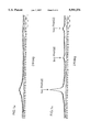
- FIG. 3 is a graph showing the relation between a magnetic flux density B and a magnetic field intensity with respect to the alloy of the present invention.
- FIG. 4 is a graph showing the relation between a magnetic flux density B and a magnetic field intensity with respect to the alloy of the present invention.
- B is an indispensable element, which is dissolved in a bcc Fe, effective for making the crystal grains ultrafine and controlling the alloy's magnetostriction and magnetic anisotropy.
- M is at least one element selected from Ti, Zr, Hf, V, Nb, Mo, Ta, Cr, W and Mn, which is also an indispensable element.
- the crystal grains can be made ultrafine, and the alloy's heat resistance can be improved.
- the M content (x), the B content (y) and the total content of M and B (x+y) should meet the following requirements:
- the alloy When x and y are lower than the above lower limits, the alloy has poor heat resistance. On the other hand, when x and y are larger than the above upper limits, the alloy has poor saturation magnetic flux density and soft magnetic properties. Particularly, the preferred ranges of x and y are:
- the alloys show excellent heat resistance.
- the above composition may further contain at least one element (X) selected from Si, Ge, P, Ga, Al and N, and at least one element (T) selected from Au, platinum group elements, Co, Ni, Sn, Be, Mg, Ca, Sr and Ba.
- element (X) selected from Si, Ge, P, Ga, Al and N
- element (T) selected from Au, platinum group elements, Co, Ni, Sn, Be, Mg, Ca, Sr and Ba.
- M represents at least one element selected from Ti, Zr, Hf, V, Nb, Mo, Ta, Cr, W and Mn,
- X represents at least one element selected from Si, Ge, P, Ga, Al and N, 4 ⁇ x ⁇ 15, 2 ⁇ y ⁇ 25, 0 ⁇ z ⁇ 10, and 7 ⁇ x+y+z ⁇ 35, at least 50% of the alloy structure being occupied by crystal grains having an average grain size of 500 ⁇ or less, and the crystal grains being based on a bcc structure.
- M represents at least one element selected from Ti, Zr, Hf, V, Nb, Mo, Ta, Cr, W and Mn,
- T represents at least one element selected from Au, platinum group elements, Co, Ni, Sn, Be, Mg, Ca, Sr and Ba, 4 ⁇ x ⁇ 15, 2 ⁇ y ⁇ 25, 0 ⁇ b ⁇ 10, and 7 ⁇ x+y+b ⁇ 35, at least 50% of the alloy structure being occupied by crystal grains having an average grain size of 500 ⁇ or less, and the crystal grains being based on a bcc structure.
- M represents at least one element selected from Ti, Zr, Hf, V, Nb, Mo, Ta, Cr, W and Mn,
- X represents at least one element selected from Si, Ge, P, Ca, Al and N,
- T represents at least one element selected from Au, platinum group elements, Co, Ni, Sn, Be, Mg, Ca, Sr and Ba, 4 ⁇ x ⁇ 15, 2 ⁇ y ⁇ 25, 0 ⁇ z ⁇ 10, 0 ⁇ b ⁇ 10, and 7 ⁇ x+y+z+b ⁇ 35, at least 50% of the alloy structure being occupied by crystal grains having an average grain size of 500 ⁇ or less, and the crystal grains being based on a bcc structure.
- the element X With respect to the element X, it is effective to control magnetostriction and magnetic anisotropy, and it may be added in an amount of 10 atomic % or less. When the amount of the element X exceeds 10 atomic %, the deterioration of soft magnetic properties takes place.
- the preferred amount of X is 0.5-8 atomic %.
- the amount of T (b) is preferably 10 atomic % or less. When it exceeds 10 atomic %, extreme decrease in a saturation magnetic flux density takes place.
- the preferred amount of T is 0.5-8 atomic %.
- the above-mentioned alloy of the present invention has a structure based on crystal grains having an average grain size of 500 ⁇ or less. Particularly when the average grain size is 200 ⁇ or less, excellent soft magnetic properties can be obtained.
- ultrafine crystal grains should be at least 50% of the alloy structure, because if otherwise, excellent soft magnetic properties would not be obtained.
- an amorphous phase may remain partially, or the alloy structure may become 100% crystalline. In either case, excellent soft magnetic properties can be obtained.
- M and B form ultrafine compounds based on bcc Fe and uniformly dispersed in the alloy structure by a heat treatment, suppressing the growth of such crystal grains. Accordingly, the magnetic anisotropy is apparently offset by this action of making the crystal grains ultrafine, resulting in excellent soft magnetic properties.
- a method of producing a magnetic alloy with ultrafine crystal grains comprising the steps of producing an amorphous alloy having either one of the above-mentioned compositions, and subjecting the resulting amorphous alloy to a heat treatment to cause crystallization, thereby providing the resulting alloy having a structure, at least 50% of which is occupied by crystal grains based on a bcc Fe solid solution and having an average grain size of 500 ⁇ or less.
- the amorphous alloy is usually produced by a liquid quenching method such as a single roll method, a double roll method, a rotating liquid spinning method, etc., by a gas phase quenching method such as a sputtering method, a vapor deposition method, etc.
- the amorphous alloy is subjected to a heat treatment in an inert gas atmosphere, in hydrogen or in vacuum to cause crystallization, so that at least 50% of the alloy structure is occupied by crystal grains based on a bcc structure solid solution and having an average grain size of 500 ⁇ or less.
- the heat treatment according to the present invention is preferably conducted at 450° C.-800° C.
- the heat treatment temperature is 500°-700° C.
- the heat treatment time is generally 1 minute to 200 hours, preferably 5 minutes to 24 hours. The heat treatment temperatures and time may be determined within the above ranges depending upon the compositions of the alloys.
- the alloy of the present invention undergoes a heat treatment at as high a temperature as 450°-800° C., glass bonding is easily conducted in the production of magnetic heads, providing the resulting magnetic heads with high reliability.
- the heat treatment of the alloy of the present invention can be conducted in a magnetic field.
- a magnetic field is applied in one direction, a magnetic anisotropy in one direction can be given to the resulting heat-treated alloy.
- a rotating magnetic field by conducting the heat treatment in a rotating magnetic field, further improvement in soft magnetic properties can be achieved.
- the heat treatment for crystallization can be followed by a heat treatment in a magnetic field.
- An alloy melt having a composition (atomic %) of 7% Nb, 18% B and balance substantially Fe was rapidly quenched by a single roll method to produce a thin amorphous alloy ribbon of 18 ⁇ m in thickness.
- FIG. 1 (a) The X-ray diffraction pattern of this amorphous alloy before a heat treatment is shown in FIG. 1 (a). It is clear from FIG. 1 (a) that this pattern is a halo pattern peculiar to an amorphous alloy.
- this thin alloy ribbon was subjected to a heat treatment at 600° C. for 1 hour in a nitrogen gas atmosphere to cause crystallization, and then cooled to room temperature.
- the X-ray diffraction pattern of the alloy obtained by the heat treatment at 600° C. is shown in FIG. 1 (b).
- the alloy after a 600° C. heat treatment had a structure mostly constituted by ultrafine crystal grains made of a bcc Fe solid solution having a small half-width.
- the alloy after the heat treatment had a structure mostly constituted by ultrafine crystal grains having an average grain size of 100 ⁇ or less.
- the percentage of ultrafine crystal grains is determined by a generally employed intersection method.
- the length of each crystal grains crossed by the line (L 1 , L 2 , L 3 . . . L n ) is summed to provide a total length (L 1 +L 2 +L 3 + . . . +L n ), and the total length is divided by L to determine the percentage of crystal grains.
- FIGS. 2 (a) and (b) show the results in FIGS. 2 (a) and (b).
- the alloy of the present invention can be obtained by crystallizing the corresponding amorphous alloy.
- the alloy of the present invention has extremely reduced magnetostriction than the amorphous counterpart, meaning that it is suitable as soft magnetic materials.
- the alloy of the present invention shows higher saturation magnetic flux density than the Fe-Si-Al alloy, and its ⁇ e1k exceeds 10000 in some cases. Therefore, the alloy of the present invention is suitable for magnetic heads for high-density magnetic recording, choke cores, high-frequency transformers, sensors, etc.
- Thin heat-treated alloy ribbons of 5 mm in width and 15 ⁇ m in thickness having the compositions shown in Table 1 were produced in the same manner as in Example 1. It was measured with respect to B 10 and Hc by a dc B-H tracer, an effective permeability ⁇ e1k at 1 kHz by an LCR meter, and a core loss Pc at 100 kHz and at 0.2 T by a U-function meter. The average crystal grain size and the percentage of crystal grains were determined by using the photomicrographs of the alloy structures. The results are shown in Table 1. Any of the heat-treated alloys had crystal grains based on a bcc structure and having an average grain size of 500 ⁇ or less.
- the alloys of the present invention show saturation magnetic flux densities equal to or higher than those of the Fe-Si-Al alloy and the Co-base amorphous alloy, and also have higher ⁇ e1k than those of the Fe-Si, etc. Accordingly, the alloys of the present invention are suitable as alloys for magnetic heads.
- Thin amorphous alloy ribbons of 5 mm in width and 15 ⁇ m in thickness having the compositions shown in Table 2 were produced by a single roll method. Next, each of these thin alloy ribbons was formed into a toroidal core of 19 mm in outer diameter and 15 mm in inner diameter, and subjected to a heat treatment at 550° C.-700° C. in an Ar gas atmosphere to cause crystallization.
- the alloys after the heat treatment had structures mostly constituted by ultrafine crystal grains based on a bcc structure and having an average grain size of 500 ⁇ or less.
- the alloys of the present invention show extremely larger ⁇ e1k 30 / ⁇ e1k than those of the conventional materials, and so excellent heat resistance, suffering from less deterioration of magnetic properties even at as high a temperature as 600° C. Accordingly, they are suitable as magnetic materials for magnetic heads needing glass bonding, sensors operated at high temperature, etc.
- the larger the B content the larger the value of ⁇ e1k 30 / ⁇ e1k .
- ⁇ e1k 30 / ⁇ e1k is low, meaning that the heat resistance is poor.
- Alloy layers having compositions shown in Table 3 were produced on fotoceram substrates by a sputtering method, and subjected to a heat treatment at 550°-700° C. for 1 hour to cause crystallization. At this stage, their ⁇ e1M 0 was measured.
- the alloys after the heat treatment had structures mostly constituted by ultrafine crystal grains based on a bcc structure and having an average grain size of 500 ⁇ or less.
- the alloy layers of the present invention show ⁇ e1M 1 / ⁇ e1M 0 closer to 1 than the alloys of Comparative Examples, and suffer from less deterioration of magnetic properties even at a high temperature, showing better heat resistance.
- the alloys of the present invention are suitable for producing high-reliability magnetic heads.
- magnetic alloy with ultrafine crystal grains having excellent saturation magnetic flux density, permeability and heat resistance can be produced.
Abstract
There is provided according to the present invention a magnetic alloy with ultrafine crystal grains having a composition represented by the general formula:
Fe.sub.100-x-y M.sub.x B.sub.y (atomic %)
wherein M represents at least one element selected from Ti, Zr, Hf, V, Nb, Mo, Ta, Cr, W and Mn, 4≦x≦15, 2≦y≦25, and 7≦x+y≦35, at least 50% of the alloy structure being occupied by crystal grains having an average grain size of 500 Å or less, and the crystal grains being based on a bcc structure. It may further contain X (Si, Ge, P, Ga, etc.) and/or T (Au, Co, Ni, etc.). This magnetic alloy has an excellent saturation magnetic flux density, permeability and heat resistance.
Description
This is a Continuation of application Ser. No. 07/896,878, filed Jun. 10, 1992, abandoned, which is a continuation of application Ser. No. 07/616,979 filed Nov. 21, 1990, abandoned.
The present invention relates to a magnetic alloy with ultrafine crystal grains excellent in magnetic properties and their stability, a major part of the alloy structure being occupied by ultrafine crystal grains, suitable for magnetic heads, etc.
Conventionally used as magnetic materials for magnetic parts such as magnetic heads are ferrites, showing relatively good frequency characteristics with small eddy current losses. However, ferrites do not have high saturation magnetic flux densities, so that they are insufficient for high-density magnetic recording of recent magnetic recording media when used for magnetic heads. In order that magnetic recording media having high coercive force for high-density magnetic recording show their performance sufficiently, magnetic materials having higher saturation magnetic flux densities and permeabilities are needed. To meet such demands, thin Fe-Al-Si alloy layers, thin Co-Nb-Zr amorphous alloy layers, etc. are recently investigated. Such attempts are reported by Shibata et al., NHK Technical Report 29 (2), 51-106 (1977), and by Hirota et al., Kino Zairyo (Functional Materials) August, 1986, p. 68, etc.
However, with respect to the Fe-Al-Si alloys, both magnetostriction λs and magnetic anisotropy K should be nearly zero to achieve high permeability. These alloys, however, achieve saturation magnetic flux densities of only 12 kG or so. Because of this problem, investigation is conducted to provide Fe-Si alloys having higher saturation magnetic flux densities and smaller magnetostrictions, but they are still insufficient in corrosion resistance and magnetic properties. In the case of the above Co-base amorphous alloys, they are easily crystallized when they have compositions suitable for higher saturation magnetic flux densities, meaning that they are poor in heat resistance, making their glass bonding difficult.
Recently, Fe-M-C (M=Ti, Zr, Hf) layers showing high saturation magnetic flux densities and permeabilities were reported in Tsushin Gakkai Giho (Telecommunications Association Technical Report) MR89-12, p. 9. However, carbon atoms contained in the alloy are easily movable, causing magnetic aftereffect, which in turn deteriorates the reliability of products made of such alloys.
Accordingly, an object of the present invention is to provide a magnetic alloy having excellent magnetic properties, heat resistance and reliability.
As a result of intense research in view of the above object, the inventors have found that a magnetic alloy based on Fe, M and B (M represents at least one element selected from Ti, Zr, Hf, V, Nb, Mo, Ta, Cr, W and Mn), at least 50% of the alloy structure being occupied by crystal grains having an average grain size of 500 Å or less, and the crystal grains being based on a bcc structure, has high saturation magnetic flux density and permeability and also good heat resistance, suitable for magnetic cores. The present invention has been made based upon this finding.
Thus, the magnetic alloy with ultrafine crystal grains according to the present invention has a composition represented by the general formula:
Fe.sub.100-x-y M.sub.x B.sub.y (atomic %)
wherein M represents at least one element selected from Ti, Zr, Hf, V, Nb, Mo, Ta, Cr, W and Mn, 4≦x≦15, 2≦y≦25, and 7≦x+y≦35, at least 50% of the alloy structure being occupied by crystal grains having an average grain size of 500 Å or less, and the crystal grains being based on a bcc structure.
FIG. 1 (a) is a graph showing an X-ray diffraction pattern of the alloy of the present invention before heat treatment;
FIG. 1 (b) is a graph showing an X-ray diffraction pattern of the alloy of the present invention heat-treated at 600° C.;
FIG. 2 (a) is a graph showing the relation between a saturation magnetic flux density (B10) and a heat treatment temperature; and
FIG. 2 (b) is a graph showing the relation between an effective permeability (μe1k) and a heat treatment temperature;
FIG. 3 is a graph showing the relation between a magnetic flux density B and a magnetic field intensity with respect to the alloy of the present invention; and
FIG. 4 is a graph showing the relation between a magnetic flux density B and a magnetic field intensity with respect to the alloy of the present invention.
In the above magnetic alloy of the present invention, B is an indispensable element, which is dissolved in a bcc Fe, effective for making the crystal grains ultrafine and controlling the alloy's magnetostriction and magnetic anisotropy.
M is at least one element selected from Ti, Zr, Hf, V, Nb, Mo, Ta, Cr, W and Mn, which is also an indispensable element. By the addition of both M and B, the crystal grains can be made ultrafine, and the alloy's heat resistance can be improved.
The M content (x), the B content (y) and the total content of M and B (x+y) should meet the following requirements:
4≦x≦15,
2≦y<25, and
7≦x+y≦35.
When x and y are lower than the above lower limits, the alloy has poor heat resistance. On the other hand, when x and y are larger than the above upper limits, the alloy has poor saturation magnetic flux density and soft magnetic properties. Particularly, the preferred ranges of x and y are:
5≦x≦15,
10<y<20, and
15<x+y≦30.
With these ranges, the alloys show excellent heat resistance.
According to another aspect of the present invention, the above composition may further contain at least one element (X) selected from Si, Ge, P, Ga, Al and N, and at least one element (T) selected from Au, platinum group elements, Co, Ni, Sn, Be, Mg, Ca, Sr and Ba.
Accordingly, the following alloys are also included in the present application.
The magnetic alloy with ultrafine crystal grains according to another embodiment of the present invention has a composition represented by the general formula:
Fe100-x-y-z Mx By Xz (atomic %)
wherein
M represents at least one element selected from Ti, Zr, Hf, V, Nb, Mo, Ta, Cr, W and Mn,
X represents at least one element selected from Si, Ge, P, Ga, Al and N, 4≦x≦15, 2≦y≦25, 0≦z≦10, and 7≦x+y+z≦35, at least 50% of the alloy structure being occupied by crystal grains having an average grain size of 500 Å or less, and the crystal grains being based on a bcc structure.
The magnetic alloy with ultrafine crystal grains according to a further embodiment of the present invention has a composition represented by the general formula:
Fe.sub.100-x-y-b M.sub.x B.sub.y T.sub.b (atomic %)
wherein
M represents at least one element selected from Ti, Zr, Hf, V, Nb, Mo, Ta, Cr, W and Mn,
T represents at least one element selected from Au, platinum group elements, Co, Ni, Sn, Be, Mg, Ca, Sr and Ba, 4≦x≦15, 2≦y≦25, 0<b ≦10, and 7≦x+y+b≦35, at least 50% of the alloy structure being occupied by crystal grains having an average grain size of 500 Å or less, and the crystal grains being based on a bcc structure.
The magnetic alloy with ultrafine crystal grains according to a still further embodiment of the present invention has a composition represented by the general formula:
Fe.sub.100-x-y-z-b M.sub.x B.sub.y X.sub.z T.sub.b (atomic %)
wherein
M represents at least one element selected from Ti, Zr, Hf, V, Nb, Mo, Ta, Cr, W and Mn,
X represents at least one element selected from Si, Ge, P, Ca, Al and N,
T represents at least one element selected from Au, platinum group elements, Co, Ni, Sn, Be, Mg, Ca, Sr and Ba, 4≦x≦15, 2≦y≦25, 0≦z≦10, 0≦b≦10, and 7≦x+y+z+b≦35, at least 50% of the alloy structure being occupied by crystal grains having an average grain size of 500 Å or less, and the crystal grains being based on a bcc structure.
With respect to the element X, it is effective to control magnetostriction and magnetic anisotropy, and it may be added in an amount of 10 atomic % or less. When the amount of the element X exceeds 10 atomic %, the deterioration of soft magnetic properties takes place. The preferred amount of X is 0.5-8 atomic %.
With respect to the element T, it is effective to improve corrosion resistance and to control magnetic properties. The amount of T (b) is preferably 10 atomic % or less. When it exceeds 10 atomic %, extreme decrease in a saturation magnetic flux density takes place. The preferred amount of T is 0.5-8 atomic %.
The above-mentioned alloy of the present invention has a structure based on crystal grains having an average grain size of 500 Å or less. Particularly when the average grain size is 200 Å or less, excellent soft magnetic properties can be obtained.
In the present invention, ultrafine crystal grains should be at least 50% of the alloy structure, because if otherwise, excellent soft magnetic properties would not be obtained.
Depending upon the heat treatment conditions, an amorphous phase may remain partially, or the alloy structure may become 100% crystalline. In either case, excellent soft magnetic properties can be obtained.
The reason why excellent soft magnetic properties can be obtained in the magnetic alloy with ultrafine crystal grains of the present invention are considered as follows: In the present invention, M and B form ultrafine compounds based on bcc Fe and uniformly dispersed in the alloy structure by a heat treatment, suppressing the growth of such crystal grains. Accordingly, the magnetic anisotropy is apparently offset by this action of making the crystal grains ultrafine, resulting in excellent soft magnetic properties.
According to a further aspect of the present invention, there is provided a method of producing a magnetic alloy with ultrafine crystal grains comprising the steps of producing an amorphous alloy having either one of the above-mentioned compositions, and subjecting the resulting amorphous alloy to a heat treatment to cause crystallization, thereby providing the resulting alloy having a structure, at least 50% of which is occupied by crystal grains based on a bcc Fe solid solution and having an average grain size of 500 Å or less.
The amorphous alloy is usually produced by a liquid quenching method such as a single roll method, a double roll method, a rotating liquid spinning method, etc., by a gas phase quenching method such as a sputtering method, a vapor deposition method, etc. The amorphous alloy is subjected to a heat treatment in an inert gas atmosphere, in hydrogen or in vacuum to cause crystallization, so that at least 50% of the alloy structure is occupied by crystal grains based on a bcc structure solid solution and having an average grain size of 500 Å or less.
The heat treatment according to the present invention is preferably conducted at 450° C.-800° C. When the heat treatment is lower than 450° C., crystallization is difficult even though the heat treatment is conducted for a long period of time. On the other hand, when it exceeds 800° C., the crystal grains grow excessively, failing to obtain the desired ultrafine crystal grains. The preferred heat treatment temperature is 500°-700° C. Incidentally, the heat treatment time is generally 1 minute to 200 hours, preferably 5 minutes to 24 hours. The heat treatment temperatures and time may be determined within the above ranges depending upon the compositions of the alloys.
Since the alloy of the present invention undergoes a heat treatment at as high a temperature as 450°-800° C., glass bonding is easily conducted in the production of magnetic heads, providing the resulting magnetic heads with high reliability.
The heat treatment of the alloy of the present invention can be conducted in a magnetic field. When a magnetic field is applied in one direction, a magnetic anisotropy in one direction can be given to the resulting heat-treated alloy. Also, by conducting the heat treatment in a rotating magnetic field, further improvement in soft magnetic properties can be achieved. In addition, the heat treatment for crystallization can be followed by a heat treatment in a magnetic field.
The present invention will be explained in further detail by way of the following Examples, without intending to restrict the scope of the present invention.
An alloy melt having a composition (atomic %) of 7% Nb, 18% B and balance substantially Fe was rapidly quenched by a single roll method to produce a thin amorphous alloy ribbon of 18 μm in thickness.
The X-ray diffraction pattern of this amorphous alloy before a heat treatment is shown in FIG. 1 (a). It is clear from FIG. 1 (a) that this pattern is a halo pattern peculiar to an amorphous alloy.
Next, this thin alloy ribbon was subjected to a heat treatment at 600° C. for 1 hour in a nitrogen gas atmosphere to cause crystallization, and then cooled to room temperature.
The X-ray diffraction pattern of the alloy obtained by the heat treatment at 600° C. is shown in FIG. 1 (b). As a result of X-ray diffraction analysis, it was confirmed that the alloy after a 600° C. heat treatment had a structure mostly constituted by ultrafine crystal grains made of a bcc Fe solid solution having a small half-width.
As a result of transmission electron photomicrography, it was confirmed that the alloy after the heat treatment had a structure mostly constituted by ultrafine crystal grains having an average grain size of 100 Å or less.
Incidentally, in the present invention, the percentage of ultrafine crystal grains is determined by a generally employed intersection method. In this method, an arbitrary line (length=L) is drawn on a photomicrograph such that it crosses crystal grains in the photomicrograph. The length of each crystal grains crossed by the line (L1, L2, L3 . . . Ln) is summed to provide a total length (L1 +L2 +L3 + . . . +Ln), and the total length is divided by L to determine the percentage of crystal grains.
Where there are a large percentage of crystal grains in the alloy structure, it appears from the photomicrograph that the structure is almost occupied by crystal grains. However, even in this case, some percentage of an amorphous phase exists in the structure. This is because the periphery of each crystal grain looks obscure in the photomicrograph, suggesting the existence of an amorphous phase. Where there are a large percentage of such crystal grains, it is generally difficult to express the percentage of crystal grains by an accurate numerical value. Accordingly, in Examples, "substantially" or "mostly" is used.
Next, a toroidal core produced by the amorphous alloy of this composition was subjected to a heat treatment at various heat treatment temperatures without applying a magnetic field to measure a dc B-H hysteresis curve by a dc B-H tracer and an effective permeability μe1k at 1 kHz by an LCR meter. The heat treatment time was 1 hour, and the heat treatment atmosphere was a nitrogen gas atmosphere. The results are shown in FIGS. 2 (a) and (b). FIG. 3 shows the dc B-H hysteresis curve of Fe75 Nb7 B18 heated at 630° C. for 1 hour, in which B10 =12.1 kG, Br/B10 =24%, and Hc=0.103 Oe.
It can be confirmed that at a heat treatment temperature higher than the crystallization temperature at which bcc Fe phases are generated, high saturation magnetic flux density and high permeability are obtained.
Thus, the alloy of the present invention can be obtained by crystallizing the corresponding amorphous alloy. The alloy of the present invention has extremely reduced magnetostriction than the amorphous counterpart, meaning that it is suitable as soft magnetic materials.
The alloy of the present invention shows higher saturation magnetic flux density than the Fe-Si-Al alloy, and its μe1k exceeds 10000 in some cases. Therefore, the alloy of the present invention is suitable for magnetic heads for high-density magnetic recording, choke cores, high-frequency transformers, sensors, etc.
Thin heat-treated alloy ribbons of 5 mm in width and 15 μm in thickness having the compositions shown in Table 1 were produced in the same manner as in Example 1. It was measured with respect to B10 and Hc by a dc B-H tracer, an effective permeability μe1k at 1 kHz by an LCR meter, and a core loss Pc at 100 kHz and at 0.2 T by a U-function meter. The average crystal grain size and the percentage of crystal grains were determined by using the photomicrographs of the alloy structures. The results are shown in Table 1. Any of the heat-treated alloys had crystal grains based on a bcc structure and having an average grain size of 500 Å or less. The dc hysteresis curve of No. 1 alloy (Fe79 Nb7 B14) shown in Table 1 is shown in FIG. 4, in which B10 =12.5 kG, Br/B10 =72%, and Hc=0.200 Oe.
The alloys of the present invention show saturation magnetic flux densities equal to or higher than those of the Fe-Si-Al alloy and the Co-base amorphous alloy, and also have higher μe1k than those of the Fe-Si, etc. Accordingly, the alloys of the present invention are suitable as alloys for magnetic heads.
                                  TABLE 1
__________________________________________________________________________
                Average
                     Crystal
                Grain
                     Grain
Sample
    Composition Size Content
                          B.sub.10    Pc
No.*
    (atomic %)  (Å)
                     (%)  (kG)
                             Hc (Oe)
                                  μ.sub.elk
                                      (mW/cc)
__________________________________________________________________________
 1  Fe.sub.bal Nb.sub.7 B.sub.14
                80   90   12.7
                             0.19 4000
                                      1900
 2  Fe.sub.bal Hf.sub.6 B.sub.13
                75   about
                          14.1
                             0.38 3300
                                      2200
                     100
 3  Fe.sub.bal Ta.sub.7.8 B.sub.18
                60   95   12.4
                             0.28 7800
                                       890
 4  Fe.sub.bal Nb.sub.6 B.sub.17
                65   90   13.5
                             0.11 14800
                                       520
 5  Fe.sub.bal Ti.sub.11 B.sub.13.2 Si.sub.0.9
                95   95   12.2
                             0.42 3300
                                      2400
 6  Fe.sub.bal Zr.sub.6.5 B.sub.14.3 Ge.sub.1.0
                85   95   14.3
                             0.32 3900
                                      1700
 7  Fe.sub.bal Hf.sub.6.3 B.sub.12 Ga.sub.0.4
                85   about
                          14.2
                             0.29 5700
                                      1100
                     100
 8  Fe.sub.bal Zr.sub.6.5 B.sub.15.9 Al.sub.1.2
                72   90   14.7
                             0.38 3800
                                      2500
 9  Fe.sub.bal Nb.sub.6.7 B.sub.12 P.sub.0.5
                95   about
                          14.1
                             0.39 3600
                                      2200
                     100
10  Fe.sub.bal Mo.sub.8.0 B.sub.18 Al.sub.1.4 Au.sub.0.5
                110  85   12.2
                             0.39 2900
                                      2200
11  Fe.sub.bal Ti.sub.7.5 B.sub.14.2 Ga.sub.1.2 Ag.sub.0.1
                130  80   13.9
                             0.37 2900
                                      2100
12  Fe.sub.bal Zr.sub.8.7 B.sub.17.3 P.sub.1.2
                85   95   13.7
                             0.33 3600
                                      1900
13  Fe.sub.bal Hf.sub.10 B.sub.20 Si.sub.1.1 Ru.sub.2.1
                80   90   12.2
                             0.28 5600
                                      1000
14  Fe.sub.bal Ta.sub.8.2 B.sub.14.5 N.sub.0.1 Co.sub.9.9
                75   75   13.4
                             0.22 5200
                                       870
15  Fe.sub.bal Nb.sub.6.7 B.sub.11 Ge.sub.1.1 Ni.sub.8.7
                75   about
                          13.5
                             0.35 3300
                                      1600
                     100
16  Fe.sub.bal Ti.sub.8.8 B.sub.11.2 Sn.sub.1.8 Mg.sub.0.1
                120  90   14.3
                             0.33 3000
                                      2200
17  Fe.sub.bal Zr.sub.10.6 B.sub.12.8 Be.sub.1 Rh.sub.1.4
                85   90   13.9
                             0.32 4100
                                      2100
18  Fe.sub.bal Al.sub.7.6 Si.sub.17.9 Layer
                --   --   10.3
                             --   1500
                                      --
19  Fe.sub.bal Si.sub.12.5 Layer
                --   --   17.6
                             --    400
                                      --
20  Co.sub.bal Fe.sub.4.7 Si.sub.15.0 B.sub.10
                --   --    8.0
                              0.006
                                  8500
                                       350
    Amorphous
__________________________________________________________________________
 Note*:
 Sample Nos. 1-17: Present invention.
 Sample Nos. 18-20: Conventional alloy.
Thin amorphous alloy ribbons of 5 mm in width and 15 μm in thickness having the compositions shown in Table 2 were produced by a single roll method. Next, each of these thin alloy ribbons was formed into a toroidal core of 19 mm in outer diameter and 15 mm in inner diameter, and subjected to a heat treatment at 550° C.-700° C. in an Ar gas atmosphere to cause crystallization.
As a result of X-ray diffraction analysis and transmission electron photomicrography, it was confirmed that the alloys after the heat treatment had structures mostly constituted by ultrafine crystal grains based on a bcc structure and having an average grain size of 500 Å or less.
With respect to newly prepared thin amorphous alloy ribbons having the above-mentioned compositions, they were formed into toroidal cores in the same manner as above and measured on effective permeability μe1k at 1 kHz. Next, they were subjected to a heat treatment at 600° C. for 30 minutes and cooled to room temperature. Their effective permeabilities (μe1k 30) at 1 kHz were also measured. The values of μe1k 30 /μe1k are shown in Table 2.
              TABLE 2
______________________________________
                      Average  Crystal
                      Grain    Grain
Sample
      Composition     Size     Content
                                      μ.sub.elk.sup.30 /
No.*  (atomic %)      (Å)  (%)    μ.sub.elk
______________________________________
21    Fe.sub.bal Zr.sub.8 B.sub.14
                       70      95     0.85
22    Fe.sub.bal Hf.sub.7 B.sub.16
                       55      85     0.82
23    Fe.sub.bal Ta.sub.7 B.sub.17
                       60      90     0.83
24    Fe.sub.bal Nb.sub.8 B.sub.19
                       65      95     0.87
25    Fe.sub.bal Hf.sub.8 Mn.sub.1.5 B.sub.13 Ga.sub.2
                       80      about  0.79
                               100
26    Fe.sub.bal Zr.sub.9 B.sub.16 Al.sub.2
                       85      95     0.80
27    Fe.sub.bal Ti.sub.11 B.sub.19 Ga.sub.0.5
                      120      90     0.88
28    Fe.sub.bal Zr.sub.13 B.sub.17 P.sub.0.5
                       90      80     0.87
29    Fe.sub.bal Hf.sub.10 B.sub.15 Si.sub.2 Ru.sub.2
                      110      80     0.82
      Co.sub.5
30    Fe.sub.bal Nb.sub.8 B.sub.13 Ge.sub.1 Ni.sub.1
                      120      80     0.77
31    Fe.sub.bal Zr.sub.6 B.sub.14 Be.sub.0.5 Rh.sub.2
                      220      85     0.76
32    Fe.sub.bal Nb.sub.5 B.sub.11
                      240      90     0.72
33    Fe.sub.bal Zr.sub.5 B.sub.11
                      160      about  0.73
                               100
34    Fe.sub.bal Nb.sub.7 B.sub.7
                      180      about  0.65
                               95
35    Fe.sub.bal Zr.sub.6 B.sub.5
                      240      about  0.63
                               100
36    Fe.sub.bal Ta.sub.7 B.sub.7
                      230      about  0.66
                               100
37    Fe.sub.bal Ti.sub.8 B.sub.4
                      220      about  0.62
                               100
38    Fe.sub.bal W.sub.5 B.sub.8
                      210      about  0.68
                               100
39    Co.sub.bal Fe.sub.4.7 Si.sub.15 B.sub.10
                      --        0     almost 0
      Amorphous
40    Fe.sub.bal Si.sub.9 B.sub.13
                      --        0     almost 0
      Amorphous
41    Co.sub.bal Nb.sub.10 Zr.sub.3
                      --        0     almost 0
      Amorphous
42    Fe.sub.bal Zr.sub.1 B.sub.9
                      240      100    0.35
43    Fe.sub.bal Hf.sub.2 B.sub.8
                      220      100    0.38
______________________________________
 Note*:
 Sample Nos. 21-38: Present invention.
 Sample Nos. 39-43: Comparative Examples.
It is clear from Table 2 that the alloys of the present invention show extremely larger μe1k 30 /μe1k than those of the conventional materials, and so excellent heat resistance, suffering from less deterioration of magnetic properties even at as high a temperature as 600° C. Accordingly, they are suitable as magnetic materials for magnetic heads needing glass bonding, sensors operated at high temperature, etc.
Incidentally, in the alloy of the present invention, the larger the B content, the larger the value of μe1k 30 /μe1k. In addition, when the M content is smaller than the lower limit of the range of the present invention, μe1k 30 /μe1k is low, meaning that the heat resistance is poor.
Alloy layers having compositions shown in Table 3 were produced on fotoceram substrates by a sputtering method, and subjected to a heat treatment at 550°-700° C. for 1 hour to cause crystallization. At this stage, their μe1M 0 was measured.
As a result of X-ray diffraction analysis and transmission electron photomicrography, it was confirmed that the alloys after the heat treatment had structures mostly constituted by ultrafine crystal grains based on a bcc structure and having an average grain size of 500 Å or less.
Next, these alloys were introduced into an oven at 550° C., and kept for 1 hour and cooled to room temperature to measure their μe1M 1. Their μe1M 1 /μe1M 0 ratios are shown in Table 3.
              TABLE 3
______________________________________
                      Average  Crystal
                      Grain    Grain
Sample
      Composition     Size     Content
                                      μ.sub.elM.sup.1 /
No.*  (atomic %)      (Å)  (%)    μ.sub.elM.sup.0
______________________________________
44    Fe.sub.bal Zr.sub.8.9 B.sub.18.5
                      65       85     0.91
45    Fe.sub.bal Hf.sub.7.7 B.sub.16.7
                      70       90     0.90
46    Fe.sub.bal Ta.sub.7.9 B.sub.15.1
                      60       95     0.89
47    Fe.sub.bal Nb.sub.8.2 B.sub.14.5
                      60       80     0.91
48    Fe.sub.bal Cr.sub.12.1 B.sub.19.1 Si.sub.1.5
                      290      about  0.91
                               95
49    Fe.sub.bal W.sub.8.9 B.sub.14.5 Ge.sub.1.4
                      130      about  0.92
                               85
50    Fe.sub.bal Mn.sub.12.9 B.sub.15.8 P.sub.0.8
                      380      about  0.93
                               80
51    Fe.sub.bal Hf.sub.8.6 B.sub.12.8 Ga.sub.1.4
                      60       about  0.91
                               100
52    Fe.sub.bal Zr.sub.8.6 B.sub.16.9 Al.sub.1.4
                      75       about  0.96
                               100
53    Fe.sub.bal Nb.sub.8.8 B.sub.14.9 N.sub.0.9
                      55       about  0.92
                               100
54    Fe.sub.bal Mo.sub.11.0 B.sub.17.8 Al.sub.1.2
                      120      75     0.91
      Au.sub.1.1
55    Fe.sub.bal Ti.sub.10.6 B.sub.17.6 Ga.sub.0.9
                      130      85     0.90
56    Fe.sub.bal Zr.sub.12.7 B.sub.17.3 P.sub.2.1
                      90       90     0.89
57    Fe.sub.bal Hf.sub.9.9 B.sub.14.8 Si.sub.1.1
                      85       95     0.91
      Ru.sub.1.6
58    Fe.sub.bal Ta.sub.8.2 B.sub.13.8 N.sub.0.1
                      55       about  0.92
      Co.sub.8.9               100
59    Fe.sub.bal Nb.sub.7.7 B.sub.19.8 Ge.sub.1.8
                      65       85     0.90
      Ni.sub.5.7
60    Fe.sub.bal Ti.sub.8.8 B.sub.17.2 Pt.sub.0.1
                      140      80     0.90
      Sn.sub.1.1 Mg.sub.0.1 Co.sub.1.2
61    Fe.sub.bal Zr.sub.10.2 B.sub.15.6 Ge.sub.0.2
                      70       75     0.92
      Rh.sub.1.8
62    Fe--C Layer     200      about  almost 0
      Co.sub.8.9               100
63    Fe--N Layer     230      about  almost 0
      Co.sub.8.9               100
______________________________________
 Note*:
 Sample Nos. 44-61: Present invention.
 Sample Nos. 62-63: Conventional alloy layer.
The alloy layers of the present invention show μe1M 1 /μe1M 0 closer to 1 than the alloys of Comparative Examples, and suffer from less deterioration of magnetic properties even at a high temperature, showing better heat resistance. Thus, the alloys of the present invention are suitable for producing high-reliability magnetic heads.
According to the present invention, magnetic alloy with ultrafine crystal grains having excellent saturation magnetic flux density, permeability and heat resistance can be produced.
Claims (25)
1. A magnetic core consisting essentially of a soft magnetic alloy with ultrafine crystal grains having a composition represented by the general formula consisting essentially of:
Fe.sub.100-x-y M.sub.x B.sub.y (atomic %)
wherein
M represents at least one element selected from the group consisting of Ti, Zr, Hf, V, Nb, Mo, Ta, Cr, W and Mn, 4≦x≦15, 2≦y≦25, and 7≦x+y≦35, at least 50% of the alloy structure being occupied by crystal grains having an average grain size of 240 Å or less, said crystal grains being based on a bcc structure, and said magnetic core having μe1k of 2900 or more and μe1k 30 /μe1k of 0.62 or more wherein μe1k represents an effective permeability at 1 kHz and μe1k represents an effective permeability at 1 kHz after heat treatment at 600° C. for 30 minutes.
2. A magnetic core consisting essentially of a soft magnetic alloy with ultrafine crystal grains having a composition represented by the general formula consisting essentially of:
Fe.sub.100-x-y-z M.sub.x B.sub.y X.sub.z (atomic %)
wherein
M represents at least one element selected from the group consisting of Ti, Zr, Hf, V, Nb, Mo, Ta, Cr, W and Mn,
X represents at least one element selected from the group consisting of Si, Ge, P, Ga, and Al, 4≦x≦15, 2≦y ≦25, 0≦z≦10, 7≦x+y+z≦35, at least 50% of the alloy structure being occupied by crystal grains having an average grain size of 240 Å or less, said crystal grains being based on a bcc structure, and said magnetic core having μe1k of 2900 or more and μe1k 30 /μe1k of 0.62 or more wherein μe1k represents an effective permeability at 1 kH and μe1k 30 represents an effective permeability at 1 kHz after heat treatment at 600° C. for 30 minutes.
3. A magnetic core consisting essentially of a soft magnetic alloy with ultrafine crystal grains having a composition represented by general formula consisting essentially of:
Fe.sub.100-x-y-b M.sub.x B.sub.y T.sub.b (atomic %)
wherein
M represents at least one element selected from the group consisting of Ti, Zr, Hf, V, Nb, Mo, Ta, Cr, W and Mn,
T represents at least one element selected from the group consisting of platinum group elements, Co, Ni, Be, Mg, Ca, Sr and Ba, 4≦x≦15, 2≦y≦25, 0≦b≦10, and 7≦x+y+b≦35, at least 50% of the alloy structure being occupied by crystal grains having an average grain size of 240 Å or less, said crystal grains being based on a bcc structure, and said magnetic core having μe1k of 2900 or more and μe1k 30 /μe1k of 0.62 or more wherein μe1k represents an effective permeability at 1 kHz and μe1k 30 represents an effective permeability at 1 kHz after heat treatment at 600° C. for 30 minutes.
4. A magnetic core consisting essentially of a soft magnetic alloy with ultrafine crystal grains having a composition represented by general formula consisting essentially of:
Fe.sub.100-x-y-z-b M.sub.x B.sub.y X.sub.z T.sub.b (atomic %)
wherein
M represents at least one element selected from the group consisting of Ti, Zr, Hf, V, Nb, Mo, Ta, Cr, W and Mn,
X represents at least one element selected from the group consisting of Si, Ge, P, and Al,
T represents at least one element selected from the group consisting of platinum group elements, Co, Ni, Be, Mg, Ca, Sr and Ba, 4≦x≦15, 2≦y≦25, 0≦z≦10, 0≦b≦10, 7≦x+y+z+b≦35, at least 50% of the alloy structure being occupied by crystal grains having an average grain size of 240 Å or less, said crystal grains being based on a bcc structure, and said magnetic core having μe1k of 2900 or more and μe1k 30 /μe1k of 0.62 or more wherein μe1k represents an effective permeability at 1 kHz and μe1k 30 represents an effective permeability at 1 kHz after heat treatment at 600° C. for 30 minutes.
5. The magnetic core according to claim 1, wherein the balance of said alloy structure is composed of an amorphous phase.
6. The magnetic core according to claim 2, wherein the balance of said alloy structure is composed of an amorphous phase.
7. The magnetic core according to claim 3, wherein the balance of said alloy structure is composed of an amorphous phase.
8. The magnetic core according to claim 4, wherein the balance of said alloy structure is composed of an amorphous phase.
9. The magnetic core according to claim 1, wherein said alloy is substantially composed of a crystalline phase.
10. The magnetic core according to claim 2, wherein said alloy is substantially composed of a crystalline phase.
11. The magnetic core according to claim 3, wherein said alloy is substantially composed of a crystalline phase.
12. The magnetic core according to claim 4, wherein said alloy is substantially composed of a crystalline phase.
13. The magnetic core according to claim 1, wherein said y satisfies 10<y≦20.
14. The magnetic core according to claim 2, wherein said y satisfies 10<y≦20.
15. The magnetic core according to claim 3, wherein said y satisfies 10<y≦20.
16. The magnetic core according to claim 4, wherein said y satisfies 10<y≦20.
17. The magnetic core according to claim 5, wherein said y satisfies 10<y≦20.
18. The magnetic core according to claim 6, wherein said y satisfies 10<y≦20.
19. The magnetic core according to claim 1, wherein said crystal grains have an average grain size of 200 Å or less.
20. The magnetic core according to claim 2, wherein said crystal grains have an average grain size of 200 Å or less.
21. The magnetic core according to claim 3, wherein said crystal grains have an average grain size of 200 Å or less.
22. The magnetic core according to claim 4, wherein said crystal grains have an average grain size of 200 Å or less.
23. The magnetic core according to claim 5, wherein said crystal grains have an average grain size of 200 Å or less.
24. The magnetic core according to claim 6, wherein said crystal grains have an average grain size of 200 Å or less.
25. The magnetic core according to claim 7, wherein said crystal grains have an average grain size of 200 Å or less.
Priority Applications (1)
| Application Number | Priority Date | Filing Date | Title |
|---|---|---|---|
| US08/154,715 US5591276A (en) | 1989-11-22 | 1993-11-19 | Magnetic alloy with ultrafine crystal grains and method of producing same |
Applications Claiming Priority (5)
| Application Number | Priority Date | Filing Date | Title |
|---|---|---|---|
| JP1-303617 | 1989-11-22 | ||
| JP30361789 | 1989-11-22 | ||
| US61697990A | 1990-11-21 | 1990-11-21 | |
| US89687892A | 1992-06-10 | 1992-06-10 | |
| US08/154,715 US5591276A (en) | 1989-11-22 | 1993-11-19 | Magnetic alloy with ultrafine crystal grains and method of producing same |
Related Parent Applications (1)
| Application Number | Title | Priority Date | Filing Date |
|---|---|---|---|
| US89687892A Continuation | 1989-11-22 | 1992-06-10 |
Publications (1)
| Publication Number | Publication Date |
|---|---|
| US5591276A true US5591276A (en) | 1997-01-07 |
Family
ID=17923146
Family Applications (1)
| Application Number | Title | Priority Date | Filing Date |
|---|---|---|---|
| US08/154,715 Expired - Lifetime US5591276A (en) | 1989-11-22 | 1993-11-19 | Magnetic alloy with ultrafine crystal grains and method of producing same |
Country Status (5)
| Country | Link |
|---|---|
| US (1) | US5591276A (en) |
| EP (1) | EP0430085B1 (en) |
| KR (1) | KR930012182B1 (en) |
| CA (1) | CA2030446C (en) |
| DE (1) | DE69009152T2 (en) |
Cited By (16)
| Publication number | Priority date | Publication date | Assignee | Title |
|---|---|---|---|---|
| US5833770A (en) * | 1996-02-26 | 1998-11-10 | Alps Electric Co., Ltd. | High frequency soft magnetic alloy and plane magnetic element, antenna and wave absorber comprising the same |
| US6083325A (en) * | 1996-07-15 | 2000-07-04 | Alps Electric Co., Ltd. | Method for making Fe-based soft magnetic alloy |
| US6332933B1 (en) | 1997-10-22 | 2001-12-25 | Santoku Corporation | Iron-rare earth-boron-refractory metal magnetic nanocomposites |
| US6352599B1 (en) | 1998-07-13 | 2002-03-05 | Santoku Corporation | High performance iron-rare earth-boron-refractory-cobalt nanocomposite |
| WO2004088681A2 (en) * | 2003-04-02 | 2004-10-14 | Vacuumschmelze Gmbh & Co. Kg | Magnet core, method for the production of such a magnet core, uses of such a magnet core especially in current transformers and current-compensated inductors, and alloys and bands used for producing such a magnet core |
| US20060042938A1 (en) * | 2004-09-01 | 2006-03-02 | Heraeus, Inc. | Sputter target material for improved magnetic layer |
| US20060286414A1 (en) * | 2005-06-15 | 2006-12-21 | Heraeus, Inc. | Enhanced oxide-containing sputter target alloy compositions |
| EP1850334A1 (en) * | 2006-04-27 | 2007-10-31 | Heraeus, Inc. | Soft magnetic underlayer in magnetic media and soft magnetic alloy based sputter target |
| US20110031432A1 (en) * | 2009-08-04 | 2011-02-10 | The Boeing Company | Mechanical improvement of rare earth permanent magnets |
| JP2019186327A (en) * | 2018-04-05 | 2019-10-24 | パナソニックIpマネジメント株式会社 | Magnetostrictive material and magnetostrictive type device arranged by use thereof |
| US20200161034A1 (en) * | 2018-11-15 | 2020-05-21 | Rogers Corporation | High frequency magnetic films, method of manufacture, and uses thereof |
| CN113557315A (en) * | 2019-01-11 | 2021-10-26 | 蒙纳士大学 | Iron-based alloy |
| US11679991B2 (en) | 2019-07-30 | 2023-06-20 | Rogers Corporation | Multiphase ferrites and composites comprising the same |
| US11691892B2 (en) | 2020-02-21 | 2023-07-04 | Rogers Corporation | Z-type hexaferrite having a nanocrystalline structure |
| US11783975B2 (en) | 2019-10-17 | 2023-10-10 | Rogers Corporation | Nanocrystalline cobalt doped nickel ferrite particles, method of manufacture, and uses thereof |
| US11827527B2 (en) | 2019-09-24 | 2023-11-28 | Rogers Corporation | Bismuth ruthenium M-type hexaferrite |
Families Citing this family (16)
| Publication number | Priority date | Publication date | Assignee | Title |
|---|---|---|---|---|
| CA2040741C (en) * | 1990-04-24 | 2000-02-08 | Kiyonori Suzuki | Fe based soft magnetic alloy, magnetic materials containing same, and magnetic apparatus using the magnetic materials |
| JPH0681086A (en) * | 1992-09-03 | 1994-03-22 | Hitachi Metals Ltd | Alloy having ultrafine crystalline-grained structure excellent in corrosion resistance |
| CA2151691A1 (en) * | 1994-07-08 | 1996-01-09 | Peter Yongxin Zhou | High response electronic article surveillance system responders and methods for making same |
| US5755986A (en) * | 1995-09-25 | 1998-05-26 | Alps Electric Co., Ltd. | Soft-magnetic dielectric high-frequency composite material and method for making the same |
| JP3620784B2 (en) * | 1998-08-25 | 2005-02-16 | 日立金属株式会社 | Magnetic core for high-frequency acceleration cavity and high-frequency acceleration cavity using the same |
| US6462456B1 (en) * | 1998-11-06 | 2002-10-08 | Honeywell International Inc. | Bulk amorphous metal magnetic components for electric motors |
| US6803694B2 (en) | 1998-11-06 | 2004-10-12 | Metglas, Inc. | Unitary amorphous metal component for an axial flux electric machine |
| US6737784B2 (en) | 2000-10-16 | 2004-05-18 | Scott M. Lindquist | Laminated amorphous metal component for an electric machine |
| US7144468B2 (en) | 2002-09-05 | 2006-12-05 | Metglas, Inc. | Method of constructing a unitary amorphous metal component for an electric machine |
| US6784588B2 (en) | 2003-02-03 | 2004-08-31 | Metglas, Inc. | Low core loss amorphous metal magnetic components for electric motors |
| US7235910B2 (en) | 2003-04-25 | 2007-06-26 | Metglas, Inc. | Selective etching process for cutting amorphous metal shapes and components made thereof |
| KR100838732B1 (en) * | 2006-12-20 | 2008-06-17 | 주식회사 포스코 | Fe-based bulk amorphous alloys with high glass forming ability |
| KR100838733B1 (en) * | 2006-12-20 | 2008-06-17 | 주식회사 포스코 | Fe-based bulk amorphous alloys with optimum cr/mo composition |
| CN109778085B (en) * | 2019-03-14 | 2020-04-17 | 安徽智磁新材料科技有限公司 | Amorphous alloy with good toughness and preparation method thereof |
| CN110468353B (en) * | 2019-08-21 | 2021-12-21 | 江苏中科启航新材料工业研究院有限公司 | High-saturation magnetic induction intensity iron-based amorphous alloy and preparation method thereof |
| KR102220790B1 (en) * | 2020-07-30 | 2021-03-02 | (주)그라미 | Functional decorative plate and its manufacturing method |
Citations (11)
| Publication number | Priority date | Publication date | Assignee | Title |
|---|---|---|---|---|
| US4312683A (en) * | 1979-09-05 | 1982-01-26 | Matsushita Electric Industrial Co., Ltd. | Method for heat-treating amorphous alloy films |
| JPS57190304A (en) * | 1981-05-19 | 1982-11-22 | Hitachi Metals Ltd | Magnetic material |
| JPS57202709A (en) * | 1981-06-08 | 1982-12-11 | Hitachi Metals Ltd | Magnetic material and manufacture therefor |
| US4379004A (en) * | 1979-06-27 | 1983-04-05 | Sony Corporation | Method of manufacturing an amorphous magnetic alloy |
| US4439236A (en) * | 1979-03-23 | 1984-03-27 | Allied Corporation | Complex boride particle containing alloys |
| JPS59150404A (en) * | 1983-02-08 | 1984-08-28 | Toshiba Corp | Electromagnetic device |
| JPS6130008A (en) * | 1984-07-23 | 1986-02-12 | Toshiba Corp | Toroidal magnetic core |
| US4668310A (en) * | 1979-09-21 | 1987-05-26 | Hitachi Metals, Ltd. | Amorphous alloys |
| US4918555A (en) * | 1987-07-23 | 1990-04-17 | Hitachi Metals, Ltd. | Magnetic head containing an Fe-base soft magnetic alloy layer |
| US5084795A (en) * | 1989-02-08 | 1992-01-28 | Matsushita Electric Industrial Co., Ltd. | Magnetic head and method of manufacturing the same |
| US5225006A (en) * | 1988-05-17 | 1993-07-06 | Kabushiki Kaisha Toshiba | Fe-based soft magnetic alloy |
Family Cites Families (1)
| Publication number | Priority date | Publication date | Assignee | Title |
|---|---|---|---|---|
| JP2868121B2 (en) * | 1987-07-28 | 1999-03-10 | 日立金属株式会社 | Method for producing Fe-based magnetic alloy core |
-
1990
- 1990-11-21 CA CA002030446A patent/CA2030446C/en not_active Expired - Fee Related
- 1990-11-22 DE DE69009152T patent/DE69009152T2/en not_active Expired - Fee Related
- 1990-11-22 KR KR1019900018927A patent/KR930012182B1/en not_active IP Right Cessation
- 1990-11-22 EP EP90122344A patent/EP0430085B1/en not_active Expired - Lifetime
-
1993
- 1993-11-19 US US08/154,715 patent/US5591276A/en not_active Expired - Lifetime
Patent Citations (11)
| Publication number | Priority date | Publication date | Assignee | Title |
|---|---|---|---|---|
| US4439236A (en) * | 1979-03-23 | 1984-03-27 | Allied Corporation | Complex boride particle containing alloys |
| US4379004A (en) * | 1979-06-27 | 1983-04-05 | Sony Corporation | Method of manufacturing an amorphous magnetic alloy |
| US4312683A (en) * | 1979-09-05 | 1982-01-26 | Matsushita Electric Industrial Co., Ltd. | Method for heat-treating amorphous alloy films |
| US4668310A (en) * | 1979-09-21 | 1987-05-26 | Hitachi Metals, Ltd. | Amorphous alloys |
| JPS57190304A (en) * | 1981-05-19 | 1982-11-22 | Hitachi Metals Ltd | Magnetic material |
| JPS57202709A (en) * | 1981-06-08 | 1982-12-11 | Hitachi Metals Ltd | Magnetic material and manufacture therefor |
| JPS59150404A (en) * | 1983-02-08 | 1984-08-28 | Toshiba Corp | Electromagnetic device |
| JPS6130008A (en) * | 1984-07-23 | 1986-02-12 | Toshiba Corp | Toroidal magnetic core |
| US4918555A (en) * | 1987-07-23 | 1990-04-17 | Hitachi Metals, Ltd. | Magnetic head containing an Fe-base soft magnetic alloy layer |
| US5225006A (en) * | 1988-05-17 | 1993-07-06 | Kabushiki Kaisha Toshiba | Fe-based soft magnetic alloy |
| US5084795A (en) * | 1989-02-08 | 1992-01-28 | Matsushita Electric Industrial Co., Ltd. | Magnetic head and method of manufacturing the same |
Non-Patent Citations (10)
| Title |
|---|
| Journal of Applied Physics, vol. 62, No. 5, 1 Sep. 1987, New York US pp. 1948 1951; Y. Hara et al.: Fine particle magnetism in the devitrified metallic glass Fe43Cr25Ni20B12 . * |
| Journal of Applied Physics, vol. 62, No. 5, 1 Sep. 1987, New York US pp. 1948-1951; Y. Hara et al.: `Fine-particle magnetism in the devitrified metallic glass Fe43Cr25Ni20B12`. |
| Patent Abstracts of Japan, vol. 13, No. 221 (C 598)(3569) 23 May 1989 & JP 1 031 922 (Hitachi Metals Ltd) 2 Feb. 1989. * |
| Patent Abstracts of Japan, vol. 13, No. 221 (C-598)(3569) 23 May 1989 & JP-1 031 922 (Hitachi Metals Ltd) 2 Feb. 1989. |
| Patent Abstracts of Japan, vol. 7, No. 36 (E 158)(1181) 15 Feb. 1983 & JP 57 190 304 (Hitachi Kinzoku K.K.) 22 Nov. 1982. * |
| Patent Abstracts of Japan, vol. 7, No. 36 (E-158)(1181) 15 Feb. 1983 & JP-57 190 304 (Hitachi Kinzoku K.K.) 22 Nov. 1982. |
| Patent Abstracts of Japan, vol. 7, No. 52 (E 162)(1197) 2 Mar. 1983 & JP 57 202 709 (Hitachi Kinzoku K.K.) 11 Dec. 1982. * |
| Patent Abstracts of Japan, vol. 7, No. 52 (E-162)(1197) 2 Mar. 1983 & JP-57 202 709 (Hitachi Kinzoku K.K.) 11 Dec. 1982. |
| Patent Abstracts of Japan, vol. 8, No. 285 (E 287)(1722) 26 Dec. 1984 & JP 59 150 404 (Toshiba K.K.) 28 Aug. 1984. * |
| Patent Abstracts of Japan, vol. 8, No. 285 (E-287)(1722) 26 Dec. 1984 & JP-59 150 404 (Toshiba K.K.) 28 Aug. 1984. |
Cited By (24)
| Publication number | Priority date | Publication date | Assignee | Title |
|---|---|---|---|---|
| US5833770A (en) * | 1996-02-26 | 1998-11-10 | Alps Electric Co., Ltd. | High frequency soft magnetic alloy and plane magnetic element, antenna and wave absorber comprising the same |
| US6083325A (en) * | 1996-07-15 | 2000-07-04 | Alps Electric Co., Ltd. | Method for making Fe-based soft magnetic alloy |
| US6332933B1 (en) | 1997-10-22 | 2001-12-25 | Santoku Corporation | Iron-rare earth-boron-refractory metal magnetic nanocomposites |
| US6352599B1 (en) | 1998-07-13 | 2002-03-05 | Santoku Corporation | High performance iron-rare earth-boron-refractory-cobalt nanocomposite |
| WO2004088681A2 (en) * | 2003-04-02 | 2004-10-14 | Vacuumschmelze Gmbh & Co. Kg | Magnet core, method for the production of such a magnet core, uses of such a magnet core especially in current transformers and current-compensated inductors, and alloys and bands used for producing such a magnet core |
| WO2004088681A3 (en) * | 2003-04-02 | 2005-06-16 | Vacuumschmelze Gmbh & Co Kg | Magnet core, method for the production of such a magnet core, uses of such a magnet core especially in current transformers and current-compensated inductors, and alloys and bands used for producing such a magnet core |
| US20060077030A1 (en) * | 2003-04-02 | 2006-04-13 | Vacuumschmelze Gmbh & Co. Kg. | Magnet core |
| US10604406B2 (en) | 2003-04-02 | 2020-03-31 | Vacuumschmelze Gmbh & Co. Kg | Magnet core |
| US20060042938A1 (en) * | 2004-09-01 | 2006-03-02 | Heraeus, Inc. | Sputter target material for improved magnetic layer |
| US20060286414A1 (en) * | 2005-06-15 | 2006-12-21 | Heraeus, Inc. | Enhanced oxide-containing sputter target alloy compositions |
| EP1850334A1 (en) * | 2006-04-27 | 2007-10-31 | Heraeus, Inc. | Soft magnetic underlayer in magnetic media and soft magnetic alloy based sputter target |
| US20070253103A1 (en) * | 2006-04-27 | 2007-11-01 | Heraeus, Inc. | Soft magnetic underlayer in magnetic media and soft magnetic alloy based sputter target |
| US8821650B2 (en) | 2009-08-04 | 2014-09-02 | The Boeing Company | Mechanical improvement of rare earth permanent magnets |
| US20110031432A1 (en) * | 2009-08-04 | 2011-02-10 | The Boeing Company | Mechanical improvement of rare earth permanent magnets |
| JP2019186327A (en) * | 2018-04-05 | 2019-10-24 | パナソニックIpマネジメント株式会社 | Magnetostrictive material and magnetostrictive type device arranged by use thereof |
| US20200161034A1 (en) * | 2018-11-15 | 2020-05-21 | Rogers Corporation | High frequency magnetic films, method of manufacture, and uses thereof |
| US11682509B2 (en) * | 2018-11-15 | 2023-06-20 | Rogers Corporation | High frequency magnetic films, method of manufacture, and uses thereof |
| TWI820252B (en) * | 2018-11-15 | 2023-11-01 | 美商羅傑斯公司 | Multilayer magnetic film, method of forming same, and article comprising same |
| CN113557315A (en) * | 2019-01-11 | 2021-10-26 | 蒙纳士大学 | Iron-based alloy |
| CN113557315B (en) * | 2019-01-11 | 2023-04-04 | 蒙纳士大学 | Iron-based alloy |
| US11679991B2 (en) | 2019-07-30 | 2023-06-20 | Rogers Corporation | Multiphase ferrites and composites comprising the same |
| US11827527B2 (en) | 2019-09-24 | 2023-11-28 | Rogers Corporation | Bismuth ruthenium M-type hexaferrite |
| US11783975B2 (en) | 2019-10-17 | 2023-10-10 | Rogers Corporation | Nanocrystalline cobalt doped nickel ferrite particles, method of manufacture, and uses thereof |
| US11691892B2 (en) | 2020-02-21 | 2023-07-04 | Rogers Corporation | Z-type hexaferrite having a nanocrystalline structure |
Also Published As
| Publication number | Publication date |
|---|---|
| KR910009948A (en) | 1991-06-28 |
| EP0430085A3 (en) | 1992-05-06 |
| CA2030446C (en) | 2001-01-23 |
| DE69009152D1 (en) | 1994-06-30 |
| KR930012182B1 (en) | 1993-12-24 |
| CA2030446A1 (en) | 1991-05-23 |
| DE69009152T2 (en) | 1995-01-19 |
| EP0430085B1 (en) | 1994-05-25 |
| EP0430085A2 (en) | 1991-06-05 |
Similar Documents
| Publication | Publication Date | Title |
|---|---|---|
| US5591276A (en) | Magnetic alloy with ultrafine crystal grains and method of producing same | |
| US5160379A (en) | Fe-base soft magnetic alloy and method of producing same | |
| US5966064A (en) | Nanocrystalline alloy having excellent pulse attenuation characteristics, method of producing the same, choke coil, and noise filter | |
| US5340413A (en) | Fe-NI based soft magnetic alloys having nanocrystalline structure | |
| US4918555A (en) | Magnetic head containing an Fe-base soft magnetic alloy layer | |
| US4306908A (en) | Ferromagnetic amorphous alloy | |
| US5611871A (en) | Method of producing nanocrystalline alloy having high permeability | |
| US5474624A (en) | Method of manufacturing Fe-base soft magnetic alloy | |
| US5151137A (en) | Soft magnetic alloy with ultrafine crystal grains and method of producing same | |
| EP1001437A1 (en) | Fe-based soft magnetic alloy , magnetic core using the same, and method for making the same | |
| JPH0741914A (en) | Noise filter | |
| JPH0917623A (en) | Nano crystal alloy magnetic core and its manufacture | |
| JP3058675B2 (en) | Ultra-microcrystalline magnetic alloy | |
| KR940007048B1 (en) | Soft-magnetic materials | |
| JP2704157B2 (en) | Magnetic parts | |
| JP3233289B2 (en) | Ultra-microcrystalline alloy ribbon and powder and magnetic core using the same | |
| JP3058662B2 (en) | Ultra-microcrystalline magnetic alloy | |
| JP2621151B2 (en) | Magnetic material and method of manufacturing the same | |
| JP2771674B2 (en) | Soft magnetic alloy film | |
| JPH01156452A (en) | Fe-based magnetic alloy | |
| JPH04341544A (en) | Fe base soft magnetic alloy | |
| JPS6242981B2 (en) | ||
| JPH06132125A (en) | Fe base soft magnetic thin film | |
| JPH03138911A (en) | Microcrystalline magnetic alloy and manufacture thereof | |
| JPH04280949A (en) | Magnetic alloy material |
Legal Events
| Date | Code | Title | Description |
|---|---|---|---|
| FEPP | Fee payment procedure |
Free format text: PAYOR NUMBER ASSIGNED (ORIGINAL EVENT CODE: ASPN); ENTITY STATUS OF PATENT OWNER: LARGE ENTITY |
|
| STCF | Information on status: patent grant |
Free format text: PATENTED CASE |
|
| FPAY | Fee payment |
Year of fee payment: 4 |
|
| FPAY | Fee payment |
Year of fee payment: 8 |
|
| FPAY | Fee payment |
Year of fee payment: 12 |