US5592178A - Wideband interference suppressor in a phased array radar - Google Patents
Wideband interference suppressor in a phased array radar Download PDFInfo
- Publication number
- US5592178A US5592178A US08/252,502 US25250294A US5592178A US 5592178 A US5592178 A US 5592178A US 25250294 A US25250294 A US 25250294A US 5592178 A US5592178 A US 5592178A
- Authority
- US
- United States
- Prior art keywords
- subarray
- subarrays
- notch
- steering
- interference
- Prior art date
- Legal status (The legal status is an assumption and is not a legal conclusion. Google has not performed a legal analysis and makes no representation as to the accuracy of the status listed.)
- Expired - Lifetime
Links
Images


Classifications
-
- H—ELECTRICITY
- H01—ELECTRIC ELEMENTS
- H01Q—ANTENNAS, i.e. RADIO AERIALS
- H01Q3/00—Arrangements for changing or varying the orientation or the shape of the directional pattern of the waves radiated from an antenna or antenna system
- H01Q3/26—Arrangements for changing or varying the orientation or the shape of the directional pattern of the waves radiated from an antenna or antenna system varying the relative phase or relative amplitude of energisation between two or more active radiating elements; varying the distribution of energy across a radiating aperture
-
- H—ELECTRICITY
- H01—ELECTRIC ELEMENTS
- H01Q—ANTENNAS, i.e. RADIO AERIALS
- H01Q25/00—Antennas or antenna systems providing at least two radiating patterns
- H01Q25/02—Antennas or antenna systems providing at least two radiating patterns providing sum and difference patterns
-
- H—ELECTRICITY
- H01—ELECTRIC ELEMENTS
- H01Q—ANTENNAS, i.e. RADIO AERIALS
- H01Q3/00—Arrangements for changing or varying the orientation or the shape of the directional pattern of the waves radiated from an antenna or antenna system
- H01Q3/22—Arrangements for changing or varying the orientation or the shape of the directional pattern of the waves radiated from an antenna or antenna system varying the orientation in accordance with variation of frequency of radiated wave
Definitions
- This invention relates to a phased array radar and in particular to an apparatus and method for providing wideband interference suppression using subarray weighting to produce an array pattern having a notch in the direction of the interference.
- a typical narrowband notched pattern using this method (designed to have -55 dB notch level) is shown in FIG. 5.
- the typical solid state phased array is designed to use phase steer at the element level and time delay steer at the subarray level. For array scans off boresight, this results in correlated phase errors at frequencies offset from the center frequency of the wideband waveform. The phase slope within each subarray at frequencies either higher or lower than the center frequency is different from that at the center frequency. This is due to the phase steering at the element level. As a result of these correlated phase errors, high quantization lobes are produced in the notch section at the offset frequencies.
- the sum beam is formed using Taylor weighting at the element level with a uniform combiner.
- a Bayliss difference beam is formed using the same Taylor weighting at the element level together with a Bayliss/Taylor non-uniform combiner.
- the resultant monopulse patterns are shown in FIG. 7. If using narrowband notch weights per the conventional algorithm (full aperture notching), the sum beam exhibits a good notched pattern, but the difference beam is significantly degraded in terms of notch degradation, high angular errors, and decreased monopulse slope. This occurs even at mid-band and is illustrated in FIG. 8.
- This invention is directed at providing full recovery of notch integrity for wideband interference suppression by using subarray weighting with minimal impact to the monopulse antenna patterns of the sum and difference beams for precision tracking.
- a phased array antenna comprising a plurality of time-steering subarrays, each of the subarrays comprises a plurality of interference suppressor means, the interference suppressor means comprises means for generating a set of identical notch control commands for each of the time-steering subarrays, subarray driver means coupled to each of the time-steering subarrays for combining outputs of the interference suppressor means to produce an identical notch for each of the subarrays in the direction of interference; and beamforming means coupled to the subarray driver means for combining outputs of the time-steering subarrays to produce a wideband notch of the antenna in the direction of interference.
- Each of the time-steering subarrays comprises a plurality of radiating elements.
- Each of the time-steering subarrays comprises a subarray combiner means for time-steering a direction of a corresponding beam of electromagnetic energy of the antenna for wideband operation.
- the means for generating a set of identical notch control commands comprises means for storing a predetermined set of subarray notch weightings.
- Each of the subarray notch weightings comprises a phase shift term and an attenuation term.
- the interference suppressor means operates within a processing means coupled to phase shift means and attenuation means for each radiating element of the subarrays.
- phased array antenna having a wideband interference suppression comprising a plurality of subarrays, each of the subarrays comprises a plurality of radiating elements, subarray combiner means coupled to each of the plurality of subarrays for providing an azimuth difference beam, an elevation difference beam, and a sum beam for precision tracking of monopulse operation, subarray driver means, including time delay unit means, coupled to the corresponding subarray combiner means, for time-steering a direction of a corresponding beam of electromagnetic energy of the antenna for wideband operation, phase shift means coupled to each of the radiating elements for phase-steering the direction of the beam of electromagnetic energy and controlling a spatial distribution of the electromagnetic energy of the antenna, attenuation means coupled to each of the phase shift means for adjusting the gain of each of the plurality of radiating elements and controlling the spatial distribution of the electromagnetic energy of the antenna, processing means coupled to the phase shift means and the attenuation means for providing an interference suppressor means for the radiating elements of the
- Each of the subarray notch weightings comprises a phase shift term and an attenuation term.
- the subarray driver means comprises a time delay unit for each of the azimuth difference beam, the elevation difference beam and the sum beam.
- the processing means comprises an output controller for generating transmit and receive control signals, providing external control data, storing the phase shift command and attenuation command outputs, and providing BITE operations.
- a method for providing interference suppression in a phased array antenna comprising the steps of providing a plurality of time-steering subarrays, providing a plurality of interference suppressor means for the subarrays generating a set of identical notch control commands for each of the time-steering subarrays with the interference suppressor means, combining outputs of the interference suppressor means with subarray driver means coupled to each of the time-steering subarrays to produce an identical notch for each of the subarrays, and combining outputs of the time-steering subarrays to produce a wideband notch of the antenna in the direction of interference beamforming means coupled to the subarray driver means.
- the step of providing a plurality of time-steering subarrays comprises the step of each of the time-steering subarrays having a plurality of radiating elements.
- the step of providing the time-steering subarrays comprises the step of providing a subarray combiner means for time-steering a direction of a corresponding beam of electromagnetic energy of the antenna for wideband operation.
- the step of generating a set of identical notch control commands comprises the step of storing a predetermined set of subarray notch weightings.
- the step of storing the predetermined set of the subarray notch weightings comprises the step of storing a phase shift term and an attenuation term for each of the notch weightings.
- FIG. 1 is a simplified block diagram of a phased array radar system embodying the invention of a subarray interference suppressor in a plurality of module controllers which provide phase shift and attenuation commands for each element of a phased array antenna;
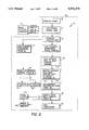
- FIG. 2 is a flow chart of a subarray interference suppressor routine for generating the phase shift and attenuation commands for each element of the phased array antenna;
- FIG. 3 is a block diagram of an eight-module controller embodying a subarray interference suppressor for suppressing wideband interference
- FIG. 4 is a perspective block diagram of a phased array radar antenna which includes the invention.
- FIG. 5 shows a graph of a narrowband notched pattern using a conventional algorithm of the prior art full-aperture interference suppressor at 20° array scan in elevation (designed to have -55 dB notch unit).
- FIG. 6 shows a graph of a degraded wideband notched pattern averaged over the full bandwidth at 20° array scan in elevation which results in accordance with the conventional algorithm of the prior art full-aperture interference suppressor;
- FIG. 7 shows a graph of a monopulse array pattern without notching for interference suppression comprising a Taylor sum beam and a Bayliss difference beam;
- FIG. 8 shows a graph of a prior art full-aperture notched monopulse array pattern having a difference beam that is significantly degraded
- FIG. 9 shows a graph of a wideband notched pattern averaged over the full bandwidth at 20° array scan in elevation which results in accordance with the invention of a subarray interference suppressor.
- FIG. 10 shows a graph of notched monopulse patterns with no null squinting of the difference beam resulting from the invention of a subarray interference suppressor.
- phased array radar system 10 having a monopulse phased array antenna 31 comprising a plurality of subarrays 27 1-72 with each subarray comprising 352 radiating elements 26 1-352 which are coupled to corresponding phase shifters 24 1-352 and attenuators 25 1-352 .
- the phase shifters 24 and attenuators 25 are controlled by eight-module controllers 20 1-40 whereby each eight-module controller 20 provides command words for eight phase shifters 24 and eight attenuators 25.
- Each eight-module controller 20 comprises the invention of a subarray interference suppressor 22 1-44 for providing sum channel notching and simultaneous difference channel notching without difference null degradation by applying complex weights (phase shift and attenuation) at the subarray level consistent with notching the desired angular coverage on the subarray patterns.
- the same or identical subarray notching weights of phase shift and attenuation for one subarray are applied to each of the 72 subarrays, and the outputs of all time-steering subarrays in the total array antenna 31 of the preferred embodiment shown in FIG. 4 are combined to produce a wideband notch in the direction of interference.
- the eight-module controller 20 is a processor for performing calculations required to provide the command words for the eight phase shifters 24 and attenuators 25.
- the phase shift command for each particular radiating element 26 of the phased array antenna 31 is based on the direction of phase-steered beam of electromagnetic energy and the radiating element 26 location in the array antenna 31 as well as the control of a spatial distribution of electromagnetic energy of the antenna 31 such as notching for suppressing interference.
- the attenuation command for each particular radiating element 26 of the phased array antenna is based on the control of a spatial distribution of electromagnetic energy of the antenna 31 such as notching for suppressing interference.
- a source of electromagnetic energy is provided to a transmit beamformer 11, and it is coupled to a subarray driver 12 for time-steering a direction of a corresponding beam of electromagnetic energy of the antenna 31 being transmitted and received by the subarray 27.
- Electromagnetic energy is distributed by a subarray combiner 14 through the phase shifters 24 for determining the direction of the energy beam 28 and through the attenuators 25 and phase shifters 24 for controlling spatial distribution of the energy beam 28 such as notching emitted from the phased array antenna 31.
- Radar return signals are provided to the subarray combiner 14 and then coupled to the subarray driver 12 for combining outputs of attenuators 25 and phase shifters 24 in each subarray 27 to produce a phase-steered beam emitted from the subarray 27 with an identical notch in the direction of interference for each subarray 27. They are then sent to the receive beamformer 16 for combining outputs of the subarray drivers 12, to produce a wideband steered beam emitted from the antenna with a wideband notch in the direction of the interference.
- An electronic unit 18 provides an exciter input 17 and timing and control signals for the complete radar phased array antenna system 10.
- a beam steering generator 19 performs the data processing of the radar data and performs built-in test (BITE) or self-test capability for aiding in diagnostics and fault isolation of the eight-module controllers 20.
- the beam steering generator 19 provides initialization data comprising algorithm constants to each of the eight-module controllers 20.
- Three serial control lines, clock 32, mode 34 and data 36, are coupled from the beam steering generator 19 to the eight-module controllers 20, and a serial BITE line is coupled from the eight-module controllers 19 to the beam steering generator 19.
- Three serial control lines enable the eight-module controllers 20 to be communicated with individually or all controllers 20 simultaneously.
- FIG. 2 is a flow chart of the present invention of a wideband interference 33 suppressor for generating the phase shift and attenuation command words for each radiating element 26 of the phased array subarrays 27.
- FIG. 3 is a block diagram of the eight-module controller 20 embodying the interference suppressor routine 40.
- the interference suppressor routine 40 operates on data received from the beam steering generator 19 which is stored in a RAM 72 of the eight-module controller 20.
- the interference suppressor routine 40 is also located in RAM 72, and the purpose of this routine is to generate the attenuation command words 49 and phase shift command words 58 in accordance with predetermined subarray weightings, the identical set of subarray weightings being applied to all subarrays 27.
- a clear signal is generated which clears all registers and the RAM 72 in the module controller 20.
- a load program control word is loaded into the eight-module controller 20 and stored in RAM 72.
- initialize constant data 46 operation occurs which loads constant data of the array geometry and element locations from the beam steering generator 19 into the RAM 72.
- a load subarray suppressing phase shift terms 48 occurs which provides a predetermined subarray element-level phase shift consistent with notching the desired angular coverage on the subarray pattern itself.
- a compute phase shift command word 50 operation is performed which performs the operation of load variable word of beam steering command 52, multiply variable word with constant data of element locations and add subarray suppressing phase terms 56.
- Eight computed phase shift command words ( ⁇ MN ) are then forwarded to eight phase shifters 24 in the subarrays 27.
- the initialize constant data 46 step also includes loading subarray suppressing attenuation terms 47 which provides a predetermined subarray element-level attenuation consistent with notching the desired angular coverage on the subarray pattern itself. These subarray suppressing attenuation terms are applied repeatedly to the elements of each subarray in the total array; such subarray suppressing attenuation terms are stored in RAM 72. Eight output attenuation command words 49 are then forwarded to eight of the attenuators 25 in the subarrays 27. The routine 40 proceeds with the computation in parallel of each eight antenna radiating elements 26 in the total array to complete these operations simultaneously.
- the eight-module controller 20 is implemented with 0.9 ⁇ CMOS technology at the Raytheon Company Microelectronic Center, in Andover, Mass. on a standard 275 mil square sea-of-gates die.
- Differential receivers 62 receive the differential forms of the three serial control signals clock 32, mode 34 and data 36 and provide these signals to a chip controller 64.
- the chip controller 64 converts the serial mode 34 and data 36 signals into parallel control words for use by other portions of the eight-module controller 20.
- a program control register 63 within the chip controller 64 stores a 20-bit program control word which determines the terms and variable word length used for a phase shift algorithm and defines the current BITE mode.
- a mode control register 66 stores the mode word received from the beam steering generator 19 and the mode word is decoded and used both in a direct form and in a pulsed form to provide required mode control.
- the random access memory (RAM) 72 receives data from the serial data 36 input under the control of the chip controller 64.
- the RAM 72 stores the constants for each element location, beam steering command data and the interference suppressor routine 40.
- the arithmetic unit 74 comprises eight arithmetic units, each arithmetic unit includes a 17-bit serial multiplier and serial adder (not shown but known to one skilled in the art) which forms partial product terms and subsequently a full product term.
- the product term size is that of a BAMS (Binary Angular Measurement System) variable.
- BAMS Binary Angular Measurement System
- the full product term is added to other accumulated terms of the phase-shift algorithm using the 17-bit serial adder within the arithmetic unit 74. Any negative constant term is taken care of by including a 2's compliment adjustment at the input to the serial adder.
- the final accumulated result is truncated to eight most significant fractional bits (MSBs) for parallel output to an output controller 76.
- MSBs most significant fractional bits
- a temperature correction (TC) factor for the phase shift algorithm may be generated from an ambient temperature measurement made by a thermal sensor and fed into the eight-module controller 20.
- the temperature correction (TC) factor would be fed to the serial adder input of the arithmetic unit 54 where it may be added into the sum of products in the beam steering calculation producing a phase output which has been corrected for temperature at the antenna element location.
- the eight MSBs of the phase-shift calculated in the arithmetic unit 74 are transferred to an output controller 76 where they are loaded into an 8-bit phase output register 82.
- a phase value can be loaded directly from the input data 36 line and then transferred to the phase output register 82.
- the output controller 76 comprises a 16-bit external control register which is loaded directly from the data 36 input and it is used to store external control words.
- Transmit (TRA) and receive (REC) control signals are derived from a decoded TRA/REC mode signal fed to a TRA/REC controls 78 in the output controller 76.
- the TRA and REC control signals are used to switch monolithic microwave integrated circuit (MMIC) devices and subsequently control the transmit/receive duty cycles.
- MMIC monolithic microwave integrated circuit
- the output controller 76 also comprises a built-in test (BITE) decoder 84.
- a BITE code (B 2 B 1 B 0 ) of the program control word is decoded and used to select one of four BITE return modes comprising data rebound BITE, external control BIT, parallel output BITE (PARBITE) and TRA/REC control BITE.
- BITE built-in test
- a BITE code (B 2 B 1 B 0 ) of the program control word is decoded and used to select one of four BITE return modes comprising data rebound BITE, external control BIT, parallel output BITE (PARBITE) and TRA/REC control BITE.
- PARBITE parallel output BITE
- TRA/REC control BITE TRA/REC control BITE.
- the external control BITE mode allows any data stored in the 16-bit external control register (ECR) 80 to be transferred serially to the BITE 38 line.
- any phase value stored in the phase output register 82 can be clocked-out serially onto the BITE 38 line by first transferring the 8-bit value to the eight least significant bit (LSB) positions of the external control register 80.
- the T/R control BITE mode verifies that the distributed controller 20 has been placed in the transmit mode or receive mode.
- the logic-OR of the transmit (TRA) or receive (REC) control signals is placed on the BITE 38 line for verification.
- the BITE 38 line is connected to a differential driver 86 for transferring BITE data to the beam steering generator 19.
- the beam steering generator 19 sets up each distributed controller 20 into the BITE mode and tests the data sent back over the BITE 38 line.
- FIG. 4 a perspective block diagram of the monopulse phased array radar antenna 31 which includes the invention is shown.
- the antenna 31 comprises seventy-two (72) subarrays 27 arranged in a 12 ⁇ 6 matrix, and each subarray 27 comprises 352 radiating elements 26 as shown in FIG. 1.
- a subarray combiner 14 for providing an azimuth difference beam ( ⁇ Az), an elevation difference beam ( ⁇ E1) and a sum beam ( ⁇ ) for precision tracking of monopulse operation.
- the subarray combiner 14 of a sum beam combines uniformly for each subarray the outputs of the elements with Taylor weightings to produce a Taylor-weighted sum beam for normal mode of antenna operation or notch weightings to produce a notched sum beam for an interference suppressor mode of antenna operation.
- the subarray combiners 14 of an azimuth difference (or elevation difference) beam uses a Bayliss/Taylor non-uniform combiner to combine the outputs of the elements with the same Taylor weightings to produce a Bayliss weighted difference beam for normal mode of antenna operation or notch weightings to produce a notched difference beam for interference suppression for each subarray.
- subarray drivers 12 which comprise a three section time delay unit (TDU) with time delay controls for ⁇ Az, ⁇ E1 and ⁇ for time-steering a direction of a corresponding beam of electromagnetic energy of the antenna for wideband monopulse operation.
- the subarray drivers 12 are coupled to three monopulse receive beamformer 16 and a transmit beamformer 11.
- Three monopulse receive beamformers combine uniformly the corresponding TDU outputs of seventy-two subarray drivers 12 to simultaneously form the azimuth difference beam, the elevation difference beam and the sum beam with a wideband notch in the direction of interference.
- the transmit beamformer 11 distributes uniformly seventy-two outputs to the subarray driver 12 for forming the uniformly weighted transmit beam for the maximum efficiency of a T/R module.
- the ⁇ Az, ⁇ E1 and ⁇ outputs from the receive beamformers 16 are coupled to the electron unit 18 for further processing, and exciter input 17 from the electronic unit 18 is fed to the transmit beamformer 11.
- exciter input 17 from the electronic unit 18 is fed to the transmit beamformer 11.
- FIG. 5 shows a graph of an array pattern without notching comprising a 30 dB Taylor sum beam and a 30 dB Bayliss difference beam. These beams result from the beamformers architecture shown in FIG. 4 without using the present invention of the subarray interference suppressor.
- FIG. 6 shows a graph of a full aperture notched monopulse array pattern having a difference beam that is significantly degraded as indicated by the 303 microradians of null squinting.
- FIG. 7 shows a graph of a wideband notched pattern using the present subarray interference suppressor invention averaged over the full bandwidth at 20° array scan in elevation.
- FIG. 8 shows a graph of notched monopulse patterns having a notched sum beam and a notched difference beam resulting from the phased array antenna 31 of FIG. 1 and FIG. 4 employing the present invention.
- the notched difference beam shows no null squinting.
- the generation of the predetermined attenuations and phase shifts for the elements of a phased array antenna 31 are well known in the art and described in the paper by H. J. Orchard, R. S. Elliott and G. J.
Abstract
Description
Claims (20)
Priority Applications (1)
| Application Number | Priority Date | Filing Date | Title |
|---|---|---|---|
| US08/252,502 US5592178A (en) | 1994-06-01 | 1994-06-01 | Wideband interference suppressor in a phased array radar |
Applications Claiming Priority (1)
| Application Number | Priority Date | Filing Date | Title |
|---|---|---|---|
| US08/252,502 US5592178A (en) | 1994-06-01 | 1994-06-01 | Wideband interference suppressor in a phased array radar |
Publications (1)
| Publication Number | Publication Date |
|---|---|
| US5592178A true US5592178A (en) | 1997-01-07 |
Family
ID=22956280
Family Applications (1)
| Application Number | Title | Priority Date | Filing Date |
|---|---|---|---|
| US08/252,502 Expired - Lifetime US5592178A (en) | 1994-06-01 | 1994-06-01 | Wideband interference suppressor in a phased array radar |
Country Status (1)
| Country | Link |
|---|---|
| US (1) | US5592178A (en) |
Cited By (93)
| Publication number | Priority date | Publication date | Assignee | Title |
|---|---|---|---|---|
| US5771016A (en) * | 1997-12-05 | 1998-06-23 | The United States Of America As Represented By The Secretary Of The Army | Phased array radar with simultaneous beam-steering and single-sideband modulation |
| US5867123A (en) * | 1997-06-19 | 1999-02-02 | Motorola, Inc. | Phased array radio frequency (RF) built-in-test equipment (BITE) apparatus and method of operation therefor |
| US5923289A (en) * | 1997-07-28 | 1999-07-13 | Motorola, Inc. | Modular array and phased array antenna system |
| US6100843A (en) * | 1998-09-21 | 2000-08-08 | Tantivy Communications Inc. | Adaptive antenna for use in same frequency networks |
| US20010036200A1 (en) * | 2000-02-07 | 2001-11-01 | Tantivy Communications, Inc. | Minimal maintenance link to support synchronization |
| US6404386B1 (en) | 1998-09-21 | 2002-06-11 | Tantivy Communications, Inc. | Adaptive antenna for use in same frequency networks |
| WO2002050942A2 (en) * | 2000-12-21 | 2002-06-27 | Henderson John G N | Steerable antenna and receiver interface for broadcast |
| US20020080742A1 (en) * | 1997-12-17 | 2002-06-27 | Tantivy Communications, Inc. | System and method for maintaining timing of synchronization messages over a reverse link of a CDMA wireless communication system |
| US6496143B1 (en) * | 2001-11-09 | 2002-12-17 | Harris Corporation | Phased array antenna including a multi-mode element controller and related method |
| EP1267444A2 (en) * | 2001-06-15 | 2002-12-18 | Lockheed Martin Corporation | Adaptive digital sub-array beamforming and deterministic sum and difference beamforming with jamming cancellation and monopulse ratio preservation |
| EP1286180A2 (en) * | 2001-08-16 | 2003-02-26 | Lockheed Martin Corporation | Periodic repetition interval staggered post-doppler adaptive monopulse processing for detection and location of a moving target in ground clutter |
| US6529166B2 (en) | 2000-09-22 | 2003-03-04 | Sarnoff Corporation | Ultra-wideband multi-beam adaptive antenna |
| US6529162B2 (en) * | 2001-05-17 | 2003-03-04 | Irwin L. Newberg | Phased array antenna system with virtual time delay beam steering |
| US6710739B1 (en) | 2003-01-03 | 2004-03-23 | Northrop Grumman Corporation | Dual redundant GPS anti-jam air vehicle navigation system architecture and method |
| EP1423726A2 (en) * | 2001-09-07 | 2004-06-02 | Lockheed Martin Corporation | Adaptive digital beamforming radar method and system for maintaining multiple source angle super-resolution capability in jamming |
| US20050013284A1 (en) * | 1998-06-01 | 2005-01-20 | Tantivy Communications, Inc. | System and method for maintaining timing of synchronization messages over a reverse link of a CDMA wireless communication system |
| US20050030222A1 (en) * | 2003-07-25 | 2005-02-10 | Fritz Steudel | Process for phase-derived range measurements |
| US6868044B1 (en) * | 2003-01-29 | 2005-03-15 | Lockheed Martin Corporation | Data adaptive interference suppression |
| US20050068231A1 (en) * | 1998-09-21 | 2005-03-31 | Ipr Licensing, Inc. | Method and apparatus for adapting antenna array using received perdetermined signal |
| US20050231420A1 (en) * | 2003-10-10 | 2005-10-20 | Eli Brookner | Multiple radar combining for increased range, radar sensitivity and angle accuracy |
| US20050249168A1 (en) * | 1998-06-01 | 2005-11-10 | Tantivy Communications, Inc. | System and method for maintaining wireless channels over a reverse link of a CDMA wireless communication system |
| US20050253748A1 (en) * | 2003-10-10 | 2005-11-17 | Eli Brookner | Efficient technique for estimating elevation angle when using a broad beam for search in a radar |
| US20050285785A1 (en) * | 2004-06-10 | 2005-12-29 | Harris Corporation, Corporation Of The State Of Delaware | Communications system including phased array antenna providing nulling and related methods |
| US20060125682A1 (en) * | 2004-12-15 | 2006-06-15 | Kelly Thomas M Jr | System and method for reducing a radar interference signal |
| US20060145778A1 (en) * | 2004-12-30 | 2006-07-06 | Pleva Joseph S | Waveguide - printed wiring board (PWB) interconnection |
| US20060145919A1 (en) * | 2004-12-30 | 2006-07-06 | Pleva Joseph S | Beam architecture for improving angular resolution |
| US20060152406A1 (en) * | 2004-12-30 | 2006-07-13 | Leblanc Stephen P | Vehicle radar sensor assembly |
| US20060274711A1 (en) * | 2000-02-07 | 2006-12-07 | Nelson G R Jr | Maintenance link using active/standby request channels |
| US20070120731A1 (en) * | 2004-12-15 | 2007-05-31 | Kelly Thomas M Jr | System and method for reducing the effect of a radar interference signal |
| US20070152870A1 (en) * | 2005-12-30 | 2007-07-05 | Woodington Walter G | Vehicle radar system having multiple operating modes |
| US20070152872A1 (en) * | 2005-12-30 | 2007-07-05 | Woodington Walter G | Reducing undesirable coupling of signal(s) between two or more signal paths in a radar system |
| US20070156799A1 (en) * | 2005-12-30 | 2007-07-05 | Gilbert Michael J | Multi-stage finite impulse response filter processing |
| US20070152869A1 (en) * | 2005-12-30 | 2007-07-05 | Woodington Walter G | Multichannel processing of signals in a radar system |
| US20070152874A1 (en) * | 2005-12-30 | 2007-07-05 | Woodington Walter G | Reducing undesirable coupling of signal(s) between two or more signal paths in a radar system |
| US20070152873A1 (en) * | 2005-12-30 | 2007-07-05 | Valeo Raytheon Systems, Inc. | Generating event signals in a radar system |
| US20070210977A1 (en) * | 1998-09-21 | 2007-09-13 | Ipr Licensing, Inc. | Adaptive antenna for use in wireless communication systems |
| US20070223426A1 (en) * | 1998-06-01 | 2007-09-27 | Tantivy Communications, Inc. | Transmittal of heartbeat signal at a lower lever than heartbeat request |
| US20080001809A1 (en) * | 2006-06-30 | 2008-01-03 | Walter Gordon Woodington | Detecting signal interference in a vehicle system |
| US7336219B1 (en) | 2005-12-30 | 2008-02-26 | Valeo Raytheon Systems, Inc. | System and method for generating a radar detection threshold |
| US7379018B1 (en) | 2005-12-30 | 2008-05-27 | Valeo Raytheon Systems, Inc. | System and method for verifying a radar detection |
| US20090086680A1 (en) * | 1997-12-17 | 2009-04-02 | Tantivy Communications, Inc. | Multi-detection of heartbeat to reduce error probability |
| US20090175249A1 (en) * | 2001-02-01 | 2009-07-09 | Ipr Licensing, Inc. | Alternate channel for carrying selected message types |
| US20090201214A1 (en) * | 2008-02-07 | 2009-08-13 | Saab Abse-581 | Wideband antenna pattern |
| US20090231195A1 (en) * | 2008-03-12 | 2009-09-17 | Kaichiang Chang | Adaptive processing method of clutter rejection in a phased array beam pattern |
| US20090257479A1 (en) * | 2001-02-01 | 2009-10-15 | Ipr Licensing, Inc. | Use of correlation combination to achieve channel detection |
| US20090256749A1 (en) * | 2008-02-07 | 2009-10-15 | Saab Abse-581 | Side lobe suppression |
| US20100238066A1 (en) * | 2005-12-30 | 2010-09-23 | Valeo Raytheon Systems, Inc. | Method and system for generating a target alert |
| US7843380B1 (en) * | 2007-09-27 | 2010-11-30 | Rockwell Collins, Inc. | Half aperture antenna resolution system and method |
| WO2011008146A1 (en) * | 2009-07-16 | 2011-01-20 | Saab Ab | Method and wideband antenna system to minimise the influence of interference sources |
| US8144051B2 (en) | 2008-09-05 | 2012-03-27 | Raytheon Company | Adaptive sidelobe blanking for motion compensation |
| US8155096B1 (en) | 2000-12-01 | 2012-04-10 | Ipr Licensing Inc. | Antenna control system and method |
| US8384588B2 (en) | 2010-10-26 | 2013-02-26 | Raytheon Company | Beam stabilization for wideband phase comparison monopulse angle estimation with electronically steered antennas |
| US20130088381A1 (en) * | 2011-10-06 | 2013-04-11 | Raytheon Company | Scalable, analog monopulse network |
| US8451173B2 (en) | 2011-04-21 | 2013-05-28 | Raytheon Company | Maximum likelihood angle estimation of wideband signals using phased array antennas |
| WO2013106806A1 (en) * | 2012-01-12 | 2013-07-18 | Booz, Allen & Hamilton | Radio-frequency (rf) precision nulling device |
| US8526550B1 (en) | 2009-03-18 | 2013-09-03 | Lockheed Martin Corporation | System and method for wideband interference suppression |
| US8558731B1 (en) | 2008-07-02 | 2013-10-15 | Rockwell Collins, Inc. | System for and method of sequential lobing using less than full aperture antenna techniques |
| US8604976B1 (en) | 2011-08-25 | 2013-12-10 | Raytheon Company | Broad beam antenna design for a tilted phased array with platform motion |
| US8698669B1 (en) | 2008-07-25 | 2014-04-15 | Rockwell Collins, Inc. | System and method for aircraft altitude measurement using radar and known runway position |
| US8908654B2 (en) | 1998-06-01 | 2014-12-09 | Intel Corporation | Dynamic bandwidth allocation for multiple access communications using buffer urgency factor |
| US9014118B2 (en) | 2001-06-13 | 2015-04-21 | Intel Corporation | Signaling for wireless communications |
| US9019145B1 (en) | 2011-07-14 | 2015-04-28 | Rockwell Collins, Inc. | Ground clutter rejection for weather radar |
| US20150236413A1 (en) * | 2014-02-14 | 2015-08-20 | The Boeing Company | Adaptive interference suppression via subband power measurements of a phased-array antenna |
| US9184498B2 (en) | 2013-03-15 | 2015-11-10 | Gigoptix, Inc. | Extending beamforming capability of a coupled voltage controlled oscillator (VCO) array during local oscillator (LO) signal generation through fine control of a tunable frequency of a tank circuit of a VCO thereof |
| US9275690B2 (en) | 2012-05-30 | 2016-03-01 | Tahoe Rf Semiconductor, Inc. | Power management in an electronic system through reducing energy usage of a battery and/or controlling an output power of an amplifier thereof |
| US9325075B1 (en) | 2012-05-25 | 2016-04-26 | Lockheed Martin Corporation | Antennae formed using integrated subarrays |
| US9354633B1 (en) | 2008-10-31 | 2016-05-31 | Rockwell Collins, Inc. | System and method for ground navigation |
| US9384586B1 (en) | 2013-04-05 | 2016-07-05 | Rockwell Collins, Inc. | Enhanced flight vision system and method with radar sensing and pilot monitoring display |
| US9408216B2 (en) | 1997-06-20 | 2016-08-02 | Intel Corporation | Dynamic bandwidth allocation to transmit a wireless protocol across a code division multiple access (CDMA) radio link |
| US20160277084A1 (en) * | 2007-08-02 | 2016-09-22 | Nec Corporation | Mimo communication system having deterministic communication path and antenna arrangement method therfor |
| US9509351B2 (en) | 2012-07-27 | 2016-11-29 | Tahoe Rf Semiconductor, Inc. | Simultaneous accommodation of a low power signal and an interfering signal in a radio frequency (RF) receiver |
| US9525923B2 (en) | 1997-12-17 | 2016-12-20 | Intel Corporation | Multi-detection of heartbeat to reduce error probability |
| US9531070B2 (en) | 2013-03-15 | 2016-12-27 | Christopher T. Schiller | Extending beamforming capability of a coupled voltage controlled oscillator (VCO) array during local oscillator (LO) signal generation through accommodating differential coupling between VCOs thereof |
| US20170040710A1 (en) * | 2015-08-09 | 2017-02-09 | The United States Of America As Represented By The Secretary Of The Navy | System including a hybrid active array |
| US9653796B2 (en) | 2013-12-16 | 2017-05-16 | Valeo Radar Systems, Inc. | Structure and technique for antenna decoupling in a vehicle mounted sensor |
| US9666942B2 (en) | 2013-03-15 | 2017-05-30 | Gigpeak, Inc. | Adaptive transmit array for beam-steering |
| US9716315B2 (en) | 2013-03-15 | 2017-07-25 | Gigpeak, Inc. | Automatic high-resolution adaptive beam-steering |
| US9722310B2 (en) | 2013-03-15 | 2017-08-01 | Gigpeak, Inc. | Extending beamforming capability of a coupled voltage controlled oscillator (VCO) array during local oscillator (LO) signal generation through frequency multiplication |
| US9733349B1 (en) | 2007-09-06 | 2017-08-15 | Rockwell Collins, Inc. | System for and method of radar data processing for low visibility landing applications |
| US9780449B2 (en) | 2013-03-15 | 2017-10-03 | Integrated Device Technology, Inc. | Phase shift based improved reference input frequency signal injection into a coupled voltage controlled oscillator (VCO) array during local oscillator (LO) signal generation to reduce a phase-steering requirement during beamforming |
| US9837714B2 (en) | 2013-03-15 | 2017-12-05 | Integrated Device Technology, Inc. | Extending beamforming capability of a coupled voltage controlled oscillator (VCO) array during local oscillator (LO) signal generation through a circular configuration thereof |
| US9939526B2 (en) | 2007-09-06 | 2018-04-10 | Rockwell Collins, Inc. | Display system and method using weather radar sensing |
| US10228460B1 (en) | 2016-05-26 | 2019-03-12 | Rockwell Collins, Inc. | Weather radar enabled low visibility operation system and method |
| US10353068B1 (en) | 2016-07-28 | 2019-07-16 | Rockwell Collins, Inc. | Weather radar enabled offshore operation system and method |
| US10594031B1 (en) * | 2017-09-06 | 2020-03-17 | Rockwell Collins, Inc. | Radio frequency integrated circuit feed manifold for active electronically scanned array |
| US10705201B1 (en) | 2015-08-31 | 2020-07-07 | Rockwell Collins, Inc. | Radar beam sharpening system and method |
| US10928510B1 (en) | 2014-09-10 | 2021-02-23 | Rockwell Collins, Inc. | System for and method of image processing for low visibility landing applications |
| US11271613B2 (en) * | 2011-08-17 | 2022-03-08 | Skyline Partners Technology Llc | Radio with spatially-offset directional antenna sub-arrays |
| US11283192B2 (en) | 2011-08-17 | 2022-03-22 | Skyline Partners Technology Llc | Aperture-fed, stacked-patch antenna assembly |
| US11303322B2 (en) | 2013-12-05 | 2022-04-12 | Skyline Partners Technology Llc | Advanced backhaul services |
| US20220146657A1 (en) * | 2020-11-12 | 2022-05-12 | Thales | Multiple-input multiple-output imaging radar system |
| US11343684B2 (en) | 2011-08-17 | 2022-05-24 | Skyline Partners Technology Llc | Self organizing backhaul radio |
| RU2802177C1 (en) * | 2023-04-06 | 2023-08-22 | Федеральное Государственное Бюджетное Образовательное Учреждение Высшего Образования "Новосибирский Государственный Технический Университет" | Vibrator antenna system |
Citations (10)
| Publication number | Priority date | Publication date | Assignee | Title |
|---|---|---|---|---|
| US3763490A (en) * | 1971-12-10 | 1973-10-02 | Gen Electric | Adaptive beamformer with time constant control |
| US4017867A (en) * | 1976-02-25 | 1977-04-12 | Bell Telephone Laboratories, Incorporated | Antenna assembly producing steerable beam and null |
| US4336543A (en) * | 1977-05-18 | 1982-06-22 | Grumman Corporation | Electronically scanned aircraft antenna system having a linear array of yagi elements |
| US4489324A (en) * | 1982-11-30 | 1984-12-18 | Blume Alan E | Low sidelobe phased array antenna system |
| US4495502A (en) * | 1982-01-27 | 1985-01-22 | The United States Of America As Represented By The Secretary Of The Air Force | Multiple loop sidelobe canceller |
| US4516126A (en) * | 1982-09-30 | 1985-05-07 | Hazeltine Corporation | Adaptive array having an auxiliary channel notched pattern in the steered beam direction |
| US4736460A (en) * | 1986-11-10 | 1988-04-05 | Kenneth Rilling | Multipath reduction system |
| US4872016A (en) * | 1988-09-06 | 1989-10-03 | Grumman Aerospace Corporation | Data processing system for a phased array antenna |
| US4937584A (en) * | 1988-12-22 | 1990-06-26 | United States Of America As Represented By The Secretary Of The Navy | Adaptive phase-shifter nulling techniques for large-aperture phases arrays |
| US5103232A (en) * | 1991-04-18 | 1992-04-07 | Raytheon Company | Phase quantization error decorrelator for phased array antenna |
-
1994
- 1994-06-01 US US08/252,502 patent/US5592178A/en not_active Expired - Lifetime
Patent Citations (10)
| Publication number | Priority date | Publication date | Assignee | Title |
|---|---|---|---|---|
| US3763490A (en) * | 1971-12-10 | 1973-10-02 | Gen Electric | Adaptive beamformer with time constant control |
| US4017867A (en) * | 1976-02-25 | 1977-04-12 | Bell Telephone Laboratories, Incorporated | Antenna assembly producing steerable beam and null |
| US4336543A (en) * | 1977-05-18 | 1982-06-22 | Grumman Corporation | Electronically scanned aircraft antenna system having a linear array of yagi elements |
| US4495502A (en) * | 1982-01-27 | 1985-01-22 | The United States Of America As Represented By The Secretary Of The Air Force | Multiple loop sidelobe canceller |
| US4516126A (en) * | 1982-09-30 | 1985-05-07 | Hazeltine Corporation | Adaptive array having an auxiliary channel notched pattern in the steered beam direction |
| US4489324A (en) * | 1982-11-30 | 1984-12-18 | Blume Alan E | Low sidelobe phased array antenna system |
| US4736460A (en) * | 1986-11-10 | 1988-04-05 | Kenneth Rilling | Multipath reduction system |
| US4872016A (en) * | 1988-09-06 | 1989-10-03 | Grumman Aerospace Corporation | Data processing system for a phased array antenna |
| US4937584A (en) * | 1988-12-22 | 1990-06-26 | United States Of America As Represented By The Secretary Of The Navy | Adaptive phase-shifter nulling techniques for large-aperture phases arrays |
| US5103232A (en) * | 1991-04-18 | 1992-04-07 | Raytheon Company | Phase quantization error decorrelator for phased array antenna |
Non-Patent Citations (4)
| Title |
|---|
| "Optimizing the Synthesis of Shaped Beam Antenna Patterns," H. J. Orchard, R. S. Elliott, G. J. Stern, IEEE Proceedings (London), Pt. H., 1 (1985), pp. 63-68. |
| "Pattern Synthesis Based on Adaptive Array Theory," E. C. Dufort, IEEE Transactions on Antennas and Propagation, vol. 37, No. 8, Aug. 1989, pp. 1011-1018. |
| Optimizing the Synthesis of Shaped Beam Antenna Patterns, H. J. Orchard, R. S. Elliott, G. J. Stern, IEEE Proceedings (London), Pt. H., 1 (1985), pp. 63 68. * |
| Pattern Synthesis Based on Adaptive Array Theory, E. C. Dufort, IEEE Transactions on Antennas and Propagation, vol. 37, No. 8, Aug. 1989, pp. 1011 1018. * |
Cited By (154)
| Publication number | Priority date | Publication date | Assignee | Title |
|---|---|---|---|---|
| US5867123A (en) * | 1997-06-19 | 1999-02-02 | Motorola, Inc. | Phased array radio frequency (RF) built-in-test equipment (BITE) apparatus and method of operation therefor |
| US9408216B2 (en) | 1997-06-20 | 2016-08-02 | Intel Corporation | Dynamic bandwidth allocation to transmit a wireless protocol across a code division multiple access (CDMA) radio link |
| US5923289A (en) * | 1997-07-28 | 1999-07-13 | Motorola, Inc. | Modular array and phased array antenna system |
| US5771016A (en) * | 1997-12-05 | 1998-06-23 | The United States Of America As Represented By The Secretary Of The Army | Phased array radar with simultaneous beam-steering and single-sideband modulation |
| US20020080742A1 (en) * | 1997-12-17 | 2002-06-27 | Tantivy Communications, Inc. | System and method for maintaining timing of synchronization messages over a reverse link of a CDMA wireless communication system |
| US9525923B2 (en) | 1997-12-17 | 2016-12-20 | Intel Corporation | Multi-detection of heartbeat to reduce error probability |
| US9042400B2 (en) | 1997-12-17 | 2015-05-26 | Intel Corporation | Multi-detection of heartbeat to reduce error probability |
| US7936728B2 (en) | 1997-12-17 | 2011-05-03 | Tantivy Communications, Inc. | System and method for maintaining timing of synchronization messages over a reverse link of a CDMA wireless communication system |
| US20090086680A1 (en) * | 1997-12-17 | 2009-04-02 | Tantivy Communications, Inc. | Multi-detection of heartbeat to reduce error probability |
| US8908654B2 (en) | 1998-06-01 | 2014-12-09 | Intel Corporation | Dynamic bandwidth allocation for multiple access communications using buffer urgency factor |
| US20050013284A1 (en) * | 1998-06-01 | 2005-01-20 | Tantivy Communications, Inc. | System and method for maintaining timing of synchronization messages over a reverse link of a CDMA wireless communication system |
| US8134980B2 (en) | 1998-06-01 | 2012-03-13 | Ipr Licensing, Inc. | Transmittal of heartbeat signal at a lower level than heartbeat request |
| US20070223426A1 (en) * | 1998-06-01 | 2007-09-27 | Tantivy Communications, Inc. | Transmittal of heartbeat signal at a lower lever than heartbeat request |
| US20100208708A1 (en) * | 1998-06-01 | 2010-08-19 | Tantivy Communications, Inc. | System and method for maintaining wireless channels over a reverse link of a cdma wireless communication system |
| US9307532B2 (en) | 1998-06-01 | 2016-04-05 | Intel Corporation | Signaling for wireless communications |
| US8792458B2 (en) | 1998-06-01 | 2014-07-29 | Intel Corporation | System and method for maintaining wireless channels over a reverse link of a CDMA wireless communication system |
| US7773566B2 (en) | 1998-06-01 | 2010-08-10 | Tantivy Communications, Inc. | System and method for maintaining timing of synchronization messages over a reverse link of a CDMA wireless communication system |
| US7746830B2 (en) | 1998-06-01 | 2010-06-29 | Interdigital Technology Corporation | System and method for maintaining wireless channels over a reverse link of a CDMA wireless communication system |
| US8139546B2 (en) | 1998-06-01 | 2012-03-20 | Ipr Licensing, Inc. | System and method for maintaining wireless channels over a reverse link of a CDMA wireless communication system |
| US20050249168A1 (en) * | 1998-06-01 | 2005-11-10 | Tantivy Communications, Inc. | System and method for maintaining wireless channels over a reverse link of a CDMA wireless communication system |
| US20050068231A1 (en) * | 1998-09-21 | 2005-03-31 | Ipr Licensing, Inc. | Method and apparatus for adapting antenna array using received perdetermined signal |
| US6304215B1 (en) | 1998-09-21 | 2001-10-16 | Tantivy Communications, Inc. | Method of use for an adaptive antenna in same frequency networks |
| US20070210977A1 (en) * | 1998-09-21 | 2007-09-13 | Ipr Licensing, Inc. | Adaptive antenna for use in wireless communication systems |
| US6518920B2 (en) * | 1998-09-21 | 2003-02-11 | Tantivy Communications, Inc. | Adaptive antenna for use in same frequency networks |
| US6404386B1 (en) | 1998-09-21 | 2002-06-11 | Tantivy Communications, Inc. | Adaptive antenna for use in same frequency networks |
| US7528789B2 (en) | 1998-09-21 | 2009-05-05 | Ipr Licensing, Inc. | Adaptive antenna for use in wireless communication systems |
| US6100843A (en) * | 1998-09-21 | 2000-08-08 | Tantivy Communications Inc. | Adaptive antenna for use in same frequency networks |
| US7009559B2 (en) | 1998-09-21 | 2006-03-07 | Ipr Licensing, Inc. | Method and apparatus for adapting antenna array using received predetermined signal |
| US9301274B2 (en) | 2000-02-07 | 2016-03-29 | Intel Corporation | Minimal maintenance link to support synchronization |
| US8175120B2 (en) | 2000-02-07 | 2012-05-08 | Ipr Licensing, Inc. | Minimal maintenance link to support synchronization |
| US9807714B2 (en) | 2000-02-07 | 2017-10-31 | Intel Corporation | Minimal maintenance link to support synchronization |
| US8509268B2 (en) | 2000-02-07 | 2013-08-13 | Intel Corporation | Minimal maintenance link to support sychronization |
| US20060274711A1 (en) * | 2000-02-07 | 2006-12-07 | Nelson G R Jr | Maintenance link using active/standby request channels |
| US20010036200A1 (en) * | 2000-02-07 | 2001-11-01 | Tantivy Communications, Inc. | Minimal maintenance link to support synchronization |
| US6529166B2 (en) | 2000-09-22 | 2003-03-04 | Sarnoff Corporation | Ultra-wideband multi-beam adaptive antenna |
| US9775115B2 (en) | 2000-12-01 | 2017-09-26 | Intel Corporation | Antenna control system and method |
| US9225395B2 (en) | 2000-12-01 | 2015-12-29 | Intel Corporation | Antenna control system and method |
| US8155096B1 (en) | 2000-12-01 | 2012-04-10 | Ipr Licensing Inc. | Antenna control system and method |
| US8437330B2 (en) | 2000-12-01 | 2013-05-07 | Intel Corporation | Antenna control system and method |
| US9924468B2 (en) | 2000-12-01 | 2018-03-20 | Intel Corporation | Antenna control system and method |
| US7425920B2 (en) | 2000-12-21 | 2008-09-16 | Hitachi America, Ltd. | Steerable antenna and receiver interface for terrestrial broadcast |
| US20060145918A1 (en) * | 2000-12-21 | 2006-07-06 | Henderson John G | Steerable antenna and receiver interface for terrestrial broadcast |
| US7006040B2 (en) | 2000-12-21 | 2006-02-28 | Hitachi America, Ltd. | Steerable antenna and receiver interface for terrestrial broadcast |
| WO2002050942A2 (en) * | 2000-12-21 | 2002-06-27 | Henderson John G N | Steerable antenna and receiver interface for broadcast |
| US8125386B2 (en) | 2000-12-21 | 2012-02-28 | Hitachi America, Ltd. | Steerable antenna and receiver interface for terrestrial broadcast |
| US20020083458A1 (en) * | 2000-12-21 | 2002-06-27 | Henderson John G. N. | Steerable antenna and receiver interface for terrestrial broadcast |
| WO2002050942A3 (en) * | 2000-12-21 | 2003-02-27 | John G N Henderson | Steerable antenna and receiver interface for broadcast |
| US8687606B2 (en) | 2001-02-01 | 2014-04-01 | Intel Corporation | Alternate channel for carrying selected message types |
| US8638877B2 (en) | 2001-02-01 | 2014-01-28 | Intel Corporation | Methods, apparatuses and systems for selective transmission of traffic data using orthogonal sequences |
| US9247510B2 (en) | 2001-02-01 | 2016-01-26 | Intel Corporation | Use of correlation combination to achieve channel detection |
| US20090257479A1 (en) * | 2001-02-01 | 2009-10-15 | Ipr Licensing, Inc. | Use of correlation combination to achieve channel detection |
| US8274954B2 (en) | 2001-02-01 | 2012-09-25 | Ipr Licensing, Inc. | Alternate channel for carrying selected message types |
| US20090175249A1 (en) * | 2001-02-01 | 2009-07-09 | Ipr Licensing, Inc. | Alternate channel for carrying selected message types |
| US6529162B2 (en) * | 2001-05-17 | 2003-03-04 | Irwin L. Newberg | Phased array antenna system with virtual time delay beam steering |
| US9014118B2 (en) | 2001-06-13 | 2015-04-21 | Intel Corporation | Signaling for wireless communications |
| EP1267444A3 (en) * | 2001-06-15 | 2004-03-31 | Lockheed Martin Corporation | Adaptive digital sub-array beamforming and deterministic sum and difference beamforming with jamming cancellation and monopulse ratio preservation |
| EP1267444A2 (en) * | 2001-06-15 | 2002-12-18 | Lockheed Martin Corporation | Adaptive digital sub-array beamforming and deterministic sum and difference beamforming with jamming cancellation and monopulse ratio preservation |
| US6661366B2 (en) * | 2001-06-15 | 2003-12-09 | Lockheed Martin Corporation | Adaptive digital sub-array beamforming and deterministic sum and difference beamforming, with jamming cancellation and monopulse ratio preservation |
| EP1286180A2 (en) * | 2001-08-16 | 2003-02-26 | Lockheed Martin Corporation | Periodic repetition interval staggered post-doppler adaptive monopulse processing for detection and location of a moving target in ground clutter |
| EP1286180A3 (en) * | 2001-08-16 | 2005-04-06 | Lockheed Martin Corporation | Periodic repetition interval staggered post-doppler adaptive monopulse processing for detection and location of a moving target in ground clutter |
| EP1423726A2 (en) * | 2001-09-07 | 2004-06-02 | Lockheed Martin Corporation | Adaptive digital beamforming radar method and system for maintaining multiple source angle super-resolution capability in jamming |
| EP1423726A4 (en) * | 2001-09-07 | 2008-11-05 | Lockheed Corp | Adaptive digital beamforming radar method and system for maintaining multiple source angle super-resolution capability in jamming |
| US6496143B1 (en) * | 2001-11-09 | 2002-12-17 | Harris Corporation | Phased array antenna including a multi-mode element controller and related method |
| US6710739B1 (en) | 2003-01-03 | 2004-03-23 | Northrop Grumman Corporation | Dual redundant GPS anti-jam air vehicle navigation system architecture and method |
| US6868044B1 (en) * | 2003-01-29 | 2005-03-15 | Lockheed Martin Corporation | Data adaptive interference suppression |
| US20050030222A1 (en) * | 2003-07-25 | 2005-02-10 | Fritz Steudel | Process for phase-derived range measurements |
| US7046190B2 (en) | 2003-07-25 | 2006-05-16 | Raytheon Company | Process for phase-derived range measurements |
| US20050231420A1 (en) * | 2003-10-10 | 2005-10-20 | Eli Brookner | Multiple radar combining for increased range, radar sensitivity and angle accuracy |
| US20050253748A1 (en) * | 2003-10-10 | 2005-11-17 | Eli Brookner | Efficient technique for estimating elevation angle when using a broad beam for search in a radar |
| US7038615B2 (en) | 2003-10-10 | 2006-05-02 | Raytheon Company | Efficient technique for estimating elevation angle when using a broad beam for search in a radar |
| US6977610B2 (en) | 2003-10-10 | 2005-12-20 | Raytheon Company | Multiple radar combining for increased range, radar sensitivity and angle accuracy |
| US7068219B2 (en) * | 2004-06-10 | 2006-06-27 | Harris Corporation | Communications system including phased array antenna providing nulling and related methods |
| US20050285785A1 (en) * | 2004-06-10 | 2005-12-29 | Harris Corporation, Corporation Of The State Of Delaware | Communications system including phased array antenna providing nulling and related methods |
| US7683827B2 (en) | 2004-12-15 | 2010-03-23 | Valeo Radar Systems, Inc. | System and method for reducing the effect of a radar interference signal |
| US20070120731A1 (en) * | 2004-12-15 | 2007-05-31 | Kelly Thomas M Jr | System and method for reducing the effect of a radar interference signal |
| US20060125682A1 (en) * | 2004-12-15 | 2006-06-15 | Kelly Thomas M Jr | System and method for reducing a radar interference signal |
| US7403153B2 (en) | 2004-12-15 | 2008-07-22 | Valeo Raytheon Systems, Inc. | System and method for reducing a radar interference signal |
| US20060145778A1 (en) * | 2004-12-30 | 2006-07-06 | Pleva Joseph S | Waveguide - printed wiring board (PWB) interconnection |
| US7680464B2 (en) | 2004-12-30 | 2010-03-16 | Valeo Radar Systems, Inc. | Waveguide—printed wiring board (PWB) interconnection |
| US20060145919A1 (en) * | 2004-12-30 | 2006-07-06 | Pleva Joseph S | Beam architecture for improving angular resolution |
| US20060152406A1 (en) * | 2004-12-30 | 2006-07-13 | Leblanc Stephen P | Vehicle radar sensor assembly |
| US7248215B2 (en) * | 2004-12-30 | 2007-07-24 | Valeo Raytheon Systems, Inc | Beam architecture for improving angular resolution |
| US7881689B2 (en) | 2004-12-30 | 2011-02-01 | Valeo Radar Systems, Inc. | Vehicle radar sensor assembly |
| US20090135043A1 (en) * | 2004-12-30 | 2009-05-28 | Leblanc Stephen P | Vehicle Radar Sensor Assembly |
| US7603097B2 (en) | 2004-12-30 | 2009-10-13 | Valeo Radar Systems, Inc. | Vehicle radar sensor assembly |
| US20100238066A1 (en) * | 2005-12-30 | 2010-09-23 | Valeo Raytheon Systems, Inc. | Method and system for generating a target alert |
| US20070156799A1 (en) * | 2005-12-30 | 2007-07-05 | Gilbert Michael J | Multi-stage finite impulse response filter processing |
| US20070152872A1 (en) * | 2005-12-30 | 2007-07-05 | Woodington Walter G | Reducing undesirable coupling of signal(s) between two or more signal paths in a radar system |
| US20070152869A1 (en) * | 2005-12-30 | 2007-07-05 | Woodington Walter G | Multichannel processing of signals in a radar system |
| US20070152874A1 (en) * | 2005-12-30 | 2007-07-05 | Woodington Walter G | Reducing undesirable coupling of signal(s) between two or more signal paths in a radar system |
| US20070152873A1 (en) * | 2005-12-30 | 2007-07-05 | Valeo Raytheon Systems, Inc. | Generating event signals in a radar system |
| US20070152870A1 (en) * | 2005-12-30 | 2007-07-05 | Woodington Walter G | Vehicle radar system having multiple operating modes |
| US7336219B1 (en) | 2005-12-30 | 2008-02-26 | Valeo Raytheon Systems, Inc. | System and method for generating a radar detection threshold |
| US7345619B2 (en) | 2005-12-30 | 2008-03-18 | Valeo Raytheon Systems, Inc. | Generating event signals in a radar system |
| US7379018B1 (en) | 2005-12-30 | 2008-05-27 | Valeo Raytheon Systems, Inc. | System and method for verifying a radar detection |
| US7400290B2 (en) | 2005-12-30 | 2008-07-15 | Valeo Raytheon Systems, Inc. | Vehicle radar system having multiple operating modes |
| US20080001809A1 (en) * | 2006-06-30 | 2008-01-03 | Walter Gordon Woodington | Detecting signal interference in a vehicle system |
| US20160277084A1 (en) * | 2007-08-02 | 2016-09-22 | Nec Corporation | Mimo communication system having deterministic communication path and antenna arrangement method therfor |
| US9733349B1 (en) | 2007-09-06 | 2017-08-15 | Rockwell Collins, Inc. | System for and method of radar data processing for low visibility landing applications |
| US9939526B2 (en) | 2007-09-06 | 2018-04-10 | Rockwell Collins, Inc. | Display system and method using weather radar sensing |
| US7843380B1 (en) * | 2007-09-27 | 2010-11-30 | Rockwell Collins, Inc. | Half aperture antenna resolution system and method |
| US20090201214A1 (en) * | 2008-02-07 | 2009-08-13 | Saab Abse-581 | Wideband antenna pattern |
| US8115679B2 (en) | 2008-02-07 | 2012-02-14 | Saab Ab | Side lobe suppression |
| US20090256749A1 (en) * | 2008-02-07 | 2009-10-15 | Saab Abse-581 | Side lobe suppression |
| US8111191B2 (en) | 2008-02-07 | 2012-02-07 | Saab Ab | Wideband antenna pattern |
| US7728769B2 (en) | 2008-03-12 | 2010-06-01 | Raytheon Company | Adaptive processing method of clutter rejection in a phased array beam pattern |
| US20090231195A1 (en) * | 2008-03-12 | 2009-09-17 | Kaichiang Chang | Adaptive processing method of clutter rejection in a phased array beam pattern |
| US8773301B1 (en) | 2008-07-02 | 2014-07-08 | Rockwell Collins, Inc. | System for and method of sequential lobing using less than full aperture antenna techniques |
| US8558731B1 (en) | 2008-07-02 | 2013-10-15 | Rockwell Collins, Inc. | System for and method of sequential lobing using less than full aperture antenna techniques |
| US8698669B1 (en) | 2008-07-25 | 2014-04-15 | Rockwell Collins, Inc. | System and method for aircraft altitude measurement using radar and known runway position |
| US8144051B2 (en) | 2008-09-05 | 2012-03-27 | Raytheon Company | Adaptive sidelobe blanking for motion compensation |
| US9354633B1 (en) | 2008-10-31 | 2016-05-31 | Rockwell Collins, Inc. | System and method for ground navigation |
| US8526550B1 (en) | 2009-03-18 | 2013-09-03 | Lockheed Martin Corporation | System and method for wideband interference suppression |
| US8571508B2 (en) | 2009-07-16 | 2013-10-29 | Saab Ab | Method and wideband antenna system to minimise the influence of interference sources |
| WO2011008146A1 (en) * | 2009-07-16 | 2011-01-20 | Saab Ab | Method and wideband antenna system to minimise the influence of interference sources |
| US8384588B2 (en) | 2010-10-26 | 2013-02-26 | Raytheon Company | Beam stabilization for wideband phase comparison monopulse angle estimation with electronically steered antennas |
| US8451173B2 (en) | 2011-04-21 | 2013-05-28 | Raytheon Company | Maximum likelihood angle estimation of wideband signals using phased array antennas |
| US9391365B2 (en) | 2011-04-21 | 2016-07-12 | Raytheon Company | Maximum likelihood angle estimation of wideband signals using phased array antennas |
| US9019145B1 (en) | 2011-07-14 | 2015-04-28 | Rockwell Collins, Inc. | Ground clutter rejection for weather radar |
| US11271613B2 (en) * | 2011-08-17 | 2022-03-08 | Skyline Partners Technology Llc | Radio with spatially-offset directional antenna sub-arrays |
| US11283192B2 (en) | 2011-08-17 | 2022-03-22 | Skyline Partners Technology Llc | Aperture-fed, stacked-patch antenna assembly |
| US11343684B2 (en) | 2011-08-17 | 2022-05-24 | Skyline Partners Technology Llc | Self organizing backhaul radio |
| US8604976B1 (en) | 2011-08-25 | 2013-12-10 | Raytheon Company | Broad beam antenna design for a tilted phased array with platform motion |
| US9124361B2 (en) * | 2011-10-06 | 2015-09-01 | Raytheon Company | Scalable, analog monopulse network |
| AU2012319035B2 (en) * | 2011-10-06 | 2015-05-28 | Raytheon Company | Scalable, analog monopulse network |
| WO2013052218A1 (en) * | 2011-10-06 | 2013-04-11 | Raytheon Company | Scalable, analog monopulse network |
| US20130088381A1 (en) * | 2011-10-06 | 2013-04-11 | Raytheon Company | Scalable, analog monopulse network |
| US9397766B2 (en) | 2011-10-06 | 2016-07-19 | Raytheon Company | Calibration system and technique for a scalable, analog monopulse network |
| WO2013106806A1 (en) * | 2012-01-12 | 2013-07-18 | Booz, Allen & Hamilton | Radio-frequency (rf) precision nulling device |
| US9325075B1 (en) | 2012-05-25 | 2016-04-26 | Lockheed Martin Corporation | Antennae formed using integrated subarrays |
| US9275690B2 (en) | 2012-05-30 | 2016-03-01 | Tahoe Rf Semiconductor, Inc. | Power management in an electronic system through reducing energy usage of a battery and/or controlling an output power of an amplifier thereof |
| US9509351B2 (en) | 2012-07-27 | 2016-11-29 | Tahoe Rf Semiconductor, Inc. | Simultaneous accommodation of a low power signal and an interfering signal in a radio frequency (RF) receiver |
| US9666942B2 (en) | 2013-03-15 | 2017-05-30 | Gigpeak, Inc. | Adaptive transmit array for beam-steering |
| US9716315B2 (en) | 2013-03-15 | 2017-07-25 | Gigpeak, Inc. | Automatic high-resolution adaptive beam-steering |
| US9780449B2 (en) | 2013-03-15 | 2017-10-03 | Integrated Device Technology, Inc. | Phase shift based improved reference input frequency signal injection into a coupled voltage controlled oscillator (VCO) array during local oscillator (LO) signal generation to reduce a phase-steering requirement during beamforming |
| US9722310B2 (en) | 2013-03-15 | 2017-08-01 | Gigpeak, Inc. | Extending beamforming capability of a coupled voltage controlled oscillator (VCO) array during local oscillator (LO) signal generation through frequency multiplication |
| US9837714B2 (en) | 2013-03-15 | 2017-12-05 | Integrated Device Technology, Inc. | Extending beamforming capability of a coupled voltage controlled oscillator (VCO) array during local oscillator (LO) signal generation through a circular configuration thereof |
| US9531070B2 (en) | 2013-03-15 | 2016-12-27 | Christopher T. Schiller | Extending beamforming capability of a coupled voltage controlled oscillator (VCO) array during local oscillator (LO) signal generation through accommodating differential coupling between VCOs thereof |
| US9184498B2 (en) | 2013-03-15 | 2015-11-10 | Gigoptix, Inc. | Extending beamforming capability of a coupled voltage controlled oscillator (VCO) array during local oscillator (LO) signal generation through fine control of a tunable frequency of a tank circuit of a VCO thereof |
| US9384586B1 (en) | 2013-04-05 | 2016-07-05 | Rockwell Collins, Inc. | Enhanced flight vision system and method with radar sensing and pilot monitoring display |
| US11303322B2 (en) | 2013-12-05 | 2022-04-12 | Skyline Partners Technology Llc | Advanced backhaul services |
| US9653796B2 (en) | 2013-12-16 | 2017-05-16 | Valeo Radar Systems, Inc. | Structure and technique for antenna decoupling in a vehicle mounted sensor |
| US9379439B2 (en) * | 2014-02-14 | 2016-06-28 | The Boeing Company | Adaptive interference suppression via subband power measurements of a phased-array antenna |
| US20150236413A1 (en) * | 2014-02-14 | 2015-08-20 | The Boeing Company | Adaptive interference suppression via subband power measurements of a phased-array antenna |
| US10928510B1 (en) | 2014-09-10 | 2021-02-23 | Rockwell Collins, Inc. | System for and method of image processing for low visibility landing applications |
| US20170040710A1 (en) * | 2015-08-09 | 2017-02-09 | The United States Of America As Represented By The Secretary Of The Navy | System including a hybrid active array |
| US9742075B2 (en) * | 2015-08-09 | 2017-08-22 | The United States Of America As Represented By The Secretary Of The Navy | System including a hybrid active array |
| US10705201B1 (en) | 2015-08-31 | 2020-07-07 | Rockwell Collins, Inc. | Radar beam sharpening system and method |
| US10955548B1 (en) | 2016-05-26 | 2021-03-23 | Rockwell Collins, Inc. | Weather radar enabled low visibility operation system and method |
| US10228460B1 (en) | 2016-05-26 | 2019-03-12 | Rockwell Collins, Inc. | Weather radar enabled low visibility operation system and method |
| US10353068B1 (en) | 2016-07-28 | 2019-07-16 | Rockwell Collins, Inc. | Weather radar enabled offshore operation system and method |
| US10594031B1 (en) * | 2017-09-06 | 2020-03-17 | Rockwell Collins, Inc. | Radio frequency integrated circuit feed manifold for active electronically scanned array |
| US20220146657A1 (en) * | 2020-11-12 | 2022-05-12 | Thales | Multiple-input multiple-output imaging radar system |
| RU2802177C1 (en) * | 2023-04-06 | 2023-08-22 | Федеральное Государственное Бюджетное Образовательное Учреждение Высшего Образования "Новосибирский Государственный Технический Университет" | Vibrator antenna system |
Similar Documents
| Publication | Publication Date | Title |
|---|---|---|
| US5592178A (en) | Wideband interference suppressor in a phased array radar | |
| US5414433A (en) | Phased array radar antenna with two-stage time delay units | |
| EP1267444B1 (en) | Adaptive digital sub-array beamforming and deterministic sum and difference beamforming with jamming cancellation and monopulse ratio preservation | |
| US4792805A (en) | Multifunction active array | |
| US9397766B2 (en) | Calibration system and technique for a scalable, analog monopulse network | |
| US5008680A (en) | Programmable beam transform and beam steering control system for a phased array radar antenna | |
| Agrawal et al. | Beamformer architectures for active phased-array radar antennas | |
| US7345625B1 (en) | Radar polarization calibration and correction | |
| JP2000049524A (en) | Array antenna | |
| WO2000003456A1 (en) | Adaptive array antenna | |
| CN110476300B (en) | Phased array antenna device, phased array antenna measuring device, phased adjustment control device, and phased adjustment control method | |
| US4146889A (en) | Method and apparatus for sidelobe reduction in radar | |
| US7042393B1 (en) | Thinned array antenna system | |
| JP2765770B2 (en) | Method of forming radiation pattern of high efficiency active antenna for electronic scanning radar and antenna for performing the method | |
| JP3061504B2 (en) | Array antenna | |
| US6906665B1 (en) | Cluster beam-forming system and method | |
| JP3216713B2 (en) | Phased array radar | |
| CN112134604A (en) | Method for searching for signal using phased array antenna and phased array antenna system | |
| JP3818898B2 (en) | Antenna device | |
| JP4072149B2 (en) | Distributed aperture antenna device | |
| JP2010068482A (en) | Array antenna apparatus | |
| JP3181405B2 (en) | Radar antenna | |
| JPH0682980B2 (en) | Monopulse antenna with improved sidelobe suppression | |
| Holzman et al. | A comparison of active phased array, corporate beamforming architectures | |
| Kanno et al. | Digital beam forming for conformal active array antenna |
Legal Events
| Date | Code | Title | Description |
|---|---|---|---|
| AS | Assignment |
Owner name: RAYTHEON COMPANY, MASSACHUSETTS Free format text: ASSIGNMENT OF ASSIGNORS INTEREST;ASSIGNORS:CHANG, KAICHIANG;BELTRAN, FERNANDO;STEUDEL, FRITZ;REEL/FRAME:007180/0074;SIGNING DATES FROM 19940601 TO 19940725 |
|
| STCF | Information on status: patent grant |
Free format text: PATENTED CASE |
|
| FEPP | Fee payment procedure |
Free format text: PAYOR NUMBER ASSIGNED (ORIGINAL EVENT CODE: ASPN); ENTITY STATUS OF PATENT OWNER: LARGE ENTITY |
|
| FPAY | Fee payment |
Year of fee payment: 4 |
|
| FEPP | Fee payment procedure |
Free format text: PAYOR NUMBER ASSIGNED (ORIGINAL EVENT CODE: ASPN); ENTITY STATUS OF PATENT OWNER: LARGE ENTITY Free format text: PAYER NUMBER DE-ASSIGNED (ORIGINAL EVENT CODE: RMPN); ENTITY STATUS OF PATENT OWNER: LARGE ENTITY |
|
| FPAY | Fee payment |
Year of fee payment: 8 |
|
| FPAY | Fee payment |
Year of fee payment: 12 |