US5603633A - Flat cable and a connector cooperating therewith - Google Patents
Flat cable and a connector cooperating therewith Download PDFInfo
- Publication number
- US5603633A US5603633A US08/385,921 US38592195A US5603633A US 5603633 A US5603633 A US 5603633A US 38592195 A US38592195 A US 38592195A US 5603633 A US5603633 A US 5603633A
- Authority
- US
- United States
- Prior art keywords
- cables
- flat cable
- connector
- flat
- cable
- Prior art date
- Legal status (The legal status is an assumption and is not a legal conclusion. Google has not performed a legal analysis and makes no representation as to the accuracy of the status listed.)
- Expired - Fee Related
Links
Images


Classifications
-
- H—ELECTRICITY
- H01—ELECTRIC ELEMENTS
- H01B—CABLES; CONDUCTORS; INSULATORS; SELECTION OF MATERIALS FOR THEIR CONDUCTIVE, INSULATING OR DIELECTRIC PROPERTIES
- H01B7/00—Insulated conductors or cables characterised by their form
- H01B7/08—Flat or ribbon cables
-
- H—ELECTRICITY
- H01—ELECTRIC ELEMENTS
- H01R—ELECTRICALLY-CONDUCTIVE CONNECTIONS; STRUCTURAL ASSOCIATIONS OF A PLURALITY OF MUTUALLY-INSULATED ELECTRICAL CONNECTING ELEMENTS; COUPLING DEVICES; CURRENT COLLECTORS
- H01R12/00—Structural associations of a plurality of mutually-insulated electrical connecting elements, specially adapted for printed circuits, e.g. printed circuit boards [PCB], flat or ribbon cables, or like generally planar structures, e.g. terminal strips, terminal blocks; Coupling devices specially adapted for printed circuits, flat or ribbon cables, or like generally planar structures; Terminals specially adapted for contact with, or insertion into, printed circuits, flat or ribbon cables, or like generally planar structures
- H01R12/50—Fixed connections
- H01R12/59—Fixed connections for flexible printed circuits, flat or ribbon cables or like structures
- H01R12/65—Fixed connections for flexible printed circuits, flat or ribbon cables or like structures characterised by the terminal
- H01R12/67—Fixed connections for flexible printed circuits, flat or ribbon cables or like structures characterised by the terminal insulation penetrating terminals
- H01R12/675—Fixed connections for flexible printed circuits, flat or ribbon cables or like structures characterised by the terminal insulation penetrating terminals with contacts having at least a slotted plate for penetration of cable insulation, e.g. insulation displacement contacts for round conductor flat cables
-
- H—ELECTRICITY
- H01—ELECTRIC ELEMENTS
- H01R—ELECTRICALLY-CONDUCTIVE CONNECTIONS; STRUCTURAL ASSOCIATIONS OF A PLURALITY OF MUTUALLY-INSULATED ELECTRICAL CONNECTING ELEMENTS; COUPLING DEVICES; CURRENT COLLECTORS
- H01R13/00—Details of coupling devices of the kinds covered by groups H01R12/70 or H01R24/00 - H01R33/00
- H01R13/646—Details of coupling devices of the kinds covered by groups H01R12/70 or H01R24/00 - H01R33/00 specially adapted for high-frequency, e.g. structures providing an impedance match or phase match
- H01R13/6461—Means for preventing cross-talk
- H01R13/6471—Means for preventing cross-talk by special arrangement of ground and signal conductors, e.g. GSGS [Ground-Signal-Ground-Signal]
Definitions
- the present invention relates to a flat cable and a connector cooperating therewith for transmitting information signals in information processing apparatuses.
- the flat cables have been designed such that signal cables for carrying signals and power cables for supplying the electric power have been disposed alternately for avoiding crosstalk between the signals.
- the connector provided at an end of such a flat cable also has a pin assignment such that the pins for the signal cables and the pins for the power cables are disposed alternately.
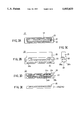
- FIG. 1A shows the construction of a conventional connector cable 11A including a connector 12 and cooperating a cable assembly 15 designed according to the SCSI-II protocol, wherein the connector includes pins or contact elements disposed in two rows.
- the connector 12 includes a contact part 13 and a cable interface part 14, wherein the contact part 13 includes contact elements for electric connection to a corresponding connector, while the cable interface part 14 is provided with two rows of terminals in electrical connection to the corresponding contact elements of the contact part 13, for connection of the cable assembly 15.
- the cable assembly 15 is formed of two flat cables 15a and 15b, and each cable forming the flat cables 15a and 15b is connected to a corresponding terminal by way of press contact achieved by connector housings 16a and 16b. It should be noted that each of the cables 15a and 15b extend in the direction of insertion of the connector cable 11A to a corresponding socket or connector.
- FIG. 1B shows another conventional connector cable 11B formed of a connector 17 and a cable assembly 15.
- the connector 17 includes a contact part 18 and a cable interface part 19, wherein the contact part 18 includes contact elements for interconnection to a corresponding socket or connector.
- the cable interface part 19 has terminals in electrical connection to the contact elements in the contact part 18, for connection of the flat cables 15a and 15b.
- the individual cables forming the flat cables 15a and 15b are connected to corresponding cable terminals by way of press contact at a connector housing 20, and the flat cables 15a and 15b extend from both sides of the housing 20.
- Another and more specific object of the present invention is to provide a flat cable and a connector using such a flat cable wherein occurrence of crosstalk in the flat cable is minimized, even in the case that the connector is designed according to a pin assignment in which one of the two rows of pins of the connector is used exclusively for carrying signals.
- Another object of the present invention is to provide a flat cable, comprising:
- a plurality of cables each including a conductive core and an insulating cover for insulating the conductive core, said plurality of cables being disposed substantially parallel with each other and aligned in a single row when viewed from an elongating direction of said cables, with a mutual separation;
- fixture means for holding said plurality of cables such that said plurality of cables are held each other with said mutual separation.
- Another object of the present invention is to provide a flat connector cable assembly, comprising:
- a connector including: a contact part for contact engagement with another connector; and a cable interface part;
- said contact part including: conductive contact elements provided in two rows for contact engagement with said another connector; and terminals aligned in two rows in correspondence to and in electrical connection to said contact elements;
- said flat cable assembly comprising first and second flat cables each including:
- a plurality of cables each including a conductive core and an insulating cover for insulating said conductive core, said plurality of cables being disposed substantially parallel with each other and aligned in a single row when viewed from an elongating direction of the said cables, with a mutual separation such that gaps are formed between said plurality of cables;
- fixture means for holding said plurality of cables forming said first and second flat cables substantially in a row when viewed from an elongating direction of said cables to form a single flat cable, such that said plurality of cables forming said second flat cable are held in respective gaps formed between said cables of said first flat cable and such that said plurality of cables forming said first flat cable are held in respective gaps of said cables forming said second flat cable.
- said first and second flat cables are fixed with each other by said fixture means, such that the cables of said first flat cable and the cables of said second flat cable are repeated alternately in said single flat cable formed by the fixture means.
- one of the first and second flat cables such as the first flat cable is used for carrying signals while the second flat cable is used for supplying electric power in compliance with the SCSI-II protocol.
- the cable for carrying a signal and the cable for carrying electric power are repeated alternately in the single flat cable formed by the fixture means.
- FIG. 2 is a diagram showing the overall construction of the flat cable connector according to a first embodiment of the present invention
- FIGS. 3A-3E are diagrams showing the construction of a connector forming a part of the flat cable connector of FIG. 2;
- FIGS. 4A and 4B are diagrams showing the construction of flat cables used in the flat cable connector of FIG. 2;
- FIGS. 5A-5C are diagrams showing the process of forming a single integral flat cable used in the flat cable connector of FIG. 2 from two separate flat cables;
- FIG. 6 is a diagram showing the overall construction of the flat cable connector according to a second embodiment of the present invention.
- FIGS. 7A-7E are diagrams showing the construction of a connector forming a part of the flat cable connector of FIG. 6.
- FIG. 2 shows a flat cable connector 21 according to a first embodiment of the present invention in a perspective view.
- the flat cable 23 includes a plurality of cables 41 extending parallel with each other and aligned in a single row when viewed from an extending direction of said cables 41, except for the foregoing first end. Further, the flat cable 23 includes a through-type intermediate connector 28 at an intermediate position of the cable 23 for branching the cables, and further carries an end connector 29 at an opposite, second end. The connector 22 and the end connector 29 are used for connecting various information processing apparatuses by way of the flat cable 23.
- FIGS. 3A-3E show the connector 22 in detail, wherein FIG. 3A shows the contact part 25 of the connector 22 in a front view, FIG. 3B shows the contact part 25 in a plan view, and FIG. 3C shows the contact part 25 in a side view. Further, FIG. 3D shows the cable connection interface part 26 in a rear view of the connector 22, while FIG. 3E shows housing members 27b and 27b cooperating with the cable connection interface part 26 of FIG. 3D.
- the contact part 25 carries a guide member 31 for mechanical-engagement with a corresponding guide member of another connector, as well as two rows of contact elements 32 of a conductive material for contact engagement with corresponding contact elements of the corresponding connector. It should be noted that the contact part including the guide 31 and the contact elements 32 are designed in compliance with the SCSI-II protocol.
- Each of the housing members 27b and 27b of FIG. 3E is formed of a rigid insulating member provided with predetermined depressions corresponding to the pins 34a and 34b. Each of the depressions forms a groove having a width corresponding to the diameter of the cables 41 forming the flat cables 24a and 24b.
- the individual cables 41 forming the flat cable 24a are held in corresponding grooves of the housing member 27b, and the housing member 27b is placed over the region 33a such that the grooves engage with the corresponding pins 34a on the region 33a.
- the individual cables 41 of the flat cable 24b are held in corresponding grooves of the housing member 27b, and the housing member 26b is placed below the region 33b such that the grooves engage with the corresponding pins 34b on the region 33b. Further, by urging the housing members 27b and 27b to approach with each other by applying a force, the sharp-pointed pins 34a on the region 33a penetrate through the insulating coating of the cables 41 held in the grooves, and the pins 34a establish a desired electrical contact with the conductive cores of the cables 41 forming the flat cable 24a.
- the sharp-pointed pins 34b on the region 33b penetrate through the insulating coating of the cables 41 held in the grooves and the pins 34b establish a desired electrical contact with the conductive cores of the cables 41 forming the flat cable 24b.
- FIGS. 4A and 4B show the construction of the flat cables 24a and 24b of FIG. 2 in detail with reference to FIGS. 4A and 4B, wherein FIG. 4A shows the cable 41 in a plan view while FIG. 4B shows the cable 41 in the cross sectional view.
- FIGS. 4A and 4B the construction of the flat cable 24a is identical with the construction of the flat cable 24b. Thus, the description will be given only to the construction of the flat cable 24a.
- a plurality of the cables 41 forming the flat cable 24a and extending generally parallel with each other are fixed upon a fusible tape 43 with a predetermined mutual separation or gap 42.
- six of such cables 41 each having a diameter ⁇ are disposed, and the flat cable 24a has a total width ⁇ .
- each of the cables 41 has a triangular cross section and disposed with a mutual separation of less than 2 ⁇ , wherein it will be noted that the fusible tape 43 is fused or welded upon the triangular cables 41 such that the apex of the triangular cable is bonded firmly upon the fusible tape 43.
- the separation between the cables 41 at the base part of the triangles becomes smaller than the diameter ⁇ of the individual cable 41.
- the fusible tape 43 is formed of a material such as polyester or polyethylene that causes a fusion bonding with the insulating coating of the cable 41 upon heating.
- the fusible tape 43 has a width of 4 cm in the extending direction of the cables 41, and two such tapes 43 are provided along the cables 41 with a separation of 4 mm+ ⁇ , wherein e represents the width of the flat cable 24a formed form the cables 41.
- the flat cable 24b is formed similarly.
- the two flat cables, 24a and 24b extend adjacent to each other from the connector 24 as indicated in FIG. 2, wherein the flat cables 24a and 24b form two separate cable portions facing each other at the foregoing first end of the flat cable 23.
- FIGS. 5A-5C show the flat cable 24a in the state that the cables 41 are bonded to the fusible tape 43 at the top apex.
- FIG. 5A shows the flat cable 24a in the state that the cables 41 are bonded to the fusible tape 43 at the top apex.
- the cables 41 of FIG. 5A are used for carrying the signals and designated in FIG. 5A as "S.”
- FIG. 5B shows the flat cable 24b in the state that the cables 41 are bonded to the fusible tape 43 at the bottom apex.
- the cables 41 of FIG. 5B are used for supplying electric power including the ground level and designated as "G.”
- the flat cable 24a of FIG. 5A and the flat cable 24b of FIG. 5B are then pressed with each other as indicated in FIGS. 5A and 5B by arrows.
- the triangular cables 41 of FIG. 5A and the triangular cables 41 of FIG. 5B experience an elastic engagement with each other as indicated in FIG. 5C.
- the cables 41 designated as "S” for the signals such as clocks and data and the cables 41 designated as "G” for the power supply are repeated alternately to form a single flat cable corresponding to the flat cable 23 of FIG. 2.
- the flat cables 24a and 24b are configured to form a single flat cable as described above, it becomes possible to eliminate the crosstalk between the signal lines in the flat cable 24a substantially while still complying with the SCSI-II protocol at the connector 22. Further, it is possible to connect similar flat cables by way of the through type connector 28 as indicated in FIG. 1.
- the cross section of the cables is not limited to the triangular cross section but may be a mushroom-like cross section or any other cross section that is effective for elastic engagement between the cables in the state of FIG. 5C. Further, one may form a flat cable from the flat cables 24a and 24b without specific cross sectional shape for the cables 41 as long as the cables 41 are held With each other by suitable holding means.
- FIG. 6 those parts corresponding to the parts described previously are designated by the corresponding reference numerals and the description thereof will be omitted.
- the flat cable connector 21 has a connector 22a in which the flat cables 24a and 24b are connected to the connector 22a at both lateral sides thereof such that the cables in the flat cable 24a and the cables in the flat cable 24b oppose with each other.
- the connector 22a includes a contact part 51 for engagement with another connector and a cable connection interface part 52, wherein the contact part 51 corresponds to the contact part 25 and the cable connection interface part 52 corresponds to the cable connection interface 26 of FIG. 2.
- the interface part 52 includes a housing element 53 for achieving the press contact of the cables 24a and 24b upon the interface part 52.
- FIGS. 7A-7C show the construction of the contact part 51 of the connector 22a, wherein FIG. 7A shows the contact part 51 in a front view, FIG. 7B shows the contact part 51 in a plan view, and FIG. 7C shows the contact part 51 in a side view. Further, FIGS. 7D and 7E show the housing element 53 respectively in the front view and in the plan view.
- the contact part 51 has a guide 54 for mechanical engagement with another connector, and contact elements 55 of a conductive material are provided in the guide 54 in two rows in compliance with the SCSI-II protocol.
- the cable connection interface part 52 is formed of an upper first region 55a and a lower second region 55b separated from each other by an intervening insulator member 55, wherein the first region 55a carries a plurality of sharply-pointed pins 56a in electrical connection to the contact elements 54 forming the upper row in FIG. 7A. Similarly, the second region 55b carries a plurality of sharply-pointed pins 56b in electrical connection to the contact elements 54 forming the lower row in FIG. 7A. It should be noted that the first and second regions 55a and 55b commonly face in the rear direction of the connector 22a, and the sharply-pointed pins 56a and 56b extend also in the rear direction of the connector 22a.
- the housing element 53 carries thereon a number of grooves 57 in correspondence to the sharply-pointed pins 56a or 56b on the cable connection interface part 52.
- the sharp-pointed pins 56a and 56b penetrate into the cables 41 through the insulating coating and the desired electric connection is achieved between the conductive core 41b of the cables 41 and the pins 56a and 56b.
- the cables 24a and 24b are assembled to form the single flat cable 23 similarly to the embodiment of FIGS. 5A-5C.
Abstract
A flat connector cable assembly includes a connector having two rows of contact elements, a flat cable assembly formed of first and second flat cables respectively connected to first rows and second rows of the contact elements, and a fixture element for holding the first and second flat cables to form a single flat cable, wherein the fixture element holds the plurality of cables of the second flat cable with gaps formed therebetween such that the plurality of cables of the first flat cable are held in respective gaps formed between the cables of the second flat cable, and such that the fixture element holds the plurality of cables of the first flat cable with gaps formed therebetween such that the plurality of cables of the second flat cable are held in respective gaps formed between the cables of the first flat cable.
Description
This is a division of application Ser. No. 08/278,226, filed Jul. 21, 1994.
The present invention relates to a flat cable and a connector cooperating therewith for transmitting information signals in information processing apparatuses.
With increase in the number of signals to be processed in recent information processing apparatuses, use of so-called flat cables is increasing for transmitting the signals between various information processing apparatuses. Most of such flat cables and corresponding connectors are designed according to the SCSI (small computer system interface)-II protocol known also as FAST-SCSI prescribed by ANSI (American National Standard Institute), particularly with regard to the pin assignment. Thus, there is a need to design the flat cables and connectors in compliance with the SCSI-II protocol while minimizing crosstalk between the signal cables.
Conventionally, the flat cables have been designed such that signal cables for carrying signals and power cables for supplying the electric power have been disposed alternately for avoiding crosstalk between the signals. By disposing the signal cables and the power cables alternately in the flat cable, it is possible to minimize the adversary effect on the waveform of the signals transmitted along the signal cables. Thus, the connector provided at an end of such a flat cable also has a pin assignment such that the pins for the signal cables and the pins for the power cables are disposed alternately.
In the foregoing SCSI-II interface, on the other hand, it is prescribed such that two rows of pins are provided in the connector and such that the pins for signals are only in one of the foregoing two rows of the pins.
FIG. 1A shows the construction of a conventional connector cable 11A including a connector 12 and cooperating a cable assembly 15 designed according to the SCSI-II protocol, wherein the connector includes pins or contact elements disposed in two rows.
Referring to FIG. 1A, it will be noted that the connector 12 includes a contact part 13 and a cable interface part 14, wherein the contact part 13 includes contact elements for electric connection to a corresponding connector, while the cable interface part 14 is provided with two rows of terminals in electrical connection to the corresponding contact elements of the contact part 13, for connection of the cable assembly 15. The cable assembly 15, in turn, is formed of two flat cables 15a and 15b, and each cable forming the flat cables 15a and 15b is connected to a corresponding terminal by way of press contact achieved by connector housings 16a and 16b. It should be noted that each of the cables 15a and 15b extend in the direction of insertion of the connector cable 11A to a corresponding socket or connector.
FIG. 1B shows another conventional connector cable 11B formed of a connector 17 and a cable assembly 15. The connector 17 includes a contact part 18 and a cable interface part 19, wherein the contact part 18 includes contact elements for interconnection to a corresponding socket or connector. On the other hand, the cable interface part 19 has terminals in electrical connection to the contact elements in the contact part 18, for connection of the flat cables 15a and 15b. The individual cables forming the flat cables 15a and 15b are connected to corresponding cable terminals by way of press contact at a connector housing 20, and the flat cables 15a and 15b extend from both sides of the housing 20.
Thus, the foregoing conventional connector cables 11A and 11B have the feature that two flat cables 15a and 15b extend from the cable interface part 14 or 19. In any of the connector cables 11A and 11B, it is necessary to use one of the flat cables such as the flat cable 15a explicitly for carrying signals and the other flat cable 15b explicitly for carrying the electric power, in order to design the connector 12 or 17 in compliance with the pin assignment of the SCSI-II protocol.
In the foregoing connector 11A or 11B designed as such, it should be noted that the signal cables and the power cables are no longer disposed alternately in the flat cables 15a and 15b. Thus, there occurs a problem in that such conventional SCSI-II cable connectors are vulnerable to crosstalk of the signals in the flat cables.
Accordingly, it is a general object of the present invention to provide a novel and useful flat cable and a connector using such a flat cable wherein the foregoing problems are eliminated.
Another and more specific object of the present invention is to provide a flat cable and a connector using such a flat cable wherein occurrence of crosstalk in the flat cable is minimized, even in the case that the connector is designed according to a pin assignment in which one of the two rows of pins of the connector is used exclusively for carrying signals.
Another object of the present invention is to provide a flat cable, comprising:
a plurality of cables each including a conductive core and an insulating cover for insulating the conductive core, said plurality of cables being disposed substantially parallel with each other and aligned in a single row when viewed from an elongating direction of said cables, with a mutual separation; and
fixture means for holding said plurality of cables such that said plurality of cables are held each other with said mutual separation.
Another object of the present invention is to provide a flat connector cable assembly, comprising:
a connector including: a contact part for contact engagement with another connector; and a cable interface part; and
a flat cable assembly in connection to said cable interface part of said connector;
said contact part including: conductive contact elements provided in two rows for contact engagement with said another connector; and terminals aligned in two rows in correspondence to and in electrical connection to said contact elements;
said flat cable assembly comprising first and second flat cables each including:
a plurality of cables each including a conductive core and an insulating cover for insulating said conductive core, said plurality of cables being disposed substantially parallel with each other and aligned in a single row when viewed from an elongating direction of the said cables, with a mutual separation such that gaps are formed between said plurality of cables; and
fixture means for holding said plurality of cables forming said first and second flat cables substantially in a row when viewed from an elongating direction of said cables to form a single flat cable, such that said plurality of cables forming said second flat cable are held in respective gaps formed between said cables of said first flat cable and such that said plurality of cables forming said first flat cable are held in respective gaps of said cables forming said second flat cable.
According to the present invention, said first and second flat cables are fixed with each other by said fixture means, such that the cables of said first flat cable and the cables of said second flat cable are repeated alternately in said single flat cable formed by the fixture means. Further, one of the first and second flat cables such as the first flat cable is used for carrying signals while the second flat cable is used for supplying electric power in compliance with the SCSI-II protocol. Thus, it is possible to clear the requirement of the SCSI-II protocol with regard to the arrangement of the conductive contact elements at the connector while simultaneously minimizing crosstalk between the signals carried by the first flat cable. It should be noted that the cable for carrying a signal and the cable for carrying electric power are repeated alternately in the single flat cable formed by the fixture means.
Other objects and further features of the present invention will become apparent from the following detailed description when read in conjunction with the attached drawings.
FIGS. 1A and 1B show the construction of conventional flat cable connectors;
FIG. 2 is a diagram showing the overall construction of the flat cable connector according to a first embodiment of the present invention;
FIGS. 3A-3E are diagrams showing the construction of a connector forming a part of the flat cable connector of FIG. 2;
FIGS. 4A and 4B are diagrams showing the construction of flat cables used in the flat cable connector of FIG. 2;
FIGS. 5A-5C are diagrams showing the process of forming a single integral flat cable used in the flat cable connector of FIG. 2 from two separate flat cables;
FIG. 6 is a diagram showing the overall construction of the flat cable connector according to a second embodiment of the present invention; and
FIGS. 7A-7E are diagrams showing the construction of a connector forming a part of the flat cable connector of FIG. 6.
FIG. 2 shows a flat cable connector 21 according to a first embodiment of the present invention in a perspective view.
Referring to FIG. 2, the flat cable connector 21 includes a connector 22 and a flat cable 23 having a first end connected to the connector 22. The flat cable 23 is actually formed of two flat cables 24a and 24b as will be described later in detail. On the other hand, the connector 22 is formed of a contact part 25 for engagement with a corresponding connector and a cable connection interface part 26 for connecting the flat cable 23 upon the connector 22. As will be described with reference to FIGS. 3A-3E, the cable connection interface part 26 includes first and second housing members 27b and 27b that achieve a press engagement of the flat cables 24a and 24b upon the interface part 26.
It should be noted that the flat cable 23 includes a plurality of cables 41 extending parallel with each other and aligned in a single row when viewed from an extending direction of said cables 41, except for the foregoing first end. Further, the flat cable 23 includes a through-type intermediate connector 28 at an intermediate position of the cable 23 for branching the cables, and further carries an end connector 29 at an opposite, second end. The connector 22 and the end connector 29 are used for connecting various information processing apparatuses by way of the flat cable 23.
FIGS. 3A-3E show the connector 22 in detail, wherein FIG. 3A shows the contact part 25 of the connector 22 in a front view, FIG. 3B shows the contact part 25 in a plan view, and FIG. 3C shows the contact part 25 in a side view. Further, FIG. 3D shows the cable connection interface part 26 in a rear view of the connector 22, while FIG. 3E shows housing members 27b and 27b cooperating with the cable connection interface part 26 of FIG. 3D.
As shown in FIG. 3A, the contact part 25 carries a guide member 31 for mechanical-engagement with a corresponding guide member of another connector, as well as two rows of contact elements 32 of a conductive material for contact engagement with corresponding contact elements of the corresponding connector. It should be noted that the contact part including the guide 31 and the contact elements 32 are designed in compliance with the SCSI-II protocol.
As indicated in FIG. 3B, the cable connection interface part 26 is formed behind the contact part 25 in continuation therewith, wherein the interface part 26 includes an upper region 33a and a lower region 33b separated from each other by an insulating member 33 as indicated in the side view of FIG. 3C. Further, as will be noted from FIG. 3D, terminals 34a and 34b, respectively in electrical connection to the contact elements 32, are provided on the upper region 33a and the lower region 33b as indicated in FIG. 3D, wherein the contact elements 32 forming the upper row in FIG. 3A are connected to the terminals 34a and the contact elements 32 forming the lower row are connected to the terminals 34b. Each of the terminals 34a forms a sharp-pointed pin extending upward from the region 33a. Similarly, each of the terminals 34b forms a sharp pointed pin extending downward from the region 33b.
Each of the housing members 27b and 27b of FIG. 3E, on the other hand, is formed of a rigid insulating member provided with predetermined depressions corresponding to the pins 34a and 34b. Each of the depressions forms a groove having a width corresponding to the diameter of the cables 41 forming the flat cables 24a and 24b. Thus, the individual cables 41 forming the flat cable 24a are held in corresponding grooves of the housing member 27b, and the housing member 27b is placed over the region 33a such that the grooves engage with the corresponding pins 34a on the region 33a. Similarly, the individual cables 41 of the flat cable 24b are held in corresponding grooves of the housing member 27b, and the housing member 26b is placed below the region 33b such that the grooves engage with the corresponding pins 34b on the region 33b. Further, by urging the housing members 27b and 27b to approach with each other by applying a force, the sharp-pointed pins 34a on the region 33a penetrate through the insulating coating of the cables 41 held in the grooves, and the pins 34a establish a desired electrical contact with the conductive cores of the cables 41 forming the flat cable 24a. Similarly, the sharp-pointed pins 34b on the region 33b penetrate through the insulating coating of the cables 41 held in the grooves and the pins 34b establish a desired electrical contact with the conductive cores of the cables 41 forming the flat cable 24b.
Next, the construction of the flat cables 24a and 24b of FIG. 2 will be described in detail with reference to FIGS. 4A and 4B, wherein FIG. 4A shows the cable 41 in a plan view while FIG. 4B shows the cable 41 in the cross sectional view. In FIGS. 4A and 4B, the construction of the flat cable 24a is identical with the construction of the flat cable 24b. Thus, the description will be given only to the construction of the flat cable 24a.
Referring to FIG. 4A, a plurality of the cables 41 forming the flat cable 24a and extending generally parallel with each other are fixed upon a fusible tape 43 with a predetermined mutual separation or gap 42. In the illustrated example, six of such cables 41 each having a diameter β are disposed, and the flat cable 24a has a total width α.
Referring to the cross sectional view of FIG. 4B, it will be noted that each of the cables 41 has a triangular cross section and disposed with a mutual separation of less than 2β, wherein it will be noted that the fusible tape 43 is fused or welded upon the triangular cables 41 such that the apex of the triangular cable is bonded firmly upon the fusible tape 43. By bonding the cables 41 upon the tape 43 in the form of inverted triangles with the mutual separation set smaller than 2β as indicated in FIG. 4B, the separation between the cables 41 at the base part of the triangles becomes smaller than the diameter β of the individual cable 41.
It should be noted that the fusible tape 43 is formed of a material such as polyester or polyethylene that causes a fusion bonding with the insulating coating of the cable 41 upon heating. Typically, the fusible tape 43 has a width of 4 cm in the extending direction of the cables 41, and two such tapes 43 are provided along the cables 41 with a separation of 4 mm+α, wherein e represents the width of the flat cable 24a formed form the cables 41.
The flat cable 24b is formed similarly. Thus, the two flat cables, 24a and 24b, extend adjacent to each other from the connector 24 as indicated in FIG. 2, wherein the flat cables 24a and 24b form two separate cable portions facing each other at the foregoing first end of the flat cable 23.
The flat cables 24a and 24b are assembled with each other at the foregoing fusible tape 43 as indicated in FIGS. 5A-5C, wherein FIG. 5A shows the flat cable 24a in the state that the cables 41 are bonded to the fusible tape 43 at the top apex. It should be noted that the cables 41 of FIG. 5A are used for carrying the signals and designated in FIG. 5A as "S." FIG. 5B, on the other hand, shows the flat cable 24b in the state that the cables 41 are bonded to the fusible tape 43 at the bottom apex. The cables 41 of FIG. 5B are used for supplying electric power including the ground level and designated as "G."
The flat cable 24a of FIG. 5A and the flat cable 24b of FIG. 5B are then pressed with each other as indicated in FIGS. 5A and 5B by arrows. Thereby, the triangular cables 41 of FIG. 5A and the triangular cables 41 of FIG. 5B experience an elastic engagement with each other as indicated in FIG. 5C. In the state of FIG. 5C, it should be noted that the cables 41 designated as "S" for the signals such as clocks and data and the cables 41 designated as "G" for the power supply are repeated alternately to form a single flat cable corresponding to the flat cable 23 of FIG. 2.
Thus, by configuring the flat cables 24a and 24b to form a single flat cable as described above, it becomes possible to eliminate the crosstalk between the signal lines in the flat cable 24a substantially while still complying with the SCSI-II protocol at the connector 22. Further, it is possible to connect similar flat cables by way of the through type connector 28 as indicated in FIG. 1. In the foregoing embodiment, it should be noted that the cross section of the cables is not limited to the triangular cross section but may be a mushroom-like cross section or any other cross section that is effective for elastic engagement between the cables in the state of FIG. 5C. Further, one may form a flat cable from the flat cables 24a and 24b without specific cross sectional shape for the cables 41 as long as the cables 41 are held With each other by suitable holding means.
Next, a flat cable connector 21a according to a second embodiment of the present invention will be described with reference to FIG. 6. In FIG. 6, those parts corresponding to the parts described previously are designated by the corresponding reference numerals and the description thereof will be omitted.
Referring to FIG. 6 showing the flat cable connector 21 in a perspective view, it will be noted that the flat cable connector 21 has a connector 22a in which the flat cables 24a and 24b are connected to the connector 22a at both lateral sides thereof such that the cables in the flat cable 24a and the cables in the flat cable 24b oppose with each other.
More specifically, the connector 22a includes a contact part 51 for engagement with another connector and a cable connection interface part 52, wherein the contact part 51 corresponds to the contact part 25 and the cable connection interface part 52 corresponds to the cable connection interface 26 of FIG. 2. The interface part 52 includes a housing element 53 for achieving the press contact of the cables 24a and 24b upon the interface part 52.
FIGS. 7A-7C show the construction of the contact part 51 of the connector 22a, wherein FIG. 7A shows the contact part 51 in a front view, FIG. 7B shows the contact part 51 in a plan view, and FIG. 7C shows the contact part 51 in a side view. Further, FIGS. 7D and 7E show the housing element 53 respectively in the front view and in the plan view.
Referring to FIG. 7A, the contact part 51 has a guide 54 for mechanical engagement with another connector, and contact elements 55 of a conductive material are provided in the guide 54 in two rows in compliance with the SCSI-II protocol.
As indicated in FIGS. 7B and 7C, the cable connection interface part 52 is formed of an upper first region 55a and a lower second region 55b separated from each other by an intervening insulator member 55, wherein the first region 55a carries a plurality of sharply-pointed pins 56a in electrical connection to the contact elements 54 forming the upper row in FIG. 7A. Similarly, the second region 55b carries a plurality of sharply-pointed pins 56b in electrical connection to the contact elements 54 forming the lower row in FIG. 7A. It should be noted that the first and second regions 55a and 55b commonly face in the rear direction of the connector 22a, and the sharply-pointed pins 56a and 56b extend also in the rear direction of the connector 22a.
Further, the housing element 53 carries thereon a number of grooves 57 in correspondence to the sharply-pointed pins 56a or 56b on the cable connection interface part 52. Thus, by holding the cables 41 forming the flat cables 24a and 24b in the corresponding grooves 57 of the respective housing members 53 and urging the respective housing members 53 firmly against the regions 55a and 55b of the interface part 52, the sharp-pointed pins 56a and 56b penetrate into the cables 41 through the insulating coating and the desired electric connection is achieved between the conductive core 41b of the cables 41 and the pins 56a and 56b.
In the present embodiment, the cables 24a and 24b are assembled to form the single flat cable 23 similarly to the embodiment of FIGS. 5A-5C.
Further, the present invention is not limited to the embodiments described heretofore, but various variations and modifications may be made without departing from the scope of the invention.
Claims (2)
1. A flat cable connector assembly, comprising:
a connector including: a contact part for contact engagement with another connector; and a cable interface part; and
a flat cable assembly in connection to said cable interface part of said connector;
said contact part including: conductive contact elements provided in two rows for contact engagement with said other connector; and terminals aligned in two rows in correspondence to and in electrical connection to said contact elements;
said flat cable assembly comprising first and second flat cables each including:
a plurality of cables each including a conductive core and an insulating cover for insulating said conductive core, said plurality of cables being disposed substantially parallel with each other and aligned in a single row when viewed from an elongating direction of said cables, with a mutual separation such that gaps are formed between said plurality of cables; and
fixture means for holding said plurality of cables forming said first and second flat cables substantially in a row when viewed from an elongating direction of said cables to form a single flat cable, such that said plurality of cables forming said second flat cable are held in respective gaps formed between said cables of said first flat cable and such that said plurality of cables forming said first flat cable are held in respective gaps of said cables forming said second flat cable;
wherein each of said cables forming said first and second flat cables have a triangular cross section, said fixture means comprises a first fixture member carrying thereon said cables of said first flat cable by bonding to an apex of said triangular cross section, and a second fixture member carrying thereon said cables of said second flat cable by bonding to an apex of said triangular cross section, wherein said cables of said first flat cable and said cables of said second flat cable establish a mechanical engagement.
2. A flat cable connector as claimed in claim 1, wherein said first and second fixture members are formed of a fusible tape that causes a fusion to said insulating cover, and wherein said first fixture member is disposed, in said fixture means, to be coincident to a first side of said single flat cable, said second fixture member is disposed, in said fixture means, to be coincident to a second, opposite side of said single flat cable.
Priority Applications (1)
| Application Number | Priority Date | Filing Date | Title |
|---|---|---|---|
| US08/385,921 US5603633A (en) | 1993-09-22 | 1995-02-09 | Flat cable and a connector cooperating therewith |
Applications Claiming Priority (4)
| Application Number | Priority Date | Filing Date | Title |
|---|---|---|---|
| JP5236797A JPH0794034A (en) | 1993-09-22 | 1993-09-22 | Flat cable and flat cable with connector |
| JP5-236797 | 1993-09-22 | ||
| US08/278,226 US5499928A (en) | 1993-09-22 | 1994-07-21 | Flat cable and a connector cooperating therewith |
| US08/385,921 US5603633A (en) | 1993-09-22 | 1995-02-09 | Flat cable and a connector cooperating therewith |
Related Parent Applications (1)
| Application Number | Title | Priority Date | Filing Date |
|---|---|---|---|
| US08/278,226 Division US5499928A (en) | 1993-09-22 | 1994-07-21 | Flat cable and a connector cooperating therewith |
Publications (1)
| Publication Number | Publication Date |
|---|---|
| US5603633A true US5603633A (en) | 1997-02-18 |
Family
ID=17005938
Family Applications (2)
| Application Number | Title | Priority Date | Filing Date |
|---|---|---|---|
| US08/278,226 Expired - Fee Related US5499928A (en) | 1993-09-22 | 1994-07-21 | Flat cable and a connector cooperating therewith |
| US08/385,921 Expired - Fee Related US5603633A (en) | 1993-09-22 | 1995-02-09 | Flat cable and a connector cooperating therewith |
Family Applications Before (1)
| Application Number | Title | Priority Date | Filing Date |
|---|---|---|---|
| US08/278,226 Expired - Fee Related US5499928A (en) | 1993-09-22 | 1994-07-21 | Flat cable and a connector cooperating therewith |
Country Status (2)
| Country | Link |
|---|---|
| US (2) | US5499928A (en) |
| JP (1) | JPH0794034A (en) |
Cited By (7)
| Publication number | Priority date | Publication date | Assignee | Title |
|---|---|---|---|---|
| EP0852410A2 (en) * | 1997-01-03 | 1998-07-08 | Molex Incorporated | Electrical circuit arrangement |
| US6068504A (en) * | 1998-09-08 | 2000-05-30 | Molex Incorporated | Selective termination connector assembly |
| US6179644B1 (en) * | 1997-11-07 | 2001-01-30 | Rockwell Technologies, Llc | Power and data network system media architecture |
| US20040218395A1 (en) * | 2003-05-02 | 2004-11-04 | Jurgen Westerheide | Bendable low voltage contact rail for track lighting systems |
| US20060141848A1 (en) * | 2004-12-29 | 2006-06-29 | Topower Computer Industrial Co., Ltd. | Power cord electric connection structure |
| US20070093123A1 (en) * | 2005-10-21 | 2007-04-26 | Ezminer, Inc. | Journal printer data interrupt cable for real time data capture at the keystroke and scan level |
| US20160197460A1 (en) * | 2013-08-09 | 2016-07-07 | Autonetworks Technologies, Ltd. | Wire harness and connector |
Families Citing this family (9)
| Publication number | Priority date | Publication date | Assignee | Title |
|---|---|---|---|---|
| JP3011041B2 (en) * | 1995-01-20 | 2000-02-21 | 住友電装株式会社 | Flat multi-core wire |
| US6207392B1 (en) * | 1997-11-25 | 2001-03-27 | The Regents Of The University Of California | Semiconductor nanocrystal probes for biological applications and process for making and using such probes |
| US6253893B1 (en) * | 1999-01-29 | 2001-07-03 | Hu Chi-Min | Flat cable type extension wire |
| US6428347B1 (en) * | 2000-10-12 | 2002-08-06 | 3Com Corporation | Electrical compression connection for retractable connectors |
| US6805946B2 (en) * | 2000-12-04 | 2004-10-19 | Advanced Ceramics Research, Inc. | Multi-functional composite structures |
| TW493308B (en) * | 2000-12-30 | 2002-07-01 | Hon Hai Prec Ind Co Ltd | Cable sorting method |
| DE102007047679B4 (en) * | 2007-10-05 | 2011-03-10 | Multitest Elektronische Systeme Gmbh | Plunger for moving electronic components, in particular ICs, with Wärmeleitkörper |
| JP2013154506A (en) * | 2012-01-27 | 2013-08-15 | Fuji Xerox Co Ltd | Signal transmission path, exposure device and image forming apparatus |
| CN107767995B (en) * | 2017-09-23 | 2023-10-03 | 立讯精密工业股份有限公司 | round cable |
Citations (13)
| Publication number | Priority date | Publication date | Assignee | Title |
|---|---|---|---|---|
| US3097036A (en) * | 1957-01-08 | 1963-07-09 | Burndy Corp | Flexible multiple connector |
| US4171860A (en) * | 1977-03-17 | 1979-10-23 | Teradyne, Inc. | Testing circuit boards |
| US4230898A (en) * | 1977-10-19 | 1980-10-28 | Emmel Leroy L | Elongated filament lattice structure |
| JPS5998409A (en) * | 1982-11-26 | 1984-06-06 | 富士通株式会社 | Flat cable |
| US4484791A (en) * | 1980-07-03 | 1984-11-27 | E. I. Du Pont De Nemours And Company | Connector for multiconductor flat insulated cable |
| US4486619A (en) * | 1983-05-12 | 1984-12-04 | Minnesota Mining And Manufacturing Company | Uniform twisted wire pair electrical ribbon cable |
| US4925401A (en) * | 1989-05-23 | 1990-05-15 | Amp Incorporated | Electrical connector assembly with strain relief |
| US5041009A (en) * | 1987-08-31 | 1991-08-20 | Amp Incorporated | Daisy chain connector and method |
| US5104336A (en) * | 1989-10-27 | 1992-04-14 | Kel Corporation | Flat cable connector |
| US5326286A (en) * | 1992-12-17 | 1994-07-05 | Molex Incorporated | Electrical connector assembly with terminal alignment system |
| US5327513A (en) * | 1992-05-28 | 1994-07-05 | Raychem Corporation | Flat cable |
| US5332395A (en) * | 1993-02-16 | 1994-07-26 | Wen Yu Tang | Computer cable connectors |
| US5338221A (en) * | 1993-06-09 | 1994-08-16 | Molex Incorporated | Electrical connector for high density ribbon cable |
Family Cites Families (1)
| Publication number | Priority date | Publication date | Assignee | Title |
|---|---|---|---|---|
| US3087036A (en) * | 1960-09-30 | 1963-04-23 | Phillips Petroleum Co | Mercury rotary switch |
-
1993
- 1993-09-22 JP JP5236797A patent/JPH0794034A/en active Pending
-
1994
- 1994-07-21 US US08/278,226 patent/US5499928A/en not_active Expired - Fee Related
-
1995
- 1995-02-09 US US08/385,921 patent/US5603633A/en not_active Expired - Fee Related
Patent Citations (13)
| Publication number | Priority date | Publication date | Assignee | Title |
|---|---|---|---|---|
| US3097036A (en) * | 1957-01-08 | 1963-07-09 | Burndy Corp | Flexible multiple connector |
| US4171860A (en) * | 1977-03-17 | 1979-10-23 | Teradyne, Inc. | Testing circuit boards |
| US4230898A (en) * | 1977-10-19 | 1980-10-28 | Emmel Leroy L | Elongated filament lattice structure |
| US4484791A (en) * | 1980-07-03 | 1984-11-27 | E. I. Du Pont De Nemours And Company | Connector for multiconductor flat insulated cable |
| JPS5998409A (en) * | 1982-11-26 | 1984-06-06 | 富士通株式会社 | Flat cable |
| US4486619A (en) * | 1983-05-12 | 1984-12-04 | Minnesota Mining And Manufacturing Company | Uniform twisted wire pair electrical ribbon cable |
| US5041009A (en) * | 1987-08-31 | 1991-08-20 | Amp Incorporated | Daisy chain connector and method |
| US4925401A (en) * | 1989-05-23 | 1990-05-15 | Amp Incorporated | Electrical connector assembly with strain relief |
| US5104336A (en) * | 1989-10-27 | 1992-04-14 | Kel Corporation | Flat cable connector |
| US5327513A (en) * | 1992-05-28 | 1994-07-05 | Raychem Corporation | Flat cable |
| US5326286A (en) * | 1992-12-17 | 1994-07-05 | Molex Incorporated | Electrical connector assembly with terminal alignment system |
| US5332395A (en) * | 1993-02-16 | 1994-07-26 | Wen Yu Tang | Computer cable connectors |
| US5338221A (en) * | 1993-06-09 | 1994-08-16 | Molex Incorporated | Electrical connector for high density ribbon cable |
Cited By (10)
| Publication number | Priority date | Publication date | Assignee | Title |
|---|---|---|---|---|
| EP0852410A2 (en) * | 1997-01-03 | 1998-07-08 | Molex Incorporated | Electrical circuit arrangement |
| EP0852410A3 (en) * | 1997-01-03 | 1999-07-21 | Molex Incorporated | Electrical circuit arrangement |
| US6179644B1 (en) * | 1997-11-07 | 2001-01-30 | Rockwell Technologies, Llc | Power and data network system media architecture |
| US6068504A (en) * | 1998-09-08 | 2000-05-30 | Molex Incorporated | Selective termination connector assembly |
| US20040218395A1 (en) * | 2003-05-02 | 2004-11-04 | Jurgen Westerheide | Bendable low voltage contact rail for track lighting systems |
| US20060141848A1 (en) * | 2004-12-29 | 2006-06-29 | Topower Computer Industrial Co., Ltd. | Power cord electric connection structure |
| US7121869B2 (en) * | 2004-12-29 | 2006-10-17 | Topower Computer Industrial Co., Ltd. | Power cord electric connection structure |
| US20070093123A1 (en) * | 2005-10-21 | 2007-04-26 | Ezminer, Inc. | Journal printer data interrupt cable for real time data capture at the keystroke and scan level |
| US20160197460A1 (en) * | 2013-08-09 | 2016-07-07 | Autonetworks Technologies, Ltd. | Wire harness and connector |
| US9653894B2 (en) * | 2013-08-09 | 2017-05-16 | Autonetworks Technologies, Ltd. | Wire harness and connector |
Also Published As
| Publication number | Publication date |
|---|---|
| US5499928A (en) | 1996-03-19 |
| JPH0794034A (en) | 1995-04-07 |
Similar Documents
| Publication | Publication Date | Title |
|---|---|---|
| US5603633A (en) | Flat cable and a connector cooperating therewith | |
| US4767345A (en) | High-density, modular, electrical connector | |
| EP0214830B1 (en) | Fpc connector | |
| US4773878A (en) | Shielded flat cable connectors | |
| EP0270598B1 (en) | Shielded electrical connector | |
| US6077105A (en) | Multi-conductor cable connector with integral grounding bus | |
| CA1053765A (en) | Flat conductor flat cable adapter | |
| WO2022083683A1 (en) | Integrally shielded cable connector | |
| US6267625B1 (en) | High density electrical interconnect system having enhanced grounding and cross-talk reduction capability | |
| JPH10270133A (en) | Connector having integrated pcb assembly | |
| US5842887A (en) | Connector with improved shielding | |
| US4568136A (en) | Socket terminal strip | |
| US5658164A (en) | Flexible flat electrical cable connector with a conductive shield | |
| US6655992B1 (en) | Vertically mated micro coaxial cable connector assembly | |
| CA1128619A (en) | Circuit board interconnection system | |
| JP3267968B2 (en) | Shielded connectors for shielded cables | |
| US6634894B1 (en) | Vertically mated micro coaxial cable connector assembly with grounding shield | |
| US20040023531A1 (en) | Electrical connector with securely retained terminals | |
| US6120319A (en) | IDC connector | |
| EP0986138A2 (en) | Selective termination connector assembly | |
| US5190464A (en) | Shielded electrical connector with contact shunting arrangement | |
| US6645007B1 (en) | Vertically mated micro coaxial cable connector assembly with grounding bar | |
| JP2723250B2 (en) | Male plug connector and female socket connector | |
| US6641435B1 (en) | Vertically mated micro coaxial cable connector assembly | |
| US6811429B2 (en) | Low noise IDC terminal/pin arrangement for flat ribbon cable connectors |
Legal Events
| Date | Code | Title | Description |
|---|---|---|---|
| FEPP | Fee payment procedure |
Free format text: PAYOR NUMBER ASSIGNED (ORIGINAL EVENT CODE: ASPN); ENTITY STATUS OF PATENT OWNER: LARGE ENTITY |
|
| FPAY | Fee payment |
Year of fee payment: 4 |
|
| REMI | Maintenance fee reminder mailed | ||
| LAPS | Lapse for failure to pay maintenance fees | ||
| STCH | Information on status: patent discontinuation |
Free format text: PATENT EXPIRED DUE TO NONPAYMENT OF MAINTENANCE FEES UNDER 37 CFR 1.362 |
|
| FP | Lapsed due to failure to pay maintenance fee |
Effective date: 20050218 |