US5605154A - Two-dimensional phase correction using a deformable ultrasonic transducer array - Google Patents
Two-dimensional phase correction using a deformable ultrasonic transducer array Download PDFInfo
- Publication number
- US5605154A US5605154A US08/467,003 US46700395A US5605154A US 5605154 A US5605154 A US 5605154A US 46700395 A US46700395 A US 46700395A US 5605154 A US5605154 A US 5605154A
- Authority
- US
- United States
- Prior art keywords
- transducer
- array
- actuator
- ultrasound beam
- dimension
- Prior art date
- Legal status (The legal status is an assumption and is not a legal conclusion. Google has not performed a legal analysis and makes no representation as to the accuracy of the status listed.)
- Expired - Fee Related
Links
Images


Classifications
-
- G—PHYSICS
- G10—MUSICAL INSTRUMENTS; ACOUSTICS
- G10K—SOUND-PRODUCING DEVICES; METHODS OR DEVICES FOR PROTECTING AGAINST, OR FOR DAMPING, NOISE OR OTHER ACOUSTIC WAVES IN GENERAL; ACOUSTICS NOT OTHERWISE PROVIDED FOR
- G10K11/00—Methods or devices for transmitting, conducting or directing sound in general; Methods or devices for protecting against, or for damping, noise or other acoustic waves in general
- G10K11/18—Methods or devices for transmitting, conducting or directing sound
- G10K11/26—Sound-focusing or directing, e.g. scanning
- G10K11/34—Sound-focusing or directing, e.g. scanning using electrical steering of transducer arrays, e.g. beam steering
- G10K11/341—Circuits therefor
- G10K11/346—Circuits therefor using phase variation
-
- G—PHYSICS
- G01—MEASURING; TESTING
- G01S—RADIO DIRECTION-FINDING; RADIO NAVIGATION; DETERMINING DISTANCE OR VELOCITY BY USE OF RADIO WAVES; LOCATING OR PRESENCE-DETECTING BY USE OF THE REFLECTION OR RERADIATION OF RADIO WAVES; ANALOGOUS ARRANGEMENTS USING OTHER WAVES
- G01S15/00—Systems using the reflection or reradiation of acoustic waves, e.g. sonar systems
- G01S15/88—Sonar systems specially adapted for specific applications
- G01S15/89—Sonar systems specially adapted for specific applications for mapping or imaging
- G01S15/8906—Short-range imaging systems; Acoustic microscope systems using pulse-echo techniques
- G01S15/8934—Short-range imaging systems; Acoustic microscope systems using pulse-echo techniques using a dynamic transducer configuration
-
- G—PHYSICS
- G01—MEASURING; TESTING
- G01S—RADIO DIRECTION-FINDING; RADIO NAVIGATION; DETERMINING DISTANCE OR VELOCITY BY USE OF RADIO WAVES; LOCATING OR PRESENCE-DETECTING BY USE OF THE REFLECTION OR RERADIATION OF RADIO WAVES; ANALOGOUS ARRANGEMENTS USING OTHER WAVES
- G01S7/00—Details of systems according to groups G01S13/00, G01S15/00, G01S17/00
- G01S7/52—Details of systems according to groups G01S13/00, G01S15/00, G01S17/00 of systems according to group G01S15/00
- G01S7/52017—Details of systems according to groups G01S13/00, G01S15/00, G01S17/00 of systems according to group G01S15/00 particularly adapted to short-range imaging
- G01S7/52046—Techniques for image enhancement involving transmitter or receiver
-
- G—PHYSICS
- G01—MEASURING; TESTING
- G01S—RADIO DIRECTION-FINDING; RADIO NAVIGATION; DETERMINING DISTANCE OR VELOCITY BY USE OF RADIO WAVES; LOCATING OR PRESENCE-DETECTING BY USE OF THE REFLECTION OR RERADIATION OF RADIO WAVES; ANALOGOUS ARRANGEMENTS USING OTHER WAVES
- G01S15/00—Systems using the reflection or reradiation of acoustic waves, e.g. sonar systems
- G01S15/88—Sonar systems specially adapted for specific applications
- G01S15/89—Sonar systems specially adapted for specific applications for mapping or imaging
- G01S15/8906—Short-range imaging systems; Acoustic microscope systems using pulse-echo techniques
- G01S15/8909—Short-range imaging systems; Acoustic microscope systems using pulse-echo techniques using a static transducer configuration
- G01S15/8915—Short-range imaging systems; Acoustic microscope systems using pulse-echo techniques using a static transducer configuration using a transducer array
- G01S15/8918—Short-range imaging systems; Acoustic microscope systems using pulse-echo techniques using a static transducer configuration using a transducer array the array being linear
Definitions
- the present invention relates to arrays of ultrasonic transducers and, more particularly, to improvements in the correction of two-dimensional phase aberrations in an ultrasound beam.
- Phased array ultrasound imaging systems assume a constant acoustic velocity in human tissue of 1540 meters per second (m/s) which is used to compute delays for steering and focusing the ultrasound beam. However, due to tissue inhomogeneities and varying tissue thicknesses the different components of the ultrasound beam arrive at the focus out of phase.
- One way to correct these phase errors is to adjust the electronic phase delay of each element to compensate for the aberrating tissue. The process of restoring the ultrasound beam focus by correcting the phase errors is called phase correction.
- phase correction methods in ultrasound compensate for the aberrating tissue by adjusting the computed electronic phase delays of the array, a two-dimensional array would be required to completely correct the two-dimensional aberrations in tissue.
- a simple 3.5 MHz two-dimensional array capable of two-dimensional phase correction may consist of 128 elements in azimuth by at least 4 elements in elevation which leads to a total of 512 elements in a 28 millimeter (mm) by 8 mm area.
- This large number of elements requires an equivalent number of effective channels in the ultrasound system.
- the small element size means that each element has a high electrical impedance which reduces the sensitivity compared to larger array elements.
- Goldberg et al. IEEE Transactions on Ultrasonics, Ferroelectrics, and Frequency Control 41, 761-771, 1994).
- the large number of elements and reduced sensitivity of two-dimensional arrays make them an unattractive option for phase correction for reasons of cost, electrical power consumption, and length of signal processing time of the system.
- a medical ultrasound array transducer assembly configured for insertion in or contacting to the human body and having two-dimensional phase correction capability.
- the transducer assembly comprises a base member, a plurality of transducer elements secured to the base member, and at least one actuator connected to the base member and to at least one of the transducer elements.
- the actuator is capable of deflecting connected transducer elements relative to at least one other transducer element.
- a transducer element may be deflected by at least ⁇ 1° by an actuator.
- An actuator has a frequency response of at least 1 KHz and may be a piezoelectric ceramic.
- Each one of the plurality of transducer elements comprises an acoustically attenuating layer connected to the upper surface of an actuator, a piezoelectric transducer chip connected to the attenuating layer, and a matching layer having an upper surface and a lower surface wherein the lower surface of the matching layer is connected to the piezoelectric transducer chip.
- the attenuating layer and the matching layer may be polyimide.
- the piezoelectric transducer chip may be a lead zircanate titanate (PZT) chip.
- the transducer assembly may comprise means associated with each of the plurality of transducer elements, for electronically correcting ultrasound beam phase errors.
- a medical ultrasound array transducer system configured for insertion in or contacting to the human body and having two-dimensional phase correction capability comprises a transducer array assembly and a base unit operatively associated with the transducer array assembly.
- the transducer array assembly comprises a base member, a plurality of transducer elements secured to the base member, and at least one actuator connected to the base member and at least one of the transducer elements for deflecting a transducer element relative to at least one other transducer element.
- the base unit comprises control means associated with at least one actuator for mechanically correcting ultrasound beam phase errors in a first dimension.
- the step of mechanically correcting ultrasound beam phase errors in a first dimension comprises tilting the plurality of transducer elements.
- the step of electronically correcting ultrasound beam phase errors in a second dimension comprises altering the electronic phase delay of the plurality of transducer elements.
- the step of mechanically correcting ultrasound beam phase errors in a first dimension and the step of electronically correcting ultrasound beam phase errors in a second dimension may occur simultaneously.
- the step of mechanically focusing the ultrasound beam in a first dimension comprises tilting the plurality of transducer elements.
- the focused ultrasound beam may be transmitted or received by the transducer assembly.
- FIG. 1 illustrates a two-dimensional array with a two-dimensional aberrator
- FIG. 2A is an elevation profile of a two-dimensional array without phase correction
- FIG. 2B is an elevation profile of a two-dimensional array with electronic phase correction.
- FIG. 3A is an elevation profile of a deformable array without phase correction
- FIG. 3B is an elevation profile of a deformable array with the elements tilted for mechanical phase correction
- FIG. 4 is a schematic of a 2 ⁇ 32 deformable array
- FIG. 5A is a 3-D beam plot simulation of a 1 ⁇ 32 control array without phase aberration
- FIG. 5B is a contour plot simulation of a 1 ⁇ 32 control array without phase aberration
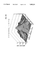
- FIG. 6A is a 3-D beam plot simulation of a 1 ⁇ 32 array with phase aberration
- FIG. 6B is a contour plot simulation of a 1 ⁇ 32 array with phase aberration
- FIG. 7A is a 3-D beam plot simulation of a 1 ⁇ 32 array with phase aberration and electronic phase correction in azimuth;
- FIG. 7B is a contour plot simulation of a 1 ⁇ 32 array with phase aberration and electronic phase correction in azimuth
- FIG. 8A is a 3-D beam plot simulation of a 1 ⁇ 32 array with phase aberration, electronic phase correction in azimuth, and mechanical phase correction in elevation;
- FIG. 8B is a contour plot simulation of a 1 ⁇ 32 array with phase aberration, electronic phase correction in azimuth, and mechanical phase correction in elevation;
- FIG. 9A is a 3-D beam plot simulation of a 2 ⁇ 32 array with phase aberration, electronic phase correction in azimuth, and mechanical phase correction in elevation;
- FIG. 9B is a contour plot simulation of a 2 ⁇ 32 array with phase aberration, electronic phase correction in azimuth, and mechanical phase correction in elevation;
- FIG. 10A is a 3-D beam plot simulation of a 4 ⁇ 32 array with phase aberration and electronic phase correction in azimuth and elevation;
- FIG. 10B is a contour plot simulation of 4 ⁇ 32 array with phase aberration and electronic phase correction in azimuth and elevation;
- FIG. 11 illustrates a 1 ⁇ 32 deformable array according to the present invention
- FIG. 12A illustrates the vector impedance of a typical PZT array element in air
- FIG. 12B illustrates the power spectrum of a typical PZT array element
- FIG. 13A illustrates measured and simulated azimuth beam plots with transducer in control position
- FIG. 13B illustrates measured and simulated elevation beam plots with transducer in control position
- FIG. 14A illustrates measured and simulated azimuth beam plots with the actuators tilted
- FIG. 14B illustrates measured and simulated elevation beam plots with the actuators tilted
- FIG. 15 illustrates a deformable array with actuators tilted at three different angles for three different depths of elevation focusing
- FIG. 16 illustrates a 3 ⁇ N deformable array.
- FIG. 1 illustrates a two-dimensional phased array transducer 5 with a two-dimensional aberrator 6 modeled as a subcutaneous fat layer of varying thickness.
- This array has four elements 7 in elevation; however, only eight elements 8 in azimuth are illustrated for simplicity.
- Uses for the transducer array illustrated in FIG. 1 include three dimensional ultrasound imaging or volumetric measurements and thin slice ultrasound imaging. See for example U.S. Pat. No. 5,311,095 to Smith et al., which is incorporated herein by reference in its entirety.
- FIGS. 2A and 2B a method of ultrasound phase correction by adjusting the electronic phase delay of the transducer array elements 15, is illustrated.
- the azimuth dimension is out of the paper, and the computed electronic delays used for elevation focusing are represented as ⁇ 1 - ⁇ 4 .
- the returning echoes 10 arrive at the transducer array elements 15 from an adjacent aberrating layer 6 and proceed to the summing amplifier ( ⁇ ) out of phase as shown in FIG. 2A.
- ⁇ summing amplifier
- FIGS. 3A and 3B An alternate method of phase correction by mechanically altering the physical location of transducer array elements 15 with actuators 16 is illustrated in FIGS. 3A and 3B.
- This technique is shown with the computed electronic delays for azimuth steering and focusing represented as ⁇ 1 and ⁇ 2 for a 2 ⁇ N array.
- Two transducer array elements are drawn in profile to show the elevation dimension in FIG. 3A.
- the transducer array element 15 size in elevation is large enough that the effect of the aberrator 6 is averaged in elevation; therefore, the transducer array elements cannot be used to correct phase aberrations in elevation by simply adjusting ⁇ 1 and ⁇ 2 .
- FIG. 3A shows the transducer 5 without phase correction. The elements are not moved, and the returning echoes 10 are not in phase.
- the transducer array elements 15 can be mechanically tilted in elevation.
- FIG. 3B shows the transducer array elements 15 tilted in elevation to compensate for the aberrating tissue 6, and the returning echoes 10 are now in phase.
- phase correction in azimuth is accomplished by altering the electronic phase delay of the transducer array elements 15.
- phase correction in elevation is accomplished by tilting the transducer array elements 15 in elevation with an actuator 16. Tilting the transducer array elements 15 in elevation will only remove the linear component, or the steering error, of the phase error in elevation. Since this technique is capable of removing the steering error from each transducer array element 15, the technique eliminates the problem of adjacent azimuthal transducer array elements steering in different elevation directions.
- a deformable transducer array of 1 ⁇ 128 (128 elements) or 2 ⁇ 128 (256 elements) approaches phase correction image quality of a more densely sampled two-dimensional array, for example, an array of 4 ⁇ 128 elements or more.
- the deformable array is illustrated for a transducer array 20 of 2 elements 15 in elevation by 32 elements 15 in azimuth.
- the 2 ⁇ 32 transducer is mounted on an array of low frequency piezoelectric actuators 16.
- every four transducer array elements 15 in azimuth are mounted on one independently controlled actuator 16 capable of tilting the elements in elevation. Since the actuators 16 must alter the element 15 position in elevation, they are mounted on a central pedestal 17 with eight actuators mounted as cantilevers on either side of the pedestal.
- the cantilevered end 16a of each actuator 16 is capable of moving up and down in the axial direction, thereby altering the transducer array element 15 position in elevation.
- the transducer array 20 By mounting the transducer array 20 on a substrate of actuators 16, the transducer array 20 is deformable in elevation.
- a two-dimensional correction may be implemented by tilting the transducer array elements 15 in elevation for the elevation phase correction, and by adjusting the electronic phase delay of the elements for the azimuth phase correction.
- phase correction process for the array shown in FIG. 4 was modeled using a broadband simulation based on the method of Stepanishen, (The Journal of the Acoustical Society of America, vol. 49, 841-849, 1971), using software developed by Jensen et al., (IEEE Transactions on Ultrasonics Ferroelectrics, and Frequency Control 39, 262-267, 1992). Simulated beam plots were used to assess and compare the radiation patterns of transducers with and without the presence of phase aberration. In addition to the beam plots, B-scan images of anechoic cysts embedded in tissue were simulated (not shown). Each scan line was created by the complex summation of the backscattered signal from a volume of randomly placed point scatterers with an average of 15 scatterers per resolution volume.
- a spherical void in the center of the volume with a diameter of 5 mm represented the cyst.
- the transducer was then incrementally scanned a distance of 20 mm in the azimuth direction at 0.25 mm increments and the resultant radio frequency (rf) lines were detected by Hilbert transform and displayed as a gray scale image.
- phase aberration data measured in vivo by Freiburger et al., (Ultrason. Imaging 14, 398-414, 1992), in human breast (interpolated to yield 197 MHz sampling) was used to degrade beam plots generated with the broad band simulation program.
- the aberrator was assumed to be a thin phase screen located near the transducer. Due to the undersampling of the measured aberrator in elevation, the data was interpolated using MATLAB (The Math Works, Inc., Natick, Mass.), resulting in 0.67 samples/mm.
- phased array transducer (10.5 mm in elevation by 16 mm in azimuth with a kerf of 0.087 mm, a 3.5 MHz center frequency, a 70 mm focus, and a Gaussian pulse with 60% -6 dB bandwidth) were compared for the following cases:
- phase correction techniques were evaluated by examining the largest -6 dB and -18 dB beam widths and respective rms phase error as summarized in Table 1 below.
- the beam plot and contour map shown in FIGS. 5A and 5B, respectively, were generated without the aberrator applied and represent the control case of an idealized array.
- the -6 dB and -18 dB worst case beam widths were 2.6 mm and 4.6 mm, respectively, for the control beam plot.
- the beam plot and contour map for the same array with the aberrator added are illustrated in FIGS. 6A and 6B, respectively.
- the average rms error of the aberrator was 77.7 ns (including the planar component) and the aberration disrupts the main beam and increases the side lobe level of the beam plot.
- the worst case aberrated beam widths were 4.6 mm at -6 dB and 9.2 mm at -18 dB.
- the azimuth aberrator was removed by subtracting the average aberration over the elevation dimension for each element leaving a residual rms error of 47.9 ns.
- Approximating the aberrator as a quadratic polynomial, ⁇ (x,y), the aberrator is:
- FIGS. 7A and 7B The beam plot and contour map for a 1 ⁇ 32 array when phase correction was applied only in azimuth are illustrated in FIGS. 7A and 7B, respectively.
- the main beam of the beam plot has been restored to a more regular shape.
- the beam plot is still severely degraded compared to the control beam plot (FIG. 5A).
- the worst case beam widths at -6 dB and -18 dB were 3.7 mm and 8.1 mm, respectively.
- FIGS. 8A and 8B The beam plot and contour map for a 1 ⁇ 32 deformable array when electronic phase aberration was applied in azimuth and the elements were mechanically tilted in elevation with each element pivoted about one end are illustrated in FIGS. 8A and 8B, respectively.
- removing the linear component of the aberrator in elevation in addition to removing the azimuth component would result in a residual phase aberration represented by:
- the -6 dB and -18 dB worst case beam widths were 2.8 mm and 5.0 mm, respectively.
- the main beam of the beam plot exhibits this improvement; however, the side lobe level is still increased.
- FIGS. 9A and 9B The beam plot and contour map for a 2 ⁇ 32 deformable array where the linear component of the aberrator was removed in elevation to simulate mechanically tilting each element in elevation and electronic phase correction was applied in azimuth are illustrated in FIGS. 9A and 9B, respectively.
- a 2 ⁇ 32 transducer approximates the quadratic elevation aberration by two piecewise linear components that leave some smaller error in the quadratic term represented by the coefficient f such that:
- the beam plot and contour map illustrated in FIGS. 10A and 10B, respectively, are the results of a 4 by 32 array with electronic phase correction applied in two dimensions leaving a residual rms error of 14.5 ns. With an ideal, finely sampled two-dimensional array, the aberrator is completely removed leaving:
- the beam plot and contour map are very similar to the control beam plot and contour map illustrated in FIGS. 5A and 5B, respectively.
- the -6 dB and -18 dB worst case beam widths were 2.6 mm and 4.6 mm just as for the control case.
- the transducer 20 is comprised of a plurality piezoelectric transducer elements 26 sandwiched between matching layers 25 and acoustically attenuating layers 18, and connected to actuators 16.
- the matching layers 25 are bonded to the piezoelectric transducer elements 26.
- the transducer elements 26 are also bonded to the upper surfaces 18a of the acoustically attenuating layers 18.
- the acoustically attenuating layers 18 are bonded to the actuators 16.
- Chips of known piezoelectric transducer materials of high acoustic impedance are suitable for use in the present invention; however, lead zircanate titanate (PZT) is preferred.
- PZT lead zircanate titanate
- the lower surface of each piezoelectric transducer element 26 is connected to the upper surface 18a of an acoustically attenuating layer 18.
- the attenuating layer 18 provides an electrical connection to the piezoelectric transducer elements 26 as well as the mechanical connection between the piezoelectric transducer elements 26 and the actuator 16.
- the thickness of the attenuating layer 18 is typically 0.1-10.0 mm and is made of epoxy with conductive or non-conductive fillers such as tungsten particles, tungsten oxide particles, aluminum oxide particles, phenolic balloon scatterers, glass balloon scatterers, rubber scatterers, and silicone scatterers with ranges of 1-100 microns.
- conductive or non-conductive fillers such as tungsten particles, tungsten oxide particles, aluminum oxide particles, phenolic balloon scatterers, glass balloon scatterers, rubber scatterers, and silicone scatterers with ranges of 1-100 microns.
- a matching layer 25 is connected to the upper surface of each piezoelectric transducer element 26.
- the thickness of the matching layer 25 is preferably one fourth the wavelength ( ⁇ /4) of the frequency of operation of the transducer 20 and is referred to as the ⁇ /4 matching layer.
- the matching layer 25 may be made of the same materials as the attenuating layer 18.
- the transducer 20 comprises a RAINBOW (Reduced And Internally Biased Oxide Wafer) actuator 16 (developed by Haertling et al. at Clemson University and manufactured by Aura Ceramics, Inc., part #C3900, New Hope, Minn.).
- a RAINBOW actuator is a piezoelectric ceramic that has been chemically reduced on one side.
- a RAINBOW mounted as a cantilever produces deflection at the free end when an electric field is applied to electrodes connected thereto.
- the RAINBOWs generate greater displacement than bimorphs with the same voltage. For example, a ⁇ 1° deflection is possible for a sample 12 mm in length at ⁇ 150 volts. Due to stresses that form during fabrication, the RAINBOWs may become slightly curved.
- FIG. 11 only two actuators 16 and eight PZT transducer array elements 26 are shown in the azimuth direction, for simplicity.
- Electrical connection to the transducer array elements 26 and the actuators 16 is made by a flexible polyimide, such as KAPTON® (a trademark of the E. I. DuPont de Nemours Company, Wilmington, Del.), connector 18.
- KAPTON® a trademark of the E. I. DuPont de Nemours Company, Wilmington, Del.
- a mask for photolithography was designed, a piece of polyimide which was sputtered with chrome and gold was exposed to u.v. light, the photoresist was developed, and the metal was etched to form the electrode pattern.
- the flexible connector 18 reduces reverberations between the PZT transducer elements 26 and the actuators 16.
- the actuator deflection is dependent on the voltage applied. Since each actuator 16 must deflect independently, a separate voltage must be applied to each actuator.
- a phase correction algorithm such as the speckle brightness method described by Nock et al. (The Journal of the Acoustical Society of America, vol. 85, 1819-1833, 1989), or the correlation method described by Flax et al. (IEEE Transactions on Ultrasonics, Ferroelectrics, and Frequency Control, vol. 35, 758-767, 1988), the amount of voltage necessary to tilt the actuator 16 will be determined. Specifically for the speckle brightness method described by Nock et al., the brightness of a chosen region of interest is calculated.
- the actuator tilt is modified and the brightness of the region recomputed for the same region of interest. This process is repeated until the speckle brightness is maximized for the region of interest.
- the actuator position of the brightest calculation is the phase corrected position. By repeating the procedure for each actuator 16, the corrected elevation position is found.
- each actuator 16 should be able to tilt ⁇ 1°; each actuator should have a frequency response of at least 1 KHz for high speed phase correction; and the total length of each actuator should be less than 12 mm for scanning with a restricted acoustic window.
- a deformable array is assembled as follows.
- a ⁇ /4 epoxy (Ciba Geigy, Hawthorn, N.Y.) matching layer is bonded to a PZT transducer chip, preferably a 0.33 mm thick HD3203 from Motorola Ceramics (Albuquerque, N.M.), using the Papadakis method (Journal of Adhesion 3, 181-194, 1971).
- the bonded matching layer and transducer chip are approximately square, having dimensions of 0.5 inch by 0.5 inch.
- the bonded PZT transducer chip and matching layer are then bonded to the flexible polyimide connector with silver epoxy (Chomerics 584, Woburn, Mass.) using a bonding jig (Logitek, Greensboro, N.C.).
- the array is diced with a dicing saw, for example, a model 782 Kulicke & Soffa or equivalent (Willow Grove, Pa.) into linear array elements 26 having dimensions of approximately 0.318 mm by 12.7 mm (0.0125" by 0.5") with a 0.1 mm kerf.
- the dicing saw cuts completely through the matching layer 25 and transducer chip 26, and partly through the flexible connector 18.
- a 0.152 mm silver ribbon (not shown) such as the type manufactured by Sigmund-Cohn (Mr. Vernon, N.Y.) is stitched by wire bonding across all of the elements 26 of the array to provide grounding using a wire bonder such as a Hughes Wire Bonder model MCW-550 (Carlsbad, Calif.) or equivalent. Silver ribbons are also aligned and secured to the backside of the polyimide connector 18 with cyanoacrylate.
- the base member 17 is drilled with ten holes (not shown) at a spacing of 1.27 mm. Eight of the holes provide electrical connection to the bottom electrode (not shown) of the actuator 16; the remaining two holes serve as guidance marks.
- the holes are filled with silver epoxy, and then wires 30 are inserted into the holes.
- each actuator 16 is bonded to the base member 17.
- the bonded PZT transducer chip, matching layer, and flexible connector are then bonded to an actuator 16, which has a portion secured to a base member with silver epoxy to make the electrical connection from the actuator top electrode (not shown) to the silver ribbons on the backside of the polyimide.
- Each actuator 16 typically has dimensions of approximately 1 inch in length by 0.5 inches in width.
- the array is diced again to physically separate the actuator into 8 individual actuators 16, each with 4 linear array elements 26.
- the dicing saw is lined up to cut in the kerf of the linear array elements 26. A cut is made between every four array elements 26 to produce 32 linear array elements divided between 8 actuators 16.
- Indium solder preferably Indalloy #2 (Indium Corporation of America, Utica, N.Y.) is used to connect 0.254 mm silver wires of the type manufactured by Sigmund-Cohn (Mr. Vernon, N.Y.) to the electrodes of the polyimide connector 18. These wires are soldered to a connector for the transducer handle (not shown) which interfaces with a Siemens 1200 phased array scanner, and the actuator wires are soldered to a separate connector to provide the actuator control. The final step is to cover any exposed wiring with copper tape for electrical shielding.
- a base unit for controlling the actuators and for supplying power to the transducer elements is typically provided in an independent housing, as would be understood by those having skill in the art. See, for example, U.S. Pat. No. 5,419,329 to Smith et al., which is incorporated herein by reference in its entirety.
- An elevation lens may be used to focus the ultrasound beam in elevation.
- Acoustically transparent material should be used in the transducer housing for contact with the patient.
- a non-conductive, low-attenuation fluid should be used in the transducer housing for high frequency transducers.
- the performance of single elements of the transducer was assessed by examining the vector impedance, the pulse-echo response, and the pulse-echo bandwidth. Also examined was the array performance with measured pulse-echo beam plots.
- the vector impedance of individual array elements was measured using a Hewlett-Packard 4193A Vector Impedance Meter. Each vector impedance measurement was completed in air to determine the element resonance and the presence of undesired modes of vibration.
- the pulse-echo sensitivity and the pulse-echo bandwidth measurements were made in vegetable oil since that was the medium used for imaging.
- the actuator control voltage can be as much as 300 volts DC. Therefore, the apparatus was not immersed in water since the high DC control voltages would allow conduction through the water. Instead, oil, which has a much lower conductivity, was used as the sound transmission medium.
- the pulse-echo sensitivity from a block at a range of 6 cm was measured using a Metrotek Model 215 Transmitter to generate a 200 V spike, and the return echo was received with a Model 101 Receiver.
- the power spectrum was measured using a Panametrics 5052G Stepless Gate and a Hewlett-Packard 3588A Spectrum Analyzer.
- One dimensional azimuth and elevation translation beam plots in oil were also measured.
- a 1.5 mm rod ground to a hemispherical cap was used as the point target which was manually scanned to acquire the beam plot.
- the rod was scanned a total of 20 mm at 0.5 mm increments.
- the maximum voltage of the rf sum was recorded from the Siemens 1200 beam-former. This procedure was used to obtain beam plots in azimuth and elevation for two conditions. The first set was measured with the actuators in the normal or co-planar position. For the second set of beam plots, actuators 2, 3, 6, and 8 were tilted 1°.
- Simulated beam plots were generated with the broad band simulation program developed by Jensen et al., (IEEE Transactions on Ultrasonics, Ferroelectrics, and Frequency Control, vol. 39, 262-267, 1992), under equivalent conditions as the measured beam plots for comparison.
- FIG. 12A illustrates the vector impedance of a typical PZT array element of the deformable transducer in air.
- the resonance at 3.5 MHz is due to the epoxy matching layer.
- the double peaked resonance at 5 MHz is interaction of the resonance of the PZT element and the actuator.
- the flexible connector does not eliminate the possibility of sound resonating in the actuator.
- the only other mode visible in the impedance plot is a slight width mode at 9.5 MHz.
- the associated spectrum, FIG. 12B is shown for the same single element of the transducer.
- the -6 dB width of the element is 60% which was typical for the array.
- FIGS. 13A and 13B the measured and simulated pulse-echo beam plots for the deformable transducer when the actuators were in the control or co-planar position are illustrated. Since the deformable transducer array was unfocused in elevation, the beam plots were measured and simulated at a depth of 11 cm to be in the far field of the elevation dimension.
- FIG. 13A compares the measured and simulated azimuth one dimensional beam plots with the deformable transducer in the control position.
- the -6 dB beam width is 6.25 mm for the measured beam plot in azimuth and 6.5 mm for the simulated beam plot in azimuth.
- the 13B compare the measured and simulated elevation beam plots when actuators were in the control position.
- the -6 dB beam width is 5.25 mm for the measured elevation beam plot and 5.0 mm for the simulated elevation beam plot. Both the azimuth and elevation measured beam plots agree well with the simulated azimuth and elevation beam plots.
- FIGS. 14A and 14B the measured and simulated beam plots when actuators 2, 3, 6, and 8 were tilted 1°, are illustrated.
- FIG. 14A compares the measured and simulated azimuth beam plots with the actuators tilted. In azimuth, the -6 dB beam width is 6.75 mm for the measured beam plot and 7.25 mm for the simulated beam plot.
- FIG. 14B compares the measured and simulated elevation beam plots with the actuators tilted.
- the measured -6 dB beam width in elevation is 7.5 mm
- the simulated beam width in elevation is 5.25 mm.
- the measured azimuth and elevation beam plots with actuators 2, 3, 6, and 8 tilted are in reasonable agreement with the simulated azimuth and elevation beam plots.
- a simpler 1 ⁇ N or 2 ⁇ N deformable array can approach the image quality of an array of 4 ⁇ N elements or greater.
- Mechanically tilting the elements only partially corrects phase aberrations since it removes the linear component, or the steering error, of the phase aberration. That means that tilting the elements in elevation eliminates the problem of adjacent azimuthal elements steering in different directions.
- a phased array scanner incorporating a 1 ⁇ N or 2 ⁇ N deformable transducer is lower in cost and simpler than a full M x N two-dimensional array, yet significantly improves ultrasound image quality.
- the ultrasound beam from a conventional linear array can be electronically focused in azimuth which allows the depth of the azimuth focus to be altered on-line.
- a mechanical lens is used to focus the beam at a fixed depth in elevation.
- the deformable array according to the present invention is not limited by a fixed elevation focus.
- the transmit elevation focus can be adjusted on-line with a push of a button.
- the actuators can be tilted at a specific angle to focus the ultrasound beam at a single depth.
- a more desirable option would be to implement dynamic receive focusing with the actuators.
- continuous dynamic receive focusing could be implemented.
- the control signal would continuously match the elevation focus, or the tilt of the actuators, to the depth of the returning echo.
- Continuous dynamic receive focusing would require the actuators to respond in looks for a typical scan depth of 150 mm.
- the RAINBOW actuators may be curved as a result of stresses induced during fabrication.
- the curvature would improve the ability of the transducer to focus the ultrasound beam in elevation since the curvature is a better match to the desired spherical focus.
- the deformable array is not limited to a 1 ⁇ N or 2 ⁇ N design. Additional more complicated configurations are also possible such as the 3 ⁇ N design illustrated in FIG. 16.
Abstract
Description
              TABLE 1
______________________________________
                   WORST CASE
                   BEAM      RMS
                   WIDTHS    PHASE
                     -6 dB   -18 dB  ERROR
SIMULATION           (mm)    (mm)    (ns)
______________________________________
Control              2.6     4.6     0
Aberrated            4.6     9.2     77.7
Electronic Phase Correction
                     3.7     8.1     47.9
in Azimuth
1 × 32 Array
Electronic Phase Correction in Azimuth
                     2.8     5.0     25.4
and Mechanical Correction in Elevation
1 × 32 Array
Electronic Phase Correction in Azimuth
                     2.6     4.6     20.4
and Mechanical Correction in Elevation
2 × 32 Array
Electronic Phase Correction in Two
                     2.6     4.6     14.5
Dimensions with a
4 × 32 Array
______________________________________
ψ(x,y)=A+Bx+Cy+Dx.sup.2 +Exy+Fy.sup.2
ψ'(x,y)=Cy+Exy+Fy.sup.2
ψ"(x,y)=Exy+Fy.sup.2
ψ"'(x,y)=Exy+fy.sup.2
ψ""(x,y)≈0
Claims (26)
Priority Applications (1)
| Application Number | Priority Date | Filing Date | Title |
|---|---|---|---|
| US08/467,003 US5605154A (en) | 1995-06-06 | 1995-06-06 | Two-dimensional phase correction using a deformable ultrasonic transducer array |
Applications Claiming Priority (1)
| Application Number | Priority Date | Filing Date | Title |
|---|---|---|---|
| US08/467,003 US5605154A (en) | 1995-06-06 | 1995-06-06 | Two-dimensional phase correction using a deformable ultrasonic transducer array |
Publications (1)
| Publication Number | Publication Date |
|---|---|
| US5605154A true US5605154A (en) | 1997-02-25 |
Family
ID=23853956
Family Applications (1)
| Application Number | Title | Priority Date | Filing Date |
|---|---|---|---|
| US08/467,003 Expired - Fee Related US5605154A (en) | 1995-06-06 | 1995-06-06 | Two-dimensional phase correction using a deformable ultrasonic transducer array |
Country Status (1)
| Country | Link |
|---|---|
| US (1) | US5605154A (en) |
Cited By (94)
| Publication number | Priority date | Publication date | Assignee | Title |
|---|---|---|---|---|
| US5865751A (en) * | 1996-06-11 | 1999-02-02 | Olympus Optical Co., Ltd. | Ultrasonic diagnostic apparatus which performs complex vector phase correction to echo signals obtained in time sequence from each ultrasonic transducer |
| US5906580A (en) * | 1997-05-05 | 1999-05-25 | Creare Inc. | Ultrasound system and method of administering ultrasound including a plurality of multi-layer transducer elements |
| US5938612A (en) * | 1997-05-05 | 1999-08-17 | Creare Inc. | Multilayer ultrasonic transducer array including very thin layer of transducer elements |
| US6168565B1 (en) * | 1999-03-31 | 2001-01-02 | Acuson Corporation | Medical diagnostic ultrasound system and method for simultaneous phase correction of two frequency band signal components |
| US6231511B1 (en) * | 1997-11-10 | 2001-05-15 | Medison Co., Ltd. | Ultrasonic signal focusing method and apparatus for ultrasonic imaging system |
| US20010041837A1 (en) * | 2000-02-07 | 2001-11-15 | Takashi Takeuchi | Ultrasonic probe and method of manufacturing the same |
| US20020018508A1 (en) * | 1998-04-16 | 2002-02-14 | Ramesh Sundaram | Glide head for asperity detection |
| US6360428B1 (en) * | 1998-04-16 | 2002-03-26 | Seagate Technology Llc | Glide heads and methods for making glide heads |
| US20020132858A1 (en) * | 2001-01-22 | 2002-09-19 | Orion Corporation | Method for treating sexual disorders |
| US6454716B1 (en) * | 2000-05-23 | 2002-09-24 | P.M.G. Medica Ltd. | System and method for detection of fetal heartbeat |
| US20030004439A1 (en) * | 1999-02-02 | 2003-01-02 | Transurgical, Inc. | Intrabody HIFU applicator |
| US6508764B1 (en) | 2000-10-31 | 2003-01-21 | Koninklijke Philips Electronics N.V. | Aberration correction apparatus and methods |
| US6607489B2 (en) * | 2001-04-05 | 2003-08-19 | General Electric Company | Focus correction for ultrasound imaging through mammography compression plate |
| US6612988B2 (en) * | 2000-08-29 | 2003-09-02 | Brigham And Women's Hospital, Inc. | Ultrasound therapy |
| US6656124B2 (en) * | 2001-10-15 | 2003-12-02 | Vermon | Stack based multidimensional ultrasonic transducer array |
| US20040122323A1 (en) * | 2002-12-23 | 2004-06-24 | Insightec-Txsonics Ltd | Tissue aberration corrections in ultrasound therapy |
| US6770031B2 (en) | 2000-12-15 | 2004-08-03 | Brigham And Women's Hospital, Inc. | Ultrasound therapy |
| US20040242999A1 (en) * | 2003-06-02 | 2004-12-02 | Shuki Vitek | Endo-cavity focused ultrasound transducer |
| US20050020918A1 (en) * | 2000-02-28 | 2005-01-27 | Wilk Ultrasound Of Canada, Inc. | Ultrasonic medical device and associated method |
| US20050049496A1 (en) * | 2003-09-03 | 2005-03-03 | Siemens Medical Solutions Usa, Inc. | Motion artifact reduction in coherent image formation |
| US20050148899A1 (en) * | 2003-10-22 | 2005-07-07 | Walker William F. | Method and apparatus for characterization of clot formation |
| US20060064081A1 (en) * | 2004-09-13 | 2006-03-23 | Michael Rosinko | Ablation device with phased array ultrasound transducer |
| US20070016039A1 (en) * | 2005-06-21 | 2007-01-18 | Insightec-Image Guided Treatment Ltd. | Controlled, non-linear focused ultrasound treatment |
| US20070142727A1 (en) * | 2005-12-15 | 2007-06-21 | Cardiac Pacemakers, Inc. | System and method for analyzing cardiovascular pressure measurements made within a human body |
| US20070167765A1 (en) * | 2005-11-18 | 2007-07-19 | Imarx Therapeutics, Inc. | Ultrasound emitting device comprising a head frame |
| US20070167781A1 (en) * | 2005-11-23 | 2007-07-19 | Insightec Ltd. | Hierarchical Switching in Ultra-High Density Ultrasound Array |
| US20080082026A1 (en) * | 2006-04-26 | 2008-04-03 | Rita Schmidt | Focused ultrasound system with far field tail suppression |
| US20090088623A1 (en) * | 2007-10-01 | 2009-04-02 | Insightec, Ltd. | Motion compensated image-guided focused ultrasound therapy system |
| US20090112094A1 (en) * | 2006-04-13 | 2009-04-30 | The Research Foundation Of State University Of New York | Phased Apply Ultrasound With Electronically Controlled Focal Point For Assessing Bone Quality Via Acoustic Topology And Wave Transmit Functions |
| US20090201148A1 (en) * | 2008-02-12 | 2009-08-13 | Tran Binh C | Systems and methods for controlling wireless signal transfers between ultrasound-enabled medical devices |
| US20100030076A1 (en) * | 2006-08-01 | 2010-02-04 | Kobi Vortman | Systems and Methods for Simultaneously Treating Multiple Target Sites |
| US20100056962A1 (en) * | 2003-05-22 | 2010-03-04 | Kobi Vortman | Acoustic Beam Forming in Phased Arrays Including Large Numbers of Transducer Elements |
| US20100125193A1 (en) * | 2008-11-19 | 2010-05-20 | Eyal Zadicario | Closed-Loop Clot Lysis |
| US20100179425A1 (en) * | 2009-01-13 | 2010-07-15 | Eyal Zadicario | Systems and methods for controlling ultrasound energy transmitted through non-uniform tissue and cooling of same |
| US20100228130A1 (en) * | 2009-03-09 | 2010-09-09 | Teratech Corporation | Portable ultrasound imaging system |
| US20100268088A1 (en) * | 2009-04-17 | 2010-10-21 | Oleg Prus | Multimode ultrasound focusing for medical applications |
| US20100274138A1 (en) * | 2008-11-28 | 2010-10-28 | Olympus Medical Systems Corp. | Ultrasound transducer, electronic device and ultrasound endoscope |
| US20100318002A1 (en) * | 2009-06-10 | 2010-12-16 | Oleg Prus | Acoustic-Feedback Power Control During Focused Ultrasound Delivery |
| US20110034800A1 (en) * | 2009-08-04 | 2011-02-10 | Shuki Vitek | Estimation of alignment parameters in magnetic-resonance-guided ultrasound focusing |
| US20110046475A1 (en) * | 2009-08-24 | 2011-02-24 | Benny Assif | Techniques for correcting temperature measurement in magnetic resonance thermometry |
| US20110046472A1 (en) * | 2009-08-19 | 2011-02-24 | Rita Schmidt | Techniques for temperature measurement and corrections in long-term magnetic resonance thermometry |
| US20110066032A1 (en) * | 2009-08-26 | 2011-03-17 | Shuki Vitek | Asymmetric ultrasound phased-array transducer |
| US20110109309A1 (en) * | 2009-11-10 | 2011-05-12 | Insightec Ltd. | Techniques for correcting measurement artifacts in magnetic resonance thermometry |
| US20120165670A1 (en) * | 2009-09-03 | 2012-06-28 | Koninklijke Philips Electronics N.V. | Contralateral array based correction of transcranial ultrasound aberration |
| USRE43901E1 (en) | 2000-11-28 | 2013-01-01 | Insightec Ltd. | Apparatus for controlling thermal dosing in a thermal treatment system |
| US8409099B2 (en) | 2004-08-26 | 2013-04-02 | Insightec Ltd. | Focused ultrasound system for surrounding a body tissue mass and treatment method |
| US8591423B2 (en) | 2008-10-10 | 2013-11-26 | Cardiac Pacemakers, Inc. | Systems and methods for determining cardiac output using pulmonary artery pressure measurements |
| US8632470B2 (en) | 2008-11-19 | 2014-01-21 | Cardiac Pacemakers, Inc. | Assessment of pulmonary vascular resistance via pulmonary artery pressure |
| US8661873B2 (en) | 2009-10-14 | 2014-03-04 | Insightec Ltd. | Mapping ultrasound transducers |
| US8725260B2 (en) | 2008-02-11 | 2014-05-13 | Cardiac Pacemakers, Inc | Methods of monitoring hemodynamic status for rhythm discrimination within the heart |
| US8932237B2 (en) | 2010-04-28 | 2015-01-13 | Insightec, Ltd. | Efficient ultrasound focusing |
| US9031701B2 (en) | 2011-02-15 | 2015-05-12 | Hemosonics Llc | Characterization of blood hemostasis and oxygen transport parameters |
| US20150214764A1 (en) * | 2011-05-27 | 2015-07-30 | uBeam, Inc. | Steering for wireless power transfer |
| US20150333798A1 (en) * | 2011-05-27 | 2015-11-19 | uBeam Inc. | Oscillator circuits for wireless power transfer |
| US9272280B2 (en) | 2011-02-15 | 2016-03-01 | Hemosonics Llc | Device, systems and methods for evaluation of hemostasis |
| US20160361573A1 (en) * | 2004-10-06 | 2016-12-15 | Guided Therapy Systems, L.L.C. | Systems for treating skin laxity |
| US20160375274A1 (en) * | 2004-10-06 | 2016-12-29 | Guided Therapy Systems, Llc | Method and system for ultrasound treatment of skin |
| US9537322B2 (en) | 2011-05-27 | 2017-01-03 | uBeam Inc. | Sub-apertures with interleaved transmit elements for wireless power transfer |
| US20170087391A1 (en) * | 2004-10-06 | 2017-03-30 | Guided Therapy Systems, Llc | System and method for fat and cellulite reduction |
| US20170095680A1 (en) * | 2004-10-06 | 2017-04-06 | Guided Therapy Systems, Llc | Energy based fat reduction |
| US9726647B2 (en) | 2015-03-17 | 2017-08-08 | Hemosonics, Llc | Determining mechanical properties via ultrasound-induced resonance |
| US9819399B2 (en) | 2011-05-27 | 2017-11-14 | uBeam Inc. | Beam interaction control for wireless power transfer |
| US9831920B2 (en) | 2011-05-27 | 2017-11-28 | uBeam Inc. | Motion prediction for wireless power transfer |
| US9827449B2 (en) * | 2004-10-06 | 2017-11-28 | Guided Therapy Systems, L.L.C. | Systems for treating skin laxity |
| US9852727B2 (en) | 2010-04-28 | 2017-12-26 | Insightec, Ltd. | Multi-segment ultrasound transducers |
| US9895560B2 (en) | 2004-09-24 | 2018-02-20 | Guided Therapy Systems, Llc | Methods for rejuvenating skin by heating tissue for cosmetic treatment of the face and body |
| US9974982B2 (en) | 2004-10-06 | 2018-05-22 | Guided Therapy Systems, Llc | System and method for noninvasive skin tightening |
| US9981148B2 (en) | 2010-10-22 | 2018-05-29 | Insightec, Ltd. | Adaptive active cooling during focused ultrasound treatment |
| US10046181B2 (en) | 2004-10-06 | 2018-08-14 | Guided Therapy Systems, Llc | Energy based hyperhidrosis treatment |
| US10148131B2 (en) | 2011-05-27 | 2018-12-04 | uBeam Inc. | Power density control for wireless power transfer |
| US10147152B2 (en) | 2010-04-08 | 2018-12-04 | Hemosonics, Llc | Hemostatic parameter display |
| US10420960B2 (en) | 2013-03-08 | 2019-09-24 | Ulthera, Inc. | Devices and methods for multi-focus ultrasound therapy |
| US10517569B2 (en) | 2012-05-09 | 2019-12-31 | The Regents Of The University Of Michigan | Linear magnetic drive transducer for ultrasound imaging |
| US10537304B2 (en) | 2008-06-06 | 2020-01-21 | Ulthera, Inc. | Hand wand for ultrasonic cosmetic treatment and imaging |
| US10603521B2 (en) | 2014-04-18 | 2020-03-31 | Ulthera, Inc. | Band transducer ultrasound therapy |
| WO2020139775A1 (en) * | 2018-12-27 | 2020-07-02 | Exo Imaging, Inc. | Methods to maintain image quality in ultrasound imaging at reduced cost, size, and power |
| US10835209B2 (en) | 2016-12-04 | 2020-11-17 | Exo Imaging Inc. | Configurable ultrasonic imager |
| US10864385B2 (en) | 2004-09-24 | 2020-12-15 | Guided Therapy Systems, Llc | Rejuvenating skin by heating tissue for cosmetic treatment of the face and body |
| US10996230B2 (en) | 2008-12-23 | 2021-05-04 | C A Casyso Gmbh | Cartridge device for a measuring system for measuring viscoelastic characteristics of a sample liquid, a corresponding measuring system, and a corresponding method |
| US11054396B2 (en) | 2011-05-19 | 2021-07-06 | Hemosonics Llc | Hemostasis analyzer |
| US11199623B2 (en) | 2020-03-05 | 2021-12-14 | Exo Imaging, Inc. | Ultrasonic imaging device with programmable anatomy and flow imaging |
| US11207548B2 (en) * | 2004-10-07 | 2021-12-28 | Guided Therapy Systems, L.L.C. | Ultrasound probe for treating skin laxity |
| US11224895B2 (en) | 2016-01-18 | 2022-01-18 | Ulthera, Inc. | Compact ultrasound device having annular ultrasound array peripherally electrically connected to flexible printed circuit board and method of assembly thereof |
| US20220023671A1 (en) * | 2004-10-07 | 2022-01-27 | Guided Therapy Systems, Llc | Ultrasound probe for treatment of skin |
| US11235179B2 (en) | 2004-10-06 | 2022-02-01 | Guided Therapy Systems, Llc | Energy based skin gland treatment |
| US11241218B2 (en) | 2016-08-16 | 2022-02-08 | Ulthera, Inc. | Systems and methods for cosmetic ultrasound treatment of skin |
| US11327069B2 (en) | 2014-09-29 | 2022-05-10 | Ca Casyso Gmbh | Blood testing system and method |
| US11338156B2 (en) | 2004-10-06 | 2022-05-24 | Guided Therapy Systems, Llc | Noninvasive tissue tightening system |
| US11366093B2 (en) | 2017-04-20 | 2022-06-21 | Hemosonics, Llc | Disposable system for analysis of hemostatic function |
| US11883688B2 (en) | 2004-10-06 | 2024-01-30 | Guided Therapy Systems, Llc | Energy based fat reduction |
| US11898993B2 (en) | 2018-03-30 | 2024-02-13 | Labcyte, Inc. | Fluid impermeable ultrasonic transducer |
| US11911215B2 (en) | 2021-05-26 | 2024-02-27 | Siemens Medical Solutions Usa, Inc. | Ultrasound probe with adjustable aperture |
| US11944849B2 (en) | 2018-02-20 | 2024-04-02 | Ulthera, Inc. | Systems and methods for combined cosmetic treatment of cellulite with ultrasound |
| US11969609B2 (en) | 2022-12-05 | 2024-04-30 | Ulthera, Inc. | Devices and methods for multi-focus ultrasound therapy |
Citations (10)
| Publication number | Priority date | Publication date | Assignee | Title |
|---|---|---|---|---|
| US4434799A (en) * | 1982-03-02 | 1984-03-06 | Siemens Ag | Ultrasound apparatus for medical examinations |
| US4862892A (en) * | 1988-07-18 | 1989-09-05 | Sri International | Ultrasonic reflex transmission imaging method and apparatus with artifact removal |
| US4957099A (en) * | 1988-02-10 | 1990-09-18 | Siemens Aktiengesellschaft | Shock wave source for extracorporeal lithotripsy |
| US5166508A (en) * | 1991-09-20 | 1992-11-24 | United Technologies Corporation | Optical processor for controlling a deformable mirror |
| US5247222A (en) * | 1991-11-04 | 1993-09-21 | Engle Craig D | Constrained shear mode modulator |
| US5311095A (en) * | 1992-05-14 | 1994-05-10 | Duke University | Ultrasonic transducer array |
| US5329496A (en) * | 1992-10-16 | 1994-07-12 | Duke University | Two-dimensional array ultrasonic transducers |
| US5331964A (en) * | 1993-05-14 | 1994-07-26 | Duke University | Ultrasonic phased array imaging system with high speed adaptive processing using selected elements |
| US5419329A (en) * | 1994-06-03 | 1995-05-30 | Duke University | Optoelectronic transmitters for medical ultrasound transducers |
| US5438554A (en) * | 1993-06-15 | 1995-08-01 | Hewlett-Packard Company | Tunable acoustic resonator for clinical ultrasonic transducers |
-
1995
- 1995-06-06 US US08/467,003 patent/US5605154A/en not_active Expired - Fee Related
Patent Citations (10)
| Publication number | Priority date | Publication date | Assignee | Title |
|---|---|---|---|---|
| US4434799A (en) * | 1982-03-02 | 1984-03-06 | Siemens Ag | Ultrasound apparatus for medical examinations |
| US4957099A (en) * | 1988-02-10 | 1990-09-18 | Siemens Aktiengesellschaft | Shock wave source for extracorporeal lithotripsy |
| US4862892A (en) * | 1988-07-18 | 1989-09-05 | Sri International | Ultrasonic reflex transmission imaging method and apparatus with artifact removal |
| US5166508A (en) * | 1991-09-20 | 1992-11-24 | United Technologies Corporation | Optical processor for controlling a deformable mirror |
| US5247222A (en) * | 1991-11-04 | 1993-09-21 | Engle Craig D | Constrained shear mode modulator |
| US5311095A (en) * | 1992-05-14 | 1994-05-10 | Duke University | Ultrasonic transducer array |
| US5329496A (en) * | 1992-10-16 | 1994-07-12 | Duke University | Two-dimensional array ultrasonic transducers |
| US5331964A (en) * | 1993-05-14 | 1994-07-26 | Duke University | Ultrasonic phased array imaging system with high speed adaptive processing using selected elements |
| US5438554A (en) * | 1993-06-15 | 1995-08-01 | Hewlett-Packard Company | Tunable acoustic resonator for clinical ultrasonic transducers |
| US5419329A (en) * | 1994-06-03 | 1995-05-30 | Duke University | Optoelectronic transmitters for medical ultrasound transducers |
Non-Patent Citations (3)
| Title |
|---|
| Hardy; Adaptive Optics; Scientific American; Jun. 1994; pp. 60 65. * |
| Hardy; Adaptive Optics; Scientific American; Jun. 1994; pp. 60-65. |
| Ries et al.; Phase Aberration Correction in Two Dimensions Using a Deformable Array Transducer; Ultrasonic Imaging, vol. 17, No. 1; Jan. 1995; p. 62. * |
Cited By (207)
| Publication number | Priority date | Publication date | Assignee | Title |
|---|---|---|---|---|
| US20080228077A1 (en) * | 1992-01-10 | 2008-09-18 | Wilk Ultrasound Of Canada, Inc. | Ultrasonic medical device and associated method |
| US8235907B2 (en) * | 1992-01-10 | 2012-08-07 | Wilk Ultrasound of Canada, Inc | Ultrasonic medical device and associated method |
| US5865751A (en) * | 1996-06-11 | 1999-02-02 | Olympus Optical Co., Ltd. | Ultrasonic diagnostic apparatus which performs complex vector phase correction to echo signals obtained in time sequence from each ultrasonic transducer |
| US5906580A (en) * | 1997-05-05 | 1999-05-25 | Creare Inc. | Ultrasound system and method of administering ultrasound including a plurality of multi-layer transducer elements |
| US5938612A (en) * | 1997-05-05 | 1999-08-17 | Creare Inc. | Multilayer ultrasonic transducer array including very thin layer of transducer elements |
| US6231511B1 (en) * | 1997-11-10 | 2001-05-15 | Medison Co., Ltd. | Ultrasonic signal focusing method and apparatus for ultrasonic imaging system |
| US6899456B2 (en) | 1998-04-16 | 2005-05-31 | Seagate Technology Llc | Glide head for asperity detection |
| US20020018508A1 (en) * | 1998-04-16 | 2002-02-14 | Ramesh Sundaram | Glide head for asperity detection |
| US6360428B1 (en) * | 1998-04-16 | 2002-03-26 | Seagate Technology Llc | Glide heads and methods for making glide heads |
| US6891698B2 (en) | 1998-04-16 | 2005-05-10 | Seagate Technology Llc | Wafer having surface contoured to form air bearing surfaces of a plurality of glide heads |
| US20030004439A1 (en) * | 1999-02-02 | 2003-01-02 | Transurgical, Inc. | Intrabody HIFU applicator |
| US6168565B1 (en) * | 1999-03-31 | 2001-01-02 | Acuson Corporation | Medical diagnostic ultrasound system and method for simultaneous phase correction of two frequency band signal components |
| US20010041837A1 (en) * | 2000-02-07 | 2001-11-15 | Takashi Takeuchi | Ultrasonic probe and method of manufacturing the same |
| US7288069B2 (en) * | 2000-02-07 | 2007-10-30 | Kabushiki Kaisha Toshiba | Ultrasonic probe and method of manufacturing the same |
| US7597665B2 (en) * | 2000-02-28 | 2009-10-06 | Wilk Peter J | Ultrasonic medical device and associated method |
| US20050020918A1 (en) * | 2000-02-28 | 2005-01-27 | Wilk Ultrasound Of Canada, Inc. | Ultrasonic medical device and associated method |
| US6454716B1 (en) * | 2000-05-23 | 2002-09-24 | P.M.G. Medica Ltd. | System and method for detection of fetal heartbeat |
| US6612988B2 (en) * | 2000-08-29 | 2003-09-02 | Brigham And Women's Hospital, Inc. | Ultrasound therapy |
| US6508764B1 (en) | 2000-10-31 | 2003-01-21 | Koninklijke Philips Electronics N.V. | Aberration correction apparatus and methods |
| USRE43901E1 (en) | 2000-11-28 | 2013-01-01 | Insightec Ltd. | Apparatus for controlling thermal dosing in a thermal treatment system |
| US6770031B2 (en) | 2000-12-15 | 2004-08-03 | Brigham And Women's Hospital, Inc. | Ultrasound therapy |
| US20020132858A1 (en) * | 2001-01-22 | 2002-09-19 | Orion Corporation | Method for treating sexual disorders |
| US6607489B2 (en) * | 2001-04-05 | 2003-08-19 | General Electric Company | Focus correction for ultrasound imaging through mammography compression plate |
| US6656124B2 (en) * | 2001-10-15 | 2003-12-02 | Vermon | Stack based multidimensional ultrasonic transducer array |
| US8088067B2 (en) | 2002-12-23 | 2012-01-03 | Insightec Ltd. | Tissue aberration corrections in ultrasound therapy |
| US20040122323A1 (en) * | 2002-12-23 | 2004-06-24 | Insightec-Txsonics Ltd | Tissue aberration corrections in ultrasound therapy |
| US8002706B2 (en) | 2003-05-22 | 2011-08-23 | Insightec Ltd. | Acoustic beam forming in phased arrays including large numbers of transducer elements |
| US20100056962A1 (en) * | 2003-05-22 | 2010-03-04 | Kobi Vortman | Acoustic Beam Forming in Phased Arrays Including Large Numbers of Transducer Elements |
| US20040242999A1 (en) * | 2003-06-02 | 2004-12-02 | Shuki Vitek | Endo-cavity focused ultrasound transducer |
| US20070197918A1 (en) * | 2003-06-02 | 2007-08-23 | Insightec - Image Guided Treatment Ltd. | Endo-cavity focused ultrasound transducer |
| US7377900B2 (en) | 2003-06-02 | 2008-05-27 | Insightec - Image Guided Treatment Ltd. | Endo-cavity focused ultrasound transducer |
| US20050049496A1 (en) * | 2003-09-03 | 2005-03-03 | Siemens Medical Solutions Usa, Inc. | Motion artifact reduction in coherent image formation |
| US7654959B2 (en) * | 2003-09-03 | 2010-02-02 | Siemens Medical Solutions Usa, Inc. | Motion artifact reduction in coherent image formation |
| US20050148899A1 (en) * | 2003-10-22 | 2005-07-07 | Walker William F. | Method and apparatus for characterization of clot formation |
| US8740818B2 (en) | 2003-10-22 | 2014-06-03 | Hemosonics, Llc | Method and apparatus for characterization of clot formation |
| US9723996B2 (en) | 2003-10-22 | 2017-08-08 | Hemosonics, Llc | Method and apparatus for characterization of clot formation |
| US20110034805A1 (en) * | 2003-10-22 | 2011-02-10 | Walker William F | Method and apparatus for characterization of clot formation |
| US7892188B2 (en) | 2003-10-22 | 2011-02-22 | Hemosonics, Llc | Method and apparatus for characterization of clot formation |
| US8409099B2 (en) | 2004-08-26 | 2013-04-02 | Insightec Ltd. | Focused ultrasound system for surrounding a body tissue mass and treatment method |
| US20060064081A1 (en) * | 2004-09-13 | 2006-03-23 | Michael Rosinko | Ablation device with phased array ultrasound transducer |
| US10864385B2 (en) | 2004-09-24 | 2020-12-15 | Guided Therapy Systems, Llc | Rejuvenating skin by heating tissue for cosmetic treatment of the face and body |
| US11590370B2 (en) | 2004-09-24 | 2023-02-28 | Guided Therapy Systems, Llc | Rejuvenating skin by heating tissue for cosmetic treatment of the face and body |
| US9895560B2 (en) | 2004-09-24 | 2018-02-20 | Guided Therapy Systems, Llc | Methods for rejuvenating skin by heating tissue for cosmetic treatment of the face and body |
| US10328289B2 (en) | 2004-09-24 | 2019-06-25 | Guided Therapy Systems, Llc | Rejuvenating skin by heating tissue for cosmetic treatment of the face and body |
| US10010721B2 (en) * | 2004-10-06 | 2018-07-03 | Guided Therapy Systems, L.L.C. | Energy based fat reduction |
| US10010725B2 (en) * | 2004-10-06 | 2018-07-03 | Guided Therapy Systems, Llc | Ultrasound probe for fat and cellulite reduction |
| US10603519B2 (en) * | 2004-10-06 | 2020-03-31 | Guided Therapy Systems, Llc | Energy based fat reduction |
| US10610706B2 (en) * | 2004-10-06 | 2020-04-07 | Guided Therapy Systems, Llc | Ultrasound probe for treatment of skin |
| US10532230B2 (en) | 2004-10-06 | 2020-01-14 | Guided Therapy Systems, Llc | Methods for face and neck lifts |
| US11697033B2 (en) | 2004-10-06 | 2023-07-11 | Guided Therapy Systems, Llc | Methods for lifting skin tissue |
| US10525288B2 (en) | 2004-10-06 | 2020-01-07 | Guided Therapy Systems, Llc | System and method for noninvasive skin tightening |
| US10610705B2 (en) * | 2004-10-06 | 2020-04-07 | Guided Therapy Systems, L.L.C. | Ultrasound probe for treating skin laxity |
| US10265550B2 (en) * | 2004-10-06 | 2019-04-23 | Guided Therapy Systems, L.L.C. | Ultrasound probe for treating skin laxity |
| US10252086B2 (en) * | 2004-10-06 | 2019-04-09 | Guided Therapy Systems, Llc | Ultrasound probe for treatment of skin |
| US10245450B2 (en) * | 2004-10-06 | 2019-04-02 | Guided Therapy Systems, Llc | Ultrasound probe for fat and cellulite reduction |
| US10960236B2 (en) | 2004-10-06 | 2021-03-30 | Guided Therapy Systems, Llc | System and method for noninvasive skin tightening |
| US10238894B2 (en) * | 2004-10-06 | 2019-03-26 | Guided Therapy Systems, L.L.C. | Energy based fat reduction |
| US10888718B2 (en) * | 2004-10-06 | 2021-01-12 | Guided Therapy Systems, L.L.C. | Ultrasound probe for treating skin laxity |
| US11167155B2 (en) * | 2004-10-06 | 2021-11-09 | Guided Therapy Systems, Llc | Ultrasound probe for treatment of skin |
| US10888717B2 (en) * | 2004-10-06 | 2021-01-12 | Guided Therapy Systems, Llc | Probe for ultrasound tissue treatment |
| US11717707B2 (en) | 2004-10-06 | 2023-08-08 | Guided Therapy Systems, Llc | System and method for noninvasive skin tightening |
| US9713731B2 (en) * | 2004-10-06 | 2017-07-25 | Guided Therapy Systems, Llc | Energy based fat reduction |
| US10888716B2 (en) * | 2004-10-06 | 2021-01-12 | Guided Therapy Systems, Llc | Energy based fat reduction |
| US11179580B2 (en) * | 2004-10-06 | 2021-11-23 | Guided Therapy Systems, Llc | Energy based fat reduction |
| US11207547B2 (en) * | 2004-10-06 | 2021-12-28 | Guided Therapy Systems, Llc | Probe for ultrasound tissue treatment |
| US9707412B2 (en) * | 2004-10-06 | 2017-07-18 | Guided Therapy Systems, Llc | System and method for fat and cellulite reduction |
| US9694211B2 (en) * | 2004-10-06 | 2017-07-04 | Guided Therapy Systems, L.L.C. | Systems for treating skin laxity |
| US9694212B2 (en) * | 2004-10-06 | 2017-07-04 | Guided Therapy Systems, Llc | Method and system for ultrasound treatment of skin |
| US10046181B2 (en) | 2004-10-06 | 2018-08-14 | Guided Therapy Systems, Llc | Energy based hyperhidrosis treatment |
| US20170095680A1 (en) * | 2004-10-06 | 2017-04-06 | Guided Therapy Systems, Llc | Energy based fat reduction |
| US10046182B2 (en) | 2004-10-06 | 2018-08-14 | Guided Therapy Systems, Llc | Methods for face and neck lifts |
| US10010726B2 (en) * | 2004-10-06 | 2018-07-03 | Guided Therapy Systems, Llc | Ultrasound probe for treatment of skin |
| US10010724B2 (en) * | 2004-10-06 | 2018-07-03 | Guided Therapy Systems, L.L.C. | Ultrasound probe for treating skin laxity |
| US10603523B2 (en) * | 2004-10-06 | 2020-03-31 | Guided Therapy Systems, Llc | Ultrasound probe for tissue treatment |
| US20170087391A1 (en) * | 2004-10-06 | 2017-03-30 | Guided Therapy Systems, Llc | System and method for fat and cellulite reduction |
| US20170312551A1 (en) * | 2004-10-06 | 2017-11-02 | Guided Therapy Systems, Llc | System and method for fat and cellulite reduction |
| US9974982B2 (en) | 2004-10-06 | 2018-05-22 | Guided Therapy Systems, Llc | System and method for noninvasive skin tightening |
| US11235180B2 (en) | 2004-10-06 | 2022-02-01 | Guided Therapy Systems, Llc | System and method for noninvasive skin tightening |
| US11883688B2 (en) | 2004-10-06 | 2024-01-30 | Guided Therapy Systems, Llc | Energy based fat reduction |
| US11400319B2 (en) | 2004-10-06 | 2022-08-02 | Guided Therapy Systems, Llc | Methods for lifting skin tissue |
| US9833639B2 (en) | 2004-10-06 | 2017-12-05 | Guided Therapy Systems, L.L.C. | Energy based fat reduction |
| US9833640B2 (en) | 2004-10-06 | 2017-12-05 | Guided Therapy Systems, L.L.C. | Method and system for ultrasound treatment of skin |
| US9827449B2 (en) * | 2004-10-06 | 2017-11-28 | Guided Therapy Systems, L.L.C. | Systems for treating skin laxity |
| US9827450B2 (en) * | 2004-10-06 | 2017-11-28 | Guided Therapy Systems, L.L.C. | System and method for fat and cellulite reduction |
| US11235179B2 (en) | 2004-10-06 | 2022-02-01 | Guided Therapy Systems, Llc | Energy based skin gland treatment |
| US20160361573A1 (en) * | 2004-10-06 | 2016-12-15 | Guided Therapy Systems, L.L.C. | Systems for treating skin laxity |
| US20160375274A1 (en) * | 2004-10-06 | 2016-12-29 | Guided Therapy Systems, Llc | Method and system for ultrasound treatment of skin |
| US11338156B2 (en) | 2004-10-06 | 2022-05-24 | Guided Therapy Systems, Llc | Noninvasive tissue tightening system |
| US20220023671A1 (en) * | 2004-10-07 | 2022-01-27 | Guided Therapy Systems, Llc | Ultrasound probe for treatment of skin |
| US11207548B2 (en) * | 2004-10-07 | 2021-12-28 | Guided Therapy Systems, L.L.C. | Ultrasound probe for treating skin laxity |
| US11724133B2 (en) * | 2004-10-07 | 2023-08-15 | Guided Therapy Systems, Llc | Ultrasound probe for treatment of skin |
| US10130828B2 (en) | 2005-06-21 | 2018-11-20 | Insightec Ltd. | Controlled, non-linear focused ultrasound treatment |
| US20070016039A1 (en) * | 2005-06-21 | 2007-01-18 | Insightec-Image Guided Treatment Ltd. | Controlled, non-linear focused ultrasound treatment |
| US20100241036A1 (en) * | 2005-06-21 | 2010-09-23 | Insightec, Ltd | Controlled, non-linear focused ultrasound treatment |
| US20070167765A1 (en) * | 2005-11-18 | 2007-07-19 | Imarx Therapeutics, Inc. | Ultrasound emitting device comprising a head frame |
| US8608672B2 (en) | 2005-11-23 | 2013-12-17 | Insightec Ltd. | Hierarchical switching in ultra-high density ultrasound array |
| US20070167781A1 (en) * | 2005-11-23 | 2007-07-19 | Insightec Ltd. | Hierarchical Switching in Ultra-High Density Ultrasound Array |
| US20070142727A1 (en) * | 2005-12-15 | 2007-06-21 | Cardiac Pacemakers, Inc. | System and method for analyzing cardiovascular pressure measurements made within a human body |
| US20090112094A1 (en) * | 2006-04-13 | 2009-04-30 | The Research Foundation Of State University Of New York | Phased Apply Ultrasound With Electronically Controlled Focal Point For Assessing Bone Quality Via Acoustic Topology And Wave Transmit Functions |
| US20080082026A1 (en) * | 2006-04-26 | 2008-04-03 | Rita Schmidt | Focused ultrasound system with far field tail suppression |
| US8235901B2 (en) | 2006-04-26 | 2012-08-07 | Insightec, Ltd. | Focused ultrasound system with far field tail suppression |
| US20100030076A1 (en) * | 2006-08-01 | 2010-02-04 | Kobi Vortman | Systems and Methods for Simultaneously Treating Multiple Target Sites |
| US8251908B2 (en) | 2007-10-01 | 2012-08-28 | Insightec Ltd. | Motion compensated image-guided focused ultrasound therapy system |
| US8548561B2 (en) | 2007-10-01 | 2013-10-01 | Insightec Ltd. | Motion compensated image-guided focused ultrasound therapy system |
| US20090088623A1 (en) * | 2007-10-01 | 2009-04-02 | Insightec, Ltd. | Motion compensated image-guided focused ultrasound therapy system |
| US8725260B2 (en) | 2008-02-11 | 2014-05-13 | Cardiac Pacemakers, Inc | Methods of monitoring hemodynamic status for rhythm discrimination within the heart |
| US20090201148A1 (en) * | 2008-02-12 | 2009-08-13 | Tran Binh C | Systems and methods for controlling wireless signal transfers between ultrasound-enabled medical devices |
| US8369960B2 (en) * | 2008-02-12 | 2013-02-05 | Cardiac Pacemakers, Inc. | Systems and methods for controlling wireless signal transfers between ultrasound-enabled medical devices |
| US11723622B2 (en) | 2008-06-06 | 2023-08-15 | Ulthera, Inc. | Systems for ultrasound treatment |
| US11123039B2 (en) | 2008-06-06 | 2021-09-21 | Ulthera, Inc. | System and method for ultrasound treatment |
| US10537304B2 (en) | 2008-06-06 | 2020-01-21 | Ulthera, Inc. | Hand wand for ultrasonic cosmetic treatment and imaging |
| US8591423B2 (en) | 2008-10-10 | 2013-11-26 | Cardiac Pacemakers, Inc. | Systems and methods for determining cardiac output using pulmonary artery pressure measurements |
| US20100125193A1 (en) * | 2008-11-19 | 2010-05-20 | Eyal Zadicario | Closed-Loop Clot Lysis |
| US8632470B2 (en) | 2008-11-19 | 2014-01-21 | Cardiac Pacemakers, Inc. | Assessment of pulmonary vascular resistance via pulmonary artery pressure |
| US8425424B2 (en) | 2008-11-19 | 2013-04-23 | Inightee Ltd. | Closed-loop clot lysis |
| EP2309774A4 (en) * | 2008-11-28 | 2011-11-23 | Olympus Medical Systems Corp | Ultrasonic transducer, electronic device, and ultrasonic endoscope |
| EP2309774A1 (en) * | 2008-11-28 | 2011-04-13 | Olympus Medical Systems Corp. | Ultrasonic transducer, electronic device, and ultrasonic endoscope |
| US20100274138A1 (en) * | 2008-11-28 | 2010-10-28 | Olympus Medical Systems Corp. | Ultrasound transducer, electronic device and ultrasound endoscope |
| US11360106B2 (en) | 2008-12-23 | 2022-06-14 | C A Casyso Gmbh | Cartridge device for a measuring system for measuring viscoelastic characteristics of a sample liquid, a corresponding measuring system, and a corresponding method |
| US11892459B2 (en) | 2008-12-23 | 2024-02-06 | C A Casyso Gmbh | Cartridge device for a measuring system for measuring viscoelastic characteristics of a sample liquid, a corresponding measuring system, and a corresponding method |
| US10996230B2 (en) | 2008-12-23 | 2021-05-04 | C A Casyso Gmbh | Cartridge device for a measuring system for measuring viscoelastic characteristics of a sample liquid, a corresponding measuring system, and a corresponding method |
| US11879899B2 (en) | 2008-12-23 | 2024-01-23 | C A Casyso Gmbh | Cartridge device for a measuring system for measuring viscoelastic characteristics of a sample liquid, a corresponding measuring system, and a corresponding method |
| US11061038B2 (en) | 2008-12-23 | 2021-07-13 | C A Casyso Gmbh | Cartridge device for a measuring system for measuring viscoelastic characteristics of a sample liquid, a corresponding measuring system, and a corresponding method |
| US11131680B2 (en) | 2008-12-23 | 2021-09-28 | C A Casyso Gmbh | Cartridge device for a measuring system for measuring viscoelastic characteristics of a sample liquid, a corresponding measuring system, and a corresponding method |
| US11768211B2 (en) | 2008-12-23 | 2023-09-26 | C A Casyso Gmbh | Cartridge device for a measuring system for measuring viscoelastic characteristics of a sample liquid, a corresponding measuring system, and a corresponding method |
| US20100179425A1 (en) * | 2009-01-13 | 2010-07-15 | Eyal Zadicario | Systems and methods for controlling ultrasound energy transmitted through non-uniform tissue and cooling of same |
| US20100228130A1 (en) * | 2009-03-09 | 2010-09-09 | Teratech Corporation | Portable ultrasound imaging system |
| US8617073B2 (en) | 2009-04-17 | 2013-12-31 | Insightec Ltd. | Focusing ultrasound into the brain through the skull by utilizing both longitudinal and shear waves |
| US20100268088A1 (en) * | 2009-04-17 | 2010-10-21 | Oleg Prus | Multimode ultrasound focusing for medical applications |
| US20100318002A1 (en) * | 2009-06-10 | 2010-12-16 | Oleg Prus | Acoustic-Feedback Power Control During Focused Ultrasound Delivery |
| US20110034800A1 (en) * | 2009-08-04 | 2011-02-10 | Shuki Vitek | Estimation of alignment parameters in magnetic-resonance-guided ultrasound focusing |
| US9623266B2 (en) | 2009-08-04 | 2017-04-18 | Insightec Ltd. | Estimation of alignment parameters in magnetic-resonance-guided ultrasound focusing |
| US9289154B2 (en) | 2009-08-19 | 2016-03-22 | Insightec Ltd. | Techniques for temperature measurement and corrections in long-term magnetic resonance thermometry |
| US20110046472A1 (en) * | 2009-08-19 | 2011-02-24 | Rita Schmidt | Techniques for temperature measurement and corrections in long-term magnetic resonance thermometry |
| US20110046475A1 (en) * | 2009-08-24 | 2011-02-24 | Benny Assif | Techniques for correcting temperature measurement in magnetic resonance thermometry |
| US9177543B2 (en) | 2009-08-26 | 2015-11-03 | Insightec Ltd. | Asymmetric ultrasound phased-array transducer for dynamic beam steering to ablate tissues in MRI |
| US20110066032A1 (en) * | 2009-08-26 | 2011-03-17 | Shuki Vitek | Asymmetric ultrasound phased-array transducer |
| US20120165670A1 (en) * | 2009-09-03 | 2012-06-28 | Koninklijke Philips Electronics N.V. | Contralateral array based correction of transcranial ultrasound aberration |
| US8661873B2 (en) | 2009-10-14 | 2014-03-04 | Insightec Ltd. | Mapping ultrasound transducers |
| US9412357B2 (en) | 2009-10-14 | 2016-08-09 | Insightec Ltd. | Mapping ultrasound transducers |
| US8368401B2 (en) | 2009-11-10 | 2013-02-05 | Insightec Ltd. | Techniques for correcting measurement artifacts in magnetic resonance thermometry |
| US9541621B2 (en) | 2009-11-10 | 2017-01-10 | Insightec, Ltd. | Techniques for correcting measurement artifacts in magnetic resonance thermometry |
| US20110109309A1 (en) * | 2009-11-10 | 2011-05-12 | Insightec Ltd. | Techniques for correcting measurement artifacts in magnetic resonance thermometry |
| US10147152B2 (en) | 2010-04-08 | 2018-12-04 | Hemosonics, Llc | Hemostatic parameter display |
| US11456071B2 (en) | 2010-04-08 | 2022-09-27 | Hemosonics Llc | Hemostatic parameter display |
| US9852727B2 (en) | 2010-04-28 | 2017-12-26 | Insightec, Ltd. | Multi-segment ultrasound transducers |
| US8932237B2 (en) | 2010-04-28 | 2015-01-13 | Insightec, Ltd. | Efficient ultrasound focusing |
| US9981148B2 (en) | 2010-10-22 | 2018-05-29 | Insightec, Ltd. | Adaptive active cooling during focused ultrasound treatment |
| US9031701B2 (en) | 2011-02-15 | 2015-05-12 | Hemosonics Llc | Characterization of blood hemostasis and oxygen transport parameters |
| US10031144B2 (en) | 2011-02-15 | 2018-07-24 | Hemosonics Llc | Devices, systems and methods for evaluation of hemostasis |
| US9977039B2 (en) | 2011-02-15 | 2018-05-22 | Hemosonics Llc | Devices, systems and methods for evaluation of hemostasis |
| US11680940B2 (en) | 2011-02-15 | 2023-06-20 | Hemosonics Llc | Characterization of blood hemostasis and oxygen transport parameters |
| US9272280B2 (en) | 2011-02-15 | 2016-03-01 | Hemosonics Llc | Device, systems and methods for evaluation of hemostasis |
| US10962524B2 (en) | 2011-02-15 | 2021-03-30 | HomoSonics LLC | Characterization of blood hemostasis and oxygen transport parameters |
| US9410971B2 (en) | 2011-02-15 | 2016-08-09 | Hemosonics Llc | Devices, systems and methods for evaluation of hemostasis |
| US10161944B2 (en) | 2011-02-15 | 2018-12-25 | Hemosonics Llc | Methods for evaluation of hemostasis |
| US10481168B2 (en) | 2011-02-15 | 2019-11-19 | Hemosonics Llc | Devices, systems and methods for evaluation of hemostasis |
| US11054396B2 (en) | 2011-05-19 | 2021-07-06 | Hemosonics Llc | Hemostasis analyzer |
| US9793764B2 (en) | 2011-05-27 | 2017-10-17 | uBeam Inc. | Sender transducer for wireless power transfer |
| US9825492B2 (en) * | 2011-05-27 | 2017-11-21 | uBeam Inc. | Steering for wireless power transfer |
| US10742268B2 (en) | 2011-05-27 | 2020-08-11 | uBeam Inc. | Motion prediction for wireless power transfer |
| US10742267B2 (en) | 2011-05-27 | 2020-08-11 | uBeam Inc. | Beam interaction control for wireless power transfer |
| US20150214764A1 (en) * | 2011-05-27 | 2015-07-30 | uBeam, Inc. | Steering for wireless power transfer |
| US20150213791A1 (en) * | 2011-05-27 | 2015-07-30 | uBeam, Inc. | Oscillators for wireless power transfer |
| US20150333798A1 (en) * | 2011-05-27 | 2015-11-19 | uBeam Inc. | Oscillator circuits for wireless power transfer |
| US9537322B2 (en) | 2011-05-27 | 2017-01-03 | uBeam Inc. | Sub-apertures with interleaved transmit elements for wireless power transfer |
| US9537359B2 (en) | 2011-05-27 | 2017-01-03 | uBeam Inc. | Sub-apertures for wireless power transfer |
| US9548632B2 (en) * | 2011-05-27 | 2017-01-17 | uBeam Inc. | Oscillators for wireless power transfer |
| US10468916B2 (en) | 2011-05-27 | 2019-11-05 | uBeam Inc. | Charge level communications for wireless power transfer |
| US9722671B2 (en) * | 2011-05-27 | 2017-08-01 | uBeam Inc. | Oscillator circuits for wireless power transfer |
| US10148131B2 (en) | 2011-05-27 | 2018-12-04 | uBeam Inc. | Power density control for wireless power transfer |
| US10128692B2 (en) | 2011-05-27 | 2018-11-13 | uBeam Inc. | Sender transducer for wireless power transfer |
| US9729014B2 (en) | 2011-05-27 | 2017-08-08 | uBeam Inc. | Focus control for wireless power transfer |
| US10097048B2 (en) | 2011-05-27 | 2018-10-09 | uBeam Inc. | Receiver transducer for wireless power transfer |
| US10097050B2 (en) | 2011-05-27 | 2018-10-09 | uBeam Inc. | Receiving controller for wireless power transfer |
| US9787142B2 (en) | 2011-05-27 | 2017-10-10 | uBeam Inc. | Receiver transducer for wireless power transfer |
| US10097049B2 (en) | 2011-05-27 | 2018-10-09 | uBeam Inc. | Sender controller for wireless power transfer |
| US9929603B2 (en) | 2011-05-27 | 2018-03-27 | uBeam Inc. | Charge level communications for wireless power transfer |
| US9831920B2 (en) | 2011-05-27 | 2017-11-28 | uBeam Inc. | Motion prediction for wireless power transfer |
| US9812906B2 (en) | 2011-05-27 | 2017-11-07 | uBeam Inc. | Communications for wireless power transfer |
| US9819399B2 (en) | 2011-05-27 | 2017-11-14 | uBeam Inc. | Beam interaction control for wireless power transfer |
| US9831723B2 (en) | 2011-05-27 | 2017-11-28 | uBeam Inc. | Communications for wireless power transfer |
| US10517569B2 (en) | 2012-05-09 | 2019-12-31 | The Regents Of The University Of Michigan | Linear magnetic drive transducer for ultrasound imaging |
| US11517772B2 (en) | 2013-03-08 | 2022-12-06 | Ulthera, Inc. | Devices and methods for multi-focus ultrasound therapy |
| US10420960B2 (en) | 2013-03-08 | 2019-09-24 | Ulthera, Inc. | Devices and methods for multi-focus ultrasound therapy |
| US10603521B2 (en) | 2014-04-18 | 2020-03-31 | Ulthera, Inc. | Band transducer ultrasound therapy |
| US11351401B2 (en) | 2014-04-18 | 2022-06-07 | Ulthera, Inc. | Band transducer ultrasound therapy |
| US11719688B2 (en) | 2014-09-29 | 2023-08-08 | C A Casyso Gmbh | Blood testing system and method |
| US11327069B2 (en) | 2014-09-29 | 2022-05-10 | Ca Casyso Gmbh | Blood testing system and method |
| US10495613B2 (en) | 2015-03-17 | 2019-12-03 | Hemosonics, Llc | Determining mechanical properties via ultrasound-induced resonance |
| US11656206B2 (en) | 2015-03-17 | 2023-05-23 | Hemosonics Llc | Determining mechanical properties via ultrasound-induced resonance |
| US9726647B2 (en) | 2015-03-17 | 2017-08-08 | Hemosonics, Llc | Determining mechanical properties via ultrasound-induced resonance |
| US11002712B2 (en) | 2015-03-17 | 2021-05-11 | Hemosonics Llc | Determining mechanical properties via ultrasound-induced resonance |
| US11224895B2 (en) | 2016-01-18 | 2022-01-18 | Ulthera, Inc. | Compact ultrasound device having annular ultrasound array peripherally electrically connected to flexible printed circuit board and method of assembly thereof |
| US11241218B2 (en) | 2016-08-16 | 2022-02-08 | Ulthera, Inc. | Systems and methods for cosmetic ultrasound treatment of skin |
| US11712222B2 (en) | 2016-12-04 | 2023-08-01 | Exo Imaging, Inc. | Configurable ultrasonic imager |
| US11058396B2 (en) | 2016-12-04 | 2021-07-13 | Exo Imaging Inc. | Low voltage, low power MEMS transducer with direct interconnect capability |
| US11759175B2 (en) | 2016-12-04 | 2023-09-19 | Exo Imaging, Inc. | Configurable ultrasonic imager |
| US10835209B2 (en) | 2016-12-04 | 2020-11-17 | Exo Imaging Inc. | Configurable ultrasonic imager |
| US11366093B2 (en) | 2017-04-20 | 2022-06-21 | Hemosonics, Llc | Disposable system for analysis of hemostatic function |
| US11944849B2 (en) | 2018-02-20 | 2024-04-02 | Ulthera, Inc. | Systems and methods for combined cosmetic treatment of cellulite with ultrasound |
| US11898993B2 (en) | 2018-03-30 | 2024-02-13 | Labcyte, Inc. | Fluid impermeable ultrasonic transducer |
| WO2020139775A1 (en) * | 2018-12-27 | 2020-07-02 | Exo Imaging, Inc. | Methods to maintain image quality in ultrasound imaging at reduced cost, size, and power |
| US11971477B2 (en) | 2019-09-16 | 2024-04-30 | Exo Imaging, Inc. | Imaging devices with selectively alterable characteristics |
| US11199623B2 (en) | 2020-03-05 | 2021-12-14 | Exo Imaging, Inc. | Ultrasonic imaging device with programmable anatomy and flow imaging |
| US11911215B2 (en) | 2021-05-26 | 2024-02-27 | Siemens Medical Solutions Usa, Inc. | Ultrasound probe with adjustable aperture |
| US11969609B2 (en) | 2022-12-05 | 2024-04-30 | Ulthera, Inc. | Devices and methods for multi-focus ultrasound therapy |
Similar Documents
| Publication | Publication Date | Title |
|---|---|---|
| US5605154A (en) | Two-dimensional phase correction using a deformable ultrasonic transducer array | |
| US5438998A (en) | Broadband phased array transducer design with frequency controlled two dimension capability and methods for manufacture thereof | |
| US5582177A (en) | Broadband phased array transducer design with frequency controlled two dimension capability and methods for manufacture thereof | |
| US7678054B2 (en) | Ultrasonic probe and ultrasonic diagnosing device | |
| Bezanson et al. | Fabrication and performance of a miniaturized 64-element high-frequency endoscopic phased array | |
| US8449467B2 (en) | Helical acoustic array for medical ultrasound | |
| US7135809B2 (en) | Ultrasound transducer | |
| AU688334B2 (en) | Broadband phased array transducer design with frequency controlled two dimension capability and methods for manufacture thereof | |
| US8562534B2 (en) | Ultrasonic probe | |
| US4211949A (en) | Wear plate for piezoelectric ultrasonic transducer arrays | |
| US6726631B2 (en) | Frequency and amplitude apodization of transducers | |
| US5743855A (en) | Broadband phased array transducer design with frequency controlled two dimension capability and methods for manufacture thereof | |
| US20090069689A1 (en) | Ultrasonic probe and ultrasonic imaging apparatus | |
| WO2003000337A2 (en) | Piezocomposite ultrasound array and integrated circuit assembly | |
| WO2007046180A1 (en) | Ultrasonic transducer, ultrasonic probe and ultrasonic imaging device | |
| US20070197917A1 (en) | Continuous-focus ultrasound lens | |
| JP2004517521A (en) | Multidimensional arrays and their manufacture | |
| EP0084174B1 (en) | Ultrasonic microscope | |
| US20090156940A1 (en) | Dual-layer transducer for rectilinear or curvilinear three-dimensional broadband ultrasound | |
| JPH05244691A (en) | Ultrasonic probe | |
| US5517995A (en) | 2D array for phase aberration correction | |
| US9833219B2 (en) | Angle oriented array for medical ultrasound | |
| US11826199B2 (en) | Ultrasound probe and ultrasound diagnostic apparatus | |
| US5657295A (en) | Ultrasonic transducer with adjustable elevational aperture and methods for using same | |
| Ries et al. | Phase aberration correction in two dimensions using a deformable array transducer |
Legal Events
| Date | Code | Title | Description |
|---|---|---|---|
| AS | Assignment |
Owner name: DUKE UNIVERSITY, NORTH CAROLINA Free format text: ASSIGNMENT OF ASSIGNORS INTEREST;ASSIGNORS:RIES, LORIANN L.;SMITH, STEPHEN W.;TRAHEY, GREGG E.;REEL/FRAME:007633/0664 Effective date: 19950828 |
|
| FEPP | Fee payment procedure |
Free format text: PAYOR NUMBER ASSIGNED (ORIGINAL EVENT CODE: ASPN); ENTITY STATUS OF PATENT OWNER: SMALL ENTITY |
|
| FPAY | Fee payment |
Year of fee payment: 4 |
|
| REMI | Maintenance fee reminder mailed | ||
| LAPS | Lapse for failure to pay maintenance fees | ||
| LAPS | Lapse for failure to pay maintenance fees |
Free format text: PATENT EXPIRED FOR FAILURE TO PAY MAINTENANCE FEES (ORIGINAL EVENT CODE: EXP.); ENTITY STATUS OF PATENT OWNER: SMALL ENTITY |
|
| STCH | Information on status: patent discontinuation |
Free format text: PATENT EXPIRED DUE TO NONPAYMENT OF MAINTENANCE FEES UNDER 37 CFR 1.362 |
|
| FP | Lapsed due to failure to pay maintenance fee |
Effective date: 20040225 |