US5605624A - Quick connect/disconnect liquid filter - Google Patents
Quick connect/disconnect liquid filter Download PDFInfo
- Publication number
- US5605624A US5605624A US08/150,334 US15033493A US5605624A US 5605624 A US5605624 A US 5605624A US 15033493 A US15033493 A US 15033493A US 5605624 A US5605624 A US 5605624A
- Authority
- US
- United States
- Prior art keywords
- lugs
- projecting
- housing
- base
- axially
- Prior art date
- Legal status (The legal status is an assumption and is not a legal conclusion. Google has not performed a legal analysis and makes no representation as to the accuracy of the status listed.)
- Expired - Lifetime
Links
- 239000007788 liquid Substances 0.000 title description 6
- 238000007789 sealing Methods 0.000 claims description 5
- 238000001914 filtration Methods 0.000 claims description 3
- 238000009434 installation Methods 0.000 claims 1
- 239000010687 lubricating oil Substances 0.000 description 7
- 239000003921 oil Substances 0.000 description 4
- 238000010079 rubber tapping Methods 0.000 description 2
- 229910000831 Steel Inorganic materials 0.000 description 1
- 238000002485 combustion reaction Methods 0.000 description 1
- 239000002184 metal Substances 0.000 description 1
- 239000010959 steel Substances 0.000 description 1
Images

Classifications
-
- B—PERFORMING OPERATIONS; TRANSPORTING
- B01—PHYSICAL OR CHEMICAL PROCESSES OR APPARATUS IN GENERAL
- B01D—SEPARATION
- B01D29/00—Filters with filtering elements stationary during filtration, e.g. pressure or suction filters, not covered by groups B01D24/00 - B01D27/00; Filtering elements therefor
- B01D29/11—Filters with filtering elements stationary during filtration, e.g. pressure or suction filters, not covered by groups B01D24/00 - B01D27/00; Filtering elements therefor with bag, cage, hose, tube, sleeve or like filtering elements
- B01D29/13—Supported filter elements
- B01D29/15—Supported filter elements arranged for inward flow filtration
- B01D29/21—Supported filter elements arranged for inward flow filtration with corrugated, folded or wound sheets
-
- B—PERFORMING OPERATIONS; TRANSPORTING
- B01—PHYSICAL OR CHEMICAL PROCESSES OR APPARATUS IN GENERAL
- B01D—SEPARATION
- B01D2201/00—Details relating to filtering apparatus
- B01D2201/40—Special measures for connecting different parts of the filter
- B01D2201/4015—Bayonet connecting means
Definitions
- This invention relates to a liquid filter.
- the present invention provides a mounting base which can either be installed as a component of the engine when the engine is manufactured or spun on to the existing oil filter mounting surface on existing engines.
- the base supports a filter assembly which is held in place by a quick connect/disconnect quarter turn bayonet connection.
- the necessary relief valve if required is installed into the mounting base and, accordingly, is not discarded every time that the filter element is changed.
- the filter element may be easily separated from the housing and disposed of in an environmentally safe manner. Existing filters are normally discarded, and are very difficult to recycle since it is difficult to separate the paper filter element, the liquid oil remaining in the filter, and the metal housing. Furthermore, the housing itself may be made to be either reused or thrown away.
- FIG. 1 is a longitudinal cross-sectional view of a filter base and removable cartridge assembly made pursuant to the teachings of the present invention
- FIG. 2 is a view of the filter base taken substantially along lines 2--2 of FIG. 1;
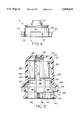
- FIG. 3 is a cross-sectional view of the mounting base, omitting the removable adapter, and which is taken substantially along lines 3--3 of FIG. 2;
- FIG. 4 is a side elevational view taken substantially along lines 4--4 of FIG. 3;
- FIG. 5 is a view similar to FIG. 1 but illustrating an alternate embodiment of the present invention.
- a filter assembly generally indicated by the numeral 10 includes a housing 12 consisting of cup-shaped portion terminating in an opened end 14 circumscribed by a radially outwardly projecting flange 16.
- a filter element generally indicated by the numeral 18 is received within the housing 12 through the open end 14 and consists of a substantially conventional circumferentially extending array of pleated paper 20, the upper and lower edges of which are sealed by closed end caps 22, 24 and an open end cap.
- a perforated metallic centertube 26 having a closed upper end (viewing FIG. 1) extends between the end caps 22, 24 and is circumscribed by the array 20 and resists radially inward collapse of the pleats.
- a spring 28 is disposed between the closed end of the end cap 22 and the dome shaped end 30 of the housing 12 and yieldably urges the filter element 18 toward the open end 16 of the housing 12.
- the filter element 18 and the housing 12 comprise a filter cartridge which is mounted on a filter base generally indicated by the numeral 32.
- An adapter 34 is secured to one end of the base 32 by bolts (not shown) received in registering apertures 36 in the base 32 and the adapter 34.
- Adapter 34 is provided with a threaded opening 38 which may be "spun-on" a threaded mounting boss (not shown) which extends from the filter mounting surface of a conventional internal combustion engine (not shown).
- a circumferentially extending gasket or O-ring seal 40 circumscribes the threaded opening 38.
- the base 32 and adapter 34 are spun onto the aforementioned mounting stud until the gasket 40 is brought into sealing engagement with the mounting surface.
- the base 32 and adapter 34 are only mounted on the engine once, and the filter cartridge may be changed periodically without removal of the base 32 from the engine.
- the mounting filter base 32 may be permanently installed on the engine when the engine is manufactured, in which case the adapter 34 is not required.
- a gasket or O-ring seal 44 is clamped between the adapter 34 and base 32 when the latter are assembled by installing bolts in the apertures 36.
- Gasket or O-ring seal 44 has appropriate openings which register with a pair of inlet openings 42 to permit communication from the inlet openings 42 through the gasket into inlet passages 46 in base 32.
- outlet passage 48 which is defined in a boss 50 carried by base 32 through the gasket 44 and into the threaded opening 38.
- the boss 50 projects axially from the upper surface 52 of base 32 and defines a circumferentially extending support surface 54, against which the filter element 18 is urged by the spring 28 when the filter cartridge is installed upon the base.
- Lubricating oil is communicated through inlet openings 42 and the inlet passages 46 across the surface 52 and into an inlet chamber 56 defined between circumferentially extending wall 58 of the housing 12 and the outer tips of the pleats comprising the array 20. Liquid is then filtered through the array 20 and is received within the outlet chamber defined within the centertube 26. Liquid then communicates through the outlet passage 48 and threaded opening 38 back into the engine.
- the base 32 defines a circumferentially extending surface 60 which is received in the open end 14 of the housing 12 and which slidably engages the circumferentially extending wall 58.
- a circumferentially extending O-ring seal 62 is carried by the circumferentially extending surface 60 and sealingly engages the circumferentially extending wall 58.
- Circumferentially spaced, radially projecting bayonet lugs 64 project outwardly from the surface 60 and are separated by recesses 66.
- a collar 68 circumscribes the housing 12 and carries radially inwardly projecting, circumferentially extending bayonet lugs 69.
- the bayonet lugs 69 cooperate with the body of the collar to define a cavity 70 therebetween having a shoulder 72 which engages the flange 16. Accordingly, when a new cartridge is to be installed on the base 32, the collar 68 is slipped over the housing 12 until the shoulder 72 is engaged with the flange 16. The bayonet lugs 69 are then introduced into the recesses 66, and the collar 68 is then rotated one quarter turn to engage the lugs 69 with the lugs 64. Axially extending portion 71 of the lugs 64 acts as a stop against which the lugs 69 engage when the collar is rotated to the fully engaged position.
- Axially extending detent 73 locks against the opposite end of the lugs 69 from the end engaging the portion 71, and acts as a safety catch to force the serviceman to move the collar 68 a small distance axially before it is rotated counterclockwise to disengage the lugs 69 from the lugs 64, again permitting the lugs 69 to be removed through the recesses 66.
- the spring 28 then urges the housing 12 away from the base 32, permitting whatever pressure exists within the housing to leak past the seal 62 before the housing is finally removed from the base.
- the housing 12 may either be permanent or discardable each time the filter is changed. If the housing 12 is permanent, the element 18 can be easily removed from the housing and disposed of and a new element installed within the housing 12 before the latter is reinstalled on the base 32.
- a relief valve within the housing that is discarded each time the filter is changed. This relief valve opens to permit flow directly from the inlet to the outlet, bypassing the filter element, to thereby prevent engine damage in the event of a clogged filter.
- a permanent relief valve generally indicated by the numeral 74 is provided in the base 32 when required.
- a bore 76 is provided in the base 32 that communicates with the inlet chamber 56 through an aperture 78 in the surface 52.
- a valve seat 80 circumscribes lower portion of the bore 76.
- a valve member 82 is urged against the valve seat 80 by a spring 84 which bears against a retainer 86 which is snapped into a recess 88 on the wall of the bore 76.
- the spring 84 is sufficiently strong that the valve member 82 normally is sealingly engaged with the valve seat 80 when the filter is used, so that the lubricating oil communicated into inlet chamber 56 communicates through the filter element 18 and out through the outlet passage 48.
- the valve element 82 opens, thereby communicating lubricating oil directly from the inlet chamber 56 into the outlet passage 48, which shares an open wall with the bore 76. Accordingly, lubricating oil bypasses the filter element 18, and passes directly from inlet chamber 56 to outlet passage 48.
- the housing 12 and collar 68 are incorporated within as a single housing member generally indicated by the numeral 190.
- the bayonet lugs 69 on the collar 68 of the preferred embodiment are incorporated as at 169 in radial outwardly extending portion 192 of the housing 190.
- the lugs 169 are engaged with the lugs 164 of the base 132 in exactly the same manner as the lugs of the collar 68 are engaged with the lugs 64 of the base 32 of the preferred embodiment.
- the housing 190 defines a circumferentially extending wall 158 which sealingly engages seal 162 carried in circumferentially extending surface 160 of the base 132.
Abstract
Description
Claims (4)
Priority Applications (1)
| Application Number | Priority Date | Filing Date | Title |
|---|---|---|---|
| US08/150,334 US5605624A (en) | 1992-01-22 | 1993-11-09 | Quick connect/disconnect liquid filter |
Applications Claiming Priority (3)
| Application Number | Priority Date | Filing Date | Title |
|---|---|---|---|
| US82393992A | 1992-01-22 | 1992-01-22 | |
| US4905493A | 1993-04-19 | 1993-04-19 | |
| US08/150,334 US5605624A (en) | 1992-01-22 | 1993-11-09 | Quick connect/disconnect liquid filter |
Related Parent Applications (1)
| Application Number | Title | Priority Date | Filing Date |
|---|---|---|---|
| US4905493A Continuation | 1992-01-22 | 1993-04-19 |
Publications (1)
| Publication Number | Publication Date |
|---|---|
| US5605624A true US5605624A (en) | 1997-02-25 |
Family
ID=25240182
Family Applications (1)
| Application Number | Title | Priority Date | Filing Date |
|---|---|---|---|
| US08/150,334 Expired - Lifetime US5605624A (en) | 1992-01-22 | 1993-11-09 | Quick connect/disconnect liquid filter |
Country Status (2)
| Country | Link |
|---|---|
| US (1) | US5605624A (en) |
| WO (1) | WO1993014858A1 (en) |
Cited By (20)
| Publication number | Priority date | Publication date | Assignee | Title |
|---|---|---|---|---|
| US20020079695A1 (en) * | 1996-07-12 | 2002-06-27 | Mykrolis Corporation | Connector apparatus and system including connector apparatus |
| US20030213736A1 (en) * | 2000-05-12 | 2003-11-20 | Hajime Hiranaga | Filters |
| US20040189002A1 (en) * | 2001-09-13 | 2004-09-30 | Niemeyer J. Karl | Separation module |
| US20060070961A1 (en) * | 2000-09-13 | 2006-04-06 | Marc Laverdiere | Liquid filtration device |
| US20060096934A1 (en) * | 2004-11-05 | 2006-05-11 | Weinberger Keith R | Oil filter assembly |
| US20060118474A1 (en) * | 2004-12-07 | 2006-06-08 | Mann & Hummel Gmbh | Liquid filter |
| US20060151371A1 (en) * | 2005-01-11 | 2006-07-13 | Weinberger Keith R | Oli filter assembly |
| US20070102924A1 (en) * | 2001-09-13 | 2007-05-10 | Niermeyer J K | Separation module |
| US20070187316A1 (en) * | 2006-02-13 | 2007-08-16 | Weinberger Keith R | Oil filter assembly |
| DE102014017250A1 (en) | 2013-11-28 | 2015-05-28 | Mann + Hummel Gmbh | Quick coupling device and filter assembly |
| USD740915S1 (en) | 2014-04-10 | 2015-10-13 | Unger Marketing International, Llc | Water purification device |
| USD742997S1 (en) | 2014-04-10 | 2015-11-10 | Unger Marketing International, Llc | Water purification media device |
| US20170274303A1 (en) * | 2016-03-23 | 2017-09-28 | Deere & Company | Quick change oil filter |
| USD849886S1 (en) | 2017-08-28 | 2019-05-28 | Unger Marketing International, Llc | Water purification device |
| US10414671B2 (en) | 2014-04-10 | 2019-09-17 | Unger Marketing International, Llc | Filter assembly with locking cover |
| USD907742S1 (en) | 2018-03-07 | 2021-01-12 | Unger Marketing International, Llc | Water purification media device |
| US11148082B2 (en) | 2015-04-10 | 2021-10-19 | Unger Marketing International, Llc | Fluid purification device |
| US11154800B2 (en) | 2015-04-10 | 2021-10-26 | Unger Marketing International, Llc | Fluid purification device |
| USD958928S1 (en) | 2018-11-01 | 2022-07-26 | Unger Marketing International, Llc | Water purification media device |
| US11911720B2 (en) | 2014-04-10 | 2024-02-27 | Unger Marketing International, Llc | Fluid purification device |
Families Citing this family (6)
| Publication number | Priority date | Publication date | Assignee | Title |
|---|---|---|---|---|
| DE69624086T2 (en) * | 1995-12-27 | 2003-05-28 | Denso Corp | Housing for exchangeable filter cartridges |
| US6136183A (en) * | 1997-04-24 | 2000-10-24 | Denso Corporation | Relief valve for filter device |
| US6006924A (en) * | 1997-05-14 | 1999-12-28 | Pti Technologies, Inc. | Multi-media filtration system with reusable and demountable filter cartridge |
| JP2007046522A (en) * | 2005-08-09 | 2007-02-22 | Honda Motor Co Ltd | Lid separation type vessel |
| US11577187B2 (en) | 2020-12-31 | 2023-02-14 | Sogefi Air & Cooling Usa, Inc. | Reinforced spin on rechargeable filter and related method of manufacture |
| US11607629B2 (en) | 2020-12-31 | 2023-03-21 | Sogefi Air & Cooling Usa, Inc. | Indexed filter element for spin on rechargeable filter and related method of use |
Citations (10)
| Publication number | Priority date | Publication date | Assignee | Title |
|---|---|---|---|---|
| US3502221A (en) * | 1968-05-14 | 1970-03-24 | Spraying Systems Co | Filter unit for sprayers |
| US3616933A (en) * | 1969-10-08 | 1971-11-02 | Baldwin Mfg Co J A | Spin-on throwaway-type oil filters |
| US4371439A (en) * | 1980-05-08 | 1983-02-01 | Fram Corporation | Cam actuated filter assembly |
| GB2130912A (en) * | 1982-11-20 | 1984-06-13 | Sartorius Gmbh | Filter housing |
| EP0210363A1 (en) * | 1985-06-29 | 1987-02-04 | Robert Bosch Gmbh | Air drier for compressed-air systems |
| EP0318079A1 (en) * | 1987-11-23 | 1989-05-31 | Fairey Arlon B.V. | Filter device and filter cartridge therefor |
| US4992166A (en) * | 1988-06-13 | 1991-02-12 | Facet Enterprises, Inc. | Plastic fluid filter and method for manufacturing same |
| US5017285A (en) * | 1989-06-28 | 1991-05-21 | Stanadyne Automotive Corp. | Fuel filter and cartridge assembly |
| US5203994A (en) * | 1991-08-16 | 1993-04-20 | Stanadyne Automotive Corp. | Fuel filter retention system |
| EP0231862B1 (en) * | 1986-01-27 | 1994-05-04 | Cuno Incorporated | Quick-change filter cartridge and head therefor |
-
1992
- 1992-12-22 WO PCT/US1992/011060 patent/WO1993014858A1/en active Application Filing
-
1993
- 1993-11-09 US US08/150,334 patent/US5605624A/en not_active Expired - Lifetime
Patent Citations (10)
| Publication number | Priority date | Publication date | Assignee | Title |
|---|---|---|---|---|
| US3502221A (en) * | 1968-05-14 | 1970-03-24 | Spraying Systems Co | Filter unit for sprayers |
| US3616933A (en) * | 1969-10-08 | 1971-11-02 | Baldwin Mfg Co J A | Spin-on throwaway-type oil filters |
| US4371439A (en) * | 1980-05-08 | 1983-02-01 | Fram Corporation | Cam actuated filter assembly |
| GB2130912A (en) * | 1982-11-20 | 1984-06-13 | Sartorius Gmbh | Filter housing |
| EP0210363A1 (en) * | 1985-06-29 | 1987-02-04 | Robert Bosch Gmbh | Air drier for compressed-air systems |
| EP0231862B1 (en) * | 1986-01-27 | 1994-05-04 | Cuno Incorporated | Quick-change filter cartridge and head therefor |
| EP0318079A1 (en) * | 1987-11-23 | 1989-05-31 | Fairey Arlon B.V. | Filter device and filter cartridge therefor |
| US4992166A (en) * | 1988-06-13 | 1991-02-12 | Facet Enterprises, Inc. | Plastic fluid filter and method for manufacturing same |
| US5017285A (en) * | 1989-06-28 | 1991-05-21 | Stanadyne Automotive Corp. | Fuel filter and cartridge assembly |
| US5203994A (en) * | 1991-08-16 | 1993-04-20 | Stanadyne Automotive Corp. | Fuel filter retention system |
Cited By (39)
| Publication number | Priority date | Publication date | Assignee | Title |
|---|---|---|---|---|
| US20040070201A1 (en) * | 1996-07-12 | 2004-04-15 | Mykrolis Corporation | Connector apparatus and system including connector apparatus |
| US20040070200A1 (en) * | 1996-07-12 | 2004-04-15 | Mykrolis Corporation | Connector apparatus and system including connector apparatus |
| US20020079695A1 (en) * | 1996-07-12 | 2002-06-27 | Mykrolis Corporation | Connector apparatus and system including connector apparatus |
| US20050126985A1 (en) * | 1996-07-12 | 2005-06-16 | Mykrolis Corporation | Connector apparatus and system including connector apparatus |
| US20050133435A1 (en) * | 1996-07-12 | 2005-06-23 | Mykrolis Corporation | Method and system for purging a dispensed fluid within a fluid dispensing system including a filter-free connector apparatus |
| US7815805B2 (en) | 1996-07-12 | 2010-10-19 | Entegris, Inc. | Connector apparatus and system including connector apparatus |
| US20030213736A1 (en) * | 2000-05-12 | 2003-11-20 | Hajime Hiranaga | Filters |
| US20070107601A1 (en) * | 2000-09-13 | 2007-05-17 | Marc Laverdiere | Liquid filtration device |
| US20060070961A1 (en) * | 2000-09-13 | 2006-04-06 | Marc Laverdiere | Liquid filtration device |
| US20080302712A1 (en) * | 2000-09-13 | 2008-12-11 | Entegris, Inc. | Liquid filtration device |
| US20040189002A1 (en) * | 2001-09-13 | 2004-09-30 | Niemeyer J. Karl | Separation module |
| US20070102924A1 (en) * | 2001-09-13 | 2007-05-10 | Niermeyer J K | Separation module |
| US20060096934A1 (en) * | 2004-11-05 | 2006-05-11 | Weinberger Keith R | Oil filter assembly |
| US7267768B2 (en) * | 2004-12-07 | 2007-09-11 | Mann & Hummel Gmbh | Liquid filter |
| US20060118474A1 (en) * | 2004-12-07 | 2006-06-08 | Mann & Hummel Gmbh | Liquid filter |
| US20060151371A1 (en) * | 2005-01-11 | 2006-07-13 | Weinberger Keith R | Oli filter assembly |
| US20070187316A1 (en) * | 2006-02-13 | 2007-08-16 | Weinberger Keith R | Oil filter assembly |
| DE102014017250A1 (en) | 2013-11-28 | 2015-05-28 | Mann + Hummel Gmbh | Quick coupling device and filter assembly |
| USD740915S1 (en) | 2014-04-10 | 2015-10-13 | Unger Marketing International, Llc | Water purification device |
| US11911720B2 (en) | 2014-04-10 | 2024-02-27 | Unger Marketing International, Llc | Fluid purification device |
| USD911486S1 (en) | 2014-04-10 | 2021-02-23 | Unger Marketing International, Llc | Water purification media device |
| USD798996S1 (en) | 2014-04-10 | 2017-10-03 | Unger Marketing International, Llc | Water purification media device |
| US11535530B2 (en) | 2014-04-10 | 2022-12-27 | Unger Marketing International, Llc | Media purification devices having intergral flow controllers |
| USD828488S1 (en) | 2014-04-10 | 2018-09-11 | Unger Marketing International, Llc | Water purification media device |
| USD742997S1 (en) | 2014-04-10 | 2015-11-10 | Unger Marketing International, Llc | Water purification media device |
| US10414671B2 (en) | 2014-04-10 | 2019-09-17 | Unger Marketing International, Llc | Filter assembly with locking cover |
| US10829396B2 (en) | 2014-04-10 | 2020-11-10 | Unger Marketing International, Llc | Media purification devices having integral flow controllers |
| US11148082B2 (en) | 2015-04-10 | 2021-10-19 | Unger Marketing International, Llc | Fluid purification device |
| US11154800B2 (en) | 2015-04-10 | 2021-10-26 | Unger Marketing International, Llc | Fluid purification device |
| US11806647B2 (en) | 2015-04-10 | 2023-11-07 | Unger Marketing International, Llc | Fluid purification device |
| CN107227988A (en) * | 2016-03-23 | 2017-10-03 | 迪尔公司 | Quick-replaceable oil filter |
| US20170274303A1 (en) * | 2016-03-23 | 2017-09-28 | Deere & Company | Quick change oil filter |
| GB2549825B (en) * | 2016-03-23 | 2022-02-23 | Deere & Co | Quick change oil filter |
| US11351488B2 (en) * | 2016-03-23 | 2022-06-07 | Deere & Company | Quick change oil filter |
| GB2602889A (en) * | 2016-03-23 | 2022-07-20 | Deere & Co | Quick change oil filter |
| GB2602889B (en) * | 2016-03-23 | 2022-10-05 | Deere & Co | Quick change oil filter |
| USD849886S1 (en) | 2017-08-28 | 2019-05-28 | Unger Marketing International, Llc | Water purification device |
| USD907742S1 (en) | 2018-03-07 | 2021-01-12 | Unger Marketing International, Llc | Water purification media device |
| USD958928S1 (en) | 2018-11-01 | 2022-07-26 | Unger Marketing International, Llc | Water purification media device |
Also Published As
| Publication number | Publication date |
|---|---|
| WO1993014858A1 (en) | 1993-08-05 |
Similar Documents
| Publication | Publication Date | Title |
|---|---|---|
| US5605624A (en) | Quick connect/disconnect liquid filter | |
| US5300223A (en) | Quick connect/disconnect oil filter | |
| US4500425A (en) | Pump valve for liquid separator | |
| US5084162A (en) | Push-on automotive filter | |
| EP0839563B1 (en) | Fluid filter with drain valve | |
| US5186829A (en) | Fuel filter key system | |
| US4144168A (en) | Fluid filter | |
| JP3072436B2 (en) | Fuel filter device | |
| US5180490A (en) | Lubricant filter assembly with internal bypass lock-out | |
| EP0489731B1 (en) | Relief valve for liquid filter | |
| US5584987A (en) | Fluid filter assemblies | |
| US4853118A (en) | Liquid filter | |
| EP0518865B1 (en) | Heavy duty air filter with multipurpose end seal | |
| US20070193929A1 (en) | Housing for environmentally friendly filter cartridge | |
| US5256280A (en) | Combination valve for liquid filter | |
| WO1991003301A1 (en) | Fuel filter | |
| US3690460A (en) | Relief valve for oil filters or the like | |
| US5037539A (en) | Liquid filter with bypass passage | |
| US4783256A (en) | Adapter assembly for filter arrangement | |
| CA2190076C (en) | Improvements in anti-drain back/pressure relieved filter cartridges | |
| EP0423192B1 (en) | Liquid filter | |
| US3259247A (en) | Filter | |
| NZ245952A (en) | Automotive oil filter; cannister fits to base using bayonet lugs | |
| CA1079699A (en) | Disposable centrifugal separator | |
| US3003637A (en) | Filters |
Legal Events
| Date | Code | Title | Description |
|---|---|---|---|
| STCF | Information on status: patent grant |
Free format text: PATENTED CASE |
|
| FEPP | Fee payment procedure |
Free format text: PAYOR NUMBER ASSIGNED (ORIGINAL EVENT CODE: ASPN); ENTITY STATUS OF PATENT OWNER: LARGE ENTITY |
|
| FPAY | Fee payment |
Year of fee payment: 4 |
|
| FPAY | Fee payment |
Year of fee payment: 8 |
|
| FPAY | Fee payment |
Year of fee payment: 12 |
|
| AS | Assignment |
Owner name: FRAM GROUP IP LLC, NEW ZEALAND Free format text: ASSIGNMENT OF ASSIGNORS INTEREST;ASSIGNOR:HONEYWELL INTERNATIONAL INC.;REEL/FRAME:026671/0907 Effective date: 20110729 |
|
| AS | Assignment |
Owner name: CREDIT SUISSE AG, AS FIRST LIEN COLLATERAL AGENT, Free format text: SECURITY AGREEMENT;ASSIGNORS:FRAM GROUP IP LLC;PRESTONE PRODUCTS CORPORATION;REEL/FRAME:026732/0670 Effective date: 20110729 |
|
| AS | Assignment |
Owner name: CREDIT SUISSE AG, AS SECOND LIEN COLLATERAL AGENT, Free format text: SECURITY AGREEMENT;ASSIGNORS:FRAM GROUP IP LLC;PRESTONE PRODUCTS CORPORATION;REEL/FRAME:026740/0089 Effective date: 20110729 |
|
| AS | Assignment |
Owner name: FRAM GROUP IP LLC, ILLINOIS Free format text: RELEASE BY SECURED PARTY;ASSIGNOR:CREDIT SUISSE AG, CAYMAN ISLANDS BRANCH, AS COLLATERAL AGENT;REEL/FRAME:041189/0938 Effective date: 20161223 Owner name: CREDIT SUISSE AG, CAYMAN ISLANDS BRANCH, AS COLLAT Free format text: SECURITY INTEREST;ASSIGNOR:FRAM GROUP IP LLC;REEL/FRAME:041190/0001 Effective date: 20161223 Owner name: FRAM GROUP IP LLC, ILLINOIS Free format text: RELEASE BY SECURED PARTY;ASSIGNOR:CREDIT SUISSE AG, CAYMAN ISLANDS BRANCH, AS COLLATERAL AGENT;REEL/FRAME:041189/0782 Effective date: 20161223 Owner name: CREDIT SUISSE AG, CAYMAN ISLANDS BRANCH, AS COLLAT Free format text: SECURITY INTEREST;ASSIGNOR:FRAM GROUP IP LLC;REEL/FRAME:041190/0278 Effective date: 20161223 |
|
| AS | Assignment |
Owner name: BMO HARRIS BANK, N.A., AS SUCCESSOR COLLATERAL AGE Free format text: ASSIGNMENT OF ASSIGNORS INTEREST;ASSIGNOR:CREDIT SUISSE AG, CAYMAN ISLANDS BRANCH, AS RESIGNING COLLATERAL AGENT;REEL/FRAME:041739/0040 Effective date: 20170216 |
|
| AS | Assignment |
Owner name: FRAM GROUP IP LLC, OHIO Free format text: RELEASE OF TERM LOAN PATENT SECURITY INTEREST;ASSIGNOR:CREDIT SUISSE AG, CAYMAN ISLANDS BRANCH, AS COLLATERAL AGENT;REEL/FRAME:048455/0869 Effective date: 20190226 Owner name: FRAM GROUP IP LLC, OHIO Free format text: RELEASE OF ABL PATENT SECURITY INTEREST;ASSIGNOR:BMO HARRIS BANK N.A., AS COLLATERAL AGENT;REEL/FRAME:048455/0808 Effective date: 20190226 |