US5614855A - Delay-locked loop - Google Patents
Delay-locked loop Download PDFInfo
- Publication number
- US5614855A US5614855A US08/512,597 US51259795A US5614855A US 5614855 A US5614855 A US 5614855A US 51259795 A US51259795 A US 51259795A US 5614855 A US5614855 A US 5614855A
- Authority
- US
- United States
- Prior art keywords
- phase
- output
- signal
- current
- charge pump
- Prior art date
- Legal status (The legal status is an assumption and is not a legal conclusion. Google has not performed a legal analysis and makes no representation as to the accuracy of the status listed.)
- Expired - Fee Related
Links
Images


Classifications
-
- H—ELECTRICITY
- H03—ELECTRONIC CIRCUITRY
- H03L—AUTOMATIC CONTROL, STARTING, SYNCHRONISATION, OR STABILISATION OF GENERATORS OF ELECTRONIC OSCILLATIONS OR PULSES
- H03L7/00—Automatic control of frequency or phase; Synchronisation
- H03L7/06—Automatic control of frequency or phase; Synchronisation using a reference signal applied to a frequency- or phase-locked loop
- H03L7/08—Details of the phase-locked loop
- H03L7/081—Details of the phase-locked loop provided with an additional controlled phase shifter
- H03L7/0812—Details of the phase-locked loop provided with an additional controlled phase shifter and where no voltage or current controlled oscillator is used
- H03L7/0816—Details of the phase-locked loop provided with an additional controlled phase shifter and where no voltage or current controlled oscillator is used the controlled phase shifter and the frequency- or phase-detection arrangement being connected to a common input
-
- H—ELECTRICITY
- H03—ELECTRONIC CIRCUITRY
- H03L—AUTOMATIC CONTROL, STARTING, SYNCHRONISATION, OR STABILISATION OF GENERATORS OF ELECTRONIC OSCILLATIONS OR PULSES
- H03L7/00—Automatic control of frequency or phase; Synchronisation
- H03L7/06—Automatic control of frequency or phase; Synchronisation using a reference signal applied to a frequency- or phase-locked loop
- H03L7/08—Details of the phase-locked loop
- H03L7/081—Details of the phase-locked loop provided with an additional controlled phase shifter
Landscapes
- Stabilization Of Oscillater, Synchronisation, Frequency Synthesizers (AREA)
- Synchronisation In Digital Transmission Systems (AREA)
- Dram (AREA)
- Pulse Circuits (AREA)
Abstract
A delay locked loop (DLL) is described in which a phase detector compares the phase of the output of the DLL with that of a reference input. The output of the phase comparator drives a differential charge pump which functions to integrate the phase comparator output signal over time. The charge pump output controls a phase shifter with unlimited range that adjusts the phase of the DLL output so that the output of the phase comparator is high 50% of the time on average. Because the DLL adjusts the phase shifter until the output of the phase detector is high 50% of the time, on average, the relationship of the DLL output clock to the input reference clock depends only on the type of phase detector used. For example, when a data receiver is used as the phase detector in the DLL, the output of the DLL is a clock signal which can be used as a sampling clock for data receivers elsewhere in the system, and is timed to sample data at the optional instant independent of temperature, supply voltage and process variations. Alternatively, a quadrature phase detector may be employed to generate a clock signal that possesses a quadrature (90° ) relationship with a reference clock signal input. This may be used, for example, to generate a transmit clock for a data transmission device. Furthermore, the DLL is controlled to minimize dither jitter while minimizing acquisition time. In addition, duty cycle correcting amplifiers are employed to produce a DLL output clock that has a desired duty cycle, for example 50%. Additionally, the inputs to the charge pump are reversed in alternate quadrants of the phase plane in order to enable unlimited phase shift with a finite control voltage range.
Description
This is a continuation of application Ser. No. 08/196,583, filed Feb. 15, 1994 now abandoned.
1. Field of the Invention
The present invention relates to a circuit to generate periodic signals such as clock signals. More particularly, the present invention relates to a delay locked loop.
2. Art Background
Many high speed electrical systems possess critical timing requirements which dictate the need to generate a periodic clock wave form that possesses a precise time relationship with respect to some reference signal. Conventionally, a phase locked loop (PLL) which employs a voltage control oscillator (VCO) is used to provide the desired clock signal. An example of a PLL is shown in FIG. 1a. However, VCO-based PLLs have some undesirable characteristics. For example, acquisition of the desired timing relationship which requires multiple iterations of signal through the PLL is often slow (typically many hundreds or thousands of clock cycles) because of the time required to drive the VCO to the correct frequency. Furthermore, designing VCOs with ample power supply rejection characteristics is difficult, particularly when implementing circuitry in CMOS, as power supply voltages utilized in such circuitry are designed to be lower and lower to conserve power. An alternative PLL circuit is the delay locked loop (DLL) which generates an output signal a predetermined delay from the input reference signal. A block diagram illustration is shown in FIG. 1b.
It is therefore an object of the present invention to provide a delay locked loop that eliminates the need for a voltage controlled oscillator (VCO) and provides both rapid acquisition and the minimization of power supply induced jitter. Another object is to provide a DLL with an unlimited phase shift range.
In the circuit of the present invention a phase detector compares the phase of the output of the delay lock loop (DLL) with that of a reference input. The output of the phase comparator is a binary signal which indicates whether the output signal of the DLL is ahead or behind the reference input signal in phase and drives a differential charge pump which functions to integrate the phase comparator output signal over time. The charge pump output controls a phase shifter that adjusts the phase of the DLL output so that the output of the phase comparator is in one state, for example, a high state, 50% of the time on average. Because the DLL adjusts the phase shifter until the output of the phase detector is in one state 50% of the time, on average, the output of the DLL is a signal that has a desired time relationship with the reference clock input, independent of temperature, supply voltage and process. For example, in one embodiment, the DLL may be used to generate a sampling clock for data receivers elsewhere in a system. In such a case, a replica data receiver would be used as the phase detector. In an alternative embodiment, a quadrature phase detector would be used to generate an output clock in quadrature with the reference clock input. This may be used to generate the timing necessary to transmit an output signal.
In one embodiment of the DLL of the present invention, the incoming clock signal is first processed through a duty cycle corrector which produces an output clock waveform that possesses a 50% duty cycle independent of the input duty cycle. The duty cycle corrected signal is then input to the phase shifter. Optionally, a second duty cycle corrector may be employed to process the output signal of the phase shifter to compensate for any duty cycle distortion caused by the phase shifter and/or subsequent buffer amplifiers. The embodiment further includes a phase shifter that has unlimited range.
In addition, the embodiment preferably includes circuitry to minimize jitter. For example, increasing the current to the charge pump in the circuit is one way to reduce acquisition time. However, as the current is increased, so is the amount of jitter generated. To reduce acquisition time without incurring excessive jitter, the DLL includes circuitry to selectively generate boosted charge pump current. The boosted charge pump current is generated only during the acquisition process, during which the signal is synchronized to the reference. When not in the acquisition process, the current is lowered from the boosted amount in order that the amount of jitter generated is decreased. A control signal is used to signal the start and end of acquisition and therefore controls the amount of current input to the charge pump. Thus, during non-acquisition phases of the process, the current is decreased, thereby minimizing jitter.
The objects, features and advantages of the present invention will be apparent to one skilled in the art from the following detailed description in which:
FIG. 1a illustrates a prior art phase locked loop.
FIG. 1b illustrates a prior art delay locked loop.
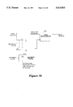
FIG. 2 illustrates one embodiment of the delay locked loop of the present invention.
FIGS. 3a and 3b illustrate embodiments of a quadrature phase detector utilized in embodiments of the delay locked loop of the present invention.
FIG. 4 illustrates one embodiment of a duty cycle correcting amplifier utilized in one embodiment of the delay locked loop of the present invention.
FIGS. 5a, 5b and 5c illustrate one embodiment of the phase shifter utilized in one embodiment of the delay locked loop of the present invention.
FIGS. 6a and 6b illustrate one embodiment of a charge pump utilized in one embodiment of the delay locked loop of the present invention.
FIGS. 7a and 7b illustrate the delay locked loop of the present invention with a compensating phase detector respectively used in data receivers and data transmitters.
FIG. 8 is a block diagram illustration of an alternate embodiment of the delay locked loop of the present invention in which the control voltage to the differential charge pump is generated by a phase detector, digital filter and digital to analog converter which controls the differential charge pump using alternate acquisition criteria.
In the following description, for purposes of explanation, numerous details are set forth in order to provide a thorough understanding of the present invention. However, it will be apparent to one skilled in the art that these specific details are not required in order to practice the present invention. In other instances, well-known electrical structures and circuits are shown in block diagram form in order not to obscure the present invention unnecessarily.
The delay locked loop (DLL) of the present invention provides for a DLL which employs a phase shifting element that provides a continuously adjusting phase shift. Furthermore, the DLL of the present invention possesses superior jitter characteristics that permits more rapid acquisition with minimum jitter.
A simplified block diagram of one embodiment of the DLL is shown in FIG. 2. The reference signal, such as a clock signal, is input to a duty cycle correcting amplifier 100 and a phase detector 110. Phase detector 110 compares the phase of the output signal of the delay locked loop with that of the reference signal input. The reference signal input represents the signal to be corrected using the DLL. Preferably, the phase detector 110 is a phase comparator wherein the output of the phase detector is a binary signal that is high if the feedback clock input, that is the output of the DLL, is ahead in phase of the reference clock input and low if the feedback clock input is behind the reference clock input. Alternately, the phase detector can be configured to generate a low output if the feedback clock input is ahead in phase of the reference clock input and generate a high output if the feedback clock input is behind the reference clock input. The output of the phase comparator drives a charge pump 120, preferably a differential charge pump, which functions to integrate the phase comparator output signals over time. The charge pump 120 output controls the phase shifter 130. The phase shifter 130 adjusts the phase of the reference signal input to the duty cycle correcting amplifier 100, so that the output of the phase comparator is high 50% of the time, on average. The DLL generates the output signal by delaying the input signal. The output signal dithers ahead and behind the desired relationship such that the phase difference detected between the reference signal and the output signal of the DLL is 50% of the time ahead and 50% of the time behind, to provide an average phase relationship which corresponds to the desired timing relationship between the output signal and the reference input signal.
However, by generating the output signal by delaying the input clock signal, the input clock signal may produce a deleterious effect on the performance of the DLL. Specifically, variations in duty cycle of the input signal from the norm, for example, a 50% duty cycle, negatively impacts the performance of the DLL. Conventional PLLs, to the contrary, are largely insensitive to the duty cycles of the incoming signal. To minimize this problem, a duty cycle correcting amplifier 100 is used. Duty cycle correcting amplifier 100 receives the input signal and produces an output signal that possesses a 50% duty cycle independent of the input signal duty cycle. The output of the duty cycle correcting amplifier 100 is input to phase shifter 130. Optionally, a second duty cycle correcting amplifier 140 may be employed to compensate for any duty cycle distortion to the signal caused by the phase shifter and/or subsequent buffer amplifiers 150. Buffer amplifiers 150 restore the signal to full rail to function as the signal output of the circuit.
The DLL of the present invention does not employ proportional control; i.e., the output of the phase detector is not proportional to the size of the phase error. Rather, the DLL is constructed such that the phase of the DLL output signal actually dithers around the desired value. As dithering is a form of jitter, it is desirable to minimize jitter to the greatest practical extent by choosing the amount of phase correction per clock cycle to be appropriately small by, for example, choosing a suitably small ratio of charge pump current to integrating capacitance. Unfortunately, by minimizing jitter, acquisition time, that is, the time required to acquire the desired relationship between the DLL output signal and the reference signal, is not minimized as the smaller the current used, the greater the acquisition time.
Therefore, to reduce acquisition time without incurring excessive dither jitter, it is preferred that the DLL includes circuitry to boost charge pump currents during acquisition. By boosting charge pump currents during acquisition, acquisition speed is increased. However, by keeping currents to a minimum while not in acquisition, the amount of jitter generated is minimized. To boost charge pump currents during acquisition, a boost control signal 160 is used to signal the start and end of the acquisition mode whereby, during acquisition mode, the charge pump currents are increased and when not in acquisition mode, charge pump currents are decreased, thereby minimizing dither jitter. Alternately, the maximization of acquisition speed may be controlled by the DLL circuit itself rather than by an external control signal as shown in FIG. 2. For example, the DLL circuit may include logic to determine if the deviation from the reference clock is greater than a predetermined value, at which time the charge pump currents should be increased to increase the speed of acquisition. When the desired timing relationship is achieved, the logic returns the charge pump circuits to their low jitter values.
As noted above, the phase detector functions to determine the phase difference between the input signal and the signal output from the DLL. In one embodiment, the phase detector utilized is a quadrature phase detector which causes the DLL to produce an output signal that is in quadrature (i.e., possesses a 90° phase shift) with the input signal. Exemplary phase detectors are illustrated in FIGS. 3a and 3b.
FIG. 3a illustrates one embodiment of a quadrature phase detector 10 which detects the quadrature phase error between two input signals that are in quadrature phase relationship and have different voltage swing characteristics. FIG. 3b illustrates an alternate embodiment of quadrature phase detector 40 which minimizes the phase detection error induced by parasitic capacitance.
Referring to FIG. 3a, Phase detector 10 includes transistors 11 through 14 and 19 through 21. For one embodiment, transistors 11-14 and 19-21 are metal oxide semiconductor field effect transistors ("MOSFETs") and are in a complementary metal oxide semiconductor ("CMOS") configuration. For other embodiments, transistors 11-14 and 19-21 can be N-channel MOSFET transistors or P-channel MOSFET transistors. For alternative embodiments, other devices, such as bipolar transistors, may be used.
As illustrated, transistors 11-14 are P-channel transistors that are connected as current sourcing transistors between a power supply voltage VDD and nodes 15 and 16. Alternatively, transistors 11-14 can be N-channel transistors or bipolar transistors.
Transistors 11-14 together constitute the load of phase detector 10. Transistors 11-14 present a high differential impedance between nodes 15-16 and a low common mode resistance from the power supply VDD to nodes 15-16. Diode connected transistors 11-12 serve as a low common mode resistance between the power supply VDD and nodes 15-16. Transistors 11-12 also constitute a positive differential load resistance between nodes 15 and 16. Transistors 13-14 constitute a negative differential load resistance between nodes 15 and 16. The negative differential load resistance cancels the positive differential load resistance. As a result, transistors 11-14 together present the high differential load resistance between nodes 15 and 16. The connection of transistors 11-14 is described below.
Alternatively, other types of load circuits can be used in phase detector 10 between the power supply VDD and nodes 15-16. In addition, the load formed by transistors 11-14 can be any other kind of high differential impedance load circuit.
The drain of transistors 11 and 14 are connected to node 15 and the drain of transistors 12 and 13 are connected to node 16. Each of transistors 11-12 has its gate coupled to its drain. In addition, the gate of transistor 13 is connected to the gate of transistor 11, and the gate of transistor 14 is connected to the gate of transistor 12. Because the gates of transistors 11 and 13 are connected together and the gates of transistors 12 and 14 are connected together, transistor 13 mirrors the current through transistor 11 and transistor 14 mirrors the current through transistor 12. In other words, transistors 11 and 13 constitute a current mirror and transistors 12 and 14 constitute another current mirror. By mirroring the current flowing through transistor 11 to node 16 and by mirroring the current flowing through transistor 12 to node 15, each of nodes 15-16 receives substantially the same amount of current and no differential current is generated. This therefore causes transistors 11-14 to present a high differential load resistance because the negative differential load resistance generated by transistors 13-14 cancels the positive differential load resistance generated by transistors 11-12. In one embodiment, transistors 11-14 are substantially identical in size such that the negative differential load resistance generated by transistors 13-14 cancels the positive differential load resistance generated by transistors 11-12.
Nodes 15-16 form the output of the phase detector 10. A capacitor 17 is connected between ground and node 15 and a capacitor 18 is connected to node 16 and ground. For one embodiment, capacitors 17 and 18 have substantially equivalent capacitance. As illustrated, capacitors 17 and 18 include parasitic capacitances of transistors 11-14 at nodes 15-16, respectively. However, capacitors 17 and 18 may also be identified not to include the parasitic capacitances of transistors 11-14 at nodes 15-16, respectively.
For purposes of the present discussion, the VIN1 signal exhibits a full CMOS voltage swing. The VIN2 signal, in a quadrature phase relationship with VIN1, is a small voltage swing signal that oscillates substantially symmetrically around the VREF reference voltage (which is a constant DC reference voltage). The VIN2 signal is therefore referred to as quasi-differential signal. Therefore, it can be seem that the VIN2 and VREF signals are not complementary to each other.
Alternatively, the VIN2 signal is a small swing, fully differential signal that swings between a Vhigh voltage and a Vlow voltage. In this case, the VREF signal is complementary to the VIN2 signal. Thus, when the gate of transistor 19 receives the Vhigh voltage, the gate of transistor 20 receives the Vlow voltage.
Transistors 19-21 detect the quadrature phase error of the VIN1 and VIN2 input signals. The VIN1 and VIN2 signals are desired to have a quadrature phase relationship. When quadrature phase error occurs (i.e., the desired quadrature phase relationship has not been achieved), phase detector 10 detects that condition by producing a net differential voltage across nodes 15-16 (i.e., the output VOUT) at the end of each measurement cycle. The voltage level of the net differential voltage across nodes 15-16 is a function of the amount of quadrature phase error between the VIN1 and VIN2 input signals. If phase detector 10 does not detect any quadrature phase error, phase detector 10 does not produce any net differential voltage across nodes 15-16 at the end of the detection cycle.
The operation of phase detector 10 is now described. Transistor 21 connects a current I from node 23 to current source 24 when the VIN1 signal is at the high VDD voltage. Because transistor 21 is connected to current source 24, transistor 21, when conducting, only allows the amount of current I to flow through. The VIN1 signal controls the start of each detection cycle. Whenever the voltage level of the VIN1 signal rises to the VDD voltage, a detection cycle is initiated.
When the voltage level of the VIN2 signal is higher than that of the VREF voltage and when the VIN1 signal is at the VDD voltage (e.g., from time t1 to time t2), transistor 19 conducts more than transistor 20 does. Transistor 19 thus contributes substantially all the I current to node 23. Because each of nodes 15 and 16 receives substantially the same amount of current from the load element formed by transistors 11-14, capacitor 17 is charged differently than capacitor 18 if transistors 19 and 20 are not drawing the same amount of current to node 23. In this case, capacitor 18 may be charging while capacitor 17 is discharging. This in turn generates a differential voltage across nodes 15-16, and therefore at the output VOUT of phase detector 10. The differential voltage at the output VOUT ramps linearly upwards for the time that the voltage of the VIN2 signal is higher than the VREF reference voltage.
When the voltage level of the VIN2 signal is lower than that of the VREF voltage and when the VIN1 signal is at the VDD voltage (e.g., from time t2 to time t3), transistor 20 then contributes substantially all the I current to node 23. This in turn causes the charging of capacitors 17-18 to be uneven. In this case, capacitor 17 may be charging while capacitor 18 is discharging. This then results in the differential voltage at the output VOUT of phase detector 10 to drop linearly downwards.
When the voltage level of the VIN1 signal goes to ground, the differential voltage at the output VOUT stops changing. If the VIN1 and VIN2 signals are in perfect quadrature, the differential voltage across nodes 15-16 ramps linearly towards zero and no net differential voltage will be developed at the VOUT output of phase detector 10 at the time when the VIN1 signal goes to ground. If, however, a quadrature phase error exists between the VIN1 and VIN2 signals, a net differential voltage will be developed across nodes 15-16 at the end of the phase detection cycle. The net differential voltage across nodes 15-16 is substantially proportional to the amount of the quadrature phase error.
Preferably the output VOUT of phase detector 10 is connected to a comparator 39 to generate a binary quadrature phase error output. Other circuits may also be used to generate the binary quadrature phase error output.
The above description of phase detector 10 in detecting the quadrature phase error, however, assumes the desirable situation in which the influence of any parasitic capacitance 25 of transistors 19 through 21 at node 23 (as well as other parasitic capacitances in the circuit) is negligible. Since transistor 21 is used as a switch, parasitic capacitor 25 includes the parasitic capacitance between the source of transistor 21 and ground.
Due to the existence of parasitic capacitor 25 in the circuit of phase detector 10, phase detector 10 generates a net differential voltage at the output VOUT of the circuit at the end of a detection cycle even when the VIN1 and VIN2 signals are in the perfect quadrature phase relationship.
The embodiment illustrated by FIG. 3b eliminates the net differential voltage occurring at the output of the circuit due to the parasitic capacitance. Referring to FIG. 3b, phase detector 40 includes transistors 41 through 44 connected between the power supply VDD and nodes 45 and 46. The connection and function of transistors 41-44 in phase detector 40 are identical to that of transistors 11-14 in phase detector 10 of FIG. 3a.
For one embodiment, transistors 49-51 and 52-54 are N-channel MOSFET transistors. For alternative embodiments, transistors 49-51 and 52-54 can be P-channel MOSFET transistors or bipolar transistors. For one embodiment, the size of each of transistors 52-53 is substantially equal to that of each of transistors 49-50 and the size of transistor 54 is substantially equal to that of transistor 51.
A parasitic capacitor 57 is connected to node 55 and ground and a parasitic capacitor 58 connected to node 56 and ground. Parasitic capacitor 57 includes the parasitic capacitance of transistors 49-51 at node 55 and parasitic capacitor 58 includes the parasitic capacitance of transistors 52-54 at node 56. Parasitic capacitor 57 also includes other parasitic capacitances in the circuit. Since transistor 51 is used as a switch, parasitic capacitor 57 includes the parasitic capacitance between the source of transistor 51 and ground. Likewise, parasitic capacitor 58 also includes other parasitic capacitances in the circuit. Because transistor 54 is used as a switch, parasitic capacitor 58 includes the parasitic capacitance between the source of transistor 54 and ground.
Transistors 49-51 detect the phase error of the VIN1 and VIN2 signals. Transistors 52-54 cancel the net differential voltage at the output VOUT of phase detector 40 due to parasitic capacitor 57 in the circuit. As described above, each of transistors 52-53 has a size that is substantially equal to that of each of transistors 49-50. Therefore, the capacitance of parasitic capacitor 58 is substantially equal to that of parasitic capacitor 57. Due to the negative cancellation effect of transistors 52-54, the additional error currents generated in the circuit due to parasitic capacitors 57-58 cancel each other and the phase detector 40 does not experience a net differential voltage generated at the output VOUT of the circuit due to the parasitic capacitance of the circuit. Because the capacitance of parasitic capacitors 57-58 is substantially equal, the additional error currents associated with parasitic capacitors 57-58 are also substantially equal. Transistors 49-50 and 52-53 are, however, cross-connected such that their respective contributions subtract from each other. This causes the additional error currents to cancel each other and allows phase detector 40 to detect the quadrature phase error of the VIN1 and VIN2 signals with minimized phase detection error.
The operation will now be discussed. When transistor 51 is turned on by the logical high VIN1 signal, the voltage level at node 55 does not change immediately, causing the current flowing through transistor 51 to exceed the current I1, which generates an additional error current. Since the voltage level of the VIN2 signal is higher than the VREF voltage at this time, this additional error current flows through transistor 49, causing capacitor 47 to be additionally discharged. Meanwhile, since transistor 54 is also turned on by the logical high VIN1 signal, the voltage level at node 56 does not change immediately, which also generates an additional error current flowing through transistor 54. As the voltage level of the VIN2 signal is higher than the VREF voltage at this time, an additional error current flows through transistor 52, causing capacitor 48 to be additionally discharged. Because the capacitance of parasitic capacitor 57 is equal to that of parasitic capacitor 58, the additional error current that flows through transistor 52 is substantially equal to the additional error current through transistor 49. Given that transistor 52 is connected to node 46 while transistor 49 is connected to node 45, the additional error current generated by transistor 52 cancels that generated by transistor 49.
When the voltage level of the VIN2 signal is lower than that of the VREF voltage, transistor 49 is much less conducting than transistor 50 and transistor 52 is much less conducting than transistor 53. At this time, the voltage level at each of nodes 55 and 56 falls. This causes parasitic capacitors 57 and 58 to be discharged, reducing the current flowing through transistors 50 and 53, respectively. This then causes an additional error current to flow through transistor 50 to capacitor 48 and an additional current to flow through transistor 53 to capacitor 47, additionally charging capacitors 47 and 48, respectively. Given that transistor 50 is connected to node 46 and transistor 53 is connected to node 45 and given that the additional error currents through transistors 50 and 53 are substantially equal to each other, the additional charging to each of capacitors 47 and 48 cancels each other.
In addition, due to parasitic capacitors 57 and 58, the voltage level at each of nodes 55 and 56 does not change immediately after transistors 51 and 54 are turned off by the VIN1 signal, causing an additional error current to flow through transistor 50 to parasitic capacitor 51 and an additional error current to flow through transistor 53 to parasitic capacitor 58. The additional error currents cause capacitors 47 and 48 to be additional discharged, respectively. Because the capacitance of parasitic capacitor 57 is substantially equal to that of parasitic capacitor 58, the additional error current flowing through transistor 50 is substantially equal to the additional error current flowing through transistor 53. Given that transistor 50 is connected to node 46 and transistor 53 is connected to node 45, the additional error currents cancel each other. By doing so, no net differential voltage due to parasitic capacitor 58 will be developed at the output VOUT and phase detector 40 detects the quadrature phase error of the VIN1 and VIN2 signals with minimized detection error. The VOUT output of phase detector 40 is connected to a comparator 39 to generate a binary quadrature phase error output. Alternatively, other circuits can be used to generate the binary quadrature phase error output.
The duty cycle correcting amplifier circuit receives periodic input signals that possess an imperfect duty cycle, and outputs periodic output signals with a corrected duty cycle through the use of active duty cycle correction. In one embodiment, the circuit receives the uncorrected periodic input signal and generates an intermediate signal current reflective of the uncorrected input signal. The intermediate signal current is summed with a correction current which offsets the signal current. The summed current is input to an integrating capacitance. The voltage across the integrating capacitance is clamped to a finite value. The capacitance and clamping voltage are chosen so that the voltage across the capacitor ramps substantially linearly (i.e., slew limits) over a substantial fraction of the period of the input signal. The slew-limited, clamped capacitor voltage signal then drives an amplifier that regenerates a substantially square wave form as output. By varying the amount of the correction current, an uncorrected input signal having a non-linear ramp input (e.g., the rising edge and falling edge of the signal being substantially unequal) can be modified to have a linear input and the duty cycle of the regenerated wave form can be varied over a range constrained mainly by the fraction of the period that is dominated by the slewing process.
One embodiment of the duty cycle correcting amplifier is shown in FIG. 4. The amplifier receives as input the uncorrected input signal IN1+110 and IN1-115 and the error values, error+125, error-120. The error signals are generated by the duty cycle error measurement circuit which measures the duty cycle error. The output of the circuit is the corrected differential clock signal 150, 155. The circuit consists of two operational transconductance amplifiers (OTAs) connected in parallel. The uncorrected clock signal input 110, 115, drives transistor pair M3, M4. The gain of transistors M3 and M4 are made sufficiently high so that substantially all of the bias current I1BIAS 130 flows alternately through transistors M3 and M4, depending upon the polarity of the input signal. The duty cycle error signal 120, 125, generated by the duty cycle error measurement circuit, drives transistor pair M1 and M2. The output current generated is then added to the current generated by transistors M3 and M4. Inverters Inv1 and Inv2 160, 165 are preferably ideal infinite gain inverters such that the output of the inverter changes state when a predetermined threshold value is crossed thus helping in the formation of the square wave output.
The output of the OTAs are the common drain connection of transistors M8 and M10, node 170, and the common drain connection of transistors M5 and M9, node 175. Preferably the bias currents I1BIAS, I2BIAS, 130, 140 are chosen in combination with the capacitance associated with the common drain connection and clamping voltage (in the present embodiment, the clamping voltage is substantially equal to the power supply voltage VDD ) to provide the desired slew limiting characteristics to correct the duty cycle of the input signal. Alternately, a separate capacitance component may be utilized to provide the integrating capacitance functionality. Furthermore, other considerations, such as noise and/or jitter performance, may dictate the greater operating current or explicit additional capacitance connected to the OTA outputs 170, 175. Therefore, an explicit additional capacitance would then be connected to the OTA outputs 170, 175 to provide the necessary slew limiting characteristics. For example, a capacitor may be connected between nodes 170, 175, the drain nodes of transistors M9 and M10. Alternately, separate capacitor components may be connected between node 170 and ground and node 175 and ground.
FIG. 5a illustrates the phase shifter of one embodiment of the present invention. The phase shifter uses phase mixing to provide an unlimited phase adjustment range. Phase mixing includes the mixing of two intermediate signals of different phase that are derived from the input signal. In the present embodiment, the intermediate signals are four quadrature intermediate signals that have relative phase alignments of zero, 90, 180 and 270 degrees. The output signal always has a phase that falls within a quadrant of the phase plane that is bounded by two of the four intermediate signals. Phase mixing is accomplished by multiplying each intermediate signal that bounds the quadrant in which the phase of the output signal is located by a weighting fraction and summing the results.
The phase shifter 560 includes a delay circuit 570 (with input 565), a phase interpolator 580 and a phase selector 562. The delay circuit 570 outputs four intermediate signals via signal line 575 that are used in the phase mixing process by the phase interpolator 580. In the present embodiment, the delay circuit preferably outputs intermediate signals having relative phase alignments of 0, 90, 180 and 270 degrees. Any fixed delay that results from the delay circuit 570 and the phase interpolator 580 is eliminated from the output signal by virtue of the phase shifter 560 being a component in a feedback loop.
One method for providing quadrature intermediate signals requires that the delay circuit to also perform a frequency divide operation on the input signal such that the frequency of the intermediate signals are one-half that of the input frequency. If this method is implemented, the phase shifter circuit of FIG. 5a can be modified, as shown in FIG. 5c, to include an XOR gate 640 and a second phase interpolator 620 having an output signal that is 90 degrees out of phase with the output of the phase interpolator 610. The outputs of both phase interpolators 610, 620 are the inputs to the XOR gate 640, the XOR gate 640 functioning to double the frequency such that the output frequency of the phase shifter is equal to the input frequency. The circuit of FIG. 5c includes delay circuit 605 having an input 601.
FIG. 5b illustrates one simplified embodiment of the phase interpolator. The phase interpolator includes a differential pair of n-channel field effect transistors (FETs) 502 and 503. The differential control voltages VC+ and VC- are coupled to the gates of FETs 502 and 503 respectively. In conjunction with fixed current sources 504 and 505, the differential pair 502 and 503 steers a differential current into branches 506 and 507 under the control of VC+ and VC-. The currents provided by 504 and 505 are each less than the current provided by current source 501 in the illustrative embodiments to ensure that a finite difference (VC+ - VC-) can result in a zero current in either branch 506 or branch 507.
The value of the differential control voltage VC determines the amount of current that is steered through the right and left halves of the phase interpolator. The current in branch 506 is equal to the difference of the current supplied by current source 504 and the drain current of FET 502. Similarly, the current in branch 507 is equal to the difference of the current supplied by current source 505 and the drain current of 503. When VC is equal to VMAX, FET 502 is switched completely on by the VC+ differential control voltage such that FET 502 conducts substantially all of the current from current source 501. The negative differential control voltage VC- is negative such that FET 503 is not conducting. This means that current flows through branch 507, and no current flows through branch 506. When VC is equal to VMIN, substantially all of the current provided by current source 501 flows through FET 503. Thus, current flows through branch 506, and no current flows through branch 507. Control voltage levels VC between VMAX and VMIN allow current to flow through both branches 506 and 507.
The current in the right and left halves of the phase interpolator are used to charge the capacitors 590 and 595, which are coupled to the positive and negative terminals of comparator 596, respectively. The comparator 596 preferably acts as an ideal comparator, as is well-known in the art. Phase mixer 550 determines which two of the four intermediate phase vectors are to be used to couple and decouple the capacitors 590 and 595 from branches 506 and 507 in response to the select signals received via signal line 525. The intermediate signals are received via signal line 515.
As VC varies, the currents flowing in the capacitors 590 and 595 vary from depending entirely on the first bounding intermediate vector to depending entirely on the second bounding intermediate vector. The relative amount of current that is flowing into each capacitor, as set by the differential control voltage VC, determines the relative rate of charging and discharging of the capacitors. The comparator 596 outputs a logic high when it detects that the voltage at the positive terminal becomes more positive than voltage at the negative terminal. Because the voltages of capacitors 590 and 595 are time varying wave forms, the output of the comparator indicates when the wave forms of the two capacitors intersect. This point of intersection is varied by varying the differential control voltage VC.
Although any type of a charge pump may be used to supply current to the phase shifter, it is preferred that a differential charge pump be used. One embodiment of a differential charge pump is illustrated in FIG. 6a. In the embodiment shown in FIG. 6a, the load is formed of a quad of P-channel MOS devices. The transistors M3 and M6 are diode-connected, and are located in parallel with cross-connected transistors M4 and M5. For use in a charge pump circuit, transistors M3, M4, M5 and M6 are all made to be substantially of the same size. An integration capacitance C1 is shown as a single device connected to the drains of the drive transistors M1 and M2.
The signals driving the gates of drive transistors M1 and M2 are assumed to be large enough in amplitude to switch substantially all of the current 2I of the current source into the integrating capacitance C1.
The diode-connected devices, M3, M6, together present a positive differential resistance. The positive differential resistance by itself provides an undesirable leakage path for the integrating capacitance. To mitigate this leakage, the current through M3, M6 is canceled by the function of transistors M4, M5, which function can be viewed as that of a negative resistance. Thus, transistors M4, M5 cancel out the leakage of M3, M6 in the following manner.
Transistors M3 and M4 comprise a current mirror. Assuming ideal behavior, the two devices carry the same current. Because the drains of devices M3 and M4 are connected to opposite sides of the capacitance, the net contribution by this connection to the differential current is zero. By symmetry, the same reasoning applies to the current mirror formed by transistors M5, M6, so that the net differential resistance presented by transistors M3, M4, M5, M6 is ideally infinite, leaving only finite differential output resistance of the driving pair M1, M2, and the inherent capacitor leakage as differential loss mechanisms.
In practice, however, mismatches in the transistors cause departures from ideal behavior. Hence, it is desirable to choose the effective resistance of the diode-connected devices M3, M6 as high as possible such that any imperfect cancellation by respectively M4, M5, will have a proportionally smaller effect. The effect of finite differential output resistance of M1, M2, is usually negligible, because there is an inherent cascoding effect by M1, M2 on the current source. The charge pump switches all the current 2I into the integrating capacitance by the control input signals in either a positive or negative direction. For example, if M1 is turned on and M2 is turned off, transistor M1 acts as a cascoding device for the current source (which source is assumed to be realized with a transistor or collection of transistors), boosting the effective impedance.
This argument applies symmetrically to the case where M2 is on and M1 is off. Hence, the leakage caused by M1, M2 is generally negligible. Further advantage of the invention is that the common-mode output voltage of the charge pump is simply lower than the positive supply voltage by one source-to-gate voltage of a P-channel device.
Therefore, if the charge pump is ever disabled, for example, by shutting off the current source, recovery is relatively quick because common-mode levels cannot be moved far from their equilibrium active values.
FIG. 6b shows a second embodiment of the charge pump circuit of the present invention. For this embodiment, an alternate connection of the integrating capacitance is employed. For some circuits, the most area-efficient capacitance is formed from the gate structure of a MOS transistor. Such capacitors require DC bias that is in excess of approximately one threshold voltage to maximize capacitance and to avoid excessive non-linearities. In this embodiment, the biasing criterion is satisfied by splitting the capacitor into two equal capacitors and coupling each capacitor to Vss. By connecting each capacitor to Vss, this embodiment provides filtering of power supply (Vdd) noise. Any noise on the positive power supply that couples through the p-channel load devices is bypassed by the capacitors, reducing greatly the amount of the noise passed on to any subsequent stage.
To provide unlimited phase shift using a charge pump with a finite control voltage range, the charge pump is preceded with a multiplexer 123 or similar means, as is well known in the art, to reverse the direction of the charge pump in alternate quadrants. The control signal to operate the multiplexer 123 is provided by the phase shifter 130. For example, when the DLL is out of lock, the phase detector 110 will output a constant signal, either a high or a low. In this instance, the charge pump could integrate up until it reaches its maximum voltage value. The phase shifter 130 would then sense this condition, switch quadrants in the phase shifter 130, and switch the multiplexer that precedes the charge pump to select a complimentary input. The charge pump would then reverse directions and integrate down until either phase lock is achieved or another quadrant boundary is reached. This enables the charge pump to continue to output a control voltage to provide infinite phase shift range, even though the charge pump itself has a finite output range.
An alternate embodiment of the delay locked loop of the present invention is shown in FIG. 7a. In this embodiment, the DLL 310, for example the DLL circuit of FIG. 2, may be used to compensate for the set-up time of the data receiver 320 located in a remote section of a high speed digital system in which input data signal transitions are centered between the incoming clock signal edges. In the present illustration, a data receiver substantially similar to the data receiver 320 functions as the phase detector in the DLL 310. Because DLL 310 adjusts the signal using the phase shifter until the output of the phase detector is high 50% of the time, on average, by definition this condition corresponds to a sample clock signal that is timed to sample the incoming data at the optimal instants, independent of temperature, supply voltage and process variations. For example, if the setup time of data receiver 320 is 1 nanosecond, the sample clock signal will be delayed 1 nanosecond from the input clock signal. If the setup time value of 1 nanosecond varies with process, temperature and supply voltage variations, the DLL 310 automatically compensates as the data receiver/phase detector of the DLL 310 will likewise vary with process, temperature and supply voltage variations.
Another embodiment is shown in FIG. 7b. DLL 312 is utilized to generate the clock signals to transmit data in a digital system. More particularly, DLL 312 enables data signal output transitions to be precisely centered between the incoming clock signal edges. In this embodiment, a transmit clock signal, the phase of which is in quadrature with the incoming clock signal edges, is generated. Preferably the quadrature phase detector of FIG. 3 is used as the phase detector element in DLL 312. The transmit clock signal is input to the data transmitter 322 to control the timing of data output from the system.
Referring to FIG. 8, in an alternate embodiment, the output of the phase detector may be input to a digital filter or other signal processing device, such as a processor or state machine, which examines the sequence of phase comparator outputs and enables boosted currents for acquisition when appropriate. For example, if the phase of the DLL output clock has been behind that of the input clock for a predetermined number of cycles, boosted acquisition is enabled. Therefore, for example, in a most general case, a binary search may be performed on a plurality of comparator outputs to determine a corresponding boosted current value to utilize.
The invention has been described in conjunction with the preferred embodiment. It is evident that numerous alternatives, modifications, variations and uses will be apparent to those skilled in the art in light of the foregoing description.
Claims (3)
1. A circuit for generating an output signal in a predetermined timing relationship with an input signal, comprising:
a duty cycle correcting amplifier coupled to receive the input signal, said amplifier correcting the duty cycle of the input signal to a predetermined duty cycle to produce a duty cycle corrected input signal;
a phase detector coupled to receive the input signal and the output signal, said phase detector generating an output signal indicative of whether the output signal is ahead or behind the input signal in phase;
a charge pump coupled to receive the output of the phase detector, said charge pump generating an output current; and
a phase shifter coupled to receive the duty cycle corrected input signal, the output signal from the phase detector and the output current from the charge pump, said phase shifter performing a phase shift of the duty cycle corrected input signal to produce the output signal, said phase shifter driven by the output current of the charge pump, said direction of the phase shift indicated by the phase detector;
wherein the phase of the output signal dithers around the phase of the input signal such that the output of the phase detector is a signal of a first state 50% of the time, on average.
2. A circuit for generating an output signal in a predetermined timing relationship with an input signal, comprising:
a phase detector coupled to receive the input signal and the output signal, said phase detector generating an output signal indicative of whether the output signal is ahead or behind the input signal in phase;
a charge pump coupled to receive the output of the phase detector, said charge pump generating an output current;
a boost control signal coupled to the charge pump, said signal indicating when the circuit is in an acquisition mode wherein the circuit functions to acquire the desired timing relationship between the input signal and the output signal, said charge pump generating greater output current when said boost control signal is in a first state indicative that the circuit is in the acquisition mode;
a phase shifter coupled to receive the input signal, the output signal from the phase detector and the output current from the charge pump, said phase shifter performing a phase shift of the input signal to produce the output signal, said phase shifter driven by the output current of the charge pump, said direction of the phase shift indicated by the phase detector;
wherein the jitter in the circuit is minimized by increasing the current output by the charge pump when the circuit is in the acquisition mode and maintaining the current output at a lower level when the circuit is not in the acquisition mode.
3. A method for generating an output signal having a predetermined timing relationship with an input signal, said method comprising the steps of:
correcting the duty cycle of the input signal to a predetermined duty cycle to produce a duty cycle corrected input signal;
generating a phase output signal indicative of whether the output signal is ahead or behind the input signal in phase;
generating a current; and
performing a phase shift of the duty cycle corrected input signal to produce the output signal, said step driven by the current, said direction of the phase shift indicated by the phase detector;
wherein the phase of the output signal dithers around the phase of the input signal such that the output of the phase detector is a signal of a first state 50% of the time, on average.
Priority Applications (1)
| Application Number | Priority Date | Filing Date | Title |
|---|---|---|---|
| US08/512,597 US5614855A (en) | 1994-02-15 | 1995-08-21 | Delay-locked loop |
Applications Claiming Priority (2)
| Application Number | Priority Date | Filing Date | Title |
|---|---|---|---|
| US19658394A | 1994-02-15 | 1994-02-15 | |
| US08/512,597 US5614855A (en) | 1994-02-15 | 1995-08-21 | Delay-locked loop |
Related Parent Applications (1)
| Application Number | Title | Priority Date | Filing Date |
|---|---|---|---|
| US19658394A Continuation | 1994-02-15 | 1994-02-15 |
Publications (1)
| Publication Number | Publication Date |
|---|---|
| US5614855A true US5614855A (en) | 1997-03-25 |
Family
ID=22725972
Family Applications (1)
| Application Number | Title | Priority Date | Filing Date |
|---|---|---|---|
| US08/512,597 Expired - Fee Related US5614855A (en) | 1994-02-15 | 1995-08-21 | Delay-locked loop |
Country Status (5)
| Country | Link |
|---|---|
| US (1) | US5614855A (en) |
| JP (2) | JP3754070B2 (en) |
| KR (1) | KR100393317B1 (en) |
| AU (1) | AU1841895A (en) |
| WO (1) | WO1995022206A1 (en) |
Cited By (212)
| Publication number | Priority date | Publication date | Assignee | Title |
|---|---|---|---|---|
| US5764091A (en) * | 1995-01-25 | 1998-06-09 | Matsushita Electric Industrial Co., Ltd. | Method and system for clock-signal waveform correction |
| US5781056A (en) * | 1995-09-27 | 1998-07-14 | Ando Electric Co., Ltd. | Variable delay circuit |
| WO1998037656A2 (en) * | 1997-02-06 | 1998-08-27 | Rambus, Inc. | Delay locked loop circuitry for clock delay adjustment |
| US5825209A (en) * | 1997-02-27 | 1998-10-20 | Rambus Inc. | Quadrature phase detector |
| US5907253A (en) * | 1997-11-24 | 1999-05-25 | National Semiconductor Corporation | Fractional-N phase-lock loop with delay line loop having self-calibrating fractional delay element |
| US5920518A (en) * | 1997-02-11 | 1999-07-06 | Micron Technology, Inc. | Synchronous clock generator including delay-locked loop |
| US5926047A (en) * | 1997-08-29 | 1999-07-20 | Micron Technology, Inc. | Synchronous clock generator including a delay-locked loop signal loss detector |
| US5940609A (en) * | 1997-08-29 | 1999-08-17 | Micorn Technology, Inc. | Synchronous clock generator including a false lock detector |
| US5940608A (en) * | 1997-02-11 | 1999-08-17 | Micron Technology, Inc. | Method and apparatus for generating an internal clock signal that is synchronized to an external clock signal |
| US5943382A (en) * | 1996-08-21 | 1999-08-24 | Neomagic Corp. | Dual-loop spread-spectrum clock generator with master PLL and slave voltage-modulation-locked loop |
| US5946244A (en) * | 1997-03-05 | 1999-08-31 | Micron Technology, Inc. | Delay-locked loop with binary-coupled capacitor |
| US5953284A (en) * | 1997-07-09 | 1999-09-14 | Micron Technology, Inc. | Method and apparatus for adaptively adjusting the timing of a clock signal used to latch digital signals, and memory device using same |
| US5999027A (en) * | 1995-06-13 | 1999-12-07 | Fujitsu Limited | Phase compensating apparatus and delay controlling circuit |
| US6011732A (en) * | 1997-08-20 | 2000-01-04 | Micron Technology, Inc. | Synchronous clock generator including a compound delay-locked loop |
| US6014042A (en) * | 1998-02-19 | 2000-01-11 | Rambus Incorporated | Phase detector using switched capacitors |
| US6016282A (en) * | 1998-05-28 | 2000-01-18 | Micron Technology, Inc. | Clock vernier adjustment |
| US6029250A (en) * | 1998-09-09 | 2000-02-22 | Micron Technology, Inc. | Method and apparatus for adaptively adjusting the timing offset between a clock signal and digital signals transmitted coincident with that clock signal, and memory device and system using same |
| US6031402A (en) * | 1997-05-06 | 2000-02-29 | Lg Semicon Co., Ltd. | Clock synchronizing circuit with power save mode |
| US6047346A (en) * | 1998-02-02 | 2000-04-04 | Rambus Inc. | System for adjusting slew rate on an output of a drive circuit by enabling a plurality of pre-drivers and a plurality of output drivers |
| US6069506A (en) * | 1998-05-20 | 2000-05-30 | Micron Technology, Inc. | Method and apparatus for improving the performance of digital delay locked loop circuits |
| US6078200A (en) * | 1997-07-31 | 2000-06-20 | Nec Corporation | Clock signal generator |
| US6084452A (en) * | 1998-06-30 | 2000-07-04 | Sun Microsystems, Inc | Clock duty cycle control technique |
| US6094727A (en) * | 1998-06-23 | 2000-07-25 | Micron Technology, Inc. | Method and apparatus for controlling the data rate of a clocking circuit |
| US6101197A (en) * | 1997-09-18 | 2000-08-08 | Micron Technology, Inc. | Method and apparatus for adjusting the timing of signals over fine and coarse ranges |
| US6100736A (en) * | 1997-06-05 | 2000-08-08 | Cirrus Logic, Inc | Frequency doubler using digital delay lock loop |
| US6115318A (en) * | 1996-12-03 | 2000-09-05 | Micron Technology, Inc. | Clock vernier adjustment |
| US6133773A (en) * | 1997-10-10 | 2000-10-17 | Rambus Inc | Variable delay element |
| US6173432B1 (en) | 1997-06-20 | 2001-01-09 | Micron Technology, Inc. | Method and apparatus for generating a sequence of clock signals |
| US6181178B1 (en) | 1998-07-21 | 2001-01-30 | Samsung Electronics Co., Ltd. | Systems and methods for correcting duty cycle deviations in clock and data signals |
| US6191613B1 (en) | 1999-07-29 | 2001-02-20 | Xilinx, Inc. | Programmable logic device with delay-locked loop |
| US6194929B1 (en) * | 1997-06-25 | 2001-02-27 | Sun Microsystems, Inc. | Delay locking using multiple control signals |
| US6225831B1 (en) | 1998-12-18 | 2001-05-01 | Cypress Semiconductor Corp. | Phase detector |
| US6269451B1 (en) | 1998-02-27 | 2001-07-31 | Micron Technology, Inc. | Method and apparatus for adjusting data timing by delaying clock signal |
| US6279090B1 (en) | 1998-09-03 | 2001-08-21 | Micron Technology, Inc. | Method and apparatus for resynchronizing a plurality of clock signals used in latching respective digital signals applied to a packetized memory device |
| US6285725B1 (en) | 1997-11-21 | 2001-09-04 | Hyundai Electronics Industries Co., Ltd. | Charge pump circuit |
| US6316979B1 (en) | 1998-03-20 | 2001-11-13 | Micron Technology, Inc. | Integrated circuit data latch driver circuit |
| US6320438B1 (en) | 2000-08-17 | 2001-11-20 | Pericom Semiconductor Corp. | Duty-cycle correction driver with dual-filter feedback loop |
| US6323706B1 (en) | 2000-02-24 | 2001-11-27 | Rambus Inc. | Apparatus and method for edge based duty cycle conversion |
| US6336032B1 (en) * | 1997-12-23 | 2002-01-01 | Telefonaktiebolaget Lm Ericsson (Publ) | Method and device for phase regulation |
| US6338127B1 (en) | 1998-08-28 | 2002-01-08 | Micron Technology, Inc. | Method and apparatus for resynchronizing a plurality of clock signals used to latch respective digital signals, and memory device using same |
| US6342801B1 (en) * | 1999-06-29 | 2002-01-29 | Hyundai Electronics Industries Co., Ltd. | Duty cycle correction circuit of delay locked loop |
| US20020012152A1 (en) * | 2000-07-21 | 2002-01-31 | Broadcom Corporation | Methods and systems for digitally processing optical data signals |
| US20020017403A1 (en) * | 2000-06-09 | 2002-02-14 | Olivier Phely | Track drive device for all terrain vehicle |
| US6349399B1 (en) | 1998-09-03 | 2002-02-19 | Micron Technology, Inc. | Method and apparatus for generating expect data from a captured bit pattern, and memory device using same |
| US20020034222A1 (en) * | 2000-04-28 | 2002-03-21 | Aaron Buchwald | Methods and systems for adaptive receiver equalization |
| US6373293B1 (en) | 2000-10-02 | 2002-04-16 | Rambus Inc. | Self-synchronized, multi-sample, quadrature phase detector |
| US6374360B1 (en) | 1998-12-11 | 2002-04-16 | Micron Technology, Inc. | Method and apparatus for bit-to-bit timing correction of a high speed memory bus |
| US6373309B1 (en) * | 1999-12-16 | 2002-04-16 | Hyundai Electronics Industries Co., Ltd. | Duty cycle compensation circuit of delay locked loop for Rambus DRAM |
| US6381722B1 (en) | 1999-06-08 | 2002-04-30 | Intel Corporation | Method and apparatus for testing high speed input paths |
| US6384637B1 (en) | 2000-06-06 | 2002-05-07 | Rambus | Differential amplifier with selectable hysteresis and buffered filter |
| US6384652B1 (en) | 2000-08-17 | 2002-05-07 | Vanguard International Semiconductor Corporation | Clock duty cycle correction circuit |
| US6388485B2 (en) | 2000-03-16 | 2002-05-14 | Samsung Electronics, Co., Ltd. | Delay-locked loop circuit having master-slave structure |
| US20020073350A1 (en) * | 2000-11-30 | 2002-06-13 | Martin Ehlert | Method and configuration for generating a clock pulse in a data processing system having a number of data channels |
| US20020080898A1 (en) * | 2000-07-21 | 2002-06-27 | Broadcom Incorporated | Methods and systems for DSP-based receivers |
| US6415008B1 (en) * | 1998-12-15 | 2002-07-02 | BéCHADE ROLAND ALBERT | Digital signal multiplier |
| US20020087911A1 (en) * | 2000-12-29 | 2002-07-04 | Liu Jonathan H. | Source synchronous bus |
| US20020084857A1 (en) * | 2000-10-23 | 2002-07-04 | Samsung Electronics Co., Ltd. | Delay locked loop for improving high frequency characteristics and yield |
| US6421801B1 (en) | 1999-06-08 | 2002-07-16 | Intel Corporation | Testing IO timing in a delay locked system using separate transmit and receive loops |
| US20020101947A1 (en) * | 2001-01-31 | 2002-08-01 | Nobuya Sumiyoshi | Sampling clock generator circuit and data receiver using the same |
| US6430696B1 (en) | 1998-11-30 | 2002-08-06 | Micron Technology, Inc. | Method and apparatus for high speed data capture utilizing bit-to-bit timing correction, and memory device using same |
| US6441664B2 (en) * | 1999-12-10 | 2002-08-27 | Fujitsu Limited | Signal phase adjustment circuit to set optimum phase |
| US20020126785A1 (en) * | 1999-12-31 | 2002-09-12 | Santo Maggio | Method for recovering a clock signal in a telecommunications system and circuit thereof |
| US6452432B2 (en) | 2000-03-31 | 2002-09-17 | Samsung Electronics Co., Ltd. | Signal processing circuits having a pair of delay locked loop (DLL) circuits for adjusting a duty-cycle of a periodic digital signal and methods of operating same |
| US6466071B2 (en) | 2000-04-10 | 2002-10-15 | Samsung Electronics Co., Ltd. | Methods and circuits for correcting a duty-cycle of a signal |
| DE10132232C1 (en) * | 2001-06-29 | 2002-11-21 | Infineon Technologies Ag | Phase detector circuit for phase-regulating loop uses Exclusive-OR gates connected in circuit with integrators providing integrating loop filter |
| US20020194518A1 (en) * | 2001-06-06 | 2002-12-19 | Chang Kun-Yung Ken | Apparatus and method for generating a skip signal |
| US20030001647A1 (en) * | 2001-06-29 | 2003-01-02 | Karl Schroedinger | Method and apparatus for producing a clock output signal |
| US6513103B1 (en) | 1997-10-10 | 2003-01-28 | Rambus Inc. | Method and apparatus for adjusting the performance of a synchronous memory system |
| US6525581B1 (en) | 2001-09-20 | 2003-02-25 | Hynix Semiconductor Inc. | Duty correction circuit and a method of correcting a duty |
| US6556492B2 (en) * | 2000-07-18 | 2003-04-29 | Infineon Technologies Ag | System for testing fast synchronous semiconductor circuits |
| KR100384781B1 (en) * | 2000-12-29 | 2003-05-22 | 주식회사 하이닉스반도체 | Duty cycle correction circuit |
| US6570412B2 (en) * | 1998-08-06 | 2003-05-27 | Fujitsu Limited | Filter characteristic regulating apparatus and regulating method therefor |
| US6580304B1 (en) | 2002-03-28 | 2003-06-17 | M/A-Com, Inc. | Apparatus and method for introducing signal delay |
| US20030117864A1 (en) * | 2001-10-22 | 2003-06-26 | Hampel Craig E. | Phase adjustment apparatus and method for a memory device signaling system |
| WO2003063369A2 (en) * | 2002-01-18 | 2003-07-31 | Xilinx, Inc. | A serial to parallel and parallel to serial data transceiver |
| US20030154418A1 (en) * | 2002-02-11 | 2003-08-14 | Vandensande Geert Maria Marcel | Multiplex bus system with duty cycle correction |
| US6608530B1 (en) | 2001-12-14 | 2003-08-19 | Cypress Semiconductor Corp. | Enhanced ZDB feedback methodology utilizing binary weighted techniques |
| US6621312B2 (en) * | 2000-11-13 | 2003-09-16 | Primarion, Inc. | High bandwidth multi-phase clock selector with continuous phase output |
| US6625242B1 (en) | 1999-01-27 | 2003-09-23 | Samsung Electronics Co., Ltd. | Delay locked loops and methods that shift the phase of a delayed clock signal based on a reference phase value |
| US20030179027A1 (en) * | 2002-03-22 | 2003-09-25 | Kizer Jade M. | Locked loop with dual rail regulation |
| US20030183842A1 (en) * | 2002-03-22 | 2003-10-02 | Kizer Jade M. | System with phase jumping locked loop circuit |
| US6642746B2 (en) * | 1996-01-02 | 2003-11-04 | Rambus Inc. | Phase detector with minimized phase detection error |
| US6642760B1 (en) | 2002-03-29 | 2003-11-04 | Rambus, Inc. | Apparatus and method for a digital delay locked loop |
| US6650594B1 (en) | 2002-07-12 | 2003-11-18 | Samsung Electronics Co., Ltd. | Device and method for selecting power down exit |
| US6654900B1 (en) * | 2000-04-19 | 2003-11-25 | Sigmatel, Inc. | Method and apparatus for producing multiple clock signals having controlled duty cycles by controlling clock multiplier delay elements |
| US20040008566A1 (en) * | 2002-07-10 | 2004-01-15 | Song Ho-Young | Latency control circuit and method of latency control |
| US20040041604A1 (en) * | 2002-09-03 | 2004-03-04 | Kizer Jade M. | Phase jumping locked loop circuit |
| US20040066873A1 (en) * | 2002-10-05 | 2004-04-08 | Cho Geun-Hee | Delay locked loop circuit for internally correcting duty cycle and duty cycle correction method thereof |
| US20040076192A1 (en) * | 1999-10-19 | 2004-04-22 | Rambus Inc. | Calibrated data communication system and method |
| KR20040034985A (en) * | 2002-10-18 | 2004-04-29 | 엘지전자 주식회사 | Circuit for generating clock signal |
| US20040081013A1 (en) * | 2002-07-10 | 2004-04-29 | Samsung Electronics Co., Ltd. | Latency control circuit and method of latency control |
| US20040095174A1 (en) * | 2002-10-30 | 2004-05-20 | Sang-Hoon Hong | Duty cycle correction circuit and delay locked loop having the same |
| US20040103226A1 (en) * | 2001-06-28 | 2004-05-27 | Brian Johnson | Method and system for adjusting the timing offset between a clock signal and respective digital signals transmitted along with clock signal, and memory device and computer system using same |
| US20040130962A1 (en) * | 1994-10-06 | 2004-07-08 | Mosaid Technologies Incorporated | Delayed locked loop implementation in a synchronous dynamic random access memory |
| US20040135604A1 (en) * | 2003-01-10 | 2004-07-15 | Jong-Soo Lee | Delay locked loops having blocking circuits therein that enhance phase jitter immunity and methods of operating same |
| US20040145963A1 (en) * | 2003-01-17 | 2004-07-29 | Byon Gyung-Su | Semiconductor device including duty cycle correction circuit |
| EP1453203A1 (en) * | 2003-02-28 | 2004-09-01 | Sun Microsystems, Inc. | Miller effect compensation for a DLL phase interpolator |
| US6809600B2 (en) | 2001-09-17 | 2004-10-26 | Rambus Inc. | Dual loop phase lock loops using dual voltage supply regulators |
| US20040217788A1 (en) * | 2003-05-03 | 2004-11-04 | Kim Kyung-Hoon | Digital delay locked loop and control method thereof |
| US20040217792A1 (en) * | 2001-03-29 | 2004-11-04 | Fletcher Thomas D | Smart buffer circuit to match a delay over a range of loads |
| US20040222832A1 (en) * | 2003-05-09 | 2004-11-11 | Chaiyuth Chansungsan | Interpolator circuit |
| US6839393B1 (en) | 1999-07-14 | 2005-01-04 | Rambus Inc. | Apparatus and method for controlling a master/slave system via master device synchronization |
| US20050028019A1 (en) * | 2003-07-29 | 2005-02-03 | Kim Kyung-Hoon | Delay locked loop with improved jitter and clock delay compensating method thereof |
| US6856558B1 (en) | 2002-09-20 | 2005-02-15 | Integrated Device Technology, Inc. | Integrated circuit devices having high precision digital delay lines therein |
| US6867627B1 (en) | 2003-09-16 | 2005-03-15 | Integrated Device Technology, Inc. | Delay-locked loop (DLL) integrated circuits having high bandwidth and reliable locking characteristics |
| US20050057291A1 (en) * | 2003-09-11 | 2005-03-17 | Huy Nguyen | Configuring and selecting a duty cycle for an output driver |
| US20050083721A1 (en) * | 2001-09-07 | 2005-04-21 | Hampel Craig E. | Granularity memory column access |
| US20050091464A1 (en) * | 2003-10-27 | 2005-04-28 | Ralph James | System and method for using a learning sequence to establish communications on a high-speed nonsynchronous interface in the absence of clock forwarding |
| US6889304B2 (en) | 2001-02-28 | 2005-05-03 | Rambus Inc. | Memory device supporting a dynamically configurable core organization |
| US20050093597A1 (en) * | 2003-10-29 | 2005-05-05 | Jong-Tae Kwak | Delay locked loop and its control method |
| US20050093600A1 (en) * | 2003-10-30 | 2005-05-05 | Jong-Tae Kwak | Delay locked loop and clock generation method thereof |
| US20050099880A1 (en) * | 2001-03-15 | 2005-05-12 | Johnson James B. | Duty cycle distortion compensation for the data output of a memory device |
| US20050105365A1 (en) * | 2003-11-13 | 2005-05-19 | Hynix Semiconductor Inc. | Repair fuse box of semiconductor device |
| US6897699B1 (en) | 2002-07-19 | 2005-05-24 | Rambus Inc. | Clock distribution network with process, supply-voltage, and temperature compensation |
| US20050110540A1 (en) * | 2003-11-20 | 2005-05-26 | Jong-Tae Kwak | Delay locked loop and its control method |
| US20050110541A1 (en) * | 2003-11-20 | 2005-05-26 | Hynix Semiconductor Inc. | Delay locked loop |
| KR100499305B1 (en) * | 2002-10-18 | 2005-07-04 | 엘지전자 주식회사 | Circuit for correcting duty factor of clock signal using a couple of delay loops |
| US20050151592A1 (en) * | 2004-01-09 | 2005-07-14 | Aaron Partridge | Frequency and/or phase compensated microelectromechanical oscillator |
| US6922091B2 (en) | 2002-09-03 | 2005-07-26 | Rambus Inc. | Locked loop circuit with clock hold function |
| US6928128B1 (en) | 1999-05-03 | 2005-08-09 | Rambus Inc. | Clock alignment circuit having a self regulating voltage supply |
| US6940328B2 (en) | 2002-08-28 | 2005-09-06 | Micron Technology, Inc. | Methods and apparatus for duty cycle control |
| US6943608B2 (en) * | 2003-12-01 | 2005-09-13 | International Business Machines Corporation | Wide frequency range voltage-controlled oscillators (VCO) |
| US6952123B2 (en) | 2002-03-22 | 2005-10-04 | Rambus Inc. | System with dual rail regulated locked loop |
| US20050220235A1 (en) * | 2000-02-07 | 2005-10-06 | Stark Donald C | System and method for aligning internal transmit and receive clocks |
| US20050238128A1 (en) * | 2004-04-27 | 2005-10-27 | Hynix Semiconductor Inc. | Duty cycle correction apparatus and method for use in a semiconductor memory device |
| US20050265504A1 (en) * | 2004-05-27 | 2005-12-01 | Xyratex Technology Limited | Clock recovery circuit and a method of generating a recovered clock signal |
| US6977539B1 (en) | 2003-08-26 | 2005-12-20 | Integrated Device Technology, Inc. | Clock signal generators having programmable full-period clock skew control and methods of generating clock signals having programmable skews |
| US6981185B1 (en) * | 2002-08-09 | 2005-12-27 | Adaptec, Inc. | Methods and apparatus to correct duty cycle |
| US20050286505A1 (en) * | 1999-03-01 | 2005-12-29 | Harrison Ronnie M | Method and apparatus for generating a phase dependent control signal |
| KR100540176B1 (en) * | 2000-01-24 | 2006-01-10 | 브이케이 주식회사 | High speed and low voltage charge pump of phase locked loop |
| US20060038601A1 (en) * | 2003-08-26 | 2006-02-23 | Shawn Giguere | Clock signal generators having programmable full-period clock skew control |
| US20060039227A1 (en) * | 2004-08-17 | 2006-02-23 | Lawrence Lai | Memory device having staggered memory operations |
| KR100553833B1 (en) * | 2003-12-24 | 2006-02-24 | 삼성전자주식회사 | Circuits and Method for Controlling Inversion of Delay Locked Loop, Delay Locked Loop and Synchronous Semiconductor Memory Apparatus |
| US20060062340A1 (en) * | 2004-09-20 | 2006-03-23 | Intersil Americas, Inc. | Phase adjuster |
| US20060067146A1 (en) * | 2004-09-30 | 2006-03-30 | Steven Woo | Integrated circuit memory system having dynamic memory bank count and page size |
| US20060072366A1 (en) * | 2004-09-30 | 2006-04-06 | Ware Frederick A | Multi-column addressing mode memory system including an integrated circuit memory device |
| US20060077751A1 (en) * | 2002-07-10 | 2006-04-13 | Reum Oh | Latency control circuit and method of latency control |
| US7038520B2 (en) * | 2003-01-29 | 2006-05-02 | Fujitsu Limited | Timing signal generating circuit and receiver circuit designed to speed up signal transmission |
| US7046093B1 (en) | 2003-08-27 | 2006-05-16 | Intergrated Device Technology, Inc. | Dynamic phase-locked loop circuits and methods of operation thereof |
| US7046058B1 (en) | 2003-09-24 | 2006-05-16 | Integrated Device Technology, Ltd. | Delayed-locked loop with fine and coarse control using cascaded phase interpolator and variable delay circuit |
| US20060104151A1 (en) * | 1999-10-19 | 2006-05-18 | Rambus Inc. | Single-clock, strobeless signaling system |
| US20060109146A1 (en) * | 2002-07-09 | 2006-05-25 | Eiichi Takahashi | Digital circuit having a delay circuit for adjustment of clock signal timing |
| US20060133124A1 (en) * | 1999-12-23 | 2006-06-22 | Nader Gamini | Semiconductor package with a controlled impedance bus and method of forming same |
| US20060152265A1 (en) * | 2005-01-10 | 2006-07-13 | Joonho Kim | Duty cycle corrector |
| US20060170474A1 (en) * | 2005-02-01 | 2006-08-03 | Kim Jung P | Duty cycle corrector |
| US20060170471A1 (en) * | 2005-02-03 | 2006-08-03 | Mosaid Technologies, Inc. | Method and apparatus for initializing a delay locked loop |
| US20060197565A1 (en) * | 2005-03-02 | 2006-09-07 | Hynix Semiconductor Inc. | Delay locked loop for controlling duty rate of clock |
| US7109760B1 (en) | 2004-01-05 | 2006-09-19 | Integrated Device Technology, Inc. | Delay-locked loop (DLL) integrated circuits that support efficient phase locking of clock signals having non-unity duty cycles |
| US20060248305A1 (en) * | 2005-04-13 | 2006-11-02 | Wayne Fang | Memory device having width-dependent output latency |
| US20060261866A1 (en) * | 1999-04-30 | 2006-11-23 | Demone Paul W | Frequency-doubling delay locked loop |
| US20060279342A1 (en) * | 2005-06-14 | 2006-12-14 | Micron Technology, Inc. | DLL measure initialization circuit for high frequency operation |
| US7170323B1 (en) * | 2005-05-09 | 2007-01-30 | Pixelworks, Inc. | Delay locked loop harmonic detector and associated method |
| US20070047375A1 (en) * | 2005-08-31 | 2007-03-01 | Alessandro Minzoni | Duty cycle detector with first and second oscillating signals |
| US20070046329A1 (en) * | 2005-08-25 | 2007-03-01 | Alessandro Minzoni | Differential duty cycle restoration |
| US20070046345A1 (en) * | 2005-08-24 | 2007-03-01 | Micrel, Incorporated | In-loop duty corrector delay-locked loop for multiphase clock generation |
| EP1150427A3 (en) * | 2000-04-27 | 2007-03-21 | NEC Electronics Corporation | Clock control circuit and method |
| US7196562B1 (en) | 2003-08-26 | 2007-03-27 | Integrated Device Technology, Inc. | Programmable clock drivers that support CRC error checking of configuration data during program restore operations |
| US20070076124A1 (en) * | 2005-09-30 | 2007-04-05 | Sanyo Electric Co., Ltd. | Delay Circuit and Video Signal Processing Circuit Using the Same |
| US20070086267A1 (en) * | 2005-10-14 | 2007-04-19 | Micron Technology, Inc. | Clock generator having a delay locked loop and duty cycle correction circuit in a parallel configuration |
| US20070176659A1 (en) * | 2006-01-27 | 2007-08-02 | Micron Technology, Inc | Duty cycle error calculation circuit for a clock generator having a delay locked loop and duty cycle correction circuit |
| US20070194821A1 (en) * | 2006-02-22 | 2007-08-23 | Micron Technology, Inc. | Continuous high-frequency event filter |
| US7279938B1 (en) | 2004-01-05 | 2007-10-09 | Integrated Device Technology, Inc. | Delay chain integrated circuits having binary-weighted delay chain units with built-in phase comparators therein |
| US20070241798A1 (en) * | 2006-04-12 | 2007-10-18 | Masenas Charles J | Delay locked loop having charge pump gain independent of operating frequency |
| US20070260841A1 (en) * | 2006-05-02 | 2007-11-08 | Hampel Craig E | Memory module with reduced access granularity |
| US7323918B1 (en) | 2006-08-08 | 2008-01-29 | Micrel, Incorporated | Mutual-interpolating delay-locked loop for high-frequency multiphase clock generation |
| KR100809692B1 (en) * | 2006-08-01 | 2008-03-06 | 삼성전자주식회사 | Delay locked loop circuit having low jitter and jitter reducing method thereof |
| US20080137428A1 (en) * | 2006-11-16 | 2008-06-12 | Kabushiki Kaisha Toshiba | Power supply circuit and semiconductor memory |
| US20080165884A1 (en) * | 2007-01-04 | 2008-07-10 | Montage Technology Group, Ltd | Systems and Methods for the Distribution of Clock Signals |
| US20080174350A1 (en) * | 2007-01-24 | 2008-07-24 | Hynix Semiconductor Inc. | DLL circuit and method of controlling the same |
| US20080225560A1 (en) * | 2007-03-12 | 2008-09-18 | System General Corp. | Switching controller for parallel power converters |
| US20080292022A1 (en) * | 2007-05-21 | 2008-11-27 | Gregory Blum | Radio Receiver Including a Delay-Locked Loop (DLL) for Phase Adjustment |
| US20080301533A1 (en) * | 2003-06-12 | 2008-12-04 | Micron Technology, Inc. | Dynamic synchronization of data capture on an optical or other high speed communications link |
| US20090024367A1 (en) * | 2007-07-17 | 2009-01-22 | Caterpillar Inc. | Probabilistic modeling system for product design |
| US7500075B1 (en) | 2001-04-17 | 2009-03-03 | Rambus Inc. | Mechanism for enabling full data bus utilization without increasing data granularity |
| US20100083027A1 (en) * | 2008-09-30 | 2010-04-01 | Mosaid Technologies Incorporated | Serial-connected memory system with output delay adjustment |
| US20100079180A1 (en) * | 2008-10-01 | 2010-04-01 | Jin-Gook Kim | Ac-coupling phase interpolator and delay-locked loop using the same |
| US20100083028A1 (en) * | 2008-09-30 | 2010-04-01 | Mosaid Technologies Incorporated | Serial-connected memory system with duty cycle correction |
| US20100097112A1 (en) * | 2008-10-22 | 2010-04-22 | Harmendra Panditd | Duty cycle correction circuits having short locking times that are relatively insensitive to temperature changes |
| US20100109722A1 (en) * | 2003-06-25 | 2010-05-06 | Mosaid Technologies Incorporated | Intialization circuit for delay locked loop |
| US7728675B1 (en) | 2006-03-31 | 2010-06-01 | Cypress Semiconductor Corporation | Fast lock circuit for a phase lock loop |
| US20100156485A1 (en) * | 2008-12-23 | 2010-06-24 | Paolo Madoglio | Delay element array for time-to-digital converters |
| CN101145779B (en) * | 2006-09-12 | 2010-07-07 | 盛群半导体股份有限公司 | Phase angle generator |
| US7831769B1 (en) * | 2004-11-02 | 2010-11-09 | Symantec Operating Corporation | System and method for performing online backup and restore of volume configuration information |
| US20100321076A1 (en) * | 2009-06-17 | 2010-12-23 | Samsung Electronics Co., Ltd. | Delay-locked loop for correcting duty ratio of input clock signal and output clock signal and electronic device including the same |
| US7920665B1 (en) | 2005-09-28 | 2011-04-05 | Cypress Semiconductor Corporation | Symmetrical range controller circuit and method |
| US20110102039A1 (en) * | 2009-10-30 | 2011-05-05 | Seok-Bo Shin | Apparatus and method for correcting duty cycle of clock signal |
| US20110248752A1 (en) * | 2010-04-09 | 2011-10-13 | Micron Technology, Inc. | Clock signal generators having a reduced power feedback clock path and methods for generating clocks |
| US8120403B2 (en) | 2008-05-21 | 2012-02-21 | Elpida Memory, Inc. | Duty detection circuit |
| US20120087452A1 (en) * | 2009-06-30 | 2012-04-12 | Rambus Inc. | Techniques for Adjusting Clock Signals to Compensate for Noise |
| US8169241B2 (en) | 2008-01-15 | 2012-05-01 | Atmel Rousset S.A.S. | Proportional phase comparator and method for phase-aligning digital signals |
| CN102771077A (en) * | 2010-02-17 | 2012-11-07 | 模式转换系统有限公司 | Digital clock regenerator |
| US20120280729A1 (en) * | 2009-12-17 | 2012-11-08 | August Nathaniel J | Adaptive digital phase locked loop |
| US8390351B2 (en) | 2010-09-30 | 2013-03-05 | SK Hynix Inc. | Delay locked loop circuit of semiconductor memory apparatus |
| US8487680B1 (en) * | 2012-01-20 | 2013-07-16 | National Chung Cheng University | Full-digital clock correction circuit and method thereof |
| US8493116B2 (en) | 2010-09-15 | 2013-07-23 | Samsung Electronics Co., Ltd. | Clock delay circuit and delay locked loop including the same |
| US8595459B2 (en) | 2004-11-29 | 2013-11-26 | Rambus Inc. | Micro-threaded memory |
| US20130328602A1 (en) * | 2012-06-07 | 2013-12-12 | Fujitsu Limited | Duty ratio correction circuit, double-edged device, and method of correcting duty ratio |
| US8729941B2 (en) | 2010-10-06 | 2014-05-20 | Micron Technology, Inc. | Differential amplifiers, clock generator circuits, delay lines and methods |
| US8742807B1 (en) * | 2012-05-24 | 2014-06-03 | Ambarella, Inc. | Low supply voltage analog phase interpolator |
| US8750320B2 (en) | 1997-01-23 | 2014-06-10 | Broadcom Corporation | Fibre channel arbitrated loop bufferless switch circuitry to increase bandwidth without significant increase in cost |
| US8798091B2 (en) | 1998-11-19 | 2014-08-05 | Broadcom Corporation | Fibre channel arbitrated loop bufferless switch circuitry to increase bandwidth without significant increase in cost |
| US9018990B2 (en) * | 2012-10-30 | 2015-04-28 | Realtek Semiconductor Corp. | Duty cycle tuning circuit and method thereof |
| US9106230B1 (en) * | 2013-03-14 | 2015-08-11 | Altera Corporation | Input-output circuitry for integrated circuits |
| US9268719B2 (en) | 2011-08-05 | 2016-02-23 | Rambus Inc. | Memory signal buffers and modules supporting variable access granularity |
| US9369263B1 (en) | 2015-06-30 | 2016-06-14 | International Business Machines Corporation | Calibration of sampling phase and aperature errors in multi-phase sampling systems |
| US9453906B2 (en) | 2014-07-31 | 2016-09-27 | North Carolina State University | Phase calibration circuit and method for multi-channel radar receiver |
| CN106452393A (en) * | 2015-08-11 | 2017-02-22 | 纽艾吉科技有限公司 | Digital adaptive jitter eliminating device and method |
| CN105061729B (en) * | 2015-08-18 | 2017-07-11 | 天津大学 | The aqueous hyperbranched polymer curing agents of ambient temperature curable aqueous epoxy resins |
| US10425086B1 (en) * | 2018-04-13 | 2019-09-24 | KaiKuTek Inc. | Divider-less phase locked loop |
| US10425091B2 (en) * | 2017-10-31 | 2019-09-24 | Texas Instruments Incorporated | Fractional clock generator |
| CN113644900A (en) * | 2020-05-11 | 2021-11-12 | 原相科技股份有限公司 | Interpolation circuit and motor drive circuit |
| CN117526932A (en) * | 2024-01-08 | 2024-02-06 | 芯耀辉科技有限公司 | Clock signal generation method and device |
Families Citing this family (25)
| Publication number | Priority date | Publication date | Assignee | Title |
|---|---|---|---|---|
| JP3695833B2 (en) * | 1996-04-05 | 2005-09-14 | 株式会社ルネサステクノロジ | PLL circuit |
| US6369626B1 (en) | 1997-03-21 | 2002-04-09 | Rambus Inc. | Low pass filter for a delay locked loop circuit |
| KR100511892B1 (en) * | 1997-12-31 | 2005-11-25 | 매그나칩 반도체 유한회사 | DL Device |
| JP3678570B2 (en) * | 1998-01-17 | 2005-08-03 | 日本電気株式会社 | Semiconductor integrated circuit |
| US6111445A (en) | 1998-01-30 | 2000-08-29 | Rambus Inc. | Phase interpolator with noise immunity |
| CA2233527C (en) | 1998-03-30 | 2002-01-22 | Mitel Semiconductor Ab | Pulse amplifier with low-duty cycle errors |
| DE69914652T2 (en) * | 1998-03-27 | 2004-10-07 | Zarlink Semiconductor Ab Jaerf | Differential pulse amplifier with constant duty cycle |
| US6553529B1 (en) * | 1999-07-23 | 2003-04-22 | Teradyne, Inc. | Low cost timing system for highly accurate multi-modal semiconductor testing |
| JP4392678B2 (en) | 2000-04-18 | 2010-01-06 | エルピーダメモリ株式会社 | DLL circuit |
| JP4454810B2 (en) | 2000-08-04 | 2010-04-21 | Necエレクトロニクス株式会社 | Digital phase control method and digital phase control circuit |
| US6573779B2 (en) * | 2001-05-25 | 2003-06-03 | Rambus Inc. | Duty cycle integrator with tracking common mode feedback control |
| KR100546368B1 (en) * | 2003-08-22 | 2006-01-26 | 삼성전자주식회사 | Memory device for itself compensating clock skew occurring centering error and clock skew compensating method |
| JP3968450B2 (en) * | 2005-09-30 | 2007-08-29 | ザインエレクトロニクス株式会社 | Stereo modulator and FM stereo modulator using the same |
| KR100776903B1 (en) | 2006-04-24 | 2007-11-19 | 주식회사 하이닉스반도체 | Delay locked loop |
| KR100805698B1 (en) | 2006-08-31 | 2008-02-21 | 주식회사 하이닉스반도체 | Semiconductor memory device |
| KR100837814B1 (en) | 2006-12-22 | 2008-06-13 | 주식회사 하이닉스반도체 | Circuit for outputting data of semiconductor memory apparatus |
| KR100868016B1 (en) | 2007-04-13 | 2008-11-11 | 주식회사 하이닉스반도체 | Data Output Circuit of Semiconductor Memory Apparatus |
| KR100911190B1 (en) | 2007-06-11 | 2009-08-06 | 주식회사 하이닉스반도체 | Internal Clock Driver Circuit |
| KR100910785B1 (en) | 2007-09-27 | 2009-08-04 | 인하대학교 산학협력단 | The correction circuit of duty cycle based on dll |
| KR101003142B1 (en) | 2009-05-11 | 2010-12-22 | 주식회사 하이닉스반도체 | Clock Signal Generating Circuit and a Semiconductor Memory Apparatus including the same |
| KR101046245B1 (en) | 2009-11-30 | 2011-07-04 | 주식회사 하이닉스반도체 | Duty compensation circuit |
| KR101040245B1 (en) | 2010-02-24 | 2011-06-09 | 주식회사 하이닉스반도체 | Semiconductor apparatus |
| JP2011193334A (en) | 2010-03-16 | 2011-09-29 | Elpida Memory Inc | Internal-clock adjusting circuit |
| JP6445286B2 (en) * | 2014-09-08 | 2018-12-26 | 旭化成エレクトロニクス株式会社 | Phase detector, phase adjustment circuit, receiver and transmitter |
| EP3648348B1 (en) * | 2018-10-29 | 2022-09-28 | NXP USA, Inc. | Duty cycle monitor circuit and method for duty cycle monitoring |
Citations (114)
| Publication number | Priority date | Publication date | Assignee | Title |
|---|---|---|---|---|
| US3296517A (en) * | 1963-03-15 | 1967-01-03 | Claude C Routh | Passive broadband frequency multiplier |
| US3546604A (en) * | 1964-06-09 | 1970-12-08 | Marathon Oil Co | Phase shifters |
| US3555458A (en) * | 1966-11-24 | 1971-01-12 | Csf | Side band generator |
| US3617855A (en) * | 1970-04-24 | 1971-11-02 | Nippon Oceanics Inst Ltd | Phase-detecting circuits |
| US3675139A (en) * | 1970-01-14 | 1972-07-04 | Plessey Handel Investment Ag | Electrical demodulation systems |
| US3771063A (en) * | 1972-03-13 | 1973-11-06 | Calnor El Paso Inc | Bi-polar phase detector |
| US3825768A (en) * | 1973-02-15 | 1974-07-23 | Eaton Corp | Phase sequence and power loss detector |
| US3863080A (en) * | 1973-10-18 | 1975-01-28 | Rca Corp | Current output frequency and phase comparator |
| US3911368A (en) * | 1974-06-20 | 1975-10-07 | Tarczy Hornoch Zoltan | Phase interpolating apparatus and method |
| US3965433A (en) * | 1975-03-27 | 1976-06-22 | Bell Telephone Laboratories, Incorporated | Phase equalizer useable in a LIND amplifier |
| US3982190A (en) * | 1975-07-31 | 1976-09-21 | Rockwell International Corporation | Phaselock circuitry with lock indication |
| US3997772A (en) * | 1975-09-05 | 1976-12-14 | Bell Telephone Laboratories, Incorporated | Digital phase shifter |
| US4021742A (en) * | 1974-10-07 | 1977-05-03 | Sony Corporation | Phase compressor for phase modulated signal |
| US4110641A (en) * | 1977-06-27 | 1978-08-29 | Honeywell Inc. | CMOS voltage comparator with internal hysteresis |
| US4151463A (en) * | 1978-02-02 | 1979-04-24 | Bell Telephone Laboratories, Incorporated | Phase locked loop indicator |
| US4156851A (en) * | 1977-10-25 | 1979-05-29 | Winters Paul N | Constant-phase delay network |
| US4178554A (en) * | 1976-10-25 | 1979-12-11 | Hitachi, Ltd. | Phase difference detector |
| US4249095A (en) * | 1979-02-26 | 1981-02-03 | Rca Corporation | Comparator, sense amplifier |
| US4283682A (en) * | 1979-04-06 | 1981-08-11 | Ricoh Company, Ltd. | Erasure zone decision feedback phase lock loop for carrier recovery in data modems |
| US4285006A (en) * | 1977-07-22 | 1981-08-18 | Mitsubishi Denki Kabushiki Kaisha | Ghost cancellation circuit system |
| US4291274A (en) * | 1978-11-22 | 1981-09-22 | Tokyo Shibaura Denki Kabushiki Kaisha | Phase detector circuit using logic gates |
| US4364082A (en) * | 1980-03-12 | 1982-12-14 | Hitachi, Ltd. | Phase detection circuit and automatic tint control circuit of color television receiver utilizing the same |
| US4373204A (en) * | 1981-02-02 | 1983-02-08 | Bell Telephone Laboratories, Incorporated | Phase locked loop timing recovery circuit |
| US4383216A (en) * | 1981-01-29 | 1983-05-10 | International Business Machines Corporation | AC Measurement means for use with power control means for eliminating circuit to circuit delay differences |
| US4394587A (en) * | 1981-05-27 | 1983-07-19 | Motorola, Inc. | CMOS Differential comparator with hysteresis |
| US4468689A (en) * | 1981-10-08 | 1984-08-28 | Tokyo Shibaura Denki Kabushiki Kaisha | Color separation circuit |
| US4473762A (en) * | 1980-10-22 | 1984-09-25 | Tokyo Shibaura Denki Kabushiki Kaisha | Semiconductor integrated circuit with a response time compensated with respect to temperature |
| US4494021A (en) * | 1982-08-30 | 1985-01-15 | Xerox Corporation | Self-calibrated clock and timing signal generator for MOS/VLSI circuitry |
| US4506175A (en) * | 1982-08-18 | 1985-03-19 | Rca Corporation | Digital phase comparator circuit producing sign and magnitude outputs |
| US4520321A (en) * | 1981-11-30 | 1985-05-28 | Anritsu Electric Company Limited | Phase difference detector with phase inversion of one input signal when phase difference is small |
| US4547685A (en) * | 1983-10-21 | 1985-10-15 | Advanced Micro Devices, Inc. | Sense amplifier circuit for semiconductor memories |
| US4573022A (en) * | 1983-12-17 | 1986-02-25 | Kabushiki Kaisha Toshiba | Semiconductor integrated circuit using vertical PNP transistors |
| US4607229A (en) * | 1983-12-21 | 1986-08-19 | Kabushiki Kaisha Toshiba | Phase shifter |
| GB2140993B (en) | 1983-05-25 | 1986-11-12 | Sony Corp | Phase comparing circuit |
| US4623805A (en) * | 1984-08-29 | 1986-11-18 | Burroughs Corporation | Automatic signal delay adjustment apparatus |
| US4635097A (en) * | 1984-02-14 | 1987-01-06 | Sony Corporation | Method and system for processing digital video signal incorporating phase-correction feature |
| US4638190A (en) * | 1985-05-20 | 1987-01-20 | General Electric Company | Digitally controlled wideband phase shifter |
| US4641048A (en) * | 1984-08-24 | 1987-02-03 | Tektronix, Inc. | Digital integrated circuit propagation delay time controller |
| US4644196A (en) * | 1985-01-28 | 1987-02-17 | Motorola, Inc. | Tri-state differential amplifier |
| US4691124A (en) * | 1986-05-16 | 1987-09-01 | Motorola, Inc. | Self-compensating, maximum speed integrated circuit |
| US4719365A (en) * | 1983-12-29 | 1988-01-12 | Takeda Riken Kogyo Kabushikikaisha | Clocked logic delay device which corrects for the phase difference between a clock signal and an input binary signal |
| US4721904A (en) * | 1984-12-25 | 1988-01-26 | Victor Company Of Japan, Ltd. | Digital phase difference detecting circuit |
| US4724337A (en) * | 1985-03-29 | 1988-02-09 | Kabushiki Kaisha Toshiba | Automatic gain control detection circuit |
| US4739279A (en) * | 1985-02-01 | 1988-04-19 | Enertec | Method and a device for rapid adjustment of the phase of a clock signal in rapid phase |
| US4739194A (en) * | 1986-11-25 | 1988-04-19 | Tektronix, Inc. | Supergate for high speed transmission of signals |
| US4746819A (en) * | 1985-12-10 | 1988-05-24 | Victor Company Of Japan, Ltd. | Phase shifting circuit for pulse signals |
| US4751469A (en) * | 1986-05-23 | 1988-06-14 | Hitachi Ltd. | Phase coincidence detector |
| US4785206A (en) * | 1985-07-05 | 1988-11-15 | Nec Corporation | Signal input circuit utilizing flip-flop circuit |
| US4789799A (en) * | 1983-04-05 | 1988-12-06 | Tektronix, Inc. | Limiting circuit |
| US4806888A (en) * | 1986-04-14 | 1989-02-21 | Harris Corp. | Monolithic vector modulator/complex weight using all-pass network |
| US4813005A (en) * | 1987-06-24 | 1989-03-14 | Hewlett-Packard Company | Device for synchronizing the output pulses of a circuit with an input clock |
| US4815113A (en) * | 1986-10-21 | 1989-03-21 | International Business Machines Corporation | Method for digital slope control of output signals of power amplifiers in semiconductor chips |
| US4814648A (en) * | 1987-09-24 | 1989-03-21 | Texas Instruments Incorporated | Low 1/f noise amplifier for CCD imagers |
| US4818901A (en) * | 1987-07-20 | 1989-04-04 | Harris Corporation | Controlled switching CMOS output buffer |
| US4845675A (en) * | 1988-01-22 | 1989-07-04 | Texas Instruments Incorporated | High-speed data latch with zero data hold time |
| US4866397A (en) * | 1988-04-07 | 1989-09-12 | Exar Corporation | Wideband 0-90 degrees adjustable phase shifter |
| US4868512A (en) * | 1986-08-02 | 1989-09-19 | Marconi Instruments Limited | Phase detector |
| US4870303A (en) * | 1988-06-03 | 1989-09-26 | Motorola, Inc. | Phase detector |
| US4893094A (en) * | 1989-03-13 | 1990-01-09 | Motorola, Inc. | Frequency synthesizer with control of start-up battery saving operations |
| US4904948A (en) * | 1987-03-19 | 1990-02-27 | Fujitsu Limited | Phase comparator circuit |
| US4924117A (en) * | 1982-05-13 | 1990-05-08 | Tokyo Shibaura Denki Kabushiki Kaisha | Logic circuit having an error detection function |
| US4929916A (en) * | 1988-03-10 | 1990-05-29 | Nec Corporation | Circuit for detecting a lock of a phase locked loop |
| US4931675A (en) * | 1986-03-05 | 1990-06-05 | Kabushiki Kaisha Toshiba | Semiconductor sense amplifier |
| US4935701A (en) * | 1987-09-19 | 1990-06-19 | Fujitsu Limited | Phase shift circuit |
| US4937476A (en) * | 1988-06-16 | 1990-06-26 | Intel Corporation | Self-biased, high-gain differential amplifier with feedback |
| US4958133A (en) * | 1989-11-13 | 1990-09-18 | Intel Corporation | CMOS complementary self-biased differential amplifier with rail-to-rail common-mode input-voltage range |
| US4963817A (en) * | 1988-06-28 | 1990-10-16 | Fujitsu Limited | Method and apparatus for detecting a phase difference between two digital signals |
| US4973864A (en) * | 1988-07-13 | 1990-11-27 | Kabushiki Kaisha Toshiba | Sense circuit for use in semiconductor memory |
| US4992757A (en) * | 1988-09-26 | 1991-02-12 | Nec Corp. | Differential amplifying circuit |
| US4994773A (en) * | 1988-10-13 | 1991-02-19 | Chen Tzu H | Digitally controlled monolithic active phase shifter apparatus having a cascode configuration |
| US5015872A (en) * | 1988-07-06 | 1991-05-14 | Ant Nachrichtentechnik Gmbh | Method and circuit arrangement for generating a phase shifted clock pulse signal |
| US5057788A (en) * | 1989-10-06 | 1991-10-15 | Alps Electric Co., Ltd. | 2-stage differential amplifier connected in cascade |
| US5077489A (en) * | 1989-11-22 | 1991-12-31 | Sgs-Thomson Microelectronics S.R.L. | Comparator circuit implemented in the bipolar and mos technology |
| US5079519A (en) * | 1991-02-14 | 1992-01-07 | Notorola, Inc. | Digital phase lock loop for a gate array |
| US5095233A (en) * | 1991-02-14 | 1992-03-10 | Motorola, Inc. | Digital delay line with inverter tap resolution |
| US5121010A (en) * | 1991-02-14 | 1992-06-09 | Motorola, Inc. | Phase detector with deadzone window |
| US5120954A (en) * | 1988-04-18 | 1992-06-09 | Fanuc Ltd. | Circuit for adjusting encoder signals |
| US5123020A (en) * | 1989-03-17 | 1992-06-16 | Fujitsu Limited | Phase synchronization pull-in system in bit error detecting apparatus |
| US5126693A (en) * | 1991-09-09 | 1992-06-30 | Motorola, Inc. | Circuit and method of reducing phase jitter in a phase lock loop |
| US5126854A (en) * | 1988-10-27 | 1992-06-30 | Fujitsu Limited | Phase lock circuit for generating a phase synched synchronizing video signal |
| US5128554A (en) * | 1991-02-14 | 1992-07-07 | Motorola, Inc. | Opposite phase clock generator circuit |
| US5132640A (en) * | 1989-10-06 | 1992-07-21 | Kabushiki Kaisha Toshiba | Differential current amplifier circuit |
| US5132567A (en) * | 1991-04-18 | 1992-07-21 | International Business Machines Corporation | Low threshold BiCMOS circuit |
| US5148113A (en) * | 1990-11-29 | 1992-09-15 | Northern Telecom Ltd. | Clock phase alignment |
| US5157276A (en) * | 1991-09-26 | 1992-10-20 | Tektronix, Inc. | Low jitter clock phase adjust system |
| US5164838A (en) * | 1990-04-18 | 1992-11-17 | Pioneer Electronic Corporation | Time base error signal generating apparatus |
| US5175879A (en) * | 1991-04-25 | 1992-12-29 | Motorola, Inc. | Linear amplifier with feedback path and phase error compensation |
| US5179303A (en) * | 1991-10-24 | 1993-01-12 | Northern Telecom Limited | Signal delay apparatus employing a phase locked loop |
| US5182476A (en) * | 1991-07-29 | 1993-01-26 | Motorola, Inc. | Offset cancellation circuit and method of reducing pulse pairing |
| US5187448A (en) * | 1992-02-03 | 1993-02-16 | Motorola, Inc. | Differential amplifier with common-mode stability enhancement |
| US5220294A (en) * | 1990-05-21 | 1993-06-15 | Nec Corporation | Phase-locked loop circuit |
| US5223753A (en) * | 1991-07-26 | 1993-06-29 | Samsung Electronics Co., Ltd. | Slew rate speed-up circuit |
| US5223755A (en) * | 1990-12-26 | 1993-06-29 | Xerox Corporation | Extended frequency range variable delay locked loop for clock synchronization |
| US5248946A (en) * | 1990-12-13 | 1993-09-28 | Mitsubishi Denki Kabushiki Kaisha | Symmetrical differential amplifier circuit |
| US5253187A (en) * | 1988-11-11 | 1993-10-12 | Canon Kabushiki Kaisha | Coordinate input apparatus |
| US5253042A (en) * | 1990-12-19 | 1993-10-12 | Sony Corporation | Burst phase detection circuit |
| US5281865A (en) * | 1990-11-28 | 1994-01-25 | Hitachi, Ltd. | Flip-flop circuit |
| US5289054A (en) * | 1992-03-24 | 1994-02-22 | Intel Corporation | Fast electronic comparator |
| US5309162A (en) * | 1991-12-10 | 1994-05-03 | Nippon Steel Corporation | Automatic tracking receiving antenna apparatus for broadcast by satellite |
| US5309047A (en) * | 1992-02-21 | 1994-05-03 | Simtek Corporation | Differential sense amplifier with cross connected reference circuits |
| US5317288A (en) * | 1992-12-15 | 1994-05-31 | Space Systems/Loral, Inc. | Continuously variable electronically controlled phase shift circuit |
| US5334953A (en) | 1993-07-22 | 1994-08-02 | Motorola, Inc. | Charge pump bias control in a phase lock loop |
| US5351000A (en) | 1993-07-30 | 1994-09-27 | Hughes Aircraft Company | Method of cancelling offset errors in phase detectors |
| US5362995A (en) | 1992-05-12 | 1994-11-08 | Nec Corporation | Voltage comparing circuit |
| US5394024A (en) | 1992-12-17 | 1995-02-28 | Vlsi Technology, Inc. | Circuit for eliminating off-chip to on-chip clock skew |
| US5400085A (en) | 1993-06-30 | 1995-03-21 | Kabushiki Kaisha Toshiba | Chroma noise reduction device |
| US5410263A (en) | 1992-05-28 | 1995-04-25 | Intel Corporation | Delay line loop for on-chip clock synthesis with zero skew and 50% duty cycle |
| US5422529A (en) | 1993-12-10 | 1995-06-06 | Rambus, Inc. | Differential charge pump circuit with high differential and low common mode impedance |
| US5422918A (en) | 1993-12-09 | 1995-06-06 | Unisys Corporation | Clock phase detecting system for detecting the phase difference between two clock phases regardless of which of the two clock phases leads the other |
| US5432480A (en) | 1993-04-08 | 1995-07-11 | Northern Telecom Limited | Phase alignment methods and apparatus |
| US5440274A (en) | 1991-11-28 | 1995-08-08 | Texas Instruments Deutschland Gmbh | Phase detector circuit and PLL circuit equipped therewith |
| US5448200A (en) | 1991-12-18 | 1995-09-05 | At&T Corp. | Differential comparator with differential threshold for local area networks or the like |
| US5488321A (en) | 1993-04-07 | 1996-01-30 | Rambus, Inc. | Static high speed comparator |
| EP0407591B1 (en) | 1988-10-11 | 1996-08-21 | Oki Electric Industry Co., Ltd. | Differential amplifier circuit |
-
1995
- 1995-02-09 WO PCT/US1995/001726 patent/WO1995022206A1/en active Application Filing
- 1995-02-09 KR KR1019960704469A patent/KR100393317B1/en not_active IP Right Cessation
- 1995-02-09 AU AU18418/95A patent/AU1841895A/en not_active Abandoned
- 1995-02-09 JP JP52136695A patent/JP3754070B2/en not_active Expired - Fee Related
- 1995-08-21 US US08/512,597 patent/US5614855A/en not_active Expired - Fee Related
-
2005
- 2005-09-01 JP JP2005253696A patent/JP4188349B2/en not_active Expired - Fee Related
Patent Citations (114)
| Publication number | Priority date | Publication date | Assignee | Title |
|---|---|---|---|---|
| US3296517A (en) * | 1963-03-15 | 1967-01-03 | Claude C Routh | Passive broadband frequency multiplier |
| US3546604A (en) * | 1964-06-09 | 1970-12-08 | Marathon Oil Co | Phase shifters |
| US3555458A (en) * | 1966-11-24 | 1971-01-12 | Csf | Side band generator |
| US3675139A (en) * | 1970-01-14 | 1972-07-04 | Plessey Handel Investment Ag | Electrical demodulation systems |
| US3617855A (en) * | 1970-04-24 | 1971-11-02 | Nippon Oceanics Inst Ltd | Phase-detecting circuits |
| US3771063A (en) * | 1972-03-13 | 1973-11-06 | Calnor El Paso Inc | Bi-polar phase detector |
| US3825768A (en) * | 1973-02-15 | 1974-07-23 | Eaton Corp | Phase sequence and power loss detector |
| US3863080A (en) * | 1973-10-18 | 1975-01-28 | Rca Corp | Current output frequency and phase comparator |
| US3911368A (en) * | 1974-06-20 | 1975-10-07 | Tarczy Hornoch Zoltan | Phase interpolating apparatus and method |
| US4021742A (en) * | 1974-10-07 | 1977-05-03 | Sony Corporation | Phase compressor for phase modulated signal |
| US3965433A (en) * | 1975-03-27 | 1976-06-22 | Bell Telephone Laboratories, Incorporated | Phase equalizer useable in a LIND amplifier |
| US3982190A (en) * | 1975-07-31 | 1976-09-21 | Rockwell International Corporation | Phaselock circuitry with lock indication |
| US3997772A (en) * | 1975-09-05 | 1976-12-14 | Bell Telephone Laboratories, Incorporated | Digital phase shifter |
| US4178554A (en) * | 1976-10-25 | 1979-12-11 | Hitachi, Ltd. | Phase difference detector |
| US4110641A (en) * | 1977-06-27 | 1978-08-29 | Honeywell Inc. | CMOS voltage comparator with internal hysteresis |
| US4285006A (en) * | 1977-07-22 | 1981-08-18 | Mitsubishi Denki Kabushiki Kaisha | Ghost cancellation circuit system |
| US4156851A (en) * | 1977-10-25 | 1979-05-29 | Winters Paul N | Constant-phase delay network |
| US4151463A (en) * | 1978-02-02 | 1979-04-24 | Bell Telephone Laboratories, Incorporated | Phase locked loop indicator |
| US4291274A (en) * | 1978-11-22 | 1981-09-22 | Tokyo Shibaura Denki Kabushiki Kaisha | Phase detector circuit using logic gates |
| US4249095A (en) * | 1979-02-26 | 1981-02-03 | Rca Corporation | Comparator, sense amplifier |
| US4283682A (en) * | 1979-04-06 | 1981-08-11 | Ricoh Company, Ltd. | Erasure zone decision feedback phase lock loop for carrier recovery in data modems |
| US4364082A (en) * | 1980-03-12 | 1982-12-14 | Hitachi, Ltd. | Phase detection circuit and automatic tint control circuit of color television receiver utilizing the same |
| US4473762A (en) * | 1980-10-22 | 1984-09-25 | Tokyo Shibaura Denki Kabushiki Kaisha | Semiconductor integrated circuit with a response time compensated with respect to temperature |
| US4383216A (en) * | 1981-01-29 | 1983-05-10 | International Business Machines Corporation | AC Measurement means for use with power control means for eliminating circuit to circuit delay differences |
| US4373204A (en) * | 1981-02-02 | 1983-02-08 | Bell Telephone Laboratories, Incorporated | Phase locked loop timing recovery circuit |
| US4394587A (en) * | 1981-05-27 | 1983-07-19 | Motorola, Inc. | CMOS Differential comparator with hysteresis |
| US4468689A (en) * | 1981-10-08 | 1984-08-28 | Tokyo Shibaura Denki Kabushiki Kaisha | Color separation circuit |
| US4520321A (en) * | 1981-11-30 | 1985-05-28 | Anritsu Electric Company Limited | Phase difference detector with phase inversion of one input signal when phase difference is small |
| US4924117A (en) * | 1982-05-13 | 1990-05-08 | Tokyo Shibaura Denki Kabushiki Kaisha | Logic circuit having an error detection function |
| US4506175A (en) * | 1982-08-18 | 1985-03-19 | Rca Corporation | Digital phase comparator circuit producing sign and magnitude outputs |
| US4494021A (en) * | 1982-08-30 | 1985-01-15 | Xerox Corporation | Self-calibrated clock and timing signal generator for MOS/VLSI circuitry |
| US4789799A (en) * | 1983-04-05 | 1988-12-06 | Tektronix, Inc. | Limiting circuit |
| GB2140993B (en) | 1983-05-25 | 1986-11-12 | Sony Corp | Phase comparing circuit |
| US4547685A (en) * | 1983-10-21 | 1985-10-15 | Advanced Micro Devices, Inc. | Sense amplifier circuit for semiconductor memories |
| US4573022A (en) * | 1983-12-17 | 1986-02-25 | Kabushiki Kaisha Toshiba | Semiconductor integrated circuit using vertical PNP transistors |
| US4607229A (en) * | 1983-12-21 | 1986-08-19 | Kabushiki Kaisha Toshiba | Phase shifter |
| US4719365A (en) * | 1983-12-29 | 1988-01-12 | Takeda Riken Kogyo Kabushikikaisha | Clocked logic delay device which corrects for the phase difference between a clock signal and an input binary signal |
| US4635097A (en) * | 1984-02-14 | 1987-01-06 | Sony Corporation | Method and system for processing digital video signal incorporating phase-correction feature |
| US4641048A (en) * | 1984-08-24 | 1987-02-03 | Tektronix, Inc. | Digital integrated circuit propagation delay time controller |
| US4623805A (en) * | 1984-08-29 | 1986-11-18 | Burroughs Corporation | Automatic signal delay adjustment apparatus |
| US4721904A (en) * | 1984-12-25 | 1988-01-26 | Victor Company Of Japan, Ltd. | Digital phase difference detecting circuit |
| US4644196A (en) * | 1985-01-28 | 1987-02-17 | Motorola, Inc. | Tri-state differential amplifier |
| US4739279A (en) * | 1985-02-01 | 1988-04-19 | Enertec | Method and a device for rapid adjustment of the phase of a clock signal in rapid phase |
| US4724337A (en) * | 1985-03-29 | 1988-02-09 | Kabushiki Kaisha Toshiba | Automatic gain control detection circuit |
| US4638190A (en) * | 1985-05-20 | 1987-01-20 | General Electric Company | Digitally controlled wideband phase shifter |
| US4785206A (en) * | 1985-07-05 | 1988-11-15 | Nec Corporation | Signal input circuit utilizing flip-flop circuit |
| US4746819A (en) * | 1985-12-10 | 1988-05-24 | Victor Company Of Japan, Ltd. | Phase shifting circuit for pulse signals |
| US4931675A (en) * | 1986-03-05 | 1990-06-05 | Kabushiki Kaisha Toshiba | Semiconductor sense amplifier |
| US4806888A (en) * | 1986-04-14 | 1989-02-21 | Harris Corp. | Monolithic vector modulator/complex weight using all-pass network |
| US4691124A (en) * | 1986-05-16 | 1987-09-01 | Motorola, Inc. | Self-compensating, maximum speed integrated circuit |
| US4751469A (en) * | 1986-05-23 | 1988-06-14 | Hitachi Ltd. | Phase coincidence detector |
| US4868512A (en) * | 1986-08-02 | 1989-09-19 | Marconi Instruments Limited | Phase detector |
| US4815113A (en) * | 1986-10-21 | 1989-03-21 | International Business Machines Corporation | Method for digital slope control of output signals of power amplifiers in semiconductor chips |
| US4739194A (en) * | 1986-11-25 | 1988-04-19 | Tektronix, Inc. | Supergate for high speed transmission of signals |
| US4904948A (en) * | 1987-03-19 | 1990-02-27 | Fujitsu Limited | Phase comparator circuit |
| US4813005A (en) * | 1987-06-24 | 1989-03-14 | Hewlett-Packard Company | Device for synchronizing the output pulses of a circuit with an input clock |
| US4818901A (en) * | 1987-07-20 | 1989-04-04 | Harris Corporation | Controlled switching CMOS output buffer |
| US4935701A (en) * | 1987-09-19 | 1990-06-19 | Fujitsu Limited | Phase shift circuit |
| US4814648A (en) * | 1987-09-24 | 1989-03-21 | Texas Instruments Incorporated | Low 1/f noise amplifier for CCD imagers |
| US4845675A (en) * | 1988-01-22 | 1989-07-04 | Texas Instruments Incorporated | High-speed data latch with zero data hold time |
| US4929916A (en) * | 1988-03-10 | 1990-05-29 | Nec Corporation | Circuit for detecting a lock of a phase locked loop |
| US4866397A (en) * | 1988-04-07 | 1989-09-12 | Exar Corporation | Wideband 0-90 degrees adjustable phase shifter |
| US5120954A (en) * | 1988-04-18 | 1992-06-09 | Fanuc Ltd. | Circuit for adjusting encoder signals |
| US4870303A (en) * | 1988-06-03 | 1989-09-26 | Motorola, Inc. | Phase detector |
| US4937476A (en) * | 1988-06-16 | 1990-06-26 | Intel Corporation | Self-biased, high-gain differential amplifier with feedback |
| US4963817A (en) * | 1988-06-28 | 1990-10-16 | Fujitsu Limited | Method and apparatus for detecting a phase difference between two digital signals |
| US5015872A (en) * | 1988-07-06 | 1991-05-14 | Ant Nachrichtentechnik Gmbh | Method and circuit arrangement for generating a phase shifted clock pulse signal |
| US4973864A (en) * | 1988-07-13 | 1990-11-27 | Kabushiki Kaisha Toshiba | Sense circuit for use in semiconductor memory |
| US4992757A (en) * | 1988-09-26 | 1991-02-12 | Nec Corp. | Differential amplifying circuit |
| EP0407591B1 (en) | 1988-10-11 | 1996-08-21 | Oki Electric Industry Co., Ltd. | Differential amplifier circuit |
| US4994773A (en) * | 1988-10-13 | 1991-02-19 | Chen Tzu H | Digitally controlled monolithic active phase shifter apparatus having a cascode configuration |
| US5126854A (en) * | 1988-10-27 | 1992-06-30 | Fujitsu Limited | Phase lock circuit for generating a phase synched synchronizing video signal |
| US5253187A (en) * | 1988-11-11 | 1993-10-12 | Canon Kabushiki Kaisha | Coordinate input apparatus |
| US4893094A (en) * | 1989-03-13 | 1990-01-09 | Motorola, Inc. | Frequency synthesizer with control of start-up battery saving operations |
| US5123020A (en) * | 1989-03-17 | 1992-06-16 | Fujitsu Limited | Phase synchronization pull-in system in bit error detecting apparatus |
| US5132640A (en) * | 1989-10-06 | 1992-07-21 | Kabushiki Kaisha Toshiba | Differential current amplifier circuit |
| US5057788A (en) * | 1989-10-06 | 1991-10-15 | Alps Electric Co., Ltd. | 2-stage differential amplifier connected in cascade |
| US4958133A (en) * | 1989-11-13 | 1990-09-18 | Intel Corporation | CMOS complementary self-biased differential amplifier with rail-to-rail common-mode input-voltage range |
| US5077489A (en) * | 1989-11-22 | 1991-12-31 | Sgs-Thomson Microelectronics S.R.L. | Comparator circuit implemented in the bipolar and mos technology |
| US5164838A (en) * | 1990-04-18 | 1992-11-17 | Pioneer Electronic Corporation | Time base error signal generating apparatus |
| US5220294A (en) * | 1990-05-21 | 1993-06-15 | Nec Corporation | Phase-locked loop circuit |
| US5281865A (en) * | 1990-11-28 | 1994-01-25 | Hitachi, Ltd. | Flip-flop circuit |
| US5148113A (en) * | 1990-11-29 | 1992-09-15 | Northern Telecom Ltd. | Clock phase alignment |
| US5248946A (en) * | 1990-12-13 | 1993-09-28 | Mitsubishi Denki Kabushiki Kaisha | Symmetrical differential amplifier circuit |
| US5253042A (en) * | 1990-12-19 | 1993-10-12 | Sony Corporation | Burst phase detection circuit |
| US5223755A (en) * | 1990-12-26 | 1993-06-29 | Xerox Corporation | Extended frequency range variable delay locked loop for clock synchronization |
| US5128554A (en) * | 1991-02-14 | 1992-07-07 | Motorola, Inc. | Opposite phase clock generator circuit |
| US5121010A (en) * | 1991-02-14 | 1992-06-09 | Motorola, Inc. | Phase detector with deadzone window |
| US5095233A (en) * | 1991-02-14 | 1992-03-10 | Motorola, Inc. | Digital delay line with inverter tap resolution |
| US5079519A (en) * | 1991-02-14 | 1992-01-07 | Notorola, Inc. | Digital phase lock loop for a gate array |
| US5132567A (en) * | 1991-04-18 | 1992-07-21 | International Business Machines Corporation | Low threshold BiCMOS circuit |
| US5175879A (en) * | 1991-04-25 | 1992-12-29 | Motorola, Inc. | Linear amplifier with feedback path and phase error compensation |
| US5223753A (en) * | 1991-07-26 | 1993-06-29 | Samsung Electronics Co., Ltd. | Slew rate speed-up circuit |
| US5182476A (en) * | 1991-07-29 | 1993-01-26 | Motorola, Inc. | Offset cancellation circuit and method of reducing pulse pairing |
| US5126693A (en) * | 1991-09-09 | 1992-06-30 | Motorola, Inc. | Circuit and method of reducing phase jitter in a phase lock loop |
| US5157276A (en) * | 1991-09-26 | 1992-10-20 | Tektronix, Inc. | Low jitter clock phase adjust system |
| US5179303A (en) * | 1991-10-24 | 1993-01-12 | Northern Telecom Limited | Signal delay apparatus employing a phase locked loop |
| US5440274A (en) | 1991-11-28 | 1995-08-08 | Texas Instruments Deutschland Gmbh | Phase detector circuit and PLL circuit equipped therewith |
| US5309162A (en) * | 1991-12-10 | 1994-05-03 | Nippon Steel Corporation | Automatic tracking receiving antenna apparatus for broadcast by satellite |
| US5448200A (en) | 1991-12-18 | 1995-09-05 | At&T Corp. | Differential comparator with differential threshold for local area networks or the like |
| US5187448A (en) * | 1992-02-03 | 1993-02-16 | Motorola, Inc. | Differential amplifier with common-mode stability enhancement |
| US5309047A (en) * | 1992-02-21 | 1994-05-03 | Simtek Corporation | Differential sense amplifier with cross connected reference circuits |
| US5289054A (en) * | 1992-03-24 | 1994-02-22 | Intel Corporation | Fast electronic comparator |
| US5362995A (en) | 1992-05-12 | 1994-11-08 | Nec Corporation | Voltage comparing circuit |
| US5410263A (en) | 1992-05-28 | 1995-04-25 | Intel Corporation | Delay line loop for on-chip clock synthesis with zero skew and 50% duty cycle |
| US5317288A (en) * | 1992-12-15 | 1994-05-31 | Space Systems/Loral, Inc. | Continuously variable electronically controlled phase shift circuit |
| US5394024A (en) | 1992-12-17 | 1995-02-28 | Vlsi Technology, Inc. | Circuit for eliminating off-chip to on-chip clock skew |
| US5488321A (en) | 1993-04-07 | 1996-01-30 | Rambus, Inc. | Static high speed comparator |
| US5432480A (en) | 1993-04-08 | 1995-07-11 | Northern Telecom Limited | Phase alignment methods and apparatus |
| US5400085A (en) | 1993-06-30 | 1995-03-21 | Kabushiki Kaisha Toshiba | Chroma noise reduction device |
| US5334953A (en) | 1993-07-22 | 1994-08-02 | Motorola, Inc. | Charge pump bias control in a phase lock loop |
| US5351000A (en) | 1993-07-30 | 1994-09-27 | Hughes Aircraft Company | Method of cancelling offset errors in phase detectors |
| US5422918A (en) | 1993-12-09 | 1995-06-06 | Unisys Corporation | Clock phase detecting system for detecting the phase difference between two clock phases regardless of which of the two clock phases leads the other |
| US5422529A (en) | 1993-12-10 | 1995-06-06 | Rambus, Inc. | Differential charge pump circuit with high differential and low common mode impedance |
Non-Patent Citations (29)
| Title |
|---|
| C. Kilmer, "Process-Independent Delay Driver" IBM Technical Disclosure Bulletin, vol. 23, No. 9, Feb. 1981, pp. 4187-4188. |
| C. Kilmer, Process Independent Delay Driver IBM Technical Disclosure Bulletin, vol. 23, No. 9, Feb. 1981, pp. 4187 4188. * |
| D. Knee, "Programmable Output Pads to Solve System Timing and EMI Problems", Mar. 12, 1992, pp. 1-9. |
| D. Knee, Programmable Output Pads to Solve System Timing and EMI Problems , Mar. 12, 1992, pp. 1 9. * |
| D.T. Cox, et al., "VLSI Performance compensation for Off-Chip Drivers and Clock Generation", IEEE 1989 Custom Integrated Circuits Conference, pp. 14.3.1-14.3.4. |
| D.T. Cox, et al., VLSI Performance compensation for Off Chip Drivers and Clock Generation , IEEE 1989 Custom Integrated Circuits Conference, pp. 14.3.1 14.3.4. * |
| H. L. Kalter, et al., "A 50-ns 16-Mb DRAM with a 10-ns Data Rate and On-Chip ECC", IEEE JSSC, vol. 25, No. 5, Oct. 1990, pp. 1118-1127. |
| H. L. Kalter, et al., A 50 ns 16 Mb DRAM with a 10 ns Data Rate and On Chip ECC , IEEE JSSC, vol. 25, No. 5, Oct. 1990, pp. 1118 1127. * |
| Hiroshi Miyamoto, et al., "Improved Address Buffers, TTL Input Current Reduction and Hidden Refresh Test Mode in a 4-MB DRAM," IEEE Journal of Solid-State Circuits, vol. 25, No. 2, Apr. 1990, pp. 525-530. |
| Hiroshi Miyamoto, et al., Improved Address Buffers, TTL Input Current Reduction and Hidden Refresh Test Mode in a 4 MB DRAM, IEEE Journal of Solid State Circuits, vol. 25, No. 2, Apr. 1990, pp. 525 530. * |
| International Search Report dated Jun. 28, 1995 for International Application No. PCT/US95/01726. * |
| J. Petrovick Jr., et al., "A 300k-Circuit ASIC Logic Family", IEEE JSSC, Feb. 1990, pp. 88-89. |
| J. Petrovick Jr., et al., A 300k Circuit ASIC Logic Family , IEEE JSSC, Feb. 1990, pp. 88 89. * |
| Jeff Barrow, et al., "Eliminate Oscillator From A Loop," Electronic Design, Apr. 27, 1989, pp. 107-108. |
| Jeff Barrow, et al., Eliminate Oscillator From A Loop, Electronic Design, Apr. 27, 1989, pp. 107 108. * |
| Jeff Sonntag and Robert Leonowich, "High Speed Communication ICs," 1990 IEEE International Solid-State Circuits Conference Digest of Technical Papers, Feb. 14-16, 1990, pp. 194-195 & 294. |
| Jeff Sonntag and Robert Leonowich, High Speed Communication ICs, 1990 IEEE International Solid State Circuits Conference Digest of Technical Papers, Feb. 14 16, 1990, pp. 194 195 & 294. * |
| Lance A. Glasser and Daniel W. Dobberpuhl, "The Design and Analysis of VLSI Circuits," 1985, pp. 306-307. |
| Lance A. Glasser and Daniel W. Dobberpuhl, The Design and Analysis of VLSI Circuits, 1985, pp. 306 307. * |
| Patent Abstracts of Japan, vol.. 4, No. 67 (E 11) (549) May 20, 1980 & Japan, Applications, 55 035 516 (Tokyo Shibaura Denki K.K.) Mar. 12, 1980. * |
| Patent Abstracts of Japan, vol.. 4, No. 67 (E-11) (549) May 20, 1980 & Japan, Applications, 55 035 516 (Tokyo Shibaura Denki K.K.) Mar. 12, 1980. |
| R. Senthinathan et al., "Simultaneous Switching Ground Noise Calculations for Packaged CMOS Devices" IEEE JSSC, vol. 26, No. 11, Nov. 1991, pp. 1724-1728. |
| R. Senthinathan et al., Simultaneous Switching Ground Noise Calculations for Packaged CMOS Devices IEEE JSSC, vol. 26, No. 11, Nov. 1991, pp. 1724 1728. * |
| S. Kharsheed Enam and Asad A. Abidi, "NMOS IC's for Clock and Data Regeneration in Gigabit-per-Second Optical-Fiber Receivers," IEEE Journal of Solid-State Circuits, Dec. 27, 1992, No. 12, New York, pp. 1763-1774. |
| S. Kharsheed Enam and Asad A. Abidi, NMOS IC s for Clock and Data Regeneration in Gigabit per Second Optical Fiber Receivers, IEEE Journal of Solid State Circuits, Dec. 27, 1992, No. 12, New York, pp. 1763 1774. * |
| T. Wada, et al., "Simple Noise Model and Low-Noise Data-Output Buffer for Ultrahigh-Speed Memories" IEEE JSSC, vol. 25, No. 6, Dec. 1990, pp. 1586-1588. |
| T. Wada, et al., Simple Noise Model and Low Noise Data Output Buffer for Ultrahigh Speed Memories IEEE JSSC, vol. 25, No. 6, Dec. 1990, pp. 1586 1588. * |
| Yiu Fai Chan, A 4K CMOS Prom , IEEE Journal of Solid State Circuits, vol. SC 13, Oct. 1978, pp. 677 680. * |
| Yiu-Fai Chan, "A-4K CMOS Prom", IEEE Journal of Solid-State Circuits, vol. SC-13, Oct. 1978, pp. 677-680. |
Cited By (490)
| Publication number | Priority date | Publication date | Assignee | Title |
|---|---|---|---|---|
| US20040130962A1 (en) * | 1994-10-06 | 2004-07-08 | Mosaid Technologies Incorporated | Delayed locked loop implementation in a synchronous dynamic random access memory |
| US8638638B2 (en) | 1994-10-06 | 2014-01-28 | Mosaid Technologies Incorporated | Delay locked loop implementation in a synchronous dynamic random access memory |
| US8369182B2 (en) | 1994-10-06 | 2013-02-05 | Mosaid Technologies Incorporated | Delay locked loop implementation in a synchronous dynamic random access memory |
| US6992950B2 (en) | 1994-10-06 | 2006-01-31 | Mosaid Technologies Incorporated | Delay locked loop implementation in a synchronous dynamic random access memory |
| US20050265506A1 (en) * | 1994-10-06 | 2005-12-01 | Mosaid Technologies, Inc. | Delay locked loop implementation in a synchronous dynamic random access memory |
| US7599246B2 (en) | 1994-10-06 | 2009-10-06 | Mosaid Technologies, Inc. | Delay locked loop implementation in a synchronous dynamic random access memory |
| US5764091A (en) * | 1995-01-25 | 1998-06-09 | Matsushita Electric Industrial Co., Ltd. | Method and system for clock-signal waveform correction |
| US5999027A (en) * | 1995-06-13 | 1999-12-07 | Fujitsu Limited | Phase compensating apparatus and delay controlling circuit |
| US5781056A (en) * | 1995-09-27 | 1998-07-14 | Ando Electric Co., Ltd. | Variable delay circuit |
| US6642746B2 (en) * | 1996-01-02 | 2003-11-04 | Rambus Inc. | Phase detector with minimized phase detection error |
| US5943382A (en) * | 1996-08-21 | 1999-08-24 | Neomagic Corp. | Dual-loop spread-spectrum clock generator with master PLL and slave voltage-modulation-locked loop |
| US6115318A (en) * | 1996-12-03 | 2000-09-05 | Micron Technology, Inc. | Clock vernier adjustment |
| US8750320B2 (en) | 1997-01-23 | 2014-06-10 | Broadcom Corporation | Fibre channel arbitrated loop bufferless switch circuitry to increase bandwidth without significant increase in cost |
| US8767756B2 (en) | 1997-01-23 | 2014-07-01 | Broadcom Corporation | Fibre channel arbitrated loop bufferless switch circuitry to increase bandwidth without significant increase in cost |
| US8774199B2 (en) | 1997-01-23 | 2014-07-08 | Broadcom Corporation | Fibre channel arbitrated loop bufferless switch circuitry to increase bandwidth without significant increase in cost |
| US20040223571A1 (en) * | 1997-02-06 | 2004-11-11 | Rambus Inc. | Delay locked loop circuitry for clock delay adjustment |
| WO1998037656A2 (en) * | 1997-02-06 | 1998-08-27 | Rambus, Inc. | Delay locked loop circuitry for clock delay adjustment |
| US7308065B2 (en) | 1997-02-06 | 2007-12-11 | Rambus Inc. | Delay locked loop circuitry for clock delay adjustment |
| US6539072B1 (en) | 1997-02-06 | 2003-03-25 | Rambus, Inc. | Delay locked loop circuitry for clock delay adjustment |
| WO1998037656A3 (en) * | 1997-02-06 | 1998-11-19 | Rambus Inc | Delay locked loop circuitry for clock delay adjustment |
| US7039147B2 (en) | 1997-02-06 | 2006-05-02 | Rambus Inc. | Delay locked loop circuitry for clock delay adjustment |
| US20060188051A1 (en) * | 1997-02-06 | 2006-08-24 | Donnelly Kevin S | Delay locked loop circuitry for clock delay adjustment |
| US6340904B1 (en) | 1997-02-11 | 2002-01-22 | Micron Technology, Inc. | Method and apparatus for generating an internal clock signal that is synchronized to an external clock signal |
| US5920518A (en) * | 1997-02-11 | 1999-07-06 | Micron Technology, Inc. | Synchronous clock generator including delay-locked loop |
| US5940608A (en) * | 1997-02-11 | 1999-08-17 | Micron Technology, Inc. | Method and apparatus for generating an internal clock signal that is synchronized to an external clock signal |
| US5825209A (en) * | 1997-02-27 | 1998-10-20 | Rambus Inc. | Quadrature phase detector |
| US6490224B2 (en) | 1997-03-05 | 2002-12-03 | Micron Technology, Inc. | Delay-locked loop with binary-coupled capacitor |
| US6400641B1 (en) | 1997-03-05 | 2002-06-04 | Micron Technology, Inc. | Delay-locked loop with binary-coupled capacitor |
| US6490207B2 (en) | 1997-03-05 | 2002-12-03 | Micron Technology, Inc. | Delay-locked loop with binary-coupled capacitor |
| US6262921B1 (en) | 1997-03-05 | 2001-07-17 | Micron Technology, Inc. | Delay-locked loop with binary-coupled capacitor |
| US6483757B2 (en) | 1997-03-05 | 2002-11-19 | Micron Technology, Inc. | Delay-locked loop with binary-coupled capacitor |
| US5946244A (en) * | 1997-03-05 | 1999-08-31 | Micron Technology, Inc. | Delay-locked loop with binary-coupled capacitor |
| US6256259B1 (en) | 1997-03-05 | 2001-07-03 | Micron Technology, Inc. | Delay-locked loop with binary-coupled capacitor |
| US6031402A (en) * | 1997-05-06 | 2000-02-29 | Lg Semicon Co., Ltd. | Clock synchronizing circuit with power save mode |
| US6184733B1 (en) | 1997-05-06 | 2001-02-06 | Hyundai Electronics Industries Co., Ltd. | Clock synchronizing circuit |
| US6100736A (en) * | 1997-06-05 | 2000-08-08 | Cirrus Logic, Inc | Frequency doubler using digital delay lock loop |
| US6173432B1 (en) | 1997-06-20 | 2001-01-09 | Micron Technology, Inc. | Method and apparatus for generating a sequence of clock signals |
| US8565008B2 (en) | 1997-06-20 | 2013-10-22 | Round Rock Research, Llc | Method and apparatus for generating a sequence of clock signals |
| US20080126059A1 (en) * | 1997-06-20 | 2008-05-29 | Micron Technology, Inc. | Method and apparatus for generating a sequence of clock signals |
| US7889593B2 (en) | 1997-06-20 | 2011-02-15 | Round Rock Research, Llc | Method and apparatus for generating a sequence of clock signals |
| US20010024135A1 (en) * | 1997-06-20 | 2001-09-27 | Harrison Ronnie M. | Method and apparatus for generating a sequence of clock signals |
| US20050249028A1 (en) * | 1997-06-20 | 2005-11-10 | Harrison Ronnie M | Method and apparatus for generating a sequence of clock signals |
| US6194929B1 (en) * | 1997-06-25 | 2001-02-27 | Sun Microsystems, Inc. | Delay locking using multiple control signals |
| US5953284A (en) * | 1997-07-09 | 1999-09-14 | Micron Technology, Inc. | Method and apparatus for adaptively adjusting the timing of a clock signal used to latch digital signals, and memory device using same |
| US6026050A (en) * | 1997-07-09 | 2000-02-15 | Micron Technology, Inc. | Method and apparatus for adaptively adjusting the timing of a clock signal used to latch digital signals, and memory device using same |
| US6078200A (en) * | 1997-07-31 | 2000-06-20 | Nec Corporation | Clock signal generator |
| US6011732A (en) * | 1997-08-20 | 2000-01-04 | Micron Technology, Inc. | Synchronous clock generator including a compound delay-locked loop |
| US6119242A (en) * | 1997-08-29 | 2000-09-12 | Micron Technology, Inc. | Synchronous clock generator including a false lock detector |
| US5940609A (en) * | 1997-08-29 | 1999-08-17 | Micorn Technology, Inc. | Synchronous clock generator including a false lock detector |
| US5926047A (en) * | 1997-08-29 | 1999-07-20 | Micron Technology, Inc. | Synchronous clock generator including a delay-locked loop signal loss detector |
| US6201424B1 (en) | 1997-08-29 | 2001-03-13 | Micron Technology, Inc. | Synchronous clock generator including a delay-locked loop signal loss detector |
| US6101197A (en) * | 1997-09-18 | 2000-08-08 | Micron Technology, Inc. | Method and apparatus for adjusting the timing of signals over fine and coarse ranges |
| US6553452B2 (en) | 1997-10-10 | 2003-04-22 | Rambus Inc. | Synchronous memory device having a temperature register |
| US20080162759A1 (en) * | 1997-10-10 | 2008-07-03 | Rambus Inc. | Method and apparatus for adjusting the performance of a synchronous memory system |
| US8296540B2 (en) | 1997-10-10 | 2012-10-23 | Rambus Inc. | Method and apparatus for adjusting the performance of a synchronous memory system |
| US6133773A (en) * | 1997-10-10 | 2000-10-17 | Rambus Inc | Variable delay element |
| US6513103B1 (en) | 1997-10-10 | 2003-01-28 | Rambus Inc. | Method and apparatus for adjusting the performance of a synchronous memory system |
| US7149856B2 (en) | 1997-10-10 | 2006-12-12 | Rambus Inc. | Method and apparatus for adjusting the performance of a synchronous memory system |
| US7337294B2 (en) | 1997-10-10 | 2008-02-26 | Rambus Inc. | Method and apparatus for adjusting the performance of a synchronous memory system |
| US20070083700A1 (en) * | 1997-10-10 | 2007-04-12 | Rambus Inc. | Method and apparatus for adjusting the performance of a synchronous memory system |
| US6285725B1 (en) | 1997-11-21 | 2001-09-04 | Hyundai Electronics Industries Co., Ltd. | Charge pump circuit |
| US5907253A (en) * | 1997-11-24 | 1999-05-25 | National Semiconductor Corporation | Fractional-N phase-lock loop with delay line loop having self-calibrating fractional delay element |
| US6336032B1 (en) * | 1997-12-23 | 2002-01-01 | Telefonaktiebolaget Lm Ericsson (Publ) | Method and device for phase regulation |
| US6047346A (en) * | 1998-02-02 | 2000-04-04 | Rambus Inc. | System for adjusting slew rate on an output of a drive circuit by enabling a plurality of pre-drivers and a plurality of output drivers |
| US6014042A (en) * | 1998-02-19 | 2000-01-11 | Rambus Incorporated | Phase detector using switched capacitors |
| US6269451B1 (en) | 1998-02-27 | 2001-07-31 | Micron Technology, Inc. | Method and apparatus for adjusting data timing by delaying clock signal |
| US6378079B1 (en) | 1998-02-27 | 2002-04-23 | Micron Technology, Inc. | Computer system having memory device with adjustable data clocking |
| US6643789B2 (en) | 1998-02-27 | 2003-11-04 | Micron Technology, Inc. | Computer system having memory device with adjustable data clocking using pass gates |
| US6499111B2 (en) | 1998-02-27 | 2002-12-24 | Micron Technology, Inc. | Apparatus for adjusting delay of a clock signal relative to a data signal |
| US6327196B1 (en) | 1998-02-27 | 2001-12-04 | Micron Technology, Inc. | Synchronous memory device having an adjustable data clocking circuit |
| US6316979B1 (en) | 1998-03-20 | 2001-11-13 | Micron Technology, Inc. | Integrated circuit data latch driver circuit |
| US6316976B1 (en) | 1998-05-20 | 2001-11-13 | Micron Technology, Inc. | Method and apparatus for improving the performance of digital delay locked loop circuits |
| US6069506A (en) * | 1998-05-20 | 2000-05-30 | Micron Technology, Inc. | Method and apparatus for improving the performance of digital delay locked loop circuits |
| US6016282A (en) * | 1998-05-28 | 2000-01-18 | Micron Technology, Inc. | Clock vernier adjustment |
| US6415390B1 (en) | 1998-06-23 | 2002-07-02 | Micron Technology, Inc. | Method and apparatus for controlling the data rate of a clocking circuit |
| US6094727A (en) * | 1998-06-23 | 2000-07-25 | Micron Technology, Inc. | Method and apparatus for controlling the data rate of a clocking circuit |
| US6084452A (en) * | 1998-06-30 | 2000-07-04 | Sun Microsystems, Inc | Clock duty cycle control technique |
| US6181178B1 (en) | 1998-07-21 | 2001-01-30 | Samsung Electronics Co., Ltd. | Systems and methods for correcting duty cycle deviations in clock and data signals |
| US6570412B2 (en) * | 1998-08-06 | 2003-05-27 | Fujitsu Limited | Filter characteristic regulating apparatus and regulating method therefor |
| US6338127B1 (en) | 1998-08-28 | 2002-01-08 | Micron Technology, Inc. | Method and apparatus for resynchronizing a plurality of clock signals used to latch respective digital signals, and memory device using same |
| US6477675B2 (en) | 1998-09-03 | 2002-11-05 | Micron Technology, Inc. | Method and apparatus for generating expect data from a captured bit pattern, and memory device using same |
| US6349399B1 (en) | 1998-09-03 | 2002-02-19 | Micron Technology, Inc. | Method and apparatus for generating expect data from a captured bit pattern, and memory device using same |
| US7657813B2 (en) | 1998-09-03 | 2010-02-02 | Micron Technology, Inc. | Method and apparatus for generating expect data from a captured bit pattern, and memory device using same |
| US20040158785A1 (en) * | 1998-09-03 | 2004-08-12 | Manning Troy A. | Method and apparatus for generating expect data from a captured bit pattern, and memory device using same |
| US6279090B1 (en) | 1998-09-03 | 2001-08-21 | Micron Technology, Inc. | Method and apparatus for resynchronizing a plurality of clock signals used in latching respective digital signals applied to a packetized memory device |
| US20100106997A1 (en) * | 1998-09-03 | 2010-04-29 | Micron Technology, Inc. | Method and apparatus for generating expect data from a captured bit pattern, and memory device using same |
| US6647523B2 (en) | 1998-09-03 | 2003-11-11 | Micron Technology, Inc. | Method for generating expect data from a captured bit pattern, and memory device using same |
| US20080195908A1 (en) * | 1998-09-03 | 2008-08-14 | Micron Technology, Inc. | Method and apparatus for generating expect data from a captured bit pattern, and memory device using same |
| US7954031B2 (en) | 1998-09-03 | 2011-05-31 | Round Rock Research, Llc | Method and apparatus for generating expect data from a captured bit pattern, and memory device using same |
| US6029250A (en) * | 1998-09-09 | 2000-02-22 | Micron Technology, Inc. | Method and apparatus for adaptively adjusting the timing offset between a clock signal and digital signals transmitted coincident with that clock signal, and memory device and system using same |
| US8798091B2 (en) | 1998-11-19 | 2014-08-05 | Broadcom Corporation | Fibre channel arbitrated loop bufferless switch circuitry to increase bandwidth without significant increase in cost |
| US6430696B1 (en) | 1998-11-30 | 2002-08-06 | Micron Technology, Inc. | Method and apparatus for high speed data capture utilizing bit-to-bit timing correction, and memory device using same |
| US6374360B1 (en) | 1998-12-11 | 2002-04-16 | Micron Technology, Inc. | Method and apparatus for bit-to-bit timing correction of a high speed memory bus |
| US6662304B2 (en) | 1998-12-11 | 2003-12-09 | Micron Technology, Inc. | Method and apparatus for bit-to-bit timing correction of a high speed memory bus |
| US6415008B1 (en) * | 1998-12-15 | 2002-07-02 | BéCHADE ROLAND ALBERT | Digital signal multiplier |
| US6225831B1 (en) | 1998-12-18 | 2001-05-01 | Cypress Semiconductor Corp. | Phase detector |
| US6625242B1 (en) | 1999-01-27 | 2003-09-23 | Samsung Electronics Co., Ltd. | Delay locked loops and methods that shift the phase of a delayed clock signal based on a reference phase value |
| US20080279323A1 (en) * | 1999-03-01 | 2008-11-13 | Harrison Ronnie M | Method and apparatus for generating a phase dependent control signal |
| US20050286505A1 (en) * | 1999-03-01 | 2005-12-29 | Harrison Ronnie M | Method and apparatus for generating a phase dependent control signal |
| US8107580B2 (en) | 1999-03-01 | 2012-01-31 | Round Rock Research, Llc | Method and apparatus for generating a phase dependent control signal |
| US8433023B2 (en) | 1999-03-01 | 2013-04-30 | Round Rock Research, Llc | Method and apparatus for generating a phase dependent control signal |
| US7456666B2 (en) | 1999-04-30 | 2008-11-25 | Mosaid Technologies, Inc. | Frequency-doubling delay locked loop |
| US8754687B2 (en) | 1999-04-30 | 2014-06-17 | Conversant Intellectual Property Management Inc. | Frequency-doubling delay locked loop |
| US8558593B2 (en) | 1999-04-30 | 2013-10-15 | Mosaid Technologies Incorporated | Frequency-doubling delay locked loop |
| US20090039931A1 (en) * | 1999-04-30 | 2009-02-12 | Mosaid Technologies, Inc. | Frequency-doubling delay locked loop |
| US20060261866A1 (en) * | 1999-04-30 | 2006-11-23 | Demone Paul W | Frequency-doubling delay locked loop |
| US7746136B2 (en) | 1999-04-30 | 2010-06-29 | Mosaid Technologies Incorporated | Frequency-doubling delay locked loop |
| US8283959B2 (en) | 1999-04-30 | 2012-10-09 | Mosaid Technologies Incorporated | Frequency-doubling delay locked loop |
| US6928128B1 (en) | 1999-05-03 | 2005-08-09 | Rambus Inc. | Clock alignment circuit having a self regulating voltage supply |
| US6381722B1 (en) | 1999-06-08 | 2002-04-30 | Intel Corporation | Method and apparatus for testing high speed input paths |
| US6421801B1 (en) | 1999-06-08 | 2002-07-16 | Intel Corporation | Testing IO timing in a delay locked system using separate transmit and receive loops |
| US6342801B1 (en) * | 1999-06-29 | 2002-01-29 | Hyundai Electronics Industries Co., Ltd. | Duty cycle correction circuit of delay locked loop |
| US8428210B2 (en) | 1999-07-14 | 2013-04-23 | Rambus Inc. | Apparatus and method for controlling a master/slave system via master device synchronization |
| US7570726B2 (en) | 1999-07-14 | 2009-08-04 | Rambus Inc. | Master device with time domains for slave devices in synchronous memory system |
| US20070258554A1 (en) * | 1999-07-14 | 2007-11-08 | Stefanos Sidiropoulos | Slave Device with Calibration Signal Generator for Synchronous Memory System |
| US20090045854A1 (en) * | 1999-07-14 | 2009-02-19 | Stefanos Sidiropoulos | Apparatus and Method for Controlling a Master/Slave System via Master Device Synchronization |
| US20070258555A1 (en) * | 1999-07-14 | 2007-11-08 | Stefanos Sidiropoulos | Slave Device with Synchronous Interface for Use in Synchronous Memory System |
| US7466784B2 (en) | 1999-07-14 | 2008-12-16 | Rambus Inc. | Apparatus and method for controlling a master/slave system via master device synchronization |
| US7489756B2 (en) | 1999-07-14 | 2009-02-10 | Rambus Inc. | Slave device with calibration signal generator for synchronous memory system |
| US7548601B2 (en) | 1999-07-14 | 2009-06-16 | Rambus Inc. | Slave device with synchronous interface for use in synchronous memory system |
| US20050057292A1 (en) * | 1999-07-14 | 2005-03-17 | Rambus Inc. | Apparatus and method for controlling a master/slave system via master device synchronization |
| US6839393B1 (en) | 1999-07-14 | 2005-01-04 | Rambus Inc. | Apparatus and method for controlling a master/slave system via master device synchronization |
| US7702057B2 (en) | 1999-07-14 | 2010-04-20 | Rambus Inc. | Apparatus and method for controlling a master/slave system via master device synchronization |
| US20080013662A1 (en) * | 1999-07-14 | 2008-01-17 | Stefanos Sidiropoulos | Master Device with Time Domains for Slave Devices in Synchronous Memory System |
| US6191613B1 (en) | 1999-07-29 | 2001-02-20 | Xilinx, Inc. | Programmable logic device with delay-locked loop |
| US8630317B2 (en) | 1999-10-19 | 2014-01-14 | Rambus Inc. | Memory system with calibrated data communication |
| US8170067B2 (en) | 1999-10-19 | 2012-05-01 | Rambus Inc. | Memory system with calibrated data communication |
| US20060120409A1 (en) * | 1999-10-19 | 2006-06-08 | Zerbe Jared L | Calibrated data communication system and method |
| US20040098634A1 (en) * | 1999-10-19 | 2004-05-20 | Zerbe Jared Levan | Integrated circuit with timing adjustment mechanism and method |
| EP2264613A2 (en) | 1999-10-19 | 2010-12-22 | Rambus Inc. | Bus system optimization |
| US8948212B2 (en) | 1999-10-19 | 2015-02-03 | Rambus Inc. | Memory controller with circuitry to set memory device-specific reference voltages |
| EP2278473A1 (en) | 1999-10-19 | 2011-01-26 | Rambus Inc. | Bus system optimization |
| US7042914B2 (en) | 1999-10-19 | 2006-05-09 | Rambus Inc. | Calibrated data communication system and method |
| US10310999B2 (en) | 1999-10-19 | 2019-06-04 | Rambus Inc. | Flash memory controller with calibrated data communication |
| US7397725B2 (en) | 1999-10-19 | 2008-07-08 | Rambus Inc. | Single-clock, strobeless signaling system |
| US7535933B2 (en) | 1999-10-19 | 2009-05-19 | Rambus Inc. | Calibrated data communication system and method |
| US9164933B2 (en) | 1999-10-19 | 2015-10-20 | Rambus Inc. | Memory system with calibrated data communication |
| US20090327789A1 (en) * | 1999-10-19 | 2009-12-31 | Zerbe Jared Levan | Memory System with Calibrated Data Communication |
| US9405678B2 (en) | 1999-10-19 | 2016-08-02 | Rambus Inc. | Flash memory controller with calibrated data communication |
| US20040076192A1 (en) * | 1999-10-19 | 2004-04-22 | Rambus Inc. | Calibrated data communication system and method |
| US20100146321A1 (en) * | 1999-10-19 | 2010-06-10 | Rambus Inc. | Single-clock, strobeless signaling system |
| US20060104151A1 (en) * | 1999-10-19 | 2006-05-18 | Rambus Inc. | Single-clock, strobeless signaling system |
| US9785589B2 (en) | 1999-10-19 | 2017-10-10 | Rambus Inc. | Memory controller that calibrates a transmit timing offset |
| US8102730B2 (en) | 1999-10-19 | 2012-01-24 | Rambus, Inc. | Single-clock, strobeless signaling system |
| EP2264614A2 (en) | 1999-10-19 | 2010-12-22 | Rambus Inc. | Bus system optimization |
| US7663966B2 (en) | 1999-10-19 | 2010-02-16 | Rambus, Inc. | Single-clock, strobeless signaling system |
| US20080267000A1 (en) * | 1999-10-19 | 2008-10-30 | Rambus Inc. | Single-clock, strobeless signaling system |
| US6950956B2 (en) | 1999-10-19 | 2005-09-27 | Rambus Inc. | Integrated circuit with timing adjustment mechanism and method |
| US6441664B2 (en) * | 1999-12-10 | 2002-08-27 | Fujitsu Limited | Signal phase adjustment circuit to set optimum phase |
| US6373309B1 (en) * | 1999-12-16 | 2002-04-16 | Hyundai Electronics Industries Co., Ltd. | Duty cycle compensation circuit of delay locked loop for Rambus DRAM |
| US20100072605A1 (en) * | 1999-12-23 | 2010-03-25 | Nader Gamini | Semiconductor Package With a Controlled Impedance Bus and Method of Forming Same |
| US7626248B2 (en) | 1999-12-23 | 2009-12-01 | Rambus Inc. | Semiconductor package with a controlled impedance bus |
| US20060133124A1 (en) * | 1999-12-23 | 2006-06-22 | Nader Gamini | Semiconductor package with a controlled impedance bus and method of forming same |
| US8076759B2 (en) | 1999-12-23 | 2011-12-13 | Rambus Inc. | Semiconductor package with a controlled impedance bus and method of forming same |
| US6934347B2 (en) * | 1999-12-31 | 2005-08-23 | Alcatel | Method for recovering a clock signal in a telecommunications system and circuit thereof |
| US20020126785A1 (en) * | 1999-12-31 | 2002-09-12 | Santo Maggio | Method for recovering a clock signal in a telecommunications system and circuit thereof |
| KR100540176B1 (en) * | 2000-01-24 | 2006-01-10 | 브이케이 주식회사 | High speed and low voltage charge pump of phase locked loop |
| US20050220235A1 (en) * | 2000-02-07 | 2005-10-06 | Stark Donald C | System and method for aligning internal transmit and receive clocks |
| US6323706B1 (en) | 2000-02-24 | 2001-11-27 | Rambus Inc. | Apparatus and method for edge based duty cycle conversion |
| US6448828B2 (en) * | 2000-02-24 | 2002-09-10 | Rambus Inc. | Apparatus and method for edge based duty cycle conversion |
| US6388485B2 (en) | 2000-03-16 | 2002-05-14 | Samsung Electronics, Co., Ltd. | Delay-locked loop circuit having master-slave structure |
| US6452432B2 (en) | 2000-03-31 | 2002-09-17 | Samsung Electronics Co., Ltd. | Signal processing circuits having a pair of delay locked loop (DLL) circuits for adjusting a duty-cycle of a periodic digital signal and methods of operating same |
| US6466071B2 (en) | 2000-04-10 | 2002-10-15 | Samsung Electronics Co., Ltd. | Methods and circuits for correcting a duty-cycle of a signal |
| US6654900B1 (en) * | 2000-04-19 | 2003-11-25 | Sigmatel, Inc. | Method and apparatus for producing multiple clock signals having controlled duty cycles by controlling clock multiplier delay elements |
| EP1150427A3 (en) * | 2000-04-27 | 2007-03-21 | NEC Electronics Corporation | Clock control circuit and method |
| US8472512B2 (en) | 2000-04-28 | 2013-06-25 | Broadcom Corporation | Methods and systems for adaptive receiver equalization |
| US7012983B2 (en) * | 2000-04-28 | 2006-03-14 | Broadcom Corporation | Timing recovery and phase tracking system and method |
| US7058150B2 (en) | 2000-04-28 | 2006-06-06 | Broadcom Corporation | High-speed serial data transceiver and related methods |
| US7286597B2 (en) | 2000-04-28 | 2007-10-23 | Broadcom Corporation | Methods and systems for adaptive receiver equalization |
| US20020034222A1 (en) * | 2000-04-28 | 2002-03-21 | Aaron Buchwald | Methods and systems for adaptive receiver equalization |
| US6995594B2 (en) | 2000-04-28 | 2006-02-07 | Broadcom Corporation | Phase interpolator device and method |
| US8433020B2 (en) | 2000-04-28 | 2013-04-30 | Broadcom Corporation | High-speed serial data transceiver and related methods |
| US20080117963A1 (en) * | 2000-04-28 | 2008-05-22 | Broadcom Corporation | Methods and systems for adaptive receiver equalization |
| US20040212416A1 (en) * | 2000-04-28 | 2004-10-28 | Broadcom Corporation | Phase interpolator device and method |
| US20020044617A1 (en) * | 2000-04-28 | 2002-04-18 | Buchwald Aaron W. | Timing recovery and phase tracking system and method |
| US8798219B2 (en) | 2000-04-28 | 2014-08-05 | Broadcom Corporation | High-speed serial data transceiver and related methods |
| US8223828B2 (en) | 2000-04-28 | 2012-07-17 | Broadcom Corporation | Methods and systems for adaptive receiver equalization |
| US8824538B2 (en) | 2000-04-28 | 2014-09-02 | Broadcom Corporation | Methods and systems for adaptive receiver equalization |
| US7016449B2 (en) * | 2000-04-28 | 2006-03-21 | Broadcom Corporation | Timing recovery and frequency tracking system and method |
| US20020039395A1 (en) * | 2000-04-28 | 2002-04-04 | Buchwald Aaron W. | Timing recovery and frequency tracking system and method |
| US6384637B1 (en) | 2000-06-06 | 2002-05-07 | Rambus | Differential amplifier with selectable hysteresis and buffered filter |
| US6504405B1 (en) | 2000-06-06 | 2003-01-07 | Rambus Inc. | Differential amplifier with selectable hysteresis and buffered filter |
| US20020017403A1 (en) * | 2000-06-09 | 2002-02-14 | Olivier Phely | Track drive device for all terrain vehicle |
| US6556492B2 (en) * | 2000-07-18 | 2003-04-29 | Infineon Technologies Ag | System for testing fast synchronous semiconductor circuits |
| US7835387B2 (en) | 2000-07-21 | 2010-11-16 | Broadcom Corporation | Methods and systems for digitally processing data signals |
| US7245638B2 (en) | 2000-07-21 | 2007-07-17 | Broadcom Corporation | Methods and systems for DSP-based receivers |
| US20100310024A1 (en) * | 2000-07-21 | 2010-12-09 | Broadcom Corporation | Methods and systems for DSP-based receivers |
| US20020012152A1 (en) * | 2000-07-21 | 2002-01-31 | Broadcom Corporation | Methods and systems for digitally processing optical data signals |
| US20020080898A1 (en) * | 2000-07-21 | 2002-06-27 | Broadcom Incorporated | Methods and systems for DSP-based receivers |
| US7778286B2 (en) | 2000-07-21 | 2010-08-17 | Broadcom Corporation | Methods and systems for DSP-based receivers |
| US8363683B2 (en) | 2000-07-21 | 2013-01-29 | Broadcom Corporation | Methods and systems for DSP-based receivers |
| US7564866B2 (en) | 2000-07-21 | 2009-07-21 | Broadcom Corporation | Methods and systems for digitally processing optical data signals |
| US20090310665A1 (en) * | 2000-07-21 | 2009-12-17 | Broadcom Corporation | Methods and Systems for Digitally Processing Optical Data Signals |
| US6320438B1 (en) | 2000-08-17 | 2001-11-20 | Pericom Semiconductor Corp. | Duty-cycle correction driver with dual-filter feedback loop |
| US6384652B1 (en) | 2000-08-17 | 2002-05-07 | Vanguard International Semiconductor Corporation | Clock duty cycle correction circuit |
| US6373293B1 (en) | 2000-10-02 | 2002-04-16 | Rambus Inc. | Self-synchronized, multi-sample, quadrature phase detector |
| KR100393206B1 (en) * | 2000-10-23 | 2003-07-31 | 삼성전자주식회사 | Delay locked loop improving high frequency characteristics and yield |
| US6897693B2 (en) | 2000-10-23 | 2005-05-24 | Samsung Electronics Co., Ltd. | Delay locked loop for improving high frequency characteristics and yield |
| US20020084857A1 (en) * | 2000-10-23 | 2002-07-04 | Samsung Electronics Co., Ltd. | Delay locked loop for improving high frequency characteristics and yield |
| US6621312B2 (en) * | 2000-11-13 | 2003-09-16 | Primarion, Inc. | High bandwidth multi-phase clock selector with continuous phase output |
| DE10061167B4 (en) * | 2000-11-30 | 2005-12-15 | Infineon Technologies Ag | A method for generating clock signals in a data processing system having a plurality of data channels and arrangement for carrying out the method |
| US20020073350A1 (en) * | 2000-11-30 | 2002-06-13 | Martin Ehlert | Method and configuration for generating a clock pulse in a data processing system having a number of data channels |
| US6910144B2 (en) | 2000-11-30 | 2005-06-21 | Infineon Technologies Ag | Method and configuration for generating a clock pulse in a data processing system having a number of data channels |
| KR100384781B1 (en) * | 2000-12-29 | 2003-05-22 | 주식회사 하이닉스반도체 | Duty cycle correction circuit |
| US6832325B2 (en) * | 2000-12-29 | 2004-12-14 | Intel Corporation | Device on a source synchronous bus sending data in quadrature phase relationship and receiving data in phase with the bus clock signal |
| US20020087911A1 (en) * | 2000-12-29 | 2002-07-04 | Liu Jonathan H. | Source synchronous bus |
| US20020101947A1 (en) * | 2001-01-31 | 2002-08-01 | Nobuya Sumiyoshi | Sampling clock generator circuit and data receiver using the same |
| US6889304B2 (en) | 2001-02-28 | 2005-05-03 | Rambus Inc. | Memory device supporting a dynamically configurable core organization |
| US8769234B2 (en) | 2001-02-28 | 2014-07-01 | Rambus Inc. | Memory modules and devices supporting configurable data widths |
| US8412906B2 (en) | 2001-02-28 | 2013-04-02 | Rambus Inc. | Memory apparatus supporting multiple width configurations |
| US9824036B2 (en) | 2001-02-28 | 2017-11-21 | Rambus Inc. | Memory systems with multiple modules supporting simultaneous access responsive to common memory commands |
| US9257151B2 (en) | 2001-02-28 | 2016-02-09 | Rambus Inc. | Printed-circuit board supporting memory systems with multiple data-bus configurations |
| US7206956B2 (en) | 2001-03-15 | 2007-04-17 | Micron Technology, Inc. | Duty cycle distortion compensation for the data output of a memory device |
| US20060195713A1 (en) * | 2001-03-15 | 2006-08-31 | Johnson James B | Duty cycle distortion compensation for the data output of a memory device |
| US7028208B2 (en) * | 2001-03-15 | 2006-04-11 | Micron Technology, Inc. | Duty cycle distortion compensation for the data output of a memory device |
| US20050099880A1 (en) * | 2001-03-15 | 2005-05-12 | Johnson James B. | Duty cycle distortion compensation for the data output of a memory device |
| US7009437B2 (en) * | 2001-03-29 | 2006-03-07 | Intel Corporation | Smart buffer circuit to match a delay over a range of loads |
| US20040217792A1 (en) * | 2001-03-29 | 2004-11-04 | Fletcher Thomas D | Smart buffer circuit to match a delay over a range of loads |
| US7500075B1 (en) | 2001-04-17 | 2009-03-03 | Rambus Inc. | Mechanism for enabling full data bus utilization without increasing data granularity |
| US20020194518A1 (en) * | 2001-06-06 | 2002-12-19 | Chang Kun-Yung Ken | Apparatus and method for generating a skip signal |
| US6801989B2 (en) | 2001-06-28 | 2004-10-05 | Micron Technology, Inc. | Method and system for adjusting the timing offset between a clock signal and respective digital signals transmitted along with that clock signal, and memory device and computer system using same |
| US20040103226A1 (en) * | 2001-06-28 | 2004-05-27 | Brian Johnson | Method and system for adjusting the timing offset between a clock signal and respective digital signals transmitted along with clock signal, and memory device and computer system using same |
| DE10132232C1 (en) * | 2001-06-29 | 2002-11-21 | Infineon Technologies Ag | Phase detector circuit for phase-regulating loop uses Exclusive-OR gates connected in circuit with integrators providing integrating loop filter |
| US20030001647A1 (en) * | 2001-06-29 | 2003-01-02 | Karl Schroedinger | Method and apparatus for producing a clock output signal |
| US6853230B2 (en) * | 2001-06-29 | 2005-02-08 | Infineon Technologies Ag | Method and apparatus for producing a clock output signal |
| US20050083721A1 (en) * | 2001-09-07 | 2005-04-21 | Hampel Craig E. | Granularity memory column access |
| US6809600B2 (en) | 2001-09-17 | 2004-10-26 | Rambus Inc. | Dual loop phase lock loops using dual voltage supply regulators |
| US6525581B1 (en) | 2001-09-20 | 2003-02-25 | Hynix Semiconductor Inc. | Duty correction circuit and a method of correcting a duty |
| US8542787B2 (en) | 2001-10-22 | 2013-09-24 | Rambus Inc. | Phase adjustment apparatus and method for a memory device signaling system |
| US9367248B2 (en) | 2001-10-22 | 2016-06-14 | Rambus Inc. | Memory component with pattern register circuitry to provide data patterns for calibration |
| US10811080B2 (en) | 2001-10-22 | 2020-10-20 | Rambus Inc. | Memory component with pattern register circuitry to provide data patterns for calibration |
| US11232827B2 (en) | 2001-10-22 | 2022-01-25 | Highlands, LLC | Memory component with pattern register circuitry to provide data patterns for calibration |
| US7398413B2 (en) | 2001-10-22 | 2008-07-08 | Rambus Inc. | Memory device signaling system and method with independent timing calibration for parallel signal paths |
| US20030131160A1 (en) * | 2001-10-22 | 2003-07-10 | Hampel Craig E. | Timing calibration apparatus and method for a memory device signaling system |
| US9099194B2 (en) | 2001-10-22 | 2015-08-04 | Rambus Inc. | Memory component with pattern register circuitry to provide data patterns for calibration |
| US9721642B2 (en) | 2001-10-22 | 2017-08-01 | Rambus Inc. | Memory component with pattern register circuitry to provide data patterns for calibration |
| US9123433B2 (en) | 2001-10-22 | 2015-09-01 | Rambus Inc. | Memory component with pattern register circuitry to provide data patterns for calibration |
| US20030117864A1 (en) * | 2001-10-22 | 2003-06-26 | Hampel Craig E. | Phase adjustment apparatus and method for a memory device signaling system |
| US7965567B2 (en) | 2001-10-22 | 2011-06-21 | Rambus Inc. | Phase adjustment apparatus and method for a memory device signaling system |
| US10192609B2 (en) | 2001-10-22 | 2019-01-29 | Rambus Inc. | Memory component with pattern register circuitry to provide data patterns for calibration |
| US6920540B2 (en) | 2001-10-22 | 2005-07-19 | Rambus Inc. | Timing calibration apparatus and method for a memory device signaling system |
| US7668276B2 (en) | 2001-10-22 | 2010-02-23 | Rambus Inc. | Phase adjustment apparatus and method for a memory device signaling system |
| US20050132158A1 (en) * | 2001-10-22 | 2005-06-16 | Rambus Inc. | Memory device signaling system and method with independent timing calibration for parallel signal paths |
| US6608530B1 (en) | 2001-12-14 | 2003-08-19 | Cypress Semiconductor Corp. | Enhanced ZDB feedback methodology utilizing binary weighted techniques |
| US6734740B1 (en) | 2001-12-14 | 2004-05-11 | Cypress Semiconductor Corp. | Enhanced ZDB feedback methodology utilizing binary weighted techniques |
| WO2003063369A2 (en) * | 2002-01-18 | 2003-07-31 | Xilinx, Inc. | A serial to parallel and parallel to serial data transceiver |
| US7058120B1 (en) | 2002-01-18 | 2006-06-06 | Xilinx, Inc. | Integrated high-speed serial-to-parallel and parallel-to-serial transceiver |
| WO2003063369A3 (en) * | 2002-01-18 | 2004-10-28 | Xilinx Inc | A serial to parallel and parallel to serial data transceiver |
| US20030154418A1 (en) * | 2002-02-11 | 2003-08-14 | Vandensande Geert Maria Marcel | Multiplex bus system with duty cycle correction |
| US7636410B2 (en) * | 2002-02-11 | 2009-12-22 | Semiconductor Components Industries, Llc | Multiplex bus system with duty cycle correction |
| US20030179027A1 (en) * | 2002-03-22 | 2003-09-25 | Kizer Jade M. | Locked loop with dual rail regulation |
| US8120399B2 (en) | 2002-03-22 | 2012-02-21 | Rambus Inc. | Locked loop circuit with clock hold function |
| US8680903B2 (en) | 2002-03-22 | 2014-03-25 | Rambus Inc. | Locked loop circuit with clock hold function |
| US6911853B2 (en) | 2002-03-22 | 2005-06-28 | Rambus Inc. | Locked loop with dual rail regulation |
| US6952123B2 (en) | 2002-03-22 | 2005-10-04 | Rambus Inc. | System with dual rail regulated locked loop |
| US20050001662A1 (en) * | 2002-03-22 | 2005-01-06 | Kizer Jade M. | System with phase jumping locked loop circuit |
| US7902890B2 (en) | 2002-03-22 | 2011-03-08 | Rambus Inc. | Locked loop circuit with clock hold function |
| US20050206416A1 (en) * | 2002-03-22 | 2005-09-22 | Kizer Jade M | Locked loop circuit with clock hold function |
| US20090219067A1 (en) * | 2002-03-22 | 2009-09-03 | Rambus Inc. | Locked Loop Circuit With Clock Hold Function |
| US6759881B2 (en) | 2002-03-22 | 2004-07-06 | Rambus Inc. | System with phase jumping locked loop circuit |
| US6960948B2 (en) | 2002-03-22 | 2005-11-01 | Rambus Inc. | System with phase jumping locked loop circuit |
| US20030183842A1 (en) * | 2002-03-22 | 2003-10-02 | Kizer Jade M. | System with phase jumping locked loop circuit |
| US7535271B2 (en) | 2002-03-22 | 2009-05-19 | Rambus Inc. | Locked loop circuit with clock hold function |
| US6580304B1 (en) | 2002-03-28 | 2003-06-17 | M/A-Com, Inc. | Apparatus and method for introducing signal delay |
| US6919749B2 (en) | 2002-03-29 | 2005-07-19 | Rambus, Inc. | Apparatus and method for a digital delay locked loop |
| US20040046597A1 (en) * | 2002-03-29 | 2004-03-11 | Rambus Inc. | Apparatus and method for a digital delay locked loop |
| US6642760B1 (en) | 2002-03-29 | 2003-11-04 | Rambus, Inc. | Apparatus and method for a digital delay locked loop |
| US20050157579A1 (en) * | 2002-06-26 | 2005-07-21 | Perego Richard E. | Memory device supporting a dynamically configurable core organization |
| US20060109146A1 (en) * | 2002-07-09 | 2006-05-25 | Eiichi Takahashi | Digital circuit having a delay circuit for adjustment of clock signal timing |
| US7274238B2 (en) | 2002-07-09 | 2007-09-25 | National Institute Of Advanced Industrial Science And Technology | Digital circuit having delay circuit for adjustment of clock signal timing |
| US20040081013A1 (en) * | 2002-07-10 | 2004-04-29 | Samsung Electronics Co., Ltd. | Latency control circuit and method of latency control |
| US7298667B2 (en) | 2002-07-10 | 2007-11-20 | Samsung Electronic Co., Ltd. | Latency control circuit and method of latency control |
| US6707759B2 (en) | 2002-07-10 | 2004-03-16 | Samsung Electronics Co., Ltd. | Latency control circuit and method of latency control |
| US20040008566A1 (en) * | 2002-07-10 | 2004-01-15 | Song Ho-Young | Latency control circuit and method of latency control |
| US20060077751A1 (en) * | 2002-07-10 | 2006-04-13 | Reum Oh | Latency control circuit and method of latency control |
| US6944091B2 (en) | 2002-07-10 | 2005-09-13 | Samsung Electronics Co., Ltd. | Latency control circuit and method of latency control |
| US6650594B1 (en) | 2002-07-12 | 2003-11-18 | Samsung Electronics Co., Ltd. | Device and method for selecting power down exit |
| US7095265B2 (en) | 2002-07-19 | 2006-08-22 | Rambus Inc. | PVT-compensated clock distribution |
| US6897699B1 (en) | 2002-07-19 | 2005-05-24 | Rambus Inc. | Clock distribution network with process, supply-voltage, and temperature compensation |
| US20050179479A1 (en) * | 2002-07-19 | 2005-08-18 | Huy Nguyen | Clock distribution network with process, supply-voltage, and temperature compensation |
| US6981185B1 (en) * | 2002-08-09 | 2005-12-27 | Adaptec, Inc. | Methods and apparatus to correct duty cycle |
| US6940328B2 (en) | 2002-08-28 | 2005-09-06 | Micron Technology, Inc. | Methods and apparatus for duty cycle control |
| US7135903B2 (en) | 2002-09-03 | 2006-11-14 | Rambus Inc. | Phase jumping locked loop circuit |
| US6922091B2 (en) | 2002-09-03 | 2005-07-26 | Rambus Inc. | Locked loop circuit with clock hold function |
| US20040041604A1 (en) * | 2002-09-03 | 2004-03-04 | Kizer Jade M. | Phase jumping locked loop circuit |
| US6944070B1 (en) | 2002-09-20 | 2005-09-13 | Integrated Device Technology, Inc. | Integrated circuit devices having high precision digital delay lines therein |
| US6856558B1 (en) | 2002-09-20 | 2005-02-15 | Integrated Device Technology, Inc. | Integrated circuit devices having high precision digital delay lines therein |
| US7203126B2 (en) | 2002-09-20 | 2007-04-10 | Integrated Device Technology, Inc. | Integrated circuit systems and devices having high precision digital delay lines therein |
| US20040066873A1 (en) * | 2002-10-05 | 2004-04-08 | Cho Geun-Hee | Delay locked loop circuit for internally correcting duty cycle and duty cycle correction method thereof |
| KR100486268B1 (en) * | 2002-10-05 | 2005-05-03 | 삼성전자주식회사 | Delay locked loop circuit for correcting duty cycle internally and duty cycle correction method thereof |
| US7184509B2 (en) | 2002-10-05 | 2007-02-27 | Samsung Elctronics Co., Ltd. | Delay locked loop circuit for internally correcting duty cycle and duty cycle correction method thereof |
| KR20040034985A (en) * | 2002-10-18 | 2004-04-29 | 엘지전자 주식회사 | Circuit for generating clock signal |
| KR100499305B1 (en) * | 2002-10-18 | 2005-07-04 | 엘지전자 주식회사 | Circuit for correcting duty factor of clock signal using a couple of delay loops |
| US6859081B2 (en) | 2002-10-30 | 2005-02-22 | Hynix Semiconductor Inc. | Duty cycle correction circuit and delay locked loop having the same |
| US20040095174A1 (en) * | 2002-10-30 | 2004-05-20 | Sang-Hoon Hong | Duty cycle correction circuit and delay locked loop having the same |
| US6946888B2 (en) | 2003-01-10 | 2005-09-20 | Samsung Electronics Co., Ltd. | Percent-of-clock delay circuits with enhanced phase jitter immunity |
| US20040135604A1 (en) * | 2003-01-10 | 2004-07-15 | Jong-Soo Lee | Delay locked loops having blocking circuits therein that enhance phase jitter immunity and methods of operating same |
| US6815990B2 (en) | 2003-01-10 | 2004-11-09 | Samsung Electronics Co., Ltd. | Delay locked loops having blocking circuits therein that enhance phase jitter immunity and methods of operating same |
| US20050035800A1 (en) * | 2003-01-10 | 2005-02-17 | Jong-Soo Lee | Percent-of-clock delay circuits with enhanced phase jitter immunity |
| US7292499B2 (en) * | 2003-01-17 | 2007-11-06 | Samsung Electronics Co., Ltd. | Semiconductor device including duty cycle correction circuit |
| US20040145963A1 (en) * | 2003-01-17 | 2004-07-29 | Byon Gyung-Su | Semiconductor device including duty cycle correction circuit |
| US7038520B2 (en) * | 2003-01-29 | 2006-05-02 | Fujitsu Limited | Timing signal generating circuit and receiver circuit designed to speed up signal transmission |
| EP1453203A1 (en) * | 2003-02-28 | 2004-09-01 | Sun Microsystems, Inc. | Miller effect compensation for a DLL phase interpolator |
| US20040217788A1 (en) * | 2003-05-03 | 2004-11-04 | Kim Kyung-Hoon | Digital delay locked loop and control method thereof |
| US20050258882A1 (en) * | 2003-05-09 | 2005-11-24 | Chaiyuth Chansungsan | Interpolator circuit |
| US7102404B2 (en) | 2003-05-09 | 2006-09-05 | Intel Corporation | Interpolator circuit |
| US20040222832A1 (en) * | 2003-05-09 | 2004-11-11 | Chaiyuth Chansungsan | Interpolator circuit |
| US20050242856A1 (en) * | 2003-05-09 | 2005-11-03 | Chaiyuth Chansungsan | Interpolator circuit |
| US6987408B2 (en) | 2003-05-30 | 2006-01-17 | Hynix Semiconductor Inc. | Digital delay locked loop and control method thereof |
| US8181092B2 (en) | 2003-06-12 | 2012-05-15 | Round Rock Research, Llc | Dynamic synchronization of data capture on an optical or other high speed communications link |
| US8892974B2 (en) | 2003-06-12 | 2014-11-18 | Round Rock Research, Llc | Dynamic synchronization of data capture on an optical or other high speed communications link |
| US20080301533A1 (en) * | 2003-06-12 | 2008-12-04 | Micron Technology, Inc. | Dynamic synchronization of data capture on an optical or other high speed communications link |
| US8503598B2 (en) | 2003-06-25 | 2013-08-06 | Mosaid Technologies Incorporated | Initialization circuit for delay locked loop |
| US20100109722A1 (en) * | 2003-06-25 | 2010-05-06 | Mosaid Technologies Incorporated | Intialization circuit for delay locked loop |
| US8218707B2 (en) | 2003-06-25 | 2012-07-10 | Mosaid Technologies Incorporated | Intialization circuit for delay locked loop |
| US20090033392A1 (en) * | 2003-07-29 | 2009-02-05 | Hynix Semiconductor Inc. | Delay locked loop with improved jitter and clock delay compenstating method thereof |
| US7816962B2 (en) | 2003-07-29 | 2010-10-19 | Hynix Semiconductor Inc. | Delay locked loop with improved jitter and clock delay compensating method thereof |
| US7436230B2 (en) | 2003-07-29 | 2008-10-14 | Hynix Semiconductor Inc. | Delay locked loop with improved jitter and clock delay compensating method thereof |
| US20050028019A1 (en) * | 2003-07-29 | 2005-02-03 | Kim Kyung-Hoon | Delay locked loop with improved jitter and clock delay compensating method thereof |
| US7196562B1 (en) | 2003-08-26 | 2007-03-27 | Integrated Device Technology, Inc. | Programmable clock drivers that support CRC error checking of configuration data during program restore operations |
| US7151398B2 (en) | 2003-08-26 | 2006-12-19 | Integrated Device Technology, Inc. | Clock signal generators having programmable full-period clock skew control |
| US20060038601A1 (en) * | 2003-08-26 | 2006-02-23 | Shawn Giguere | Clock signal generators having programmable full-period clock skew control |
| US6977539B1 (en) | 2003-08-26 | 2005-12-20 | Integrated Device Technology, Inc. | Clock signal generators having programmable full-period clock skew control and methods of generating clock signals having programmable skews |
| US7046093B1 (en) | 2003-08-27 | 2006-05-16 | Intergrated Device Technology, Inc. | Dynamic phase-locked loop circuits and methods of operation thereof |
| US20050057291A1 (en) * | 2003-09-11 | 2005-03-17 | Huy Nguyen | Configuring and selecting a duty cycle for an output driver |
| US6960952B2 (en) | 2003-09-11 | 2005-11-01 | Rambus, Inc. | Configuring and selecting a duty cycle for an output driver |
| US6867627B1 (en) | 2003-09-16 | 2005-03-15 | Integrated Device Technology, Inc. | Delay-locked loop (DLL) integrated circuits having high bandwidth and reliable locking characteristics |
| US7046058B1 (en) | 2003-09-24 | 2006-05-16 | Integrated Device Technology, Ltd. | Delayed-locked loop with fine and coarse control using cascaded phase interpolator and variable delay circuit |
| US20060206742A1 (en) * | 2003-10-27 | 2006-09-14 | Ralph James | System and method for using a learning sequence to establish communications on a high- speed nonsynchronous interface in the absence of clock forwarding |
| US20050091464A1 (en) * | 2003-10-27 | 2005-04-28 | Ralph James | System and method for using a learning sequence to establish communications on a high-speed nonsynchronous interface in the absence of clock forwarding |
| US20050093597A1 (en) * | 2003-10-29 | 2005-05-05 | Jong-Tae Kwak | Delay locked loop and its control method |
| US7046059B2 (en) | 2003-10-29 | 2006-05-16 | Hynix Semiconductor Inc. | Delay locked loop and its control method |
| US7268601B2 (en) | 2003-10-30 | 2007-09-11 | Hynix Semiconductor Inc. | Delay locked loop and clock generation method thereof |
| US20050093600A1 (en) * | 2003-10-30 | 2005-05-05 | Jong-Tae Kwak | Delay locked loop and clock generation method thereof |
| US6903992B1 (en) | 2003-11-13 | 2005-06-07 | Hynix Semconductor Inc. | Repair fuse box of semiconductor device |
| US20050105365A1 (en) * | 2003-11-13 | 2005-05-19 | Hynix Semiconductor Inc. | Repair fuse box of semiconductor device |
| US7142026B2 (en) | 2003-11-20 | 2006-11-28 | Hynix Semiconductor Inc. | Delay locked loop and its control method for correcting a duty ratio of a clock signal |
| US7061287B2 (en) | 2003-11-20 | 2006-06-13 | Hynix Semiconductor Inc. | Delay locked loop |
| US20050110541A1 (en) * | 2003-11-20 | 2005-05-26 | Hynix Semiconductor Inc. | Delay locked loop |
| US20050110540A1 (en) * | 2003-11-20 | 2005-05-26 | Jong-Tae Kwak | Delay locked loop and its control method |
| US6943608B2 (en) * | 2003-12-01 | 2005-09-13 | International Business Machines Corporation | Wide frequency range voltage-controlled oscillators (VCO) |
| KR100553833B1 (en) * | 2003-12-24 | 2006-02-24 | 삼성전자주식회사 | Circuits and Method for Controlling Inversion of Delay Locked Loop, Delay Locked Loop and Synchronous Semiconductor Memory Apparatus |
| US7119591B1 (en) | 2004-01-05 | 2006-10-10 | Integrated Device Technology, Inc. | Delay-locked loop (DLL) integrated circuits having binary-weighted delay chain units with built-in phase comparators that support efficient phase locking |
| US7109760B1 (en) | 2004-01-05 | 2006-09-19 | Integrated Device Technology, Inc. | Delay-locked loop (DLL) integrated circuits that support efficient phase locking of clock signals having non-unity duty cycles |
| US7279938B1 (en) | 2004-01-05 | 2007-10-09 | Integrated Device Technology, Inc. | Delay chain integrated circuits having binary-weighted delay chain units with built-in phase comparators therein |
| US7221230B2 (en) | 2004-01-09 | 2007-05-22 | Robert Bosch Gmbh | Frequency and/or phase compensated microelectromechanical oscillator |
| US6995622B2 (en) | 2004-01-09 | 2006-02-07 | Robert Bosh Gmbh | Frequency and/or phase compensated microelectromechanical oscillator |
| US7224236B2 (en) | 2004-01-09 | 2007-05-29 | Robert Bosch Gmbh | Frequency and/or phase compensated microelectromechanical oscillator |
| US20050151592A1 (en) * | 2004-01-09 | 2005-07-14 | Aaron Partridge | Frequency and/or phase compensated microelectromechanical oscillator |
| US20060022764A1 (en) * | 2004-01-09 | 2006-02-02 | Aaron Partridge | Frequency and/or phase compensated microelectromechanical oscillator |
| US20050238128A1 (en) * | 2004-04-27 | 2005-10-27 | Hynix Semiconductor Inc. | Duty cycle correction apparatus and method for use in a semiconductor memory device |
| US7428286B2 (en) | 2004-04-27 | 2008-09-23 | Hynix Semiconductor Inc. | Duty cycle correction apparatus and method for use in a semiconductor memory device |
| US7894563B2 (en) * | 2004-05-27 | 2011-02-22 | Virtensys Limited | Clock recovery circuit and a method of generating a recovered clock signal |
| US20050265504A1 (en) * | 2004-05-27 | 2005-12-01 | Xyratex Technology Limited | Clock recovery circuit and a method of generating a recovered clock signal |
| US20060039227A1 (en) * | 2004-08-17 | 2006-02-23 | Lawrence Lai | Memory device having staggered memory operations |
| US8190808B2 (en) | 2004-08-17 | 2012-05-29 | Rambus Inc. | Memory device having staggered memory operations |
| US20060062340A1 (en) * | 2004-09-20 | 2006-03-23 | Intersil Americas, Inc. | Phase adjuster |
| US20060072366A1 (en) * | 2004-09-30 | 2006-04-06 | Ware Frederick A | Multi-column addressing mode memory system including an integrated circuit memory device |
| US8908466B2 (en) | 2004-09-30 | 2014-12-09 | Rambus Inc. | Multi-column addressing mode memory system including an integrated circuit memory device |
| US7280428B2 (en) | 2004-09-30 | 2007-10-09 | Rambus Inc. | Multi-column addressing mode memory system including an integrated circuit memory device |
| US7755968B2 (en) | 2004-09-30 | 2010-07-13 | Rambus Inc. | Integrated circuit memory device having dynamic memory bank count and page size |
| US8050134B2 (en) | 2004-09-30 | 2011-11-01 | Rambus Inc. | Multi-column addressing mode memory system including an integrated circuit memory device |
| US20060067146A1 (en) * | 2004-09-30 | 2006-03-30 | Steven Woo | Integrated circuit memory system having dynamic memory bank count and page size |
| US8432766B2 (en) | 2004-09-30 | 2013-04-30 | Rambus Inc. | Multi-column addressing mode memory system including an integrated circuit memory device |
| US20070268765A1 (en) * | 2004-09-30 | 2007-11-22 | Steven Woo | Integrated Circuit Memory Device Having Dynamic Memory Bank Count and Page Size |
| US7254075B2 (en) | 2004-09-30 | 2007-08-07 | Rambus Inc. | Integrated circuit memory system having dynamic memory bank count and page size |
| US8154947B2 (en) | 2004-09-30 | 2012-04-10 | Rambus Inc. | Multi-column addressing mode memory system including an integrated circuit memory device |
| US20080062807A1 (en) * | 2004-09-30 | 2008-03-13 | Ware Frederick A | Multi-column addressing mode memory system including an integrated circuit memory device |
| US20110153932A1 (en) * | 2004-09-30 | 2011-06-23 | Rambus Inc. | Multi-column addressing mode memory system including an integrated circuit memory device |
| US7505356B2 (en) | 2004-09-30 | 2009-03-17 | Rambus Inc. | Multi-column addressing mode memory system including an integrated circuit memory device |
| US7831769B1 (en) * | 2004-11-02 | 2010-11-09 | Symantec Operating Corporation | System and method for performing online backup and restore of volume configuration information |
| US10331379B2 (en) | 2004-11-29 | 2019-06-25 | Rambus Inc. | Memory controller for micro-threaded memory operations |
| US8595459B2 (en) | 2004-11-29 | 2013-11-26 | Rambus Inc. | Micro-threaded memory |
| US9652176B2 (en) | 2004-11-29 | 2017-05-16 | Rambus Inc. | Memory controller for micro-threaded memory operations |
| US11797227B2 (en) | 2004-11-29 | 2023-10-24 | Rambus Inc. | Memory controller for micro-threaded memory operations |
| US9292223B2 (en) | 2004-11-29 | 2016-03-22 | Rambus Inc. | Micro-threaded memory |
| US20060152265A1 (en) * | 2005-01-10 | 2006-07-13 | Joonho Kim | Duty cycle corrector |
| US7230465B2 (en) | 2005-01-10 | 2007-06-12 | Infineon Technologies Ag | Duty cycle corrector |
| US20060170474A1 (en) * | 2005-02-01 | 2006-08-03 | Kim Jung P | Duty cycle corrector |
| US7221204B2 (en) | 2005-02-01 | 2007-05-22 | Infineon Technologies Ag | Duty cycle corrector |
| US20060170471A1 (en) * | 2005-02-03 | 2006-08-03 | Mosaid Technologies, Inc. | Method and apparatus for initializing a delay locked loop |
| US7532050B2 (en) | 2005-02-03 | 2009-05-12 | Mosaid Technologies, Inc. | Delay locked loop circuit and method |
| USRE43947E1 (en) | 2005-02-03 | 2013-01-29 | Mosaid Technologies Incorporated | Delay locked loop circuit and method |
| US20070120587A1 (en) * | 2005-02-03 | 2007-05-31 | Dieter Haerle | Delay locked loop circuit and method |
| US8704569B2 (en) | 2005-02-03 | 2014-04-22 | Mosaid Technologies Incorporated | Delay locked loop circuit and method |
| US7285997B2 (en) | 2005-02-03 | 2007-10-23 | Mosaid Technologies, Inc. | Delay locked loop circuit and method |
| US7190201B2 (en) | 2005-02-03 | 2007-03-13 | Mosaid Technologies, Inc. | Method and apparatus for initializing a delay locked loop |
| US20060197565A1 (en) * | 2005-03-02 | 2006-09-07 | Hynix Semiconductor Inc. | Delay locked loop for controlling duty rate of clock |
| US7372311B2 (en) * | 2005-03-02 | 2008-05-13 | Hynix Semiconductor Inc. | Delay locked loop for controlling duty rate of clock |
| US20060248305A1 (en) * | 2005-04-13 | 2006-11-02 | Wayne Fang | Memory device having width-dependent output latency |
| US7170323B1 (en) * | 2005-05-09 | 2007-01-30 | Pixelworks, Inc. | Delay locked loop harmonic detector and associated method |
| US7332950B2 (en) | 2005-06-14 | 2008-02-19 | Micron Technology, Inc. | DLL measure initialization circuit for high frequency operation |
| US20060279342A1 (en) * | 2005-06-14 | 2006-12-14 | Micron Technology, Inc. | DLL measure initialization circuit for high frequency operation |
| US20070046345A1 (en) * | 2005-08-24 | 2007-03-01 | Micrel, Incorporated | In-loop duty corrector delay-locked loop for multiphase clock generation |
| US7330059B2 (en) | 2005-08-24 | 2008-02-12 | Micrel, Incorporated | In-loop duty corrector delay-locked loop for multiphase clock generation |
| US20070046329A1 (en) * | 2005-08-25 | 2007-03-01 | Alessandro Minzoni | Differential duty cycle restoration |
| US7250801B2 (en) * | 2005-08-25 | 2007-07-31 | Infineon Technologies Ag | Differential duty cycle restoration |
| US20070047375A1 (en) * | 2005-08-31 | 2007-03-01 | Alessandro Minzoni | Duty cycle detector with first and second oscillating signals |
| US7403055B2 (en) | 2005-08-31 | 2008-07-22 | Infineon Technologies Ag | Duty cycle detector with first and second oscillating signals |
| US7920665B1 (en) | 2005-09-28 | 2011-04-05 | Cypress Semiconductor Corporation | Symmetrical range controller circuit and method |
| US7800696B2 (en) * | 2005-09-30 | 2010-09-21 | Sanyo Electric Co., Ltd. | Delay circuit and video signal processing circuit using the same |
| US20070076124A1 (en) * | 2005-09-30 | 2007-04-05 | Sanyo Electric Co., Ltd. | Delay Circuit and Video Signal Processing Circuit Using the Same |
| US7227809B2 (en) * | 2005-10-14 | 2007-06-05 | Micron Technology, Inc. | Clock generator having a delay locked loop and duty cycle correction circuit in a parallel configuration |
| US20070086267A1 (en) * | 2005-10-14 | 2007-04-19 | Micron Technology, Inc. | Clock generator having a delay locked loop and duty cycle correction circuit in a parallel configuration |
| US7791388B2 (en) | 2006-01-27 | 2010-09-07 | Micron Technology, Inc. | Duty cycle error calculation circuit for a clock generator having a delay locked loop and duty cycle correction circuit |
| US20070176659A1 (en) * | 2006-01-27 | 2007-08-02 | Micron Technology, Inc | Duty cycle error calculation circuit for a clock generator having a delay locked loop and duty cycle correction circuit |
| US7423465B2 (en) | 2006-01-27 | 2008-09-09 | Micron Technology, Inc. | Duty cycle error calculation circuit for a clock generator having a delay locked loop and duty cycle correction circuit |
| US20080315930A1 (en) * | 2006-01-27 | 2008-12-25 | Tyler Gomm | Duty cycle error calculation circuit for a clock generator having a delay locked loop and duty cycle correction circuit |
| US8073890B2 (en) | 2006-02-22 | 2011-12-06 | Micron Technology, Inc. | Continuous high-frequency event filter |
| US20070194821A1 (en) * | 2006-02-22 | 2007-08-23 | Micron Technology, Inc. | Continuous high-frequency event filter |
| US9154141B2 (en) | 2006-02-22 | 2015-10-06 | Micron Technology, Inc. | Continuous high-frequency event filter |
| US7728675B1 (en) | 2006-03-31 | 2010-06-01 | Cypress Semiconductor Corporation | Fast lock circuit for a phase lock loop |
| US20080054962A1 (en) * | 2006-04-12 | 2008-03-06 | Masenas Charles J | Delay locked loop having charge pump gain independent of operating frequency |
| US20070241798A1 (en) * | 2006-04-12 | 2007-10-18 | Masenas Charles J | Delay locked loop having charge pump gain independent of operating frequency |
| US7453296B2 (en) | 2006-04-12 | 2008-11-18 | International Business Machines Corporation | Delay locked loop having charge pump gain independent of operating frequency |
| US20080054963A1 (en) * | 2006-04-12 | 2008-03-06 | Masenas Charles J | Delay locked loop having charge pump gain independent of operating frequency |
| US7301380B2 (en) | 2006-04-12 | 2007-11-27 | International Business Machines Corporation | Delay locked loop having charge pump gain independent of operating frequency |
| US11467986B2 (en) | 2006-05-02 | 2022-10-11 | Rambus Inc. | Memory controller for selective rank or subrank access |
| US20070260841A1 (en) * | 2006-05-02 | 2007-11-08 | Hampel Craig E | Memory module with reduced access granularity |
| US10795834B2 (en) | 2006-05-02 | 2020-10-06 | Rambus Inc. | Memory controller for selective rank or subrank access |
| US9256557B2 (en) | 2006-05-02 | 2016-02-09 | Rambus Inc. | Memory controller for selective rank or subrank access |
| US8364926B2 (en) | 2006-05-02 | 2013-01-29 | Rambus Inc. | Memory module with reduced access granularity |
| US10191866B2 (en) | 2006-05-02 | 2019-01-29 | Rambus Inc. | Memory controller for selective rank or subrank access |
| KR100809692B1 (en) * | 2006-08-01 | 2008-03-06 | 삼성전자주식회사 | Delay locked loop circuit having low jitter and jitter reducing method thereof |
| US7323918B1 (en) | 2006-08-08 | 2008-01-29 | Micrel, Incorporated | Mutual-interpolating delay-locked loop for high-frequency multiphase clock generation |
| CN101145779B (en) * | 2006-09-12 | 2010-07-07 | 盛群半导体股份有限公司 | Phase angle generator |
| US20080137428A1 (en) * | 2006-11-16 | 2008-06-12 | Kabushiki Kaisha Toshiba | Power supply circuit and semiconductor memory |
| US7551507B2 (en) * | 2006-11-16 | 2009-06-23 | Kabushiki Kaisha Toshiba | Power supply circuit and semiconductor memory |
| US7742358B2 (en) * | 2006-11-16 | 2010-06-22 | Kabushiki Kaisha Toshiba | Power supply circuit and semiconductor memory |
| US20090212852A1 (en) * | 2006-11-16 | 2009-08-27 | Kabushiki Kaisha Toshiba | Power supply circuit and semiconductor memory |
| US20080165884A1 (en) * | 2007-01-04 | 2008-07-10 | Montage Technology Group, Ltd | Systems and Methods for the Distribution of Clock Signals |
| WO2008085530A1 (en) * | 2007-01-04 | 2008-07-17 | Montage Technology Group, Ltd. | Systems and methods for the distribution of clock signals |
| US7558980B2 (en) | 2007-01-04 | 2009-07-07 | Montage Technology Group Limited | Systems and methods for the distribution of differential clock signals to a plurality of low impedance receivers |
| US20080174350A1 (en) * | 2007-01-24 | 2008-07-24 | Hynix Semiconductor Inc. | DLL circuit and method of controlling the same |
| US7598783B2 (en) | 2007-01-24 | 2009-10-06 | Hynix Semiconductor Inc. | DLL circuit and method of controlling the same |
| KR100857436B1 (en) * | 2007-01-24 | 2008-09-10 | 주식회사 하이닉스반도체 | DLL Circuit and Method for Controlling the Same |
| US7936087B2 (en) * | 2007-03-12 | 2011-05-03 | System General Corp. | Switching controller for parallel power converters |
| US20080225560A1 (en) * | 2007-03-12 | 2008-09-18 | System General Corp. | Switching controller for parallel power converters |
| US20080292022A1 (en) * | 2007-05-21 | 2008-11-27 | Gregory Blum | Radio Receiver Including a Delay-Locked Loop (DLL) for Phase Adjustment |
| US7817750B2 (en) | 2007-05-21 | 2010-10-19 | Seiko Epson Corporation | Radio receiver including a delay-locked loop (DLL) for phase adjustment |
| US20090024367A1 (en) * | 2007-07-17 | 2009-01-22 | Caterpillar Inc. | Probabilistic modeling system for product design |
| US8169241B2 (en) | 2008-01-15 | 2012-05-01 | Atmel Rousset S.A.S. | Proportional phase comparator and method for phase-aligning digital signals |
| US8120403B2 (en) | 2008-05-21 | 2012-02-21 | Elpida Memory, Inc. | Duty detection circuit |
| US8181056B2 (en) | 2008-09-30 | 2012-05-15 | Mosaid Technologies Incorporated | Serial-connected memory system with output delay adjustment |
| US20100083028A1 (en) * | 2008-09-30 | 2010-04-01 | Mosaid Technologies Incorporated | Serial-connected memory system with duty cycle correction |
| US20100083027A1 (en) * | 2008-09-30 | 2010-04-01 | Mosaid Technologies Incorporated | Serial-connected memory system with output delay adjustment |
| US8161313B2 (en) | 2008-09-30 | 2012-04-17 | Mosaid Technologies Incorporated | Serial-connected memory system with duty cycle correction |
| US8004328B2 (en) * | 2008-10-01 | 2011-08-23 | Samsung Electronics Co., Ltd. | AC-coupling phase interpolator and delay-locked loop using the same |
| US20100079180A1 (en) * | 2008-10-01 | 2010-04-01 | Jin-Gook Kim | Ac-coupling phase interpolator and delay-locked loop using the same |
| US7990195B2 (en) * | 2008-10-22 | 2011-08-02 | Samsung Electronics Co., Ltd. | Duty cycle correction circuits having short locking times that are relatively insensitive to temperature changes |
| US20100097112A1 (en) * | 2008-10-22 | 2010-04-22 | Harmendra Panditd | Duty cycle correction circuits having short locking times that are relatively insensitive to temperature changes |
| US20100156485A1 (en) * | 2008-12-23 | 2010-06-24 | Paolo Madoglio | Delay element array for time-to-digital converters |
| US7782104B2 (en) * | 2008-12-23 | 2010-08-24 | Intel Corporation | Delay element array for time-to-digital converters |
| US20100321076A1 (en) * | 2009-06-17 | 2010-12-23 | Samsung Electronics Co., Ltd. | Delay-locked loop for correcting duty ratio of input clock signal and output clock signal and electronic device including the same |
| US8242821B2 (en) | 2009-06-17 | 2012-08-14 | Samsung Electronics Co., Ltd. | Delay-locked loop for correcting duty ratio of input clock signal and output clock signal and electronic device including the same |
| US9565036B2 (en) * | 2009-06-30 | 2017-02-07 | Rambus Inc. | Techniques for adjusting clock signals to compensate for noise |
| US20120087452A1 (en) * | 2009-06-30 | 2012-04-12 | Rambus Inc. | Techniques for Adjusting Clock Signals to Compensate for Noise |
| US20110102039A1 (en) * | 2009-10-30 | 2011-05-05 | Seok-Bo Shin | Apparatus and method for correcting duty cycle of clock signal |
| US7990194B2 (en) * | 2009-10-30 | 2011-08-02 | Hynix Semiconductor Inc. | Apparatus and method for correcting duty cycle of clock signal |
| US8502582B2 (en) * | 2009-12-17 | 2013-08-06 | Intel Corporation | Adaptive digital phase locked loop |
| US20120280729A1 (en) * | 2009-12-17 | 2012-11-08 | August Nathaniel J | Adaptive digital phase locked loop |
| CN102771077A (en) * | 2010-02-17 | 2012-11-07 | 模式转换系统有限公司 | Digital clock regenerator |
| CN102771077B (en) * | 2010-02-17 | 2014-12-31 | 模式转换系统有限公司 | Digital clock regenerator |
| US8629702B2 (en) * | 2010-02-17 | 2014-01-14 | Transmode Systems Ab | Digital clock regenerator |
| US20120293224A1 (en) * | 2010-02-17 | 2012-11-22 | Transmode Systems Ab | Digital clock regenerator |
| US8816736B2 (en) * | 2010-04-09 | 2014-08-26 | Micron Technology, Inc. | Clock signal generators having a reduced power feedback clock path and methods for generating clocks |
| US8461889B2 (en) * | 2010-04-09 | 2013-06-11 | Micron Technology, Inc. | Clock signal generators having a reduced power feedback clock path and methods for generating clocks |
| US20110248752A1 (en) * | 2010-04-09 | 2011-10-13 | Micron Technology, Inc. | Clock signal generators having a reduced power feedback clock path and methods for generating clocks |
| US8493104B2 (en) * | 2010-04-09 | 2013-07-23 | Micron Technology, Inc. | Clock signal generators having a reduced power feedback clock path and methods for generating clocks |
| US8648635B2 (en) * | 2010-04-09 | 2014-02-11 | Micron Technology, Inc. | Clock signal generators having a reduced power feedback clock path and methods for generating clocks |
| US8493116B2 (en) | 2010-09-15 | 2013-07-23 | Samsung Electronics Co., Ltd. | Clock delay circuit and delay locked loop including the same |
| US8390351B2 (en) | 2010-09-30 | 2013-03-05 | SK Hynix Inc. | Delay locked loop circuit of semiconductor memory apparatus |
| US8729941B2 (en) | 2010-10-06 | 2014-05-20 | Micron Technology, Inc. | Differential amplifiers, clock generator circuits, delay lines and methods |
| US8947141B2 (en) | 2010-10-06 | 2015-02-03 | Micron Technology, Inc. | Differential amplifiers, clock generator circuits, delay lines and methods |
| US9666250B2 (en) | 2011-08-05 | 2017-05-30 | Rambus Inc. | Memory signal buffers and modules supporting variable access granularity |
| US9268719B2 (en) | 2011-08-05 | 2016-02-23 | Rambus Inc. | Memory signal buffers and modules supporting variable access granularity |
| US8487680B1 (en) * | 2012-01-20 | 2013-07-16 | National Chung Cheng University | Full-digital clock correction circuit and method thereof |
| US8742807B1 (en) * | 2012-05-24 | 2014-06-03 | Ambarella, Inc. | Low supply voltage analog phase interpolator |
| US20130328602A1 (en) * | 2012-06-07 | 2013-12-12 | Fujitsu Limited | Duty ratio correction circuit, double-edged device, and method of correcting duty ratio |
| US8797076B2 (en) * | 2012-06-07 | 2014-08-05 | Fujitsu Limited | Duty ratio correction circuit, double-edged device, and method of correcting duty ratio |
| US9018990B2 (en) * | 2012-10-30 | 2015-04-28 | Realtek Semiconductor Corp. | Duty cycle tuning circuit and method thereof |
| US9106230B1 (en) * | 2013-03-14 | 2015-08-11 | Altera Corporation | Input-output circuitry for integrated circuits |
| US9453906B2 (en) | 2014-07-31 | 2016-09-27 | North Carolina State University | Phase calibration circuit and method for multi-channel radar receiver |
| US9369263B1 (en) | 2015-06-30 | 2016-06-14 | International Business Machines Corporation | Calibration of sampling phase and aperature errors in multi-phase sampling systems |
| CN106452393A (en) * | 2015-08-11 | 2017-02-22 | 纽艾吉科技有限公司 | Digital adaptive jitter eliminating device and method |
| CN105061729B (en) * | 2015-08-18 | 2017-07-11 | 天津大学 | The aqueous hyperbranched polymer curing agents of ambient temperature curable aqueous epoxy resins |
| US10425091B2 (en) * | 2017-10-31 | 2019-09-24 | Texas Instruments Incorporated | Fractional clock generator |
| US10425086B1 (en) * | 2018-04-13 | 2019-09-24 | KaiKuTek Inc. | Divider-less phase locked loop |
| CN113644900A (en) * | 2020-05-11 | 2021-11-12 | 原相科技股份有限公司 | Interpolation circuit and motor drive circuit |
| CN117526932A (en) * | 2024-01-08 | 2024-02-06 | 芯耀辉科技有限公司 | Clock signal generation method and device |
Also Published As
| Publication number | Publication date |
|---|---|
| JP2006060842A (en) | 2006-03-02 |
| WO1995022206A1 (en) | 1995-08-17 |
| KR970701453A (en) | 1997-03-17 |
| AU1841895A (en) | 1995-08-29 |
| JP4188349B2 (en) | 2008-11-26 |
| KR100393317B1 (en) | 2003-10-23 |
| JP3754070B2 (en) | 2006-03-08 |
| JPH09512966A (en) | 1997-12-22 |
Similar Documents
| Publication | Publication Date | Title |
|---|---|---|
| US5614855A (en) | Delay-locked loop | |
| USRE37452E1 (en) | At frequency phase shifting circuit for use in a quadrature clock generator | |
| US6340909B1 (en) | Method and apparatus for phase interpolation | |
| US6385265B1 (en) | Differential charge pump | |
| US6903585B2 (en) | Pulse width modulated common mode feedback loop and method for differential charge pump | |
| US6278332B1 (en) | Charge pump for low-voltage, low-jitter phase locked loops | |
| US7180352B2 (en) | Clock recovery using clock phase interpolator | |
| US7679418B2 (en) | Voltage level shifter and buffer using same | |
| US6643790B1 (en) | Duty cycle correction circuit with frequency-dependent bias generator | |
| US7750695B2 (en) | Phase-locked loop circuitry using charge pumps with current mirror circuitry | |
| US5821809A (en) | CMOS high-speed differential to single-ended converter circuit | |
| US20080284529A1 (en) | Method and apparatus of a ring oscillator for phase locked loop (pll) | |
| US20050093591A1 (en) | Semidigital delay-locked loop using an analog-based finite state machine | |
| US20110291724A1 (en) | Duty cycle correction circuit | |
| US20090189654A1 (en) | Common-Mode Feedback Method Using a Current Starved Replica Biasing | |
| US8081024B1 (en) | CMOS phase interpolation system | |
| US6472914B2 (en) | Process independent ultralow charge pump | |
| US7012473B1 (en) | Current steering charge pump having three parallel current paths preventing the current sources and sinks to turn off and on | |
| US7453313B2 (en) | Charge pumping circuit | |
| US6504439B1 (en) | Voltage controlled oscillation circuit having oscillation frequency variable control units inserted between inversion circuit elements | |
| US7053684B1 (en) | Reduced jitter charge pumps and circuits and systems utilizing the same | |
| US7265636B2 (en) | Method of correcting the phase difference between two input signals of a phase-locked loop and associated device | |
| US20040119513A1 (en) | Charge pump architecture | |
| JP4484483B2 (en) | Receiver circuit | |
| EP0820146A2 (en) | Differential delay element to prevent common mode oscillation and input hysteresis |
Legal Events
| Date | Code | Title | Description |
|---|---|---|---|
| FEPP | Fee payment procedure |
Free format text: PAYOR NUMBER ASSIGNED (ORIGINAL EVENT CODE: ASPN); ENTITY STATUS OF PATENT OWNER: LARGE ENTITY |
|
| FPAY | Fee payment |
Year of fee payment: 4 |
|
| FPAY | Fee payment |
Year of fee payment: 8 |
|
| REMI | Maintenance fee reminder mailed | ||
| LAPS | Lapse for failure to pay maintenance fees | ||
| STCH | Information on status: patent discontinuation |
Free format text: PATENT EXPIRED DUE TO NONPAYMENT OF MAINTENANCE FEES UNDER 37 CFR 1.362 |
|
| FP | Lapsed due to failure to pay maintenance fee |
Effective date: 20090325 |