US5615735A - Heat sink spring clamp - Google Patents
Heat sink spring clamp Download PDFInfo
- Publication number
- US5615735A US5615735A US08/315,036 US31503694A US5615735A US 5615735 A US5615735 A US 5615735A US 31503694 A US31503694 A US 31503694A US 5615735 A US5615735 A US 5615735A
- Authority
- US
- United States
- Prior art keywords
- heat sink
- clamp
- circuit board
- printed circuit
- holes
- Prior art date
- Legal status (The legal status is an assumption and is not a legal conclusion. Google has not performed a legal analysis and makes no representation as to the accuracy of the status listed.)
- Expired - Lifetime
Links
Images


Classifications
-
- H—ELECTRICITY
- H01—ELECTRIC ELEMENTS
- H01L—SEMICONDUCTOR DEVICES NOT COVERED BY CLASS H10
- H01L23/00—Details of semiconductor or other solid state devices
- H01L23/34—Arrangements for cooling, heating, ventilating or temperature compensation ; Temperature sensing arrangements
- H01L23/40—Mountings or securing means for detachable cooling or heating arrangements ; fixed by friction, plugs or springs
- H01L23/4093—Snap-on arrangements, e.g. clips
-
- H—ELECTRICITY
- H01—ELECTRIC ELEMENTS
- H01L—SEMICONDUCTOR DEVICES NOT COVERED BY CLASS H10
- H01L2924/00—Indexing scheme for arrangements or methods for connecting or disconnecting semiconductor or solid-state bodies as covered by H01L24/00
- H01L2924/0001—Technical content checked by a classifier
- H01L2924/0002—Not covered by any one of groups H01L24/00, H01L24/00 and H01L2224/00
Definitions
- the present invention relates generally to the field of integrated circuit heat dissipation and more particularly to integrated circuit heat sinks.
- this invention provides an improved method for attaching a heat sink to an integrated circuit package.
- heat sinks are mounted to an outer surface of an integrated circuit (I.C.) package to facilitate the dissipation of heat from the integrated circuit contained within the package.
- I.C. integrated circuit
- Most heat sinks are thermally conductive and have a plurality of extruded fins to provide a large surface area, which allows heat to be more efficiently dissipated by natural or forced convection. Heat sinks are mounted to I.C. packages in variety of ways.
- a heat sink may be attached to an I.C. package with a sheet of thermally conductive adhesive film, thermal epoxies, or pre-formed thermal activated epoxy pads which are placed between the flat surface of the package and the heat sink.
- the adhesive film is then heated while the package and heat sink are pressed together, thereby bonding the package and the heat sink together.
- Such a solution is characterized by reduced thermal conductivity and migration of the adhesive film over time.
- different thermal expansion ratios of the heat sink and the package cause mechanical stress on the package. This stress in combination with the curing and hardening required to form the bond leads to decreased mechanical stability of the I.C. package and heat sink assembly.
- the heat sink may become loose over time or under shock or vibration.
- Another drawback to this method of mounting a heat sink to an I.C. package is that the heat sink must be scrapped with the I.C. when the I.C. is bad or otherwise needs to be replaced.
- Another heat sink attachment method is to add a stud to the heat spreader on the I.C. package and to screw the heat sink to the package using a nut and washer or other fastening hardware.
- This method requires a threaded hole in the heat sink and creates a large compression force between the mating surfaces.
- This assembly torque procedure results in high stresses to both ceramic and plastic packages.
- This is also generally considered one of the most expensive methods of attachment due to the secondary operations required to manufacture both the heat spreader and the heat sink to accommodate the stud and threaded hole.
- This assembly process also requires greater quality control to prevent and catch cracked packages during assembly.
- heat sink attachment for an apparatus and method of attachment that is relatively easy to assemble and disassemble, inexpensive, generally generic with regards to package compatibility, and a low profile solution to heat sink attachment.
- the present invention provides a simplified heat sink attachment process, wherein fewer components and manufacturing assembly steps and no special tools are required.
- the present invention provides a self-correcting placement for a heat sink on an electronic component.
- the present invention provides a heat sink assembly that allows for large mechanical manufacturing tolerances and misalignment in the heat sink system by a self-correcting heat sink placement with little or no operator alignment required.
- the present invention provides a heat sink assembly that allows for the easy addition of thermal interface materials (such as thermal grease or graphite material) between the heat sink and the electronic component being cooled.
- the present invention provides a heat sink assembly whereby the heat sink does not have to be scrapped with the electronic component.
- the present invention provides a heat sink assembly whereby the footprint of the heat sink does not have to conform to the footprint of the electronic component being cooled (i.e. the heat sink can be larger or smaller than the electronic component being cooled).
- the present invention is an improved heat sink assembly apparatus and method of attachment that includes a heat sink with extruded fins, an integrated circuit package, a printed circuit board and a clamp.
- the printed circuit board is manufactured with L-shaped holes that correspond to notched feet on the clamp.
- the integrated circuit package is mounted to the printed circuit board, the heat sink is mounted to a top surface of the integrated circuit package, the clamp is mounted between extruded fins on the heat sink, and then the feet of the clamp are locked into the L-shaped holes on the printed circuit board.
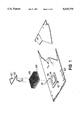
- FIG. 1 shows a top perspective view of a heat sink assembly according to the present invention
- FIG. 2 shows a top view of the heat sink assembly according to the present invention
- FIG. 3 shows a side view of the heat sink assembly according to the present invention
- FIG. 4 shows a top view of a heat sink mounting clamp according to the present invention
- FIG. 5 shows an end view of the heat sink mounting clamp according to the present invention
- FIG. 6 is a side view of the heat sink mounting clamp according to the present invention.
- FIG. 7 is a side view of a notched foot of the heat sink mounting clamp according to the present invention.
- FIG. 1 shows a top perspective view of a heat sink assembly according to the present invention, which comprises an integrated circuit (I.C.) package 114 that is mounted on printed circuit board 120.
- Integrated circuit package 114 has a heat spreader 116 mounted thereon.
- Heat sink 108 which has extruded fins 106 is then mounted on top of the I.C. package 114 or preferably the heat spreader 116.
- a clamp 100 with notched feet 102 and 104 is inserted into a groove between fins 106 of heat sink 108 and clamped to printed circuit board 120 by inserted notched feet 102 and 104 into L-shaped holes 110 and 112 in printed circuit (P.C.) board 120.
- Notched feet 102 and 104 of clamp 100 locked to the edge of P.C. board 120 inside of holes 110 and 112.
- Printed circuit board 120 can be any known printed circuit board material.
- L-shaped holes 110 and 112 are formed in P.C. board 120 during manufacturing when other mounting holes and features are formed in the P.C. board 120. Holes 110 and 112 are preferably located just outside opposing corners of the I.C. package's 114 final position.
- I.C. package 114 can be any size, shape or material I.C. package.
- Heat spreader 116 can be any good thermal conductive material, such as copper. Although heat spreader 116 is not necessary, it is a preferred method of heat dissipation.
- Heat sink 108 can be any known heat spreader that has fins.
- heat sink clamp 100 can be made of any elastic spring material, such as hardened spring steel wire. In a preferred mode, clamp 100 is made of 302 stainless steel wire.
- FIGS. 2 and 4 show a top view of heat sink mounting clamp 100 whereby heat sink mounting clamp 100 forms a Z-shaped pattern.
- Legs 122 and 124 are bent slightly past 90 degrees from central beam 126 such that legs 122 and 124 are bent slightly in the direction of notched feet 102 and 104, respectively.
- This Z shape creates a load such that when legs 122 and 124 are bent inward and released once notched feet 102 and 104 are inside holes 110 and 112 (see FIG. 2), notched feet 102 and 104 lock to an outer edge of holes 110 and 112 in P.C. board 120.
- FIGS. 3 and 5 show an end view of heat sink mounting clamp 100 whereby heat sink mounting clamp 100 forms an M-shaped pattern.
- legs 122 and 124 are bent a few degrees less than 180 degrees.
- This M-shape creates a load such that when legs 122 and 124 are bent downward and notched feet 102 and 104 are locked in holes 110 and 112 (see FIG. 3), heat sink 108 is held securing in place on top of I.C. package 114.
- the Z-M shaped clamp 100 acts as a torsional spring in both the vertical and horizontal directions. Accordingly, clamp 100 holds the heat sink 108 in place on the surface of I.C. package 114.
- the assembly is self-correcting in that the spring force of clamp 100 will force the heat sink into a stable position if the heat sink is slightly displaced.
- FIG. 6 shows a side view of heat sink mounting clamp 100 which shows central beam 126, legs 122 and 124, feet 128 and 130 and notches 102 and 104. Feet 128 and 130 are bent approximately 90 degrees from legs 124 and 130.
- FIG. 7 shows a blown-up view of notch 102, which is C-shaped. Notches 102 and 104 could be L-shaped or other wise hooked at the end to lock with the edges of holes 110 and 112.
- the holes in the printed circuit board could be round, square, C-shaped, etc.
- a frame could be placed under the integrated circuit package that the heat sink clamp attaches to, or the heat sink clamp could lock to an edge of the integrated circuit package.
Abstract
Description
Claims (6)
Priority Applications (1)
| Application Number | Priority Date | Filing Date | Title |
|---|---|---|---|
| US08/315,036 US5615735A (en) | 1994-09-29 | 1994-09-29 | Heat sink spring clamp |
Applications Claiming Priority (1)
| Application Number | Priority Date | Filing Date | Title |
|---|---|---|---|
| US08/315,036 US5615735A (en) | 1994-09-29 | 1994-09-29 | Heat sink spring clamp |
Publications (1)
| Publication Number | Publication Date |
|---|---|
| US5615735A true US5615735A (en) | 1997-04-01 |
Family
ID=23222588
Family Applications (1)
| Application Number | Title | Priority Date | Filing Date |
|---|---|---|---|
| US08/315,036 Expired - Lifetime US5615735A (en) | 1994-09-29 | 1994-09-29 | Heat sink spring clamp |
Country Status (1)
| Country | Link |
|---|---|
| US (1) | US5615735A (en) |
Cited By (45)
| Publication number | Priority date | Publication date | Assignee | Title |
|---|---|---|---|---|
| US5842512A (en) * | 1996-12-31 | 1998-12-01 | International Electronic Research Corporation | Heat sink assembly |
| US5847452A (en) * | 1997-06-30 | 1998-12-08 | Sun Microsystems, Inc. | Post mounted heat sink method and apparatus |
| US5880933A (en) * | 1997-08-18 | 1999-03-09 | Daimlerchrysler Corporation | Heat sinking module cover |
| US5969949A (en) * | 1998-03-31 | 1999-10-19 | Sun Microsystems, Inc. | Interfitting heat sink and heat spreader slug |
| US6029330A (en) * | 1997-09-25 | 2000-02-29 | Hewlett-Packard Company | Tool for compressing a torsional spring for clamping a heat sink |
| US6045653A (en) * | 1998-07-24 | 2000-04-04 | Xemod, Inc. | Glue deposit device for power printed circuit board |
| US6075703A (en) * | 1997-03-26 | 2000-06-13 | Samsung Electronics Co., Ltd. | Heat sink assembly |
| US6079486A (en) * | 1997-02-27 | 2000-06-27 | Aavid Thermal Technologies, Inc. | Spring clip for attaching an electronic component to a heat sink and an assembly utilizing the same |
| US6130821A (en) * | 1998-12-03 | 2000-10-10 | Motorola, Inc. | Multi-chip assembly having a heat sink and method thereof |
| EP1074173A1 (en) * | 1998-04-27 | 2001-02-07 | Aavid Thermal Products, Inc. | Reverse cantilever spring clip |
| US6239972B1 (en) | 1999-12-13 | 2001-05-29 | Honeywell International Inc. | Integrated convection and conduction heat sink for multiple mounting positions |
| US6252772B1 (en) | 1999-02-10 | 2001-06-26 | Micron Technology, Inc. | Removable heat sink bumpers on a quad flat package |
| US6330147B1 (en) * | 1999-11-19 | 2001-12-11 | International Business Machines Corporation | Method and apparatus for mounting components using a Z-spring |
| US6353537B2 (en) * | 1998-12-17 | 2002-03-05 | Canon Kabushiki Kaisha | Structure for mounting radiating plate |
| WO2002097882A1 (en) * | 2001-05-30 | 2002-12-05 | Intel Corporation | A heat dissipation device having a load centering mechanism |
| US6496371B2 (en) * | 2001-03-30 | 2002-12-17 | Intel Corporation | Heat sink mounting method and apparatus |
| US6510054B1 (en) * | 2001-07-20 | 2003-01-21 | Hon Hai Precision Ind. Co., Ltd. | Heat sink clip assembly with handles |
| US6518507B1 (en) * | 2001-07-20 | 2003-02-11 | Hon Hai Precision Ind. Co., Ltd. | Readily attachable heat sink assembly |
| US6541710B1 (en) | 2001-11-16 | 2003-04-01 | Hewlett-Packard Company | Method and apparatus of supporting circuit component having a solder column array using interspersed rigid columns |
| US20030095392A1 (en) * | 2001-11-16 | 2003-05-22 | Deeney Jeffrey L. | Method and apparatus for supporting circuit component having solder column array interconnects using interposed support shims |
| US6600661B1 (en) | 2002-04-08 | 2003-07-29 | Hewlett-Packard Development Company, L.P. | Method and apparatus for supporting a circuit component |
| US20030192672A1 (en) * | 2001-12-10 | 2003-10-16 | Lee Hsieh Kun | Clip for heat sink |
| US20040035606A1 (en) * | 2001-11-16 | 2004-02-26 | Deeney Jeffrey L. | Method and apparatus for supporting a circuit component having solder column interconnects using an external support |
| US20040074630A1 (en) * | 2002-10-18 | 2004-04-22 | Sen Bidyut K. | Conformal heat spreader |
| US6797880B2 (en) * | 2001-06-20 | 2004-09-28 | Siemens Aktiengesellschaft | Plastic frame for the mounting of an electronic heavy-current control unit |
| US6798663B1 (en) * | 2003-04-21 | 2004-09-28 | Hewlett Packard Development Company, L.P. | Heat sink hold-down with fan-module attach location |
| US20040207985A1 (en) * | 2003-04-21 | 2004-10-21 | Delano Andrew D. | Variable-gap thermal-interface device |
| US6809937B2 (en) | 2001-11-16 | 2004-10-26 | Hewlett-Packard Development Company, L.P. | Method and apparatus for shock and vibration isolation of a circuit component |
| US20040223303A1 (en) * | 2003-05-06 | 2004-11-11 | Hornung Craig Warren | Dual material heat sink core assembly |
| US20040226688A1 (en) * | 2003-04-30 | 2004-11-18 | Arthur Fong | Application specific apparatus for dissipating heat from multiple electronic components |
| US20070206359A1 (en) * | 2006-03-05 | 2007-09-06 | Cheng-Tien Lai | Memory module assembly including a clip for mounting a heat sink thereon |
| US20080130243A1 (en) * | 2006-11-30 | 2008-06-05 | Inventec Corporation | Fastening mechanism |
| US20080296461A1 (en) * | 2007-06-03 | 2008-12-04 | Zhi-Wei Tao | Secure device |
| US7518875B2 (en) | 2006-12-14 | 2009-04-14 | International Business Machines Corporation | Securing heat sinks to a device under test |
| US20090141453A1 (en) * | 2007-11-29 | 2009-06-04 | Fu Zhun Precision Industry (Shen Zhen) Co., Ltd. | Heat dissipation device having a clip assembly |
| US20090154109A1 (en) * | 2007-12-14 | 2009-06-18 | Hong Fu Jin Precision Industry (Shenzhen) Co., Ltd. | Heat sink assembly |
| US20090168360A1 (en) * | 2008-01-02 | 2009-07-02 | Harman International Industries, Incorporated | Clamp for electrical devices |
| US20090323289A1 (en) * | 2008-06-27 | 2009-12-31 | Fu Zhun Precision Industry (Shen Zhen) Co., Ltd. | Heat sink assembly |
| US20100319876A1 (en) * | 2007-02-08 | 2010-12-23 | Toyota Jidosha Kabushiki Kaisha | Semiconductor element cooling structure |
| US20120327606A1 (en) * | 2011-06-23 | 2012-12-27 | Hon Hai Precision Industry Co., Ltd. | Wire clip and heat sink assembly using the same |
| US20130100614A1 (en) * | 2011-10-19 | 2013-04-25 | Sercomm Corporation | Electronic device using fastener for fixing |
| US20130120932A1 (en) * | 2011-11-16 | 2013-05-16 | Hon Hai Precision Industry Co., Ltd. | Motherboard with heat sink |
| US20130161074A1 (en) * | 2011-12-22 | 2013-06-27 | Hon Hai Precision Industry Co., Ltd. | Electronic device with heat sink |
| US20140029217A1 (en) * | 2011-06-29 | 2014-01-30 | Mitsubishi Electric Corporation | Electronic device |
| US10672684B2 (en) * | 2018-10-08 | 2020-06-02 | Cisco Technology, Inc. | Heat sink hold down system for direct attachment to printed circuit board |
Citations (19)
| Publication number | Priority date | Publication date | Assignee | Title |
|---|---|---|---|---|
| US3038703A (en) * | 1956-11-13 | 1962-06-12 | Siemens Edison Swan Ltd | Electronic equipment |
| US4679118A (en) * | 1984-08-07 | 1987-07-07 | Aavid Engineering, Inc. | Electronic chip-carrier heat sinks |
| US4745456A (en) * | 1986-09-11 | 1988-05-17 | Thermalloy Incorporated | Heat sink clip assembly |
| JPH02119250A (en) * | 1988-10-28 | 1990-05-07 | Matsushita Electric Ind Co Ltd | Heat-dissipating apparatus |
| US5052474A (en) * | 1990-10-24 | 1991-10-01 | Bronnert Herve X | Hanger assembly for a multiple tube heat exchanger |
| US5168926A (en) * | 1991-09-25 | 1992-12-08 | Intel Corporation | Heat sink design integrating interface material |
| US5208731A (en) * | 1992-01-17 | 1993-05-04 | International Electronic Research Corporation | Heat dissipating assembly |
| JPH05191071A (en) * | 1992-01-14 | 1993-07-30 | Hitachi Ltd | Mounting structure of heat releasing component |
| US5280409A (en) * | 1992-10-09 | 1994-01-18 | Sun Microsystems, Inc. | Heat sink and cover for tab integrated circuits |
| US5287249A (en) * | 1993-07-07 | 1994-02-15 | Global Win Technology Co., Ltd. | Fin assembly for an integrated circuit |
| DE4226816A1 (en) * | 1992-08-13 | 1994-02-17 | Licentia Gmbh | Heat sink for integrated circuit - has metallic heat sink pressed onto flat surface of integrated circuit housing by bow-type spring |
| US5307239A (en) * | 1992-10-08 | 1994-04-26 | Unisys Corporation | Electromechanical module with small footprint and post-solder attachable/removable heat sink frame |
| US5323845A (en) * | 1993-05-17 | 1994-06-28 | Kin Shon Lu | Heat sink clip assembly |
| US5357404A (en) * | 1991-11-18 | 1994-10-18 | The Whitaker Corporation | EMI shield, and assembly using same |
| US5381305A (en) * | 1993-12-22 | 1995-01-10 | Wakefield Engineering, Inc. | Clip for clamping heat sink module to electronic module |
| US5386338A (en) * | 1993-12-20 | 1995-01-31 | Thermalloy, Inc. | Heat sink attachment assembly |
| US5396402A (en) * | 1993-05-24 | 1995-03-07 | Burndy Corporation | Appliance for attaching heat sink to pin grid array and socket |
| US5423375A (en) * | 1994-10-06 | 1995-06-13 | Chiou; Ming D. | CPU heat sink mounting structure |
| US5486981A (en) * | 1994-08-12 | 1996-01-23 | International Electronic Research Corporation | Heat dissipating assembly |
-
1994
- 1994-09-29 US US08/315,036 patent/US5615735A/en not_active Expired - Lifetime
Patent Citations (19)
| Publication number | Priority date | Publication date | Assignee | Title |
|---|---|---|---|---|
| US3038703A (en) * | 1956-11-13 | 1962-06-12 | Siemens Edison Swan Ltd | Electronic equipment |
| US4679118A (en) * | 1984-08-07 | 1987-07-07 | Aavid Engineering, Inc. | Electronic chip-carrier heat sinks |
| US4745456A (en) * | 1986-09-11 | 1988-05-17 | Thermalloy Incorporated | Heat sink clip assembly |
| JPH02119250A (en) * | 1988-10-28 | 1990-05-07 | Matsushita Electric Ind Co Ltd | Heat-dissipating apparatus |
| US5052474A (en) * | 1990-10-24 | 1991-10-01 | Bronnert Herve X | Hanger assembly for a multiple tube heat exchanger |
| US5168926A (en) * | 1991-09-25 | 1992-12-08 | Intel Corporation | Heat sink design integrating interface material |
| US5357404A (en) * | 1991-11-18 | 1994-10-18 | The Whitaker Corporation | EMI shield, and assembly using same |
| JPH05191071A (en) * | 1992-01-14 | 1993-07-30 | Hitachi Ltd | Mounting structure of heat releasing component |
| US5208731A (en) * | 1992-01-17 | 1993-05-04 | International Electronic Research Corporation | Heat dissipating assembly |
| DE4226816A1 (en) * | 1992-08-13 | 1994-02-17 | Licentia Gmbh | Heat sink for integrated circuit - has metallic heat sink pressed onto flat surface of integrated circuit housing by bow-type spring |
| US5307239A (en) * | 1992-10-08 | 1994-04-26 | Unisys Corporation | Electromechanical module with small footprint and post-solder attachable/removable heat sink frame |
| US5280409A (en) * | 1992-10-09 | 1994-01-18 | Sun Microsystems, Inc. | Heat sink and cover for tab integrated circuits |
| US5323845A (en) * | 1993-05-17 | 1994-06-28 | Kin Shon Lu | Heat sink clip assembly |
| US5396402A (en) * | 1993-05-24 | 1995-03-07 | Burndy Corporation | Appliance for attaching heat sink to pin grid array and socket |
| US5287249A (en) * | 1993-07-07 | 1994-02-15 | Global Win Technology Co., Ltd. | Fin assembly for an integrated circuit |
| US5386338A (en) * | 1993-12-20 | 1995-01-31 | Thermalloy, Inc. | Heat sink attachment assembly |
| US5381305A (en) * | 1993-12-22 | 1995-01-10 | Wakefield Engineering, Inc. | Clip for clamping heat sink module to electronic module |
| US5486981A (en) * | 1994-08-12 | 1996-01-23 | International Electronic Research Corporation | Heat dissipating assembly |
| US5423375A (en) * | 1994-10-06 | 1995-06-13 | Chiou; Ming D. | CPU heat sink mounting structure |
Non-Patent Citations (4)
| Title |
|---|
| EG&G Wakefield Engineering, "669 Series SpiderClip™ Heat Sink And Clip Assembly For Intel 80486DX And 80486DX2™ Microprocessors," Bulletin 1204, Sep. 1992, Four pages. |
| EG&G Wakefield Engineering, 669 Series SpiderClip Heat Sink And Clip Assembly For Intel 80486DX And 80486DX2 Microprocessors, Bulletin 1204, Sep. 1992, Four pages. * |
| Thermalloy, Inc., "New Heat Sink Spring Clip For Use With AMP* Low Insertion Force PGA Sockets," Apr., 1993, *AMP is a Trademark of AMP Incorporated. |
| Thermalloy, Inc., New Heat Sink Spring Clip For Use With AMP* Low Insertion Force PGA Sockets, Apr., 1993, *AMP is a Trademark of AMP Incorporated. * |
Cited By (72)
| Publication number | Priority date | Publication date | Assignee | Title |
|---|---|---|---|---|
| US5842512A (en) * | 1996-12-31 | 1998-12-01 | International Electronic Research Corporation | Heat sink assembly |
| US6079486A (en) * | 1997-02-27 | 2000-06-27 | Aavid Thermal Technologies, Inc. | Spring clip for attaching an electronic component to a heat sink and an assembly utilizing the same |
| US6075703A (en) * | 1997-03-26 | 2000-06-13 | Samsung Electronics Co., Ltd. | Heat sink assembly |
| US6209623B1 (en) | 1997-06-30 | 2001-04-03 | Sun Microsystems, Inc. | Post mounted heat sink method and apparatus |
| US5847452A (en) * | 1997-06-30 | 1998-12-08 | Sun Microsystems, Inc. | Post mounted heat sink method and apparatus |
| WO1999000843A1 (en) * | 1997-06-30 | 1999-01-07 | Sun Microsystems, Inc. | Post mounted heat sink method and apparatus |
| US5880933A (en) * | 1997-08-18 | 1999-03-09 | Daimlerchrysler Corporation | Heat sinking module cover |
| US6029330A (en) * | 1997-09-25 | 2000-02-29 | Hewlett-Packard Company | Tool for compressing a torsional spring for clamping a heat sink |
| US5969949A (en) * | 1998-03-31 | 1999-10-19 | Sun Microsystems, Inc. | Interfitting heat sink and heat spreader slug |
| EP1074173A1 (en) * | 1998-04-27 | 2001-02-07 | Aavid Thermal Products, Inc. | Reverse cantilever spring clip |
| EP1074173A4 (en) * | 1998-04-27 | 2002-05-15 | Aavid Thermal Products Inc | Reverse cantilever spring clip |
| US6045653A (en) * | 1998-07-24 | 2000-04-04 | Xemod, Inc. | Glue deposit device for power printed circuit board |
| US6130821A (en) * | 1998-12-03 | 2000-10-10 | Motorola, Inc. | Multi-chip assembly having a heat sink and method thereof |
| US6353537B2 (en) * | 1998-12-17 | 2002-03-05 | Canon Kabushiki Kaisha | Structure for mounting radiating plate |
| US6252772B1 (en) | 1999-02-10 | 2001-06-26 | Micron Technology, Inc. | Removable heat sink bumpers on a quad flat package |
| US6349034B2 (en) | 1999-02-10 | 2002-02-19 | Micron Technology, Inc. | Removable heat sink bumpers on a quad flat package |
| US6330147B1 (en) * | 1999-11-19 | 2001-12-11 | International Business Machines Corporation | Method and apparatus for mounting components using a Z-spring |
| US6239972B1 (en) | 1999-12-13 | 2001-05-29 | Honeywell International Inc. | Integrated convection and conduction heat sink for multiple mounting positions |
| US6496371B2 (en) * | 2001-03-30 | 2002-12-17 | Intel Corporation | Heat sink mounting method and apparatus |
| WO2002097882A1 (en) * | 2001-05-30 | 2002-12-05 | Intel Corporation | A heat dissipation device having a load centering mechanism |
| US20040212079A1 (en) * | 2001-05-30 | 2004-10-28 | Winkel Casey R. | Heat dissipation device having a load centering mechanism |
| US6803652B2 (en) | 2001-05-30 | 2004-10-12 | Intel Corporation | Heat dissipation device having a load centering mechanism |
| US6797880B2 (en) * | 2001-06-20 | 2004-09-28 | Siemens Aktiengesellschaft | Plastic frame for the mounting of an electronic heavy-current control unit |
| US6510054B1 (en) * | 2001-07-20 | 2003-01-21 | Hon Hai Precision Ind. Co., Ltd. | Heat sink clip assembly with handles |
| US6518507B1 (en) * | 2001-07-20 | 2003-02-11 | Hon Hai Precision Ind. Co., Ltd. | Readily attachable heat sink assembly |
| US6809937B2 (en) | 2001-11-16 | 2004-10-26 | Hewlett-Packard Development Company, L.P. | Method and apparatus for shock and vibration isolation of a circuit component |
| US20050017349A1 (en) * | 2001-11-16 | 2005-01-27 | Deeney Jeffrey L. | Method for supporting circuit component having solder column array interconnects using interposed support shims |
| US6710264B2 (en) | 2001-11-16 | 2004-03-23 | Hewlett-Packard Development Company, L.P. | Method and apparatus for supporting a circuit component having solder column interconnects using external support |
| US20040035606A1 (en) * | 2001-11-16 | 2004-02-26 | Deeney Jeffrey L. | Method and apparatus for supporting a circuit component having solder column interconnects using an external support |
| US7185423B2 (en) | 2001-11-16 | 2007-03-06 | Hewlett-Packard Development Company, L.P. | Method of a supporting a CGA integrated package on a circuit board with improved shock and vibration isolation |
| US20050022375A1 (en) * | 2001-11-16 | 2005-02-03 | Augustin Thomas J. | Method and apparatus for shock and vibration isolation of a circuit component |
| US7434309B2 (en) | 2001-11-16 | 2008-10-14 | Hewlett-Packard Development Company, L.P. | Method and apparatus for supporting a circuit component having solder column interconnects using an external support |
| US6813162B2 (en) | 2001-11-16 | 2004-11-02 | Hewlett-Packard Development Company, L.P. | Method and apparatus for supporting circuit component having solder column array interconnects using interposed support shims |
| US6541710B1 (en) | 2001-11-16 | 2003-04-01 | Hewlett-Packard Company | Method and apparatus of supporting circuit component having a solder column array using interspersed rigid columns |
| US20030095392A1 (en) * | 2001-11-16 | 2003-05-22 | Deeney Jeffrey L. | Method and apparatus for supporting circuit component having solder column array interconnects using interposed support shims |
| US20030192672A1 (en) * | 2001-12-10 | 2003-10-16 | Lee Hsieh Kun | Clip for heat sink |
| US7055589B2 (en) * | 2001-12-10 | 2006-06-06 | Hon Hai Precision Ind. Co., Ltd. | Clip for heat sink |
| US6600661B1 (en) | 2002-04-08 | 2003-07-29 | Hewlett-Packard Development Company, L.P. | Method and apparatus for supporting a circuit component |
| US7007741B2 (en) | 2002-10-18 | 2006-03-07 | Sun Microsystems, Inc. | Conformal heat spreader |
| WO2004036645A3 (en) * | 2002-10-18 | 2004-06-03 | Sun Microsystems Inc | Conformal heat spreader |
| WO2004036645A2 (en) * | 2002-10-18 | 2004-04-29 | Sun Microsystems, Inc. | Conformal heat spreader |
| US20040074630A1 (en) * | 2002-10-18 | 2004-04-22 | Sen Bidyut K. | Conformal heat spreader |
| US6798663B1 (en) * | 2003-04-21 | 2004-09-28 | Hewlett Packard Development Company, L.P. | Heat sink hold-down with fan-module attach location |
| US20040207986A1 (en) * | 2003-04-21 | 2004-10-21 | Rubenstein Brandon A. | Heat sink hold-down with fan-module attach location |
| US20040207985A1 (en) * | 2003-04-21 | 2004-10-21 | Delano Andrew D. | Variable-gap thermal-interface device |
| US7480143B2 (en) | 2003-04-21 | 2009-01-20 | Hewlett-Packard Development Company, L.P. | Variable-gap thermal-interface device |
| US20040226688A1 (en) * | 2003-04-30 | 2004-11-18 | Arthur Fong | Application specific apparatus for dissipating heat from multiple electronic components |
| US20040223303A1 (en) * | 2003-05-06 | 2004-11-11 | Hornung Craig Warren | Dual material heat sink core assembly |
| US6977814B2 (en) * | 2003-05-06 | 2005-12-20 | Tyco Electronics Corporation | Dual material heat sink core assembly |
| US7333338B2 (en) * | 2006-03-05 | 2008-02-19 | Fu Zhun Precison Industry (Shen Zhen) Co., Ltd. | Memory module assembly including a clip for mounting a heat sink thereon |
| US20070206359A1 (en) * | 2006-03-05 | 2007-09-06 | Cheng-Tien Lai | Memory module assembly including a clip for mounting a heat sink thereon |
| US20080130243A1 (en) * | 2006-11-30 | 2008-06-05 | Inventec Corporation | Fastening mechanism |
| US7697299B2 (en) * | 2006-12-14 | 2010-04-13 | International Business Machines Corporation | Apparatus for securing heat sinks to a device under test |
| US7518875B2 (en) | 2006-12-14 | 2009-04-14 | International Business Machines Corporation | Securing heat sinks to a device under test |
| US20090103270A1 (en) * | 2006-12-14 | 2009-04-23 | International Business Machines Corporation | Apparatus for securing heat sinks to a device under test |
| US8919424B2 (en) * | 2007-02-08 | 2014-12-30 | Toyota Jidosha Kabushiki Kaisha | Semiconductor element cooling structure |
| US20100319876A1 (en) * | 2007-02-08 | 2010-12-23 | Toyota Jidosha Kabushiki Kaisha | Semiconductor element cooling structure |
| US20080296461A1 (en) * | 2007-06-03 | 2008-12-04 | Zhi-Wei Tao | Secure device |
| US20090141453A1 (en) * | 2007-11-29 | 2009-06-04 | Fu Zhun Precision Industry (Shen Zhen) Co., Ltd. | Heat dissipation device having a clip assembly |
| US7697297B2 (en) * | 2007-11-29 | 2010-04-13 | Fu Zhun Precision Industry (Shen Zhen) Co., Ltd. | Heat dissipation device having a clip assembly |
| US20090154109A1 (en) * | 2007-12-14 | 2009-06-18 | Hong Fu Jin Precision Industry (Shenzhen) Co., Ltd. | Heat sink assembly |
| US7746653B2 (en) | 2008-01-02 | 2010-06-29 | Harman International Industries Incorporated | Clamp for electrical devices |
| US20090168360A1 (en) * | 2008-01-02 | 2009-07-02 | Harman International Industries, Incorporated | Clamp for electrical devices |
| US7672136B2 (en) * | 2008-06-27 | 2010-03-02 | Fu Zhun Precision Industry (Shen Zhen) Co., Ltd. | Heat sink assembly |
| US20090323289A1 (en) * | 2008-06-27 | 2009-12-31 | Fu Zhun Precision Industry (Shen Zhen) Co., Ltd. | Heat sink assembly |
| US20120327606A1 (en) * | 2011-06-23 | 2012-12-27 | Hon Hai Precision Industry Co., Ltd. | Wire clip and heat sink assembly using the same |
| US20140029217A1 (en) * | 2011-06-29 | 2014-01-30 | Mitsubishi Electric Corporation | Electronic device |
| US8982564B2 (en) * | 2011-06-29 | 2015-03-17 | Mitsubishi Electric Corporation | Electronic device |
| US20130100614A1 (en) * | 2011-10-19 | 2013-04-25 | Sercomm Corporation | Electronic device using fastener for fixing |
| US20130120932A1 (en) * | 2011-11-16 | 2013-05-16 | Hon Hai Precision Industry Co., Ltd. | Motherboard with heat sink |
| US20130161074A1 (en) * | 2011-12-22 | 2013-06-27 | Hon Hai Precision Industry Co., Ltd. | Electronic device with heat sink |
| US10672684B2 (en) * | 2018-10-08 | 2020-06-02 | Cisco Technology, Inc. | Heat sink hold down system for direct attachment to printed circuit board |
Similar Documents
| Publication | Publication Date | Title |
|---|---|---|
| US5615735A (en) | Heat sink spring clamp | |
| US5594623A (en) | Method and apparatus for attaching a heat sink and a fan to an integrated circuit package | |
| US5329426A (en) | Clip-on heat sink | |
| US5463529A (en) | High power dissipating packages with matched heatspreader heatsink assemblies | |
| US5754400A (en) | Demountable heat sink | |
| US6212070B1 (en) | Zero force heat sink | |
| US6331937B1 (en) | Apparatus and method for securing a heat sink to an electronic component in a computer system | |
| US7095614B2 (en) | Electronic module assembly | |
| US6518507B1 (en) | Readily attachable heat sink assembly | |
| US5883782A (en) | Apparatus for attaching a heat sink to a PCB mounted semiconductor package | |
| US6067230A (en) | Electronic device with heat radiation members | |
| US6195880B1 (en) | Strap spring for attaching heat sinks to circuit boards | |
| JP2009516371A (en) | Cooling structure | |
| US6992893B2 (en) | Heat sink attachment | |
| WO2002035901A1 (en) | Apparatus for providing heat dissipation for a circuit element | |
| US6538320B1 (en) | Heat spreader having holes for rivet-like adhesive connections | |
| US20040124517A1 (en) | Structural reinforcement for electronic substrate | |
| US7203065B1 (en) | Heatsink assembly | |
| US20040109301A1 (en) | Cooling device for an integrated circuit | |
| JP2005026683A (en) | Method for supporting circuit package and electronic component system | |
| US6829144B1 (en) | Flip chip package with heat spreader allowing multiple heat sink attachment | |
| US7434309B2 (en) | Method and apparatus for supporting a circuit component having solder column interconnects using an external support | |
| US6813162B2 (en) | Method and apparatus for supporting circuit component having solder column array interconnects using interposed support shims | |
| CN115379700A (en) | Single board, electronic device and manufacturing method | |
| JP3750427B2 (en) | Semiconductor device |
Legal Events
| Date | Code | Title | Description |
|---|---|---|---|
| AS | Assignment |
Owner name: HEWLETT-PACKARD COMPANY Free format text: ASSIGNMENT OF ASSIGNORS INTEREST;ASSIGNORS:YOSHIDA, STUART;SEADER, REX;NEISEN, STEPHEN P.;REEL/FRAME:007402/0399 Effective date: 19940929 |
|
| STCF | Information on status: patent grant |
Free format text: PATENTED CASE |
|
| FEPP | Fee payment procedure |
Free format text: PAYOR NUMBER ASSIGNED (ORIGINAL EVENT CODE: ASPN); ENTITY STATUS OF PATENT OWNER: LARGE ENTITY |
|
| FPAY | Fee payment |
Year of fee payment: 4 |
|
| AS | Assignment |
Owner name: HEWLETT-PACKARD COMPANY, COLORADO Free format text: MERGER;ASSIGNOR:HEWLETT-PACKARD COMPANY;REEL/FRAME:011523/0469 Effective date: 19980520 |
|
| FPAY | Fee payment |
Year of fee payment: 8 |
|
| FPAY | Fee payment |
Year of fee payment: 12 |
|
| AS | Assignment |
Owner name: HEWLETT-PACKARD DEVELOPMENT COMPANY, L.P., TEXAS Free format text: ASSIGNMENT OF ASSIGNORS INTEREST;ASSIGNOR:HEWLETT-PACKARD COMPANY;REEL/FRAME:026945/0699 Effective date: 20030131 |