US5616520A - Semiconductor integrated circuit device and fabrication method thereof - Google Patents
Semiconductor integrated circuit device and fabrication method thereof Download PDFInfo
- Publication number
- US5616520A US5616520A US08/367,490 US36749094A US5616520A US 5616520 A US5616520 A US 5616520A US 36749094 A US36749094 A US 36749094A US 5616520 A US5616520 A US 5616520A
- Authority
- US
- United States
- Prior art keywords
- balls
- semiconductor chip
- integrated circuit
- circuit device
- bonding
- Prior art date
- Legal status (The legal status is an assumption and is not a legal conclusion. Google has not performed a legal analysis and makes no representation as to the accuracy of the status listed.)
- Expired - Lifetime
Links
Images


Classifications
-
- H—ELECTRICITY
- H01—ELECTRIC ELEMENTS
- H01L—SEMICONDUCTOR DEVICES NOT COVERED BY CLASS H10
- H01L24/00—Arrangements for connecting or disconnecting semiconductor or solid-state bodies; Methods or apparatus related thereto
- H01L24/01—Means for bonding being attached to, or being formed on, the surface to be connected, e.g. chip-to-package, die-attach, "first-level" interconnects; Manufacturing methods related thereto
- H01L24/10—Bump connectors ; Manufacturing methods related thereto
- H01L24/15—Structure, shape, material or disposition of the bump connectors after the connecting process
- H01L24/16—Structure, shape, material or disposition of the bump connectors after the connecting process of an individual bump connector
-
- H—ELECTRICITY
- H01—ELECTRIC ELEMENTS
- H01L—SEMICONDUCTOR DEVICES NOT COVERED BY CLASS H10
- H01L23/00—Details of semiconductor or other solid state devices
- H01L23/02—Containers; Seals
- H01L23/10—Containers; Seals characterised by the material or arrangement of seals between parts, e.g. between cap and base of the container or between leads and walls of the container
-
- H—ELECTRICITY
- H01—ELECTRIC ELEMENTS
- H01L—SEMICONDUCTOR DEVICES NOT COVERED BY CLASS H10
- H01L23/00—Details of semiconductor or other solid state devices
- H01L23/34—Arrangements for cooling, heating, ventilating or temperature compensation ; Temperature sensing arrangements
- H01L23/36—Selection of materials, or shaping, to facilitate cooling or heating, e.g. heatsinks
- H01L23/367—Cooling facilitated by shape of device
- H01L23/3672—Foil-like cooling fins or heat sinks
-
- H—ELECTRICITY
- H01—ELECTRIC ELEMENTS
- H01L—SEMICONDUCTOR DEVICES NOT COVERED BY CLASS H10
- H01L23/00—Details of semiconductor or other solid state devices
- H01L23/34—Arrangements for cooling, heating, ventilating or temperature compensation ; Temperature sensing arrangements
- H01L23/36—Selection of materials, or shaping, to facilitate cooling or heating, e.g. heatsinks
- H01L23/367—Cooling facilitated by shape of device
- H01L23/3677—Wire-like or pin-like cooling fins or heat sinks
-
- H—ELECTRICITY
- H01—ELECTRIC ELEMENTS
- H01L—SEMICONDUCTOR DEVICES NOT COVERED BY CLASS H10
- H01L23/00—Details of semiconductor or other solid state devices
- H01L23/34—Arrangements for cooling, heating, ventilating or temperature compensation ; Temperature sensing arrangements
- H01L23/42—Fillings or auxiliary members in containers or encapsulations selected or arranged to facilitate heating or cooling
- H01L23/433—Auxiliary members in containers characterised by their shape, e.g. pistons
-
- H—ELECTRICITY
- H01—ELECTRIC ELEMENTS
- H01L—SEMICONDUCTOR DEVICES NOT COVERED BY CLASS H10
- H01L23/00—Details of semiconductor or other solid state devices
- H01L23/58—Structural electrical arrangements for semiconductor devices not otherwise provided for, e.g. in combination with batteries
- H01L23/64—Impedance arrangements
- H01L23/66—High-frequency adaptations
-
- H—ELECTRICITY
- H01—ELECTRIC ELEMENTS
- H01L—SEMICONDUCTOR DEVICES NOT COVERED BY CLASS H10
- H01L24/00—Arrangements for connecting or disconnecting semiconductor or solid-state bodies; Methods or apparatus related thereto
- H01L24/01—Means for bonding being attached to, or being formed on, the surface to be connected, e.g. chip-to-package, die-attach, "first-level" interconnects; Manufacturing methods related thereto
- H01L24/10—Bump connectors ; Manufacturing methods related thereto
- H01L24/11—Manufacturing methods
-
- H—ELECTRICITY
- H01—ELECTRIC ELEMENTS
- H01L—SEMICONDUCTOR DEVICES NOT COVERED BY CLASS H10
- H01L24/00—Arrangements for connecting or disconnecting semiconductor or solid-state bodies; Methods or apparatus related thereto
- H01L24/01—Means for bonding being attached to, or being formed on, the surface to be connected, e.g. chip-to-package, die-attach, "first-level" interconnects; Manufacturing methods related thereto
- H01L24/10—Bump connectors ; Manufacturing methods related thereto
- H01L24/12—Structure, shape, material or disposition of the bump connectors prior to the connecting process
- H01L24/13—Structure, shape, material or disposition of the bump connectors prior to the connecting process of an individual bump connector
-
- H—ELECTRICITY
- H01—ELECTRIC ELEMENTS
- H01L—SEMICONDUCTOR DEVICES NOT COVERED BY CLASS H10
- H01L24/00—Arrangements for connecting or disconnecting semiconductor or solid-state bodies; Methods or apparatus related thereto
- H01L24/74—Apparatus for manufacturing arrangements for connecting or disconnecting semiconductor or solid-state bodies
- H01L24/75—Apparatus for connecting with bump connectors or layer connectors
-
- H—ELECTRICITY
- H01—ELECTRIC ELEMENTS
- H01L—SEMICONDUCTOR DEVICES NOT COVERED BY CLASS H10
- H01L24/00—Arrangements for connecting or disconnecting semiconductor or solid-state bodies; Methods or apparatus related thereto
- H01L24/80—Methods for connecting semiconductor or other solid state bodies using means for bonding being attached to, or being formed on, the surface to be connected
- H01L24/81—Methods for connecting semiconductor or other solid state bodies using means for bonding being attached to, or being formed on, the surface to be connected using a bump connector
-
- H—ELECTRICITY
- H01—ELECTRIC ELEMENTS
- H01L—SEMICONDUCTOR DEVICES NOT COVERED BY CLASS H10
- H01L2224/00—Indexing scheme for arrangements for connecting or disconnecting semiconductor or solid-state bodies and methods related thereto as covered by H01L24/00
- H01L2224/01—Means for bonding being attached to, or being formed on, the surface to be connected, e.g. chip-to-package, die-attach, "first-level" interconnects; Manufacturing methods related thereto
- H01L2224/02—Bonding areas; Manufacturing methods related thereto
- H01L2224/04—Structure, shape, material or disposition of the bonding areas prior to the connecting process
- H01L2224/05—Structure, shape, material or disposition of the bonding areas prior to the connecting process of an individual bonding area
- H01L2224/0554—External layer
- H01L2224/05599—Material
- H01L2224/056—Material with a principal constituent of the material being a metal or a metalloid, e.g. boron [B], silicon [Si], germanium [Ge], arsenic [As], antimony [Sb], tellurium [Te] and polonium [Po], and alloys thereof
- H01L2224/05638—Material with a principal constituent of the material being a metal or a metalloid, e.g. boron [B], silicon [Si], germanium [Ge], arsenic [As], antimony [Sb], tellurium [Te] and polonium [Po], and alloys thereof the principal constituent melting at a temperature of greater than or equal to 950°C and less than 1550°C
- H01L2224/05644—Gold [Au] as principal constituent
-
- H—ELECTRICITY
- H01—ELECTRIC ELEMENTS
- H01L—SEMICONDUCTOR DEVICES NOT COVERED BY CLASS H10
- H01L2224/00—Indexing scheme for arrangements for connecting or disconnecting semiconductor or solid-state bodies and methods related thereto as covered by H01L24/00
- H01L2224/01—Means for bonding being attached to, or being formed on, the surface to be connected, e.g. chip-to-package, die-attach, "first-level" interconnects; Manufacturing methods related thereto
- H01L2224/02—Bonding areas; Manufacturing methods related thereto
- H01L2224/04—Structure, shape, material or disposition of the bonding areas prior to the connecting process
- H01L2224/06—Structure, shape, material or disposition of the bonding areas prior to the connecting process of a plurality of bonding areas
- H01L2224/061—Disposition
- H01L2224/0612—Layout
- H01L2224/0613—Square or rectangular array
- H01L2224/06131—Square or rectangular array being uniform, i.e. having a uniform pitch across the array
-
- H—ELECTRICITY
- H01—ELECTRIC ELEMENTS
- H01L—SEMICONDUCTOR DEVICES NOT COVERED BY CLASS H10
- H01L2224/00—Indexing scheme for arrangements for connecting or disconnecting semiconductor or solid-state bodies and methods related thereto as covered by H01L24/00
- H01L2224/01—Means for bonding being attached to, or being formed on, the surface to be connected, e.g. chip-to-package, die-attach, "first-level" interconnects; Manufacturing methods related thereto
- H01L2224/10—Bump connectors; Manufacturing methods related thereto
- H01L2224/11—Manufacturing methods
- H01L2224/113—Manufacturing methods by local deposition of the material of the bump connector
- H01L2224/1133—Manufacturing methods by local deposition of the material of the bump connector in solid form
- H01L2224/1134—Stud bumping, i.e. using a wire-bonding apparatus
-
- H—ELECTRICITY
- H01—ELECTRIC ELEMENTS
- H01L—SEMICONDUCTOR DEVICES NOT COVERED BY CLASS H10
- H01L2224/00—Indexing scheme for arrangements for connecting or disconnecting semiconductor or solid-state bodies and methods related thereto as covered by H01L24/00
- H01L2224/01—Means for bonding being attached to, or being formed on, the surface to be connected, e.g. chip-to-package, die-attach, "first-level" interconnects; Manufacturing methods related thereto
- H01L2224/10—Bump connectors; Manufacturing methods related thereto
- H01L2224/11—Manufacturing methods
- H01L2224/118—Post-treatment of the bump connector
- H01L2224/1183—Reworking, e.g. shaping
- H01L2224/1184—Reworking, e.g. shaping involving a mechanical process, e.g. planarising the bump connector
-
- H—ELECTRICITY
- H01—ELECTRIC ELEMENTS
- H01L—SEMICONDUCTOR DEVICES NOT COVERED BY CLASS H10
- H01L2224/00—Indexing scheme for arrangements for connecting or disconnecting semiconductor or solid-state bodies and methods related thereto as covered by H01L24/00
- H01L2224/01—Means for bonding being attached to, or being formed on, the surface to be connected, e.g. chip-to-package, die-attach, "first-level" interconnects; Manufacturing methods related thereto
- H01L2224/10—Bump connectors; Manufacturing methods related thereto
- H01L2224/12—Structure, shape, material or disposition of the bump connectors prior to the connecting process
- H01L2224/13—Structure, shape, material or disposition of the bump connectors prior to the connecting process of an individual bump connector
- H01L2224/13001—Core members of the bump connector
- H01L2224/13075—Plural core members
- H01L2224/1308—Plural core members being stacked
-
- H—ELECTRICITY
- H01—ELECTRIC ELEMENTS
- H01L—SEMICONDUCTOR DEVICES NOT COVERED BY CLASS H10
- H01L2224/00—Indexing scheme for arrangements for connecting or disconnecting semiconductor or solid-state bodies and methods related thereto as covered by H01L24/00
- H01L2224/01—Means for bonding being attached to, or being formed on, the surface to be connected, e.g. chip-to-package, die-attach, "first-level" interconnects; Manufacturing methods related thereto
- H01L2224/10—Bump connectors; Manufacturing methods related thereto
- H01L2224/12—Structure, shape, material or disposition of the bump connectors prior to the connecting process
- H01L2224/13—Structure, shape, material or disposition of the bump connectors prior to the connecting process of an individual bump connector
- H01L2224/13001—Core members of the bump connector
- H01L2224/13099—Material
- H01L2224/131—Material with a principal constituent of the material being a metal or a metalloid, e.g. boron [B], silicon [Si], germanium [Ge], arsenic [As], antimony [Sb], tellurium [Te] and polonium [Po], and alloys thereof
- H01L2224/13138—Material with a principal constituent of the material being a metal or a metalloid, e.g. boron [B], silicon [Si], germanium [Ge], arsenic [As], antimony [Sb], tellurium [Te] and polonium [Po], and alloys thereof the principal constituent melting at a temperature of greater than or equal to 950°C and less than 1550°C
- H01L2224/13144—Gold [Au] as principal constituent
-
- H—ELECTRICITY
- H01—ELECTRIC ELEMENTS
- H01L—SEMICONDUCTOR DEVICES NOT COVERED BY CLASS H10
- H01L2224/00—Indexing scheme for arrangements for connecting or disconnecting semiconductor or solid-state bodies and methods related thereto as covered by H01L24/00
- H01L2224/01—Means for bonding being attached to, or being formed on, the surface to be connected, e.g. chip-to-package, die-attach, "first-level" interconnects; Manufacturing methods related thereto
- H01L2224/10—Bump connectors; Manufacturing methods related thereto
- H01L2224/15—Structure, shape, material or disposition of the bump connectors after the connecting process
- H01L2224/16—Structure, shape, material or disposition of the bump connectors after the connecting process of an individual bump connector
- H01L2224/161—Disposition
- H01L2224/16151—Disposition the bump connector connecting between a semiconductor or solid-state body and an item not being a semiconductor or solid-state body, e.g. chip-to-substrate, chip-to-passive
- H01L2224/16221—Disposition the bump connector connecting between a semiconductor or solid-state body and an item not being a semiconductor or solid-state body, e.g. chip-to-substrate, chip-to-passive the body and the item being stacked
- H01L2224/16225—Disposition the bump connector connecting between a semiconductor or solid-state body and an item not being a semiconductor or solid-state body, e.g. chip-to-substrate, chip-to-passive the body and the item being stacked the item being non-metallic, e.g. insulating substrate with or without metallisation
- H01L2224/16235—Disposition the bump connector connecting between a semiconductor or solid-state body and an item not being a semiconductor or solid-state body, e.g. chip-to-substrate, chip-to-passive the body and the item being stacked the item being non-metallic, e.g. insulating substrate with or without metallisation the bump connector connecting to a via metallisation of the item
-
- H—ELECTRICITY
- H01—ELECTRIC ELEMENTS
- H01L—SEMICONDUCTOR DEVICES NOT COVERED BY CLASS H10
- H01L2224/00—Indexing scheme for arrangements for connecting or disconnecting semiconductor or solid-state bodies and methods related thereto as covered by H01L24/00
- H01L2224/01—Means for bonding being attached to, or being formed on, the surface to be connected, e.g. chip-to-package, die-attach, "first-level" interconnects; Manufacturing methods related thereto
- H01L2224/42—Wire connectors; Manufacturing methods related thereto
- H01L2224/44—Structure, shape, material or disposition of the wire connectors prior to the connecting process
- H01L2224/45—Structure, shape, material or disposition of the wire connectors prior to the connecting process of an individual wire connector
- H01L2224/45001—Core members of the connector
- H01L2224/45099—Material
- H01L2224/451—Material with a principal constituent of the material being a metal or a metalloid, e.g. boron (B), silicon (Si), germanium (Ge), arsenic (As), antimony (Sb), tellurium (Te) and polonium (Po), and alloys thereof
- H01L2224/45138—Material with a principal constituent of the material being a metal or a metalloid, e.g. boron (B), silicon (Si), germanium (Ge), arsenic (As), antimony (Sb), tellurium (Te) and polonium (Po), and alloys thereof the principal constituent melting at a temperature of greater than or equal to 950°C and less than 1550°C
- H01L2224/45144—Gold (Au) as principal constituent
-
- H—ELECTRICITY
- H01—ELECTRIC ELEMENTS
- H01L—SEMICONDUCTOR DEVICES NOT COVERED BY CLASS H10
- H01L2224/00—Indexing scheme for arrangements for connecting or disconnecting semiconductor or solid-state bodies and methods related thereto as covered by H01L24/00
- H01L2224/73—Means for bonding being of different types provided for in two or more of groups H01L2224/10, H01L2224/18, H01L2224/26, H01L2224/34, H01L2224/42, H01L2224/50, H01L2224/63, H01L2224/71
- H01L2224/732—Location after the connecting process
- H01L2224/73251—Location after the connecting process on different surfaces
- H01L2224/73253—Bump and layer connectors
-
- H—ELECTRICITY
- H01—ELECTRIC ELEMENTS
- H01L—SEMICONDUCTOR DEVICES NOT COVERED BY CLASS H10
- H01L2224/00—Indexing scheme for arrangements for connecting or disconnecting semiconductor or solid-state bodies and methods related thereto as covered by H01L24/00
- H01L2224/74—Apparatus for manufacturing arrangements for connecting or disconnecting semiconductor or solid-state bodies and for methods related thereto
- H01L2224/741—Apparatus for manufacturing means for bonding, e.g. connectors
- H01L2224/749—Tools for reworking, e.g. for shaping
-
- H—ELECTRICITY
- H01—ELECTRIC ELEMENTS
- H01L—SEMICONDUCTOR DEVICES NOT COVERED BY CLASS H10
- H01L2224/00—Indexing scheme for arrangements for connecting or disconnecting semiconductor or solid-state bodies and methods related thereto as covered by H01L24/00
- H01L2224/74—Apparatus for manufacturing arrangements for connecting or disconnecting semiconductor or solid-state bodies and for methods related thereto
- H01L2224/75—Apparatus for connecting with bump connectors or layer connectors
- H01L2224/757—Means for aligning
- H01L2224/75753—Means for optical alignment, e.g. sensors
-
- H—ELECTRICITY
- H01—ELECTRIC ELEMENTS
- H01L—SEMICONDUCTOR DEVICES NOT COVERED BY CLASS H10
- H01L2224/00—Indexing scheme for arrangements for connecting or disconnecting semiconductor or solid-state bodies and methods related thereto as covered by H01L24/00
- H01L2224/74—Apparatus for manufacturing arrangements for connecting or disconnecting semiconductor or solid-state bodies and for methods related thereto
- H01L2224/78—Apparatus for connecting with wire connectors
- H01L2224/7825—Means for applying energy, e.g. heating means
- H01L2224/783—Means for applying energy, e.g. heating means by means of pressure
- H01L2224/78301—Capillary
-
- H—ELECTRICITY
- H01—ELECTRIC ELEMENTS
- H01L—SEMICONDUCTOR DEVICES NOT COVERED BY CLASS H10
- H01L2224/00—Indexing scheme for arrangements for connecting or disconnecting semiconductor or solid-state bodies and methods related thereto as covered by H01L24/00
- H01L2224/80—Methods for connecting semiconductor or other solid state bodies using means for bonding being attached to, or being formed on, the surface to be connected
- H01L2224/81—Methods for connecting semiconductor or other solid state bodies using means for bonding being attached to, or being formed on, the surface to be connected using a bump connector
- H01L2224/8119—Arrangement of the bump connectors prior to mounting
- H01L2224/81193—Arrangement of the bump connectors prior to mounting wherein the bump connectors are disposed on both the semiconductor or solid-state body and another item or body to be connected to the semiconductor or solid-state body
-
- H—ELECTRICITY
- H01—ELECTRIC ELEMENTS
- H01L—SEMICONDUCTOR DEVICES NOT COVERED BY CLASS H10
- H01L2224/00—Indexing scheme for arrangements for connecting or disconnecting semiconductor or solid-state bodies and methods related thereto as covered by H01L24/00
- H01L2224/80—Methods for connecting semiconductor or other solid state bodies using means for bonding being attached to, or being formed on, the surface to be connected
- H01L2224/81—Methods for connecting semiconductor or other solid state bodies using means for bonding being attached to, or being formed on, the surface to be connected using a bump connector
- H01L2224/812—Applying energy for connecting
- H01L2224/81201—Compression bonding
- H01L2224/81208—Compression bonding applying unidirectional static pressure
-
- H—ELECTRICITY
- H01—ELECTRIC ELEMENTS
- H01L—SEMICONDUCTOR DEVICES NOT COVERED BY CLASS H10
- H01L2224/00—Indexing scheme for arrangements for connecting or disconnecting semiconductor or solid-state bodies and methods related thereto as covered by H01L24/00
- H01L2224/80—Methods for connecting semiconductor or other solid state bodies using means for bonding being attached to, or being formed on, the surface to be connected
- H01L2224/81—Methods for connecting semiconductor or other solid state bodies using means for bonding being attached to, or being formed on, the surface to be connected using a bump connector
- H01L2224/818—Bonding techniques
- H01L2224/81801—Soldering or alloying
-
- H—ELECTRICITY
- H01—ELECTRIC ELEMENTS
- H01L—SEMICONDUCTOR DEVICES NOT COVERED BY CLASS H10
- H01L24/00—Arrangements for connecting or disconnecting semiconductor or solid-state bodies; Methods or apparatus related thereto
- H01L24/01—Means for bonding being attached to, or being formed on, the surface to be connected, e.g. chip-to-package, die-attach, "first-level" interconnects; Manufacturing methods related thereto
- H01L24/02—Bonding areas ; Manufacturing methods related thereto
- H01L24/04—Structure, shape, material or disposition of the bonding areas prior to the connecting process
- H01L24/05—Structure, shape, material or disposition of the bonding areas prior to the connecting process of an individual bonding area
-
- H—ELECTRICITY
- H01—ELECTRIC ELEMENTS
- H01L—SEMICONDUCTOR DEVICES NOT COVERED BY CLASS H10
- H01L2924/00—Indexing scheme for arrangements or methods for connecting or disconnecting semiconductor or solid-state bodies as covered by H01L24/00
- H01L2924/01—Chemical elements
- H01L2924/01005—Boron [B]
-
- H—ELECTRICITY
- H01—ELECTRIC ELEMENTS
- H01L—SEMICONDUCTOR DEVICES NOT COVERED BY CLASS H10
- H01L2924/00—Indexing scheme for arrangements or methods for connecting or disconnecting semiconductor or solid-state bodies as covered by H01L24/00
- H01L2924/01—Chemical elements
- H01L2924/01006—Carbon [C]
-
- H—ELECTRICITY
- H01—ELECTRIC ELEMENTS
- H01L—SEMICONDUCTOR DEVICES NOT COVERED BY CLASS H10
- H01L2924/00—Indexing scheme for arrangements or methods for connecting or disconnecting semiconductor or solid-state bodies as covered by H01L24/00
- H01L2924/01—Chemical elements
- H01L2924/01013—Aluminum [Al]
-
- H—ELECTRICITY
- H01—ELECTRIC ELEMENTS
- H01L—SEMICONDUCTOR DEVICES NOT COVERED BY CLASS H10
- H01L2924/00—Indexing scheme for arrangements or methods for connecting or disconnecting semiconductor or solid-state bodies as covered by H01L24/00
- H01L2924/01—Chemical elements
- H01L2924/01015—Phosphorus [P]
-
- H—ELECTRICITY
- H01—ELECTRIC ELEMENTS
- H01L—SEMICONDUCTOR DEVICES NOT COVERED BY CLASS H10
- H01L2924/00—Indexing scheme for arrangements or methods for connecting or disconnecting semiconductor or solid-state bodies as covered by H01L24/00
- H01L2924/01—Chemical elements
- H01L2924/01024—Chromium [Cr]
-
- H—ELECTRICITY
- H01—ELECTRIC ELEMENTS
- H01L—SEMICONDUCTOR DEVICES NOT COVERED BY CLASS H10
- H01L2924/00—Indexing scheme for arrangements or methods for connecting or disconnecting semiconductor or solid-state bodies as covered by H01L24/00
- H01L2924/01—Chemical elements
- H01L2924/01029—Copper [Cu]
-
- H—ELECTRICITY
- H01—ELECTRIC ELEMENTS
- H01L—SEMICONDUCTOR DEVICES NOT COVERED BY CLASS H10
- H01L2924/00—Indexing scheme for arrangements or methods for connecting or disconnecting semiconductor or solid-state bodies as covered by H01L24/00
- H01L2924/01—Chemical elements
- H01L2924/01033—Arsenic [As]
-
- H—ELECTRICITY
- H01—ELECTRIC ELEMENTS
- H01L—SEMICONDUCTOR DEVICES NOT COVERED BY CLASS H10
- H01L2924/00—Indexing scheme for arrangements or methods for connecting or disconnecting semiconductor or solid-state bodies as covered by H01L24/00
- H01L2924/01—Chemical elements
- H01L2924/0105—Tin [Sn]
-
- H—ELECTRICITY
- H01—ELECTRIC ELEMENTS
- H01L—SEMICONDUCTOR DEVICES NOT COVERED BY CLASS H10
- H01L2924/00—Indexing scheme for arrangements or methods for connecting or disconnecting semiconductor or solid-state bodies as covered by H01L24/00
- H01L2924/01—Chemical elements
- H01L2924/01074—Tungsten [W]
-
- H—ELECTRICITY
- H01—ELECTRIC ELEMENTS
- H01L—SEMICONDUCTOR DEVICES NOT COVERED BY CLASS H10
- H01L2924/00—Indexing scheme for arrangements or methods for connecting or disconnecting semiconductor or solid-state bodies as covered by H01L24/00
- H01L2924/01—Chemical elements
- H01L2924/01078—Platinum [Pt]
-
- H—ELECTRICITY
- H01—ELECTRIC ELEMENTS
- H01L—SEMICONDUCTOR DEVICES NOT COVERED BY CLASS H10
- H01L2924/00—Indexing scheme for arrangements or methods for connecting or disconnecting semiconductor or solid-state bodies as covered by H01L24/00
- H01L2924/01—Chemical elements
- H01L2924/01079—Gold [Au]
-
- H—ELECTRICITY
- H01—ELECTRIC ELEMENTS
- H01L—SEMICONDUCTOR DEVICES NOT COVERED BY CLASS H10
- H01L2924/00—Indexing scheme for arrangements or methods for connecting or disconnecting semiconductor or solid-state bodies as covered by H01L24/00
- H01L2924/01—Chemical elements
- H01L2924/01082—Lead [Pb]
-
- H—ELECTRICITY
- H01—ELECTRIC ELEMENTS
- H01L—SEMICONDUCTOR DEVICES NOT COVERED BY CLASS H10
- H01L2924/00—Indexing scheme for arrangements or methods for connecting or disconnecting semiconductor or solid-state bodies as covered by H01L24/00
- H01L2924/013—Alloys
- H01L2924/014—Solder alloys
-
- H—ELECTRICITY
- H01—ELECTRIC ELEMENTS
- H01L—SEMICONDUCTOR DEVICES NOT COVERED BY CLASS H10
- H01L2924/00—Indexing scheme for arrangements or methods for connecting or disconnecting semiconductor or solid-state bodies as covered by H01L24/00
- H01L2924/10—Details of semiconductor or other solid state devices to be connected
- H01L2924/102—Material of the semiconductor or solid state bodies
- H01L2924/1025—Semiconducting materials
- H01L2924/1026—Compound semiconductors
- H01L2924/1032—III-V
- H01L2924/10329—Gallium arsenide [GaAs]
-
- H—ELECTRICITY
- H01—ELECTRIC ELEMENTS
- H01L—SEMICONDUCTOR DEVICES NOT COVERED BY CLASS H10
- H01L2924/00—Indexing scheme for arrangements or methods for connecting or disconnecting semiconductor or solid-state bodies as covered by H01L24/00
- H01L2924/10—Details of semiconductor or other solid state devices to be connected
- H01L2924/11—Device type
- H01L2924/12—Passive devices, e.g. 2 terminal devices
- H01L2924/1204—Optical Diode
- H01L2924/12042—LASER
-
- H—ELECTRICITY
- H01—ELECTRIC ELEMENTS
- H01L—SEMICONDUCTOR DEVICES NOT COVERED BY CLASS H10
- H01L2924/00—Indexing scheme for arrangements or methods for connecting or disconnecting semiconductor or solid-state bodies as covered by H01L24/00
- H01L2924/10—Details of semiconductor or other solid state devices to be connected
- H01L2924/11—Device type
- H01L2924/14—Integrated circuits
-
- H—ELECTRICITY
- H01—ELECTRIC ELEMENTS
- H01L—SEMICONDUCTOR DEVICES NOT COVERED BY CLASS H10
- H01L2924/00—Indexing scheme for arrangements or methods for connecting or disconnecting semiconductor or solid-state bodies as covered by H01L24/00
- H01L2924/15—Details of package parts other than the semiconductor or other solid state devices to be connected
- H01L2924/161—Cap
- H01L2924/1615—Shape
- H01L2924/16195—Flat cap [not enclosing an internal cavity]
-
- H—ELECTRICITY
- H01—ELECTRIC ELEMENTS
- H01L—SEMICONDUCTOR DEVICES NOT COVERED BY CLASS H10
- H01L2924/00—Indexing scheme for arrangements or methods for connecting or disconnecting semiconductor or solid-state bodies as covered by H01L24/00
- H01L2924/15—Details of package parts other than the semiconductor or other solid state devices to be connected
- H01L2924/181—Encapsulation
-
- H—ELECTRICITY
- H01—ELECTRIC ELEMENTS
- H01L—SEMICONDUCTOR DEVICES NOT COVERED BY CLASS H10
- H01L2924/00—Indexing scheme for arrangements or methods for connecting or disconnecting semiconductor or solid-state bodies as covered by H01L24/00
- H01L2924/19—Details of hybrid assemblies other than the semiconductor or other solid state devices to be connected
- H01L2924/1901—Structure
- H01L2924/1904—Component type
- H01L2924/19041—Component type being a capacitor
-
- H—ELECTRICITY
- H01—ELECTRIC ELEMENTS
- H01L—SEMICONDUCTOR DEVICES NOT COVERED BY CLASS H10
- H01L2924/00—Indexing scheme for arrangements or methods for connecting or disconnecting semiconductor or solid-state bodies as covered by H01L24/00
- H01L2924/19—Details of hybrid assemblies other than the semiconductor or other solid state devices to be connected
- H01L2924/1901—Structure
- H01L2924/1904—Component type
- H01L2924/19043—Component type being a resistor
-
- H—ELECTRICITY
- H01—ELECTRIC ELEMENTS
- H01L—SEMICONDUCTOR DEVICES NOT COVERED BY CLASS H10
- H01L2924/00—Indexing scheme for arrangements or methods for connecting or disconnecting semiconductor or solid-state bodies as covered by H01L24/00
- H01L2924/30—Technical effects
- H01L2924/301—Electrical effects
- H01L2924/3011—Impedance
-
- Y—GENERAL TAGGING OF NEW TECHNOLOGICAL DEVELOPMENTS; GENERAL TAGGING OF CROSS-SECTIONAL TECHNOLOGIES SPANNING OVER SEVERAL SECTIONS OF THE IPC; TECHNICAL SUBJECTS COVERED BY FORMER USPC CROSS-REFERENCE ART COLLECTIONS [XRACs] AND DIGESTS
- Y10—TECHNICAL SUBJECTS COVERED BY FORMER USPC
- Y10T—TECHNICAL SUBJECTS COVERED BY FORMER US CLASSIFICATION
- Y10T29/00—Metal working
- Y10T29/49—Method of mechanical manufacture
- Y10T29/49002—Electrical device making
- Y10T29/49117—Conductor or circuit manufacturing
- Y10T29/49124—On flat or curved insulated base, e.g., printed circuit, etc.
- Y10T29/4913—Assembling to base an electrical component, e.g., capacitor, etc.
- Y10T29/49144—Assembling to base an electrical component, e.g., capacitor, etc. by metal fusion
Definitions
- the present invention relates to a semiconductor integrated circuit device fabrication technique and a semiconductor integrated circuit device obtained by the technique, and particularly to a technique for connecting a semiconductor chip to a printed wiring board by face down bonding of a semiconductor chip to a wiring substrate using metallic bumps.
- the flip chip method has been known as an electrode connection technique for a semiconductor chip having many input/output terminals such as a gate array or a microcomputer.
- a known typical flip chip method is the CCB (Controlled Collapse Bonding) method for forming spherical bump electrode (CCB bump) made of solder on the electrode pads of a semiconductor chip to connect the semiconductor chip to a printed wiring board by using CCB bumps.
- the CCB method allows electrodes to be formed not only at the marginal part of a semiconductor chip, but also at the central portion thereof, producing a semiconductor device having multi-pin formation with decrease in the wiring lengths of the semiconductor device in comparison to the wire bonding method.
- a semiconductor device formed using the CCB method therefore provides a faster operating speed due to the shorter wiring length.
- the CCB bumps are typically formed on the electrode pads of a semiconductor chip by a solder vacuum or evaporation deposition technique.
- metal thin film layers (BLM: Ball Limiting Metallization) of Cr, Cr/Cu, Cu and Au or the like are vacuum-deposited on the semiconductor electrode pads.
- the solder has tendency to diffuse during the CCB bump formation due to the thermal hysteresis.
- the BLM layers prevent the solder from diffusing during the CCB bump formation.
- a thin film layer of solder Sn/Pb alloy
- the solder film layer is removed in areas other than the above portion of the BLM layer using a lifted off technique.
- the surface tension creates a ball-shaped CCB bump on the electrode pad.
- the semiconductor chip and the wiring substrate are electrically connected through the CCB bumps by aligning the semiconductor chip over the electrode pads or the wiring lands on the wiring substrate and then remelting (reflow). Then, the semiconductor chip connected to the printed wiring board is hermetically sealed by a cap or the like.
- the CCB bump forming technique is described in detail, for example, in the Journal of the Institute of Metal Engineers of Japan, Vol. 23, No. 12 (1984), pp. 1004-1013 and Data for Symposium of the Institute of Electrical Engineers of Japan, published on Mar. 17, 1989, p. 45-47. Also regarding an LSI package where a semiconductor chip mounted on a wiring substrate by the CCB system is hermetically sealed by a cap, description is found, for example, in JPA No. 249429/1987 or JPA No. 310139/1988.
- the ceramic film board with the CCB bumps poses many disadvantages in that 1) it has a low reliability of connection between CCB bumps and wiring lands because the board largely warps and waves relative to a semiconductor chip; 2) the wiring lands further have variations in film thickness and thus uneven heights; 3) it is difficult to conduct the heat generated by a semiconductor chip to the printed wiring board through CCB bumps because solder which is the material of the CCB bumps has a large thermal resistance; 4) a CCB bump has a short service life because it is made of solder (Pb--Sn alloy) which easily causes thermal fatigue failure; and 5) the fabrication cost is high because an expensive vacuum deposition equipment and a complex lift-off process are necessary to form the CCB bumps and BLM layers.
- the present inventors have developed new mounting technique which eliminates the above noted disadvantages of the above-mentioned CCB technique. It is an object of the present invention to provide a technique for decreasing the transmission loss of high-frequency signal due to the wiring structure of a printed wiring board or substrate in a semiconductor integrated circuit device in which a semiconductor chip is connected to the printed wiring substrate by using metallic bumps. It is another object of the present invention to provide a technique for improving the reliability of connection between a semiconductor chip and a printed wiring substrate in a semiconductor integrated circuit device in which a semiconductor chip is connected to the printed circuit substrate by using metallic bumps.
- a metal ball formed of metal other than Pb such as Au is formed using a ball bonding method onto an electrode pad of a wiring substrate and onto an electrode pad of a semiconductor chip respectively.
- the metal balls can be bonded to the electrode pads of a semiconductor chip and the wiring substrate by a ball bonding method using heat or ultrasonic energy, or both or a thermo-compression bonding.
- the heights of the metal balls formed on the wiring substrate side are equalized, preferably simultaneously flattening them using a flat surface, to form metal lands of uniform height.
- the metal lands at the wiring substrate side and the metal balls at the semiconductor chip side are overlaid over each other and joined by a thermo-compression bonding.
- the metal balls are bonded to the wiring lands by a ball bonding method, it is possible to accurately align the metal balls with the metal balls formed on the semiconductor chip side.
- a hermetically sealing cap can be included, preferably with a heat conductive material such as gold ribbons, gold wires, gold bumps to bonded to the cap by a ribbon or wire bonding method using heat or ultrasonic energy, or both, or thermo-compression bonding method.
- the heat conductive material is bonded to a inner wall of a quadrilateral sealing cap, for instance, by a thermo-compression bonding method.
- the cap is encased over the semiconductor chip so that the heat conductive material contacts the main surface of the semiconductor chip to transfer heat away from the chip through the heat conductive material and the cap.
- the metal ball at the semiconductor chip side can slip in the lateral direction, resulting in a misalignment and possible joint failure. Even if the metal ball at the wiring substrate side and the metal ball at the semiconductor chip side are overlaid correctly, the phase deviation can occur while transporting the same to the thermo compression bonding apparatus.
- the metal balls formed on the electrode pad of the semiconductor chip are each provided with an anchor having a sharpened tip.
- a set of metal balls are then formed on the wiring substrate which are then flattened as described above to form metal lands. Then, the metal balls and the metal lands are heated to soften them and then the metal balls are aligned and laid over the metal lands and simultaneously subject to embedding the anchors formed on the metal balls to the metal lands during the thermo-compression bonding.
- the metal balls are heated and softened at a temperature lower than the recrystallization temperature of the metal composition to maintain their respective shape, while the metal lands are heated and softened at a temperature higher than the recrystallization temperature of the metal to allow the metal lands to deform or accommodate the anchors.
- the anchors of the metal balls can also be slightly flattened to equalize the height of the metal balls.
- electrodes and wirings connecting the electrodes can be formed on the wiring substrate.
- the metal balls with anchors are embedded in the electrodes by thermo-compression bonding. Since the anchors bite into the metal lands or the electrodes of the wiring substrate, they enable secure connection without slippage.
- the anchors of the metal balls can be securely embedded into the metal lands or electrodes with a small load.
- the height of all metal lands of the wiring substrate and all metal balls of the semiconductor chip are equalized, uniform load can be applied to all metal lands or electrodes and all metal balls during the thermo compression bonding.
- the tips of the metal balls of the semiconductor chip are completely in parallel to the upper surface of the metal lands of the wiring substrate, uniform load can be applied to all metal lands or electrodes and all metal balls during the thermo compression bonding.
- solder which is prone to thermal fatigue, is not used, reliability of the connection part between the semiconductor chip and the wiring substrate is improved.
- the stress produced due to the differences in thermal expansion coefficient between the printed wiring substrate, cap, and semiconductor chip are absorbed by the deformation of the heat conductive material, it is possible to decrease the stress put on the metal balls and metal lands.
- the metal balls are formed using the wire bonding apparatus existing already, the expensive evaporation facilities and the troublesome lift off process required in the conventional CCB technique become unnecessary, thus reducing the manufacturing cost.
- the present invention it is possible to provide the input/output signal paths of the printed circuit substrate only by forming surface wirings and to decrease the transmission loss. Moreover, the characteristic impedances (z 0 ) of the surface wiring can be easily adjusted by using surface wiring trimming formed using a laser or the like. Furthermore, because the semiconductor device components, including the capacitors can be mounted on the surface of the printed wiring substrate, the terminating resistors of surface wirings can be easily adjusted.
- FIG. 1 shows a sectional view of a semiconductor integrated circuit device according to one aspect of the present invention.
- FIG. 2 shows a perspective view of a semiconductor chip and a printed wiring substrate for illustrating a fabrication method of the semiconductor integrated circuit device according to the present invention.
- FIG. 3 shows another perspective view of a semiconductor chip and a printed wiring substrate for illustrating a fabrication method of the semiconductor integrated circuit device according to another aspect of the present invention.
- FIG. 4 shows a perspective view similar to FIG. 3, but showing the flattened metal lands.
- FIG. 5(a) shows a sectional view of a printed wiring substrate for illustrating a fabrication method of the semiconductor integrated circuit device according to the present invention.
- FIG. 5(b) shows a perspective view of the appearance of the metals balls flattened into the metal lands.
- FIG. 6 shows a perspective view of the printed wiring substrate for illustrating a fabrication method of the semiconductor integrated circuit device according to the present invention.
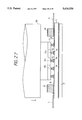
- FIG. 7 shows a perspective view similar to FIG. 6, but with a cap attached.
- FIG. 8 shows a flow chart of the fabrication process of the semiconductor integrated circuit device according to the present invention.
- FIG. 9 shows a sectional view of a semiconductor integrated circuit device according to another aspect of the present invention.
- FIG. 10 shows a sectional view of a semiconductor integrated circuit device according to another aspect of the present invention.
- FIG. 11 shows a perspective view of a cap and a printed wiring substrate for illustrating the fabrication method of the semiconductor integrated circuit device according to another aspect of the present invention.
- FIG. 12 shows a perspective view of a cap and a printed circuit substrate for illustrating the fabrication method of the semiconductor integrated circuit device according to another aspect of the present invention.
- FIG. 13 shows a perspective view similar to FIG. 12, but with the cap attached.
- FIG. 14 shows a flow chart of the fabrication process of the semiconductor integrated circuit device according to another aspect of the present invention.
- FIG. 15 shows a perspective view of a cap and a printed circuit substrate for illustrating the fabrication method of the semiconductor integrated circuit device according to another aspect of the present invention.
- FIG. 16 shows a perspective views of a cap and a printed circuit substrate for illustrating the fabrication method of the semiconductor integrated circuit device according to another aspect of the present invention.
- FIG. 17 shows a perspective view of a cap and a printed circuit substrate for illustrating the fabrication method of the semiconductor integrated circuit device according to another aspect of the present invention.
- FIG. 18 is a sectional view of a semiconductor integrated circuit device according to another aspect of the present invention.
- FIG. 19 is a sectional view showing a metal ball with an anchor embedded into a metal land.
- FIG. 20 is a perspective view of a semiconductor chip with electrode pads formed on an element forming surface
- FIGS. 21(a)-(d) are schematic diagrams showing a method of forming a metal ball on an electrode pad of a semiconductor chip
- FIG. 21(e) is a diagram showing outer dimension of a metal ball.
- FIG. 22 is a perspective view of a semiconductor chip with metal balls formed on electrode pads.
- FIG. 23 is a perspective view of a wiring substrate with electrodes formed on a main surface.
- FIG. 24 is a perspective view of a wiring substrate with metal balls formed on electrodes according to another aspect of the present invention.
- FIG. 25 is a schematic diagram showing a process of flattening metal balls according to the present invention.
- FIG. 26 is a perspective view of a wiring substrate with metal lands formed on electrodes according to another aspect of the present invention.
- FIG. 27 is a schematic diagram showing a method of thermo-compression bonding of metal balls of a semiconductor chip and metal lands of a wiring substrate according to the present invention.
- FIGS. 28(a)-(c) are schematic diagrams showing a method of positioning metal balls of a semiconductor chip and metal lands of a wiring substrate according to the present invention.
- FIG. 29 is a schematic diagram showing the state in which joint failure is produced between metal balls of a semiconductor chip and metal lands of a wiring substrate.
- FIG. 30 is a schematic diagram showing a flattening method of metal balls.
- FIG. 31 is a schematic diagram showing the state in which joint failure is produced between metal balls of a semiconductor chip and metal lands of a wiring substrate.
- FIG. 32 is a schematic diagram showing a method of thermo-compression bonding of metal balls of a semiconductor chip and metal lands of a wiring substrate.
- FIG. 33 is a schematic diagram showing an example of a method of flattening metal balls.
- FIG. 34 is a schematic diagram showing an example of a method of thermo-compression bonding of metal balls of a semiconductor chip and metal lands of a wiring substrate.
- FIG. 35 is a schematic diagram showing an example of a method of thermo-compression bonding of metal balls of a semiconductor chip and metal lands of a wiring substrate.
- FIG. 36 is a schematic diagram showing another example of a flattening method of metal balls.
- FIG. 37 is a schematic diagram showing another example of a method of thermo-compression bonding of metal balls of a semiconductor chip and metal lands of a wiring substrate.
- FIG. 38 is a perspective view of a wiring substrate with a semiconductor chip mounted thereto.
- FIG. 39 is a flow chart showing manufacturing process of a semiconductor integrated circuit device according to another aspect of the present invention.
- FIG. 40 is an enlarged view showing another example of metal balls formed on electrode pads of a semiconductor chip according to the present invention.
- FIG. 41 is a schematic diagram showing a method of flattening tips of anchors of metal balls.
- FIG. 42 is a sectional view showing the state in which the anchor of a metal ball is embedded into a metal land.
- FIG. 43 is a flow chart showing manufacturing process of a semiconductor integrated circuit device according to another aspect of the present invention.
- FIG. 44 is a schematic diagram showing a method of connecting metal balls of a semiconductor chip and electrodes of a wiring substrate according to another aspect of the present invention.
- FIG. 45 is a sectional view showing the state in which the anchor of a metal ball is embedded into an electrode.
- the semiconductor integrated circuit device of this embodiment has a package structure fabricated by sealing a semiconductor chip 10 mounted on a wiring substrate 1 with a cap 18.
- the semiconductor chip 10 is made of a compound semiconductor such as GaAs, on whose element forming surface a semiconductor integrated circuit operated on a radio frequency above 10 GHz and a plurality of electrode pads are formed.
- the printed wiring board 1 is made of ceramic such as alumina or aluminum nitride, on whose surface a plurality of surface wires 3 and a plurality of wiring 1 and electrodes 4 are formed and in which the GND wiring 5a and the power source wiring 5b are formed.
- the surface wiring 3, wiring lands 4, GND wiring 5a, and power source wiring 5b are made of thick films of a refractory metal such as W formed by a screen printing method.
- the surfaces of the surface wiring 3 and wiring lands 4 are plated with Ni and Au in the order from the bottom.
- the surface wirings 3 are wirings for input/output signals, GND, and power source, one end of each of wirings is connected to one of the wiring lands 4.
- the wiring for GND is electrically connected to the GND wiring 5a through a through-hole 2 and the wiring for power source is electrically connected to the power source wiring 5b through the through-holes 2.
- Leads 9 constituting external terminals of the package are formed on the marginal part of the printed wiring board 1.
- the leads 9 are made of a metal such as 42-alloy or copper and bonded to the surface wiring 3 through a lead brazing material 8.
- a GND metallize 5c electrically connected to the GND wiring 5a through a through-hole 2 is formed at the entire back of the printed wiring board 1.
- the GND metallize 5c is of a thick film of a refractory metal such as W plated with Ni and Au.
- a metallic base 17 having almost the same external dimensions as those of the printed wiring board 1 is bonded to the GND metallize 5c through a brazing filler metal 16 for bonding the metallic base.
- the metallic base 17 is made of, for example, W/Cu alloy containing 10% Cu, which is for the stabilization of the GND potential and reinforcement of the package and the heatsink.
- Au lands 14 whose surfaces are flattened by a method which will be mentioned later are bonded to the wiring electrodes or lands 4 formed on the printed wiring board 1.
- Au balls 12 having a diameter smaller than that of the Au lands 14 are bonded to the electrode pads 11 on the element forming surface of the semiconductor chip 10.
- the wiring lands 4 of the printed wiring board 1 is electrically connected to the electrode pads 11 of the semiconductor chip 10 by bonding the Au lands 14 to the Au balls 12 by a thermo-compression bonding which will be mentioned later.
- a square dam frame 6 for sealing is formed around the semiconductor chip 10 on the wiring board 1.
- the dam frame 6 is made of ceramic such as alumina or aluminum nitride.
- the cap 18 is bonded to the surface of the frame 6 through a sealing metallize 7 and brazing filler metal 15 for sealing.
- the sealing dam frame 6 forms a cavity in which the semiconductor chip 10 is mounted.
- the sealing metallize 7 is of a thick film of a refractory metal such as W plated with, for example, Ni and Au and the brazing filler metal 15 for sealing is made of, for example, Au--Sn alloy containing approx. 20% Sn or hard solder.
- the cap 18 is of a metallic plate of, for example, 42-alloy plated with Au.
- a printed wiring board 1 and a semiconductor chip 10 as shown in FIG. 2 are prepared.
- the surface wiring 3 and wiring land 4 of thick films of a refractory metal such as W plated with Ni and Au are formed on the surface of the printed wiring board 1 by a known screen printing method.
- the leads 9 are bonded to the surface wiring 3 on a peripheral area of the printed wiring board 1.
- the sealing dam frame 6 is formed around the chip mounting area on the printed wiring board 1.
- the sealing metallize 7 is formed on the surface of the sealing dam frame 6.
- the metallic base 17 is bonded to the back of the printed wiring board 1.
- the semiconductor chip 10 is made of a compound semiconductor such as GaAs, on which a semiconductor integrated circuit operated on radio frequencies is formed.
- a semiconductor integrated circuit operated on radio frequencies is formed on the element forming surface of the chip 10.
- electrode pads 11 are formed by boring holes in the surface protection film.
- the electrode pads 11 are made of Au similarly to the integrated circuit wirings.
- Au balls 12 are bonded to the electrode pads 11 of the semiconductor chip 10 by a known ball-bonding method using heat or ultrasonic energy or both.
- the Au balls 12 have, for example, a diameter of approx. 120 ⁇ m and a height of approx. 80 ⁇ m.
- the Au balls 12 are bonded to the electrode pads 11 of the semiconductor chip 10 by a ball-bonding method. Therefore, expensive vacuum-deposition equipment and complex lift-off process required to form CCB bumps and BLM layers are unnecessary according to the present invention.
- Au balls 13 are bonded to the wiring lands 4 of the printed wiring board 1 by the above ball-bonding method.
- the diameter and height of the Au balls 13 may be almost the same as those of the Au balls 12.
- the diameter and height of the Au balls 12 and 13 can be adjusted by changing the diameter of an Au wire used.
- the coordinates are used which are made by mirror-inverting the bonding coordinates used to bond the Au balls 12 to the electrode pads 11 of the semiconductor chip 10.
- the Au lands 14 are formed by pressing and flattening the Au balls 13 bonded to the wiring lands 4 of the printed wiring board 1.
- Au lands 14 having a diameter of approx. 180 ⁇ m and a height of approx. 40 ⁇ m can be formed by pressing and flattening the Au balls 13 having a diameter of approx. 120 ⁇ m and a height of approx. 80 ⁇ m by applying a pressure of approx. 100 gf per ball.
- a flattening jig 19 shown in FIG. 5, for example is used. Because the bottom of the flattening jig 19 is accurately flatted, all Au balls 13 on the printed wiring board 1 are simultaneously flattened by pressing the flat surface of the jig against the Au balls 13 from the top. In this case, flattening is performed under a less pressure and in a shorter time by heating the bottom of the flattening jig 19 up to approx. 400° C.
- the Au lands 14 having a larger diameter are formed by pressing and flattening the Au balls 13. Therefore, the wiring lands 4 and the Au lands 14 on the wiring lands 4 contact each other at a larger area even if the contact area between the wiring land 4 and the Au balls 13 bonded to the wiring lands 4 is small because the positions of the wire lands 4 is shifted from the designed coordinates due to the misregistration and bleeding in printing and the shrinkage tolerance of ceramic in baking.
- the Au balls 12 of the semiconductor chip 10 are aligned with the corresponding Au lands 14 on the printed wiring board 1 to bond the Au ball 12 with the Au land 14 by thermo-compression bonding.
- All Au balls 12 are simultaneously bonded to all Au lands 14 by heating the semiconductor chip 10 and printed wiring board 1 up to approx. ****300C and pressing the tool (not illustrated) against the back of the semiconductor chip 10 from the top.
- the pressure applied to the semiconductor chip 10 is, for example, approx. 100 gf for each Au ball 12.
- the Au balls 12 of the semiconductor chip 10 are bonded to the Au lands 14 on the printed wiring board 1 by thermo-compression bonding. Therefore, unlike the conventional CCB method, it is unnecessary to form solder resist and inner layer wirings for the prevention of solder flow and for control of CCB bump shape on the surface wirings 3 of the printed wiring substrate 1.
- FIG. 7 shows a flow chart of the fabrication process described above.
- This embodiment 1 of the above structure has the following advantages:
- the characteristic impedances (z 0 ) of the surface wirings 3 can be easily adjusted by trimming the surface wiring 3 using a laser beam or the like and the performance of a semiconductor integrated circuit device operated on a radio frequency can be improved.
- the thermal resistance of Au is approx. 1/13 the thermal resistance of, for example, Pb/Sn alloy solder containing 5% Sn, it is possible to quickly dissipate the heat produced by the semiconductor chip 10 to the printed wiring substrate 1 through the Au balls 12 and Au lands 14 and thus, the heat dissipation design of a package can be enhanced.
- the semiconductor integrated circuit device of this embodiment is fabricated by bonding Au balls 12b to the electrode pads 11 of the semiconductor chip 10 by a known ball-bonding method using heat or ultrasonic energy or both, similar to the device shown in FIG. 1.
- the embodiment shown in FIG. 9 has second set of Au balls 12a bonded to the Au balls 12b. Both the Au balls 12a and 12b have the diameter of approx. 120 ⁇ m and the height of approx. 80 ⁇ m.
- the diameter in the vertical direction of Au balls is substantially larger because the Au balls 12a and 12b are multistage-bonded to the electrode pads 11 of the semiconductor chip 10. Therefore, even though the variation of height of the wire lands 4 may exists due to the surface warpage and waviness of the printed circuit substrate 1 and the variation of the film thickness of the wiring lands 4 being large such that it cannot be absorbed only by the deformation of the Au balls 13, the height variation can be absorbed by the deformation of the Au balls 12a and 12b.
- thermo-compressing bonding it is possible to decrease the damage done to the semiconductor chip 10 during thermo-compressing bonding because the pressure applied to the back of the semiconductor chip 10 is absorbed by the deformation of the Au balls 12a and 12b when bonding the Au balls 12a to the Au lands 14 by thermo-compressing bonding.
- FIG. 10 shows a semiconductor integrated circuit device similar to the one shown in FIG. 1.
- a heat conductive media of Au ribbons 22 is provided in the space between the back of a semiconductor chip 10 mounted on a printed circuit board 1 and the bottom of a cap 18 to cool the semiconductor chip 10 by conducting heat through the cap.
- Both ends of the Au ribbons 22 are bonded to a heat conductive medium forming metallize 21 provided on the bottom of the cap 18, and the central portions of them contact the back of the semiconductor chip 10.
- the cap 18 is of a metallic plate, for example, a Cu thin plate which is easily bent.
- the heat conductive media forming metallize 21 is formed on the heat conductive media forming area of the cap 18 and the sealing metallize 20 is formed on a marginal part of the cap.
- the heat conductive media forming metallize 21 and the sealing metallize 20 are of thick films of a refractory metal such as W plated with Ni and Au.
- the Au ribbons 22 are bonded to the heat transfer medium forming metallize 21 of the cap 18 by a known ribbon bonding method using heat or ultrasonic energy or both.
- the Au ribbons are made by bonding, for example, an Au tape having a thickness of approx. 20 ⁇ m and a width of approx. 300 ⁇ m in the form of a loop, and the height of the loop is approx. 300 to 1,000 ⁇ m.
- the sealing metallize 7 on the sealing dam frame 6 is bonded to the sealing metallize 20 on the marginal part of the cap 18 by the brazing filler metal 15 for sealing.
- the cap 18 is a metallic plate such as a Cu thin plate which is easily bent, it is deformed toward the inside of the cavity due to the atmospheric pressure after the bonding by the brazing filler metal 15 and the package is cooled and thereby, the inside of the cavity comes to a negative pressure. Therefore, it is possible to securely contact the Au ribbons 22 to the back of the semiconductor chip 10.
- the embodiment 3 of the above structure have the following advantages.
- the above heat dissipating structure in which the semiconductor chip and the cap are joined by solder has a problem in the reliability of connection between the semiconductor chip and printed wiring board because the stress produced due to the difference of thermal expansion coefficient between the printed circuit board, cap, solder, and semiconductor chip is easily applied to the CCB bumps.
- the embodiment 3 in which the easily deformable Au ribbons 22 is provided in the space between the back of the semiconductor chip 10 and the bottom of the cap 18 has the structure in which the stress produced due to the difference of thermal expansion coefficient between the printed circuit board 1, cap 18, and semiconductor chip 10 is absorbed by the deformation of the Au ribbons 22.
- the semiconductor integrated circuit device of the embodiment 4 uses Au wires 23 instead of the Au ribbons 22 as heat conductive media.
- the Au wires 23 are bonded to the heat conductive media forming metallize 21 of the cap 18 by a known wire bonding method using heat or ultrasonic energy or both. Because this embodiment can allow the heat produced by the semiconductor chip 10 to escape not only from the printed wiring board 1 but from the back of the semiconductor chip 10 through the Au wires 23 to the cap 18, the thermal resistance of the semiconductor chip 10 can be decreased similarly to the embodiment shown in FIG. 10 even if a large amount of heat is produced by the semiconductor chip 10.
- the semiconductor integrated circuit device uses Au balls 24 as heat conductive media instead of the ribbons and wires.
- the Au balls 24 are bonded to the heat transfer medium forming metallize 21 of the cap 18 by a known ball bonding method using heating or ultrasonic energy or both similarly to the case when bonding the Au balls 12a to the electrode pads 11 of the semiconductor chip 10.
- This embodiment allows the heat produced by the semiconductor chip 10 not only from the printed wiring board 1 but from the back of the semiconductor chip 10. Therefore, it is possible to decrease the thermal resistance of the semiconductor chip 10 similarly to the embodiments that use wires and ribbons even if a large amount of heat is produced by the semiconductor chip 10.
- FIG. 18 shows a semiconductor device which is substantially similar to the embodiment shown in FIG. 1. However, FIG. 18 shown an embodiment where two Au lands 14 are overlaid and joined onto the electrode 4. On the other hand, an pair of Au ball 30 having smaller diameter than that of the Au land 14 are provided on each of the electrode pads 11 of the semiconductor chip 10. It is to be noted that one or more than two lands 14 and balls can also be overlaid as desired.
- the wiring substrate 1 and the semiconductor chip 10 are electrically connected by the thermo compression bonding of the Au land 14 and the Au ball 30.
- the Au ball 30 of the semiconductor chip 10 is provided with an anchor 32 having a sharpened tip, where the anchor 32 is embedded into the Au land 14 on the electrode 4 of the wiring substrate 1.
- FIGS. 20-39 A manufacturing method of a semiconductor integrated circuit device having the above-mentioned constitution will be described using FIGS. 20-39.
- a semiconductor chip 10 having electrode pads 11 being many terminals formed on an element forming surface is prepared.
- the electrode pad 11 is made of gold (Au).
- an Au ball 30 being a first metal ball is formed on the electrode pad 11 by a well-known ball bonding method described above. That is, the semiconductor chip 10 is positioned on a stage of a wire bonding apparatus (not shown), and as shown in FIG. 21(a), a gold ball 30 is formed at a tip of an Au wire 103 using a torch 102. The gold ball 30 is joined onto the electrode pad 11 as shown in FIG. 21(b). Next, only a capillary 101 is elevated as shown in FIG.
- FIG. 21(c) An example of outer dimension of the Au ball is shown in FIG. 21(e), the dimension unit being ⁇ m.
- Au balls 30 are formed in sequence on all electrode pads 11, and a semiconductor chip 10 is obtained as shown in FIG. 22.
- a wiring substrate 1 with a number of electrodes 4 formed thereon is prepared, and a pair of Au balls 13 (second metal balls) are overlaid and formed on each electrode 4 by the above-mentioned ball bonding method, thereby obtaining a wiring substrate 1 as shown in FIG. 24.
- Outer dimension of the Au ball 13 is the same as that of the Au ball 30 formed on the electrode pad 11 of the semiconductor chip 10.
- an anchor 32 is formed also on the upper end portion of the Au ball 13, but has not been represented in the drawings for convenience.
- the wiring substrate 1 is put on a horizontal stage 114 as shown in FIG. 25 and compression bonding of a tool 110 is carried out to the Au balls 13 from upper side and the upper surface is flattened, that is, height of the top of the second metal balls 13 is equalized, thereby Au lands 14 (metal electrodes) as shown in FIG. 26 are formed on the electrodes 4 of the wiring substrate 1.
- the load applied to the Au balls 13 is about 300 gf per one Au ball 13.
- the tool 110 has the bottom surface flattened at high accuracy. Further, the tool 110 is heated to about 4000C, thereby the load applied to the Au ball 13 can be decreased.
- the semiconductor chip 10 with the Au balls 30 formed on the electrode pads 11 are attached to the bottom surface of the tool 111 for thermo-compression bonding, and the Au balls 30 of the semiconductor chip 10 and the Au lands 14 of the wiring substrate 1 corresponding to the Au balls 30 are overlaid each other and joined by thermo-compression bonding.
- the Au balls 30 and the Au lands 14 are electrically connected by embedding the anchors 32 into the Au lands 14.
- a pattern of the Au balls 30 is recognized using a half mirror 112 and a picture analyzing apparatus 113 as shown in FIG. 28(a).
- the half mirror 112 is rotated by 90° and a pattern of the Au land 14 of the wiring substrate 1 is recognized as shown in FIG. 28(b).
- the semiconductor chip 10 is moved or rotated longitudinally and laterally and the image of pattern of the Au balls 30 and the Au lands 14 are overlaid upon each other, and then the tool 111 is lowered onto the wiring substrate 1 as shown in FIG. 28(c), and all Au balls 30 and all Au lands 14 are subjected to thermo-compression bonding at the same time.
- the anchors 32 of the Au balls 30 are embedded into the Au lands 14.
- the Au balls 30 are heated at a lower temperature (about 250° C.) than the recrystallization temperature of Au (about 300° C.), and the Au lands 14 of the wiring substrate 1 is heated at a higher temperature (about 350° C.) than the recrystallization temperature of Au. Since the Au land 14 of the wiring substrate 1 becomes softer than the Au ball 30 of the semiconductor chip 10, the anchor 32 of the Au ball 30 can be securely embedded into the Au land 14 with a little load.
- the anchors 32 are provided at the upper end position of the Au balls 30, since the anchors 32 bite into the Au lands 14, slippage of the Au balls 30 is prevented and the Au balls 30 and the Au lands 14 can be securely joined.
- thermo compression bonding is carried out preferably using the stage 114 and the tool 110 (refer to FIG. 25) used when the Au ball 13 on the electrode 4 of the wiring substrate 1 is flattened. That is, when the Au balls 13 are flattened, the upper surface of the stage 114 must be in parallel to the bottom surface of the tool 110, but they are not completely in parallel because of limitation of the machining. Consequently, such a misalignment can cause uneven height Au lands, with an incline proportional to the relative inclination between the bottom surface of the tool 110 and the upper surface of the stage 114. Consequently, as shown in FIG.
- thermo-compression bonding is carried out using a tool 111 and a stage 115 other than the tool 110 and the stage 114 as above described, since the relative inclination between the bottom surface of the tool 11 and the upper surface of the stage 115 is different from the relative inclination between the bottom surface of the tool 110 and the upper surface of the stage 114, when the Au ball 13 of the wiring substrate 1 and the Au ball 30 of the semiconductor chip 10 are overlaid each other, the tips of the Au balls 30 and the upper surface of the Au lands 14 do not become parallel. As a result, the thermo compression bonding of all Au balls 30 and all Au lands 14 cannot be carried out uniformly at the same load, and unsymmetrical partial floatation is produced between the Au balls 30 and Au lands 14.
- thermo-compression bonding of the Au balls 30 and the Au lands 14 is carried out using the stage 114 and the tool 110 used in flattening the Au balls 13 of the wiring substrate 1, since the relative inclination between the upper surface of the stage 114 and the bottom surface of the tool 110 is not varied during flattening the Au balls 13 and during the thermo-compression bonding of the Au balls 30 and the Au lands 14, as shown in FIG. 32, the tips of the Au balls 30 of the semiconductor chip 10 held at the bottom surface of the tool 110 and the upper surface of the Au lands 14 of the wiring substrate 1 put on the stage 114 become completely parallel, and the thermo compression bonding of all balls 30 and all lands 14 can be carried out uniformly at the same load.
- the flattening and the thermo-compression bonding are carried out in following manner.
- the Au lands 14 are formed with uneven height proportional to relative inclination between the bottom surface of the tool 110 and the upper surface of the tool 110.
- the Au balls 30 of the semiconductor chip 10 and the Au land 14s of the wiring substrate 1 corresponding to the Au balls 30 are overlaid upon each other. Then the load applied to the rear surface of the semiconductor chip 10 is decreased and the joining between the Au balls 30 and the Au lands 14 is made incomplete. In this case, even if the joining between both is incomplete, since the anchors 32 provided at the Au ball 30 bites into the Au balls 30 weakly, positions of both are not deviated.
- the flattening of the Au balls 13 and thermo-compression bonding of the Au balls 30 to the Au lands 14 may be carried out also in following method.
- a dummy chip 117 having the same flatness as that of a semiconductor chip 10 is attached to the bottom surface of a tool 110, and the bottom surface of the dummy chip 132 is bonded in compression bonding to an Au balls 13 of a wiring substrate 1 put on a stage 114 to form Au lands 14.
- a thin film of high hardness such as diamond is coated at the bottom surface of the dummy chip 117, breaking of the dummy chip 117 or abrasion of the bottom surface can be prevented.
- the dummy chip 117 is detached from the bottom surface of the tool 110 and the semiconductor chip 10 is attached, and the Au balls 30 of the semiconductor chip 10 and the Au land 14 of the wiring substrate 1 are overlaid and joined by thermo-compression bonding.
- the flattening and the thermo-compression bonding are carried out using the same stage 114 and the tool 110, all Au balls 30 and all Au lands 14 can be joined at the uniform load.
- the surface of the semiconductor chip 10 usually has the flatness much higher than that of the bottom surface of the tool 110, other chip having nearly the same flatness as that of the semiconductor chip 10, that is, the dummy chip 117 is bonded in compression bonding to the Au balls 13 and the Au lands 14 is formed, thereby dispersion of height of the Au land 14 caused by roughness of the bottom surface of the tool 110 is reduced to a negligible degree, and the Au balls 30 and the Au lands 14 can be overlaid and joined with high accuracy.
- FIG. 38 shows a wiring substrate 1 on which a semiconductor chip 10 is mounted according to the above mentioned method. Then, then a cap 18 is joined to an upper surface of a dam frame 6 of the wiring substrate 1 as previously described.
- FIG. 39 is a flow chart of a manufacturing process described above.
- the Au balls 30 having anchors 32 are formed on an electrode pad 11 of a semiconductor chip 10, and then tips of the anchors 32 are flattened slightly to equalize the height thereof. Consequently, since height of not only the Au lands 14 of the wiring substrate 1 but also the Au balls 30 of the semiconductor chip 10 can be equalized. The Au balls 30 and the Au lands 14 can thus be overlaid and joined with high accuracy.
- FIG. 41 is a flow chart of the manufacturing process described above.
- electrode 4 is constituted by a conductive plastic film.
- the Au-balls 30 and the electrodes 4 are overlaid and the load may be applied to the rear surface of the semiconductor chip 10.
- the electrode 4 is constituted by plastics softer than the Au ball 30, as shown in FIG. 45, the anchors 32 of the Au balls 30 can be easily embedded into the electrode 4 to securely connect the Au balls 30 to the electrodes 4.
- the wiring substrate 1 and the semiconductor chip 10 can be connected easily and securely.
- the electrode 4 of the wiring substrate 1 may be made of a soft material such as conductive rubber.
- Au balls are joined onto the electrode pads of the semiconductor chip, any other metal having malleability and capable of being joined by thermo-compression bonding may be used.
- the Au balls are bonded to electrode pads of a semiconductor chip by a ball bonding method using heat or ultrasonic energy or both.
- a ball bonding method using heat or ultrasonic energy or both.
- the above embodiments described are the case in which a compound semiconductor chip made of, for example, GaAs and having a semiconductor integrated circuit operated on radio frequencies is mounted on a printed circuit board.
- the present invention can be also applied to a case in which a semiconductor chip with many pins or a semiconductor chip producing a large amount of heat is mounted on the printed circuit board.
Abstract
Description
Claims (21)
Priority Applications (1)
| Application Number | Priority Date | Filing Date | Title |
|---|---|---|---|
| US08/367,490 US5616520A (en) | 1992-03-30 | 1994-12-30 | Semiconductor integrated circuit device and fabrication method thereof |
Applications Claiming Priority (7)
| Application Number | Priority Date | Filing Date | Title |
|---|---|---|---|
| JP4071767A JPH05275491A (en) | 1992-03-30 | 1992-03-30 | Manufacture of semiconductor integrated circuit device and the device obtained from the same |
| JP4-71767 | 1992-03-30 | ||
| US3657793A | 1993-03-24 | 1993-03-24 | |
| JP5-116266 | 1993-05-19 | ||
| JP5116266A JPH06333982A (en) | 1993-05-19 | 1993-05-19 | Manufacture of semiconductor integrated circuit device |
| US22659794A | 1994-04-12 | 1994-04-12 | |
| US08/367,490 US5616520A (en) | 1992-03-30 | 1994-12-30 | Semiconductor integrated circuit device and fabrication method thereof |
Related Parent Applications (1)
| Application Number | Title | Priority Date | Filing Date |
|---|---|---|---|
| US22659794A Continuation-In-Part | 1992-03-30 | 1994-04-12 |
Publications (1)
| Publication Number | Publication Date |
|---|---|
| US5616520A true US5616520A (en) | 1997-04-01 |
Family
ID=27465401
Family Applications (1)
| Application Number | Title | Priority Date | Filing Date |
|---|---|---|---|
| US08/367,490 Expired - Lifetime US5616520A (en) | 1992-03-30 | 1994-12-30 | Semiconductor integrated circuit device and fabrication method thereof |
Country Status (1)
| Country | Link |
|---|---|
| US (1) | US5616520A (en) |
Cited By (47)
| Publication number | Priority date | Publication date | Assignee | Title |
|---|---|---|---|---|
| WO1998050949A2 (en) * | 1997-05-07 | 1998-11-12 | Lsi Logic Corporation | Pbga stiffener package and method of manufacturing |
| US6046074A (en) * | 1995-06-05 | 2000-04-04 | International Business Machines Corporation | Hermetic thin film metallized sealband for SCM and MCM-D modules |
| US6121679A (en) * | 1998-03-10 | 2000-09-19 | Luvara; John J. | Structure for printed circuit design |
| US6176417B1 (en) * | 1999-10-15 | 2001-01-23 | Advanced Semiconductor Engineering Inc. | Ball bonding method on a chip |
| US6179198B1 (en) * | 1996-09-18 | 2001-01-30 | Matsushita Electric Industrial Co., Ltd. | Method of soldering bumped work by partially penetrating the oxide film covering the solder bumps |
| US6225206B1 (en) | 1999-05-10 | 2001-05-01 | International Business Machines Corporation | Flip chip C4 extension structure and process |
| US6239497B1 (en) * | 1997-07-23 | 2001-05-29 | Nec Corporation | Substrate for packing semiconductor device and method for packing a semiconductor device in the substrate |
| US6282780B1 (en) * | 1996-02-08 | 2001-09-04 | Matsushita Electric Industrial Co., Ltd. | Bump forming method and its forming apparatus. |
| US6285083B1 (en) * | 1999-03-24 | 2001-09-04 | Shinko Electric Industries Co., Ltd. | Semiconductor device and mounting structure of a semiconductor device |
| US6310303B1 (en) | 1998-03-10 | 2001-10-30 | John J. Luvara | Structure for printed circuit design |
| WO2002009484A2 (en) * | 2000-07-21 | 2002-01-31 | Nanopierce Technologies, Inc. | Electrical component assembly and method of fabrication |
| EP1225631A2 (en) * | 2000-12-22 | 2002-07-24 | Vlt Corporation | Heat dissipation arrangement for electronic components |
| US20030006509A1 (en) * | 2001-07-05 | 2003-01-09 | Takehiro Suzuki | Semiconductor device |
| US20030007334A1 (en) * | 2001-06-28 | 2003-01-09 | Farhad Farassat | Circuit housing |
| US6521478B2 (en) * | 2001-03-20 | 2003-02-18 | Computech International Ventures Limited | Method for manufacturing a low-profile semiconductor device |
| US6696755B2 (en) * | 2002-03-14 | 2004-02-24 | Nec Corporation | Semiconductor device |
| US6720647B2 (en) * | 2000-06-05 | 2004-04-13 | Nec Electronics Corporation | Semiconductor device and method of manufacturing the same |
| US20040087128A1 (en) * | 2000-10-24 | 2004-05-06 | Neuhaus Herbert J | Method and materials for printing particle-enhanced electrical contacts |
| US20040124539A1 (en) * | 2002-12-31 | 2004-07-01 | Advanced Semiconductor Engineering, Inc. | Multi-chip stack flip-chip package |
| US6853087B2 (en) | 2000-09-19 | 2005-02-08 | Nanopierce Technologies, Inc. | Component and antennae assembly in radio frequency identification devices |
| US20050082580A1 (en) * | 2002-12-13 | 2005-04-21 | Chih-Pin Hung | Structure of wafer level package with area bump |
| US20050161814A1 (en) * | 2002-12-27 | 2005-07-28 | Fujitsu Limited | Method for forming bumps, semiconductor device and method for manufacturing same, substrate processing apparatus, and semiconductor manufacturing apparatus |
| US20060071325A1 (en) * | 2004-10-05 | 2006-04-06 | Yasuhiko Tanaka | Semiconductor device and electronic apparatus |
| US20060144907A1 (en) * | 2004-12-30 | 2006-07-06 | Sohichi Kadoguchi | Wire bonds having pressure-absorbing balls |
| US20060175701A1 (en) * | 2005-02-04 | 2006-08-10 | Harald Gross | Dissociated fabrication of packages and chips of integrated circuits |
| US20060278682A1 (en) * | 2005-06-09 | 2006-12-14 | Texas Instruments Incorporated | Bond capillary design for ribbon wire bonding |
| WO2007001976A2 (en) * | 2005-06-20 | 2007-01-04 | R828 Llc | Semiconductor structure with rf element |
| US20070108627A1 (en) * | 2005-11-15 | 2007-05-17 | Matsushita Electric Industrial Co., Ltd. | Semiconductor device and method for manufacturing the same |
| US20080291655A1 (en) * | 2007-05-23 | 2008-11-27 | Samsung Electronics Co. Ltd. | Wiring substrate, semiconductor device package including the wiring substrate and methods of fabricating the same |
| US20090289350A1 (en) * | 2005-09-29 | 2009-11-26 | Nec Corporation | Semiconductor package, substrate, electronic device using such semiconductor package or substrate, and method for correcting warping of semiconductor package |
| US20100013095A1 (en) * | 2005-08-22 | 2010-01-21 | Motoharu Hada | Semiconductor device, production method for the same, and substrate |
| US20100039779A1 (en) * | 2008-08-15 | 2010-02-18 | Siemens Power Generation, Inc. | Wireless Telemetry Electronic Circuit Board for High Temperature Environments |
| US20110193097A1 (en) * | 2010-02-09 | 2011-08-11 | Tracy Autry | Silicon carbide semiconductor |
| US20110193098A1 (en) * | 2010-02-09 | 2011-08-11 | Tracy Autry | High voltage high package pressure semiconductor package |
| US20110204497A1 (en) * | 2010-02-24 | 2011-08-25 | Renesas Electronics Corporation | Semiconductor integrated circuit and method for manufacturing the same |
| US20140217456A1 (en) * | 2013-02-05 | 2014-08-07 | Samsung Electronics Co., Ltd. | Electronic apparatus |
| USD792410S1 (en) * | 2013-03-13 | 2017-07-18 | Nagrastar Llc | Smart card interface |
| EP3255659A4 (en) * | 2015-03-06 | 2018-04-11 | Mitsubishi Heavy Industries, Ltd. | Bonding method and bonded body |
| USD840404S1 (en) * | 2013-03-13 | 2019-02-12 | Nagrastar, Llc | Smart card interface |
| US20190088567A1 (en) * | 2017-09-21 | 2019-03-21 | Sheng Hsieng Chang | Inorganic Packaging Module Having a Chip Encapsulated Therein |
| USD864968S1 (en) | 2015-04-30 | 2019-10-29 | Echostar Technologies L.L.C. | Smart card interface |
| US11178786B2 (en) * | 2014-12-26 | 2021-11-16 | Hitachi Metals, Ltd. | Method for manufacturing hermetic sealing lid member |
| US20220077656A1 (en) * | 2020-09-08 | 2022-03-10 | Hewlett Packard Enterprise Development Lp | Thermal management for hybrid lasers |
| US11373979B2 (en) * | 2003-08-29 | 2022-06-28 | Micron Technology, Inc. | Stacked microfeature devices and associated methods |
| US11705387B2 (en) | 2020-09-02 | 2023-07-18 | Infineon Technologies Ag | Multi-layer interconnection ribbon |
| US11716816B2 (en) | 2003-09-18 | 2023-08-01 | Imberatek, Llc | Method for manufacturing an electronic module and electronic module |
| US11792941B2 (en) | 2005-06-16 | 2023-10-17 | Imberatek, Llc | Circuit board structure and method for manufacturing a circuit board structure |
Citations (14)
| Publication number | Priority date | Publication date | Assignee | Title |
|---|---|---|---|---|
| US4372037A (en) * | 1975-03-03 | 1983-02-08 | Hughes Aircraft Company | Large area hybrid microcircuit assembly |
| US4604644A (en) * | 1985-01-28 | 1986-08-05 | International Business Machines Corporation | Solder interconnection structure for joining semiconductor devices to substrates that have improved fatigue life, and process for making |
| US4874721A (en) * | 1985-11-11 | 1989-10-17 | Nec Corporation | Method of manufacturing a multichip package with increased adhesive strength |
| US4874722A (en) * | 1987-04-16 | 1989-10-17 | Texas Instruments Incorporated | Process of packaging a semiconductor device with reduced stress forces |
| US4957882A (en) * | 1988-11-25 | 1990-09-18 | Mitsubishi Denki Kabushiki Kaisha | Method for manufacturing semiconductor device |
| US5071787A (en) * | 1989-03-14 | 1991-12-10 | Kabushiki Kaisha Toshiba | Semiconductor device utilizing a face-down bonding and a method for manufacturing the same |
| JPH03283542A (en) * | 1990-03-30 | 1991-12-13 | Tanaka Denshi Kogyo Kk | Bonding of semiconductor chip |
| US5126818A (en) * | 1987-05-26 | 1992-06-30 | Matsushita Electric Works, Ltd. | Semiconductor device |
| US5172851A (en) * | 1990-09-20 | 1992-12-22 | Matsushita Electronics Corporation | Method of forming a bump electrode and manufacturing a resin-encapsulated semiconductor device |
| US5186381A (en) * | 1991-04-16 | 1993-02-16 | Samsung Electronics, Co., Ltd. | Semiconductor chip bonding process |
| US5201451A (en) * | 1987-03-11 | 1993-04-13 | International Business Machines Corp. | Method and apparatus for mounting a flexible film semiconductor chip carrier on a circuitized substrate |
| JPH05144872A (en) * | 1991-11-21 | 1993-06-11 | Tanaka Denshi Kogyo Kk | Joining method of bump electrode |
| US5219794A (en) * | 1991-03-14 | 1993-06-15 | Hitachi, Ltd. | Semiconductor integrated circuit device and method of fabricating same |
| US5249450A (en) * | 1992-06-15 | 1993-10-05 | Micron Technology, Inc. | Probehead for ultrasonic forging |
-
1994
- 1994-12-30 US US08/367,490 patent/US5616520A/en not_active Expired - Lifetime
Patent Citations (14)
| Publication number | Priority date | Publication date | Assignee | Title |
|---|---|---|---|---|
| US4372037A (en) * | 1975-03-03 | 1983-02-08 | Hughes Aircraft Company | Large area hybrid microcircuit assembly |
| US4604644A (en) * | 1985-01-28 | 1986-08-05 | International Business Machines Corporation | Solder interconnection structure for joining semiconductor devices to substrates that have improved fatigue life, and process for making |
| US4874721A (en) * | 1985-11-11 | 1989-10-17 | Nec Corporation | Method of manufacturing a multichip package with increased adhesive strength |
| US5201451A (en) * | 1987-03-11 | 1993-04-13 | International Business Machines Corp. | Method and apparatus for mounting a flexible film semiconductor chip carrier on a circuitized substrate |
| US4874722A (en) * | 1987-04-16 | 1989-10-17 | Texas Instruments Incorporated | Process of packaging a semiconductor device with reduced stress forces |
| US5126818A (en) * | 1987-05-26 | 1992-06-30 | Matsushita Electric Works, Ltd. | Semiconductor device |
| US4957882A (en) * | 1988-11-25 | 1990-09-18 | Mitsubishi Denki Kabushiki Kaisha | Method for manufacturing semiconductor device |
| US5071787A (en) * | 1989-03-14 | 1991-12-10 | Kabushiki Kaisha Toshiba | Semiconductor device utilizing a face-down bonding and a method for manufacturing the same |
| JPH03283542A (en) * | 1990-03-30 | 1991-12-13 | Tanaka Denshi Kogyo Kk | Bonding of semiconductor chip |
| US5172851A (en) * | 1990-09-20 | 1992-12-22 | Matsushita Electronics Corporation | Method of forming a bump electrode and manufacturing a resin-encapsulated semiconductor device |
| US5219794A (en) * | 1991-03-14 | 1993-06-15 | Hitachi, Ltd. | Semiconductor integrated circuit device and method of fabricating same |
| US5186381A (en) * | 1991-04-16 | 1993-02-16 | Samsung Electronics, Co., Ltd. | Semiconductor chip bonding process |
| JPH05144872A (en) * | 1991-11-21 | 1993-06-11 | Tanaka Denshi Kogyo Kk | Joining method of bump electrode |
| US5249450A (en) * | 1992-06-15 | 1993-10-05 | Micron Technology, Inc. | Probehead for ultrasonic forging |
Cited By (81)
| Publication number | Priority date | Publication date | Assignee | Title |
|---|---|---|---|---|
| US6046074A (en) * | 1995-06-05 | 2000-04-04 | International Business Machines Corporation | Hermetic thin film metallized sealband for SCM and MCM-D modules |
| US6282780B1 (en) * | 1996-02-08 | 2001-09-04 | Matsushita Electric Industrial Co., Ltd. | Bump forming method and its forming apparatus. |
| US6179198B1 (en) * | 1996-09-18 | 2001-01-30 | Matsushita Electric Industrial Co., Ltd. | Method of soldering bumped work by partially penetrating the oxide film covering the solder bumps |
| WO1998050949A3 (en) * | 1997-05-07 | 1999-02-04 | Lsi Logic Corp | Pbga stiffener package and method of manufacturing |
| US5972738A (en) * | 1997-05-07 | 1999-10-26 | Lsi Logic Corporation | PBGA stiffener package |
| WO1998050949A2 (en) * | 1997-05-07 | 1998-11-12 | Lsi Logic Corporation | Pbga stiffener package and method of manufacturing |
| US6239497B1 (en) * | 1997-07-23 | 2001-05-29 | Nec Corporation | Substrate for packing semiconductor device and method for packing a semiconductor device in the substrate |
| US6121679A (en) * | 1998-03-10 | 2000-09-19 | Luvara; John J. | Structure for printed circuit design |
| US6310303B1 (en) | 1998-03-10 | 2001-10-30 | John J. Luvara | Structure for printed circuit design |
| US6285083B1 (en) * | 1999-03-24 | 2001-09-04 | Shinko Electric Industries Co., Ltd. | Semiconductor device and mounting structure of a semiconductor device |
| US6955982B2 (en) | 1999-05-10 | 2005-10-18 | International Business Machines Corporation | Flip chip C4 extension structure and process |
| US6225206B1 (en) | 1999-05-10 | 2001-05-01 | International Business Machines Corporation | Flip chip C4 extension structure and process |
| US6756680B2 (en) | 1999-05-10 | 2004-06-29 | International Business Machines Corporation | Flip chip C4 extension structure and process |
| US6664637B2 (en) | 1999-05-10 | 2003-12-16 | International Business Machines Corporation | Flip chip C4 extension structure and process |
| US20040094842A1 (en) * | 1999-05-10 | 2004-05-20 | Jimarez Miguel A. | Flip chip C4 extension structure and process |
| US6176417B1 (en) * | 1999-10-15 | 2001-01-23 | Advanced Semiconductor Engineering Inc. | Ball bonding method on a chip |
| US6720647B2 (en) * | 2000-06-05 | 2004-04-13 | Nec Electronics Corporation | Semiconductor device and method of manufacturing the same |
| WO2002009484A2 (en) * | 2000-07-21 | 2002-01-31 | Nanopierce Technologies, Inc. | Electrical component assembly and method of fabrication |
| WO2002009484A3 (en) * | 2000-07-21 | 2002-06-06 | Nanopierce Technologies Inc | Electrical component assembly and method of fabrication |
| US6853087B2 (en) | 2000-09-19 | 2005-02-08 | Nanopierce Technologies, Inc. | Component and antennae assembly in radio frequency identification devices |
| US20040087128A1 (en) * | 2000-10-24 | 2004-05-06 | Neuhaus Herbert J | Method and materials for printing particle-enhanced electrical contacts |
| EP1225631A2 (en) * | 2000-12-22 | 2002-07-24 | Vlt Corporation | Heat dissipation arrangement for electronic components |
| EP1225631A3 (en) * | 2000-12-22 | 2003-06-04 | Vlt Corporation | Heat dissipation arrangement for electronic components |
| US6521478B2 (en) * | 2001-03-20 | 2003-02-18 | Computech International Ventures Limited | Method for manufacturing a low-profile semiconductor device |
| EP1286393A3 (en) * | 2001-06-28 | 2004-03-03 | F & K Delvotec Bondtechnik GmbH | Circuit housing |
| EP1286393A2 (en) * | 2001-06-28 | 2003-02-26 | F & K Delvotec Bondtechnik GmbH | Circuit housing |
| US20030007334A1 (en) * | 2001-06-28 | 2003-01-09 | Farhad Farassat | Circuit housing |
| US6891730B2 (en) * | 2001-06-28 | 2005-05-10 | F & K Delvotec Bondtechnik Gmbh | Circuit housing |
| US7193328B2 (en) * | 2001-07-05 | 2007-03-20 | Sharp Kabushiki Kaisha | Semiconductor device |
| US20030006509A1 (en) * | 2001-07-05 | 2003-01-09 | Takehiro Suzuki | Semiconductor device |
| US6696755B2 (en) * | 2002-03-14 | 2004-02-24 | Nec Corporation | Semiconductor device |
| US20050082580A1 (en) * | 2002-12-13 | 2005-04-21 | Chih-Pin Hung | Structure of wafer level package with area bump |
| US20090186425A1 (en) * | 2002-12-27 | 2009-07-23 | Fujitsu Limited | Method for forming bumps, semiconductor device and method for manufacturing same, substrate processing apparatus, and semiconductor manufacturing apparatus |
| US20050161814A1 (en) * | 2002-12-27 | 2005-07-28 | Fujitsu Limited | Method for forming bumps, semiconductor device and method for manufacturing same, substrate processing apparatus, and semiconductor manufacturing apparatus |
| US8962470B2 (en) | 2002-12-27 | 2015-02-24 | Fujitsu Limited | Method for forming bumps, semiconductor device and method for manufacturing same, substrate processing apparatus, and semiconductor manufacturing apparatus |
| US20040124539A1 (en) * | 2002-12-31 | 2004-07-01 | Advanced Semiconductor Engineering, Inc. | Multi-chip stack flip-chip package |
| US6861761B2 (en) * | 2002-12-31 | 2005-03-01 | Advanced Semiconductor Engineering Inc. | Multi-chip stack flip-chip package |
| US11887970B2 (en) | 2003-08-29 | 2024-01-30 | Micron Technology, Inc. | Stacked microfeature devices and associated methods |
| US11373979B2 (en) * | 2003-08-29 | 2022-06-28 | Micron Technology, Inc. | Stacked microfeature devices and associated methods |
| US11716816B2 (en) | 2003-09-18 | 2023-08-01 | Imberatek, Llc | Method for manufacturing an electronic module and electronic module |
| US20060071325A1 (en) * | 2004-10-05 | 2006-04-06 | Yasuhiko Tanaka | Semiconductor device and electronic apparatus |
| US20060144907A1 (en) * | 2004-12-30 | 2006-07-06 | Sohichi Kadoguchi | Wire bonds having pressure-absorbing balls |
| US7404513B2 (en) * | 2004-12-30 | 2008-07-29 | Texas Instruments Incorporated | Wire bonds having pressure-absorbing balls |
| US20060175701A1 (en) * | 2005-02-04 | 2006-08-10 | Harald Gross | Dissociated fabrication of packages and chips of integrated circuits |
| US7459376B2 (en) * | 2005-02-04 | 2008-12-02 | Infineon Technologies Ag | Dissociated fabrication of packages and chips of integrated circuits |
| US7216794B2 (en) | 2005-06-09 | 2007-05-15 | Texas Instruments Incorporated | Bond capillary design for ribbon wire bonding |
| US7578422B2 (en) | 2005-06-09 | 2009-08-25 | Texas Instruments Incorporated | Bond capillary design for ribbon wire bonding |
| US20060278682A1 (en) * | 2005-06-09 | 2006-12-14 | Texas Instruments Incorporated | Bond capillary design for ribbon wire bonding |
| US11792941B2 (en) | 2005-06-16 | 2023-10-17 | Imberatek, Llc | Circuit board structure and method for manufacturing a circuit board structure |
| WO2007001976A2 (en) * | 2005-06-20 | 2007-01-04 | R828 Llc | Semiconductor structure with rf element |
| WO2007001976A3 (en) * | 2005-06-20 | 2007-03-08 | R828 Llc | Semiconductor structure with rf element |
| US20100013095A1 (en) * | 2005-08-22 | 2010-01-21 | Motoharu Hada | Semiconductor device, production method for the same, and substrate |
| US7902681B2 (en) * | 2005-08-22 | 2011-03-08 | Rohm Co., Ltd. | Semiconductor device, production method for the same, and substrate |
| US20110115089A1 (en) * | 2005-08-22 | 2011-05-19 | Rohm Co., Ltd. | Semiconductor device, production method for the same, and substrate |
| US8368234B2 (en) | 2005-08-22 | 2013-02-05 | Rohm Co., Ltd. | Semiconductor device, production method for the same, and substrate |
| US20090289350A1 (en) * | 2005-09-29 | 2009-11-26 | Nec Corporation | Semiconductor package, substrate, electronic device using such semiconductor package or substrate, and method for correcting warping of semiconductor package |
| US7629687B2 (en) * | 2005-11-15 | 2009-12-08 | Panasonic Corporation | Semiconductor device and method for manufacturing the same |
| US20070108627A1 (en) * | 2005-11-15 | 2007-05-17 | Matsushita Electric Industrial Co., Ltd. | Semiconductor device and method for manufacturing the same |
| US20080291655A1 (en) * | 2007-05-23 | 2008-11-27 | Samsung Electronics Co. Ltd. | Wiring substrate, semiconductor device package including the wiring substrate and methods of fabricating the same |
| US8266796B2 (en) * | 2007-05-23 | 2012-09-18 | Samsung Electronics Co., Ltd. | Method of fabricating a semiconductor device package |
| US20100039779A1 (en) * | 2008-08-15 | 2010-02-18 | Siemens Power Generation, Inc. | Wireless Telemetry Electronic Circuit Board for High Temperature Environments |
| US8023269B2 (en) * | 2008-08-15 | 2011-09-20 | Siemens Energy, Inc. | Wireless telemetry electronic circuit board for high temperature environments |
| US8587107B2 (en) * | 2010-02-09 | 2013-11-19 | Microsemi Corporation | Silicon carbide semiconductor |
| US8237171B2 (en) * | 2010-02-09 | 2012-08-07 | Microsemi Corporation | High voltage high package pressure semiconductor package |
| US20110193098A1 (en) * | 2010-02-09 | 2011-08-11 | Tracy Autry | High voltage high package pressure semiconductor package |
| US20110193097A1 (en) * | 2010-02-09 | 2011-08-11 | Tracy Autry | Silicon carbide semiconductor |
| US20110204497A1 (en) * | 2010-02-24 | 2011-08-25 | Renesas Electronics Corporation | Semiconductor integrated circuit and method for manufacturing the same |
| US20140217456A1 (en) * | 2013-02-05 | 2014-08-07 | Samsung Electronics Co., Ltd. | Electronic apparatus |
| US9099630B2 (en) * | 2013-02-05 | 2015-08-04 | Samsung Electronics Co., Ltd. | Electronic apparatus |
| USD792411S1 (en) * | 2013-03-13 | 2017-07-18 | Nagrastar Llc | Smart card interface |
| USD949864S1 (en) * | 2013-03-13 | 2022-04-26 | Nagrastar Llc | Smart card interface |
| USD840404S1 (en) * | 2013-03-13 | 2019-02-12 | Nagrastar, Llc | Smart card interface |
| USD792410S1 (en) * | 2013-03-13 | 2017-07-18 | Nagrastar Llc | Smart card interface |
| US11178786B2 (en) * | 2014-12-26 | 2021-11-16 | Hitachi Metals, Ltd. | Method for manufacturing hermetic sealing lid member |
| EP3255659A4 (en) * | 2015-03-06 | 2018-04-11 | Mitsubishi Heavy Industries, Ltd. | Bonding method and bonded body |
| USD864968S1 (en) | 2015-04-30 | 2019-10-29 | Echostar Technologies L.L.C. | Smart card interface |
| US10636718B2 (en) * | 2017-09-21 | 2020-04-28 | Chang Sheng Hsiang Chang | Inorganic packaging module having a chip encapsulated therein |
| US20190088567A1 (en) * | 2017-09-21 | 2019-03-21 | Sheng Hsieng Chang | Inorganic Packaging Module Having a Chip Encapsulated Therein |
| US11705387B2 (en) | 2020-09-02 | 2023-07-18 | Infineon Technologies Ag | Multi-layer interconnection ribbon |
| US20220077656A1 (en) * | 2020-09-08 | 2022-03-10 | Hewlett Packard Enterprise Development Lp | Thermal management for hybrid lasers |
| US11876345B2 (en) * | 2020-09-08 | 2024-01-16 | Hewlett Packard Enterprise Development Lp | Thermal management for hybrid lasers |
Similar Documents
| Publication | Publication Date | Title |
|---|---|---|
| US5616520A (en) | Semiconductor integrated circuit device and fabrication method thereof | |
| US5569960A (en) | Electronic component, electronic component assembly and electronic component unit | |
| US6713844B2 (en) | Semiconductor-chip mounting substrate having at least one projection thereon and a pressure holding means | |
| US7015131B2 (en) | Semiconductor device using bumps, method for fabricating same, and method for forming bumps | |
| US5349495A (en) | System for securing and electrically connecting a semiconductor chip to a substrate | |
| JPH06268366A (en) | Microcontact spacer | |
| US6214156B1 (en) | Semiconductor device mounted on board by flip-chip and method for mounting the same | |
| US20040048418A1 (en) | Low cost and compliant microelectronic packages for high I/O and fine pitch | |
| JP3180800B2 (en) | Semiconductor device and manufacturing method thereof | |
| JP2002359345A (en) | Semiconductor device and its manufacturing method | |
| US5959348A (en) | Construction of PBGA substrate for flip chip packing | |
| US7227268B2 (en) | Placement of sacrificial solder balls underneath the PBGA substrate | |
| JP2000068328A (en) | Wiring board for flip-chip mounting | |
| JPH07106334A (en) | Method for bonding optical semiconductor device to optical substrate | |
| US6353182B1 (en) | Proper choice of the encapsulant volumetric CTE for different PGBA substrates | |
| US6255599B1 (en) | Relocating the neutral plane in a PBGA substrate to eliminate chip crack and interfacial delamination | |
| US6797530B2 (en) | Semiconductor device-manufacturing method for manufacturing semiconductor devices with improved heat radiating efficiency and similar in size to semiconductor elements | |
| JPH0437148A (en) | Module and manufacture of the same | |
| JP3563170B2 (en) | Method for manufacturing semiconductor device | |
| JPH10116927A (en) | Connecting terminal and method for its formation | |
| JP3271631B2 (en) | Substrate for mounting semiconductor devices | |
| JPH06169031A (en) | Semiconductor device and manufacture thereof | |
| JP2002057242A (en) | Area array type semiconductor package | |
| JPH0964101A (en) | Semiconductor integrated circuit device and manufacture thereof | |
| JP2000299399A (en) | Semiconductor device |
Legal Events
| Date | Code | Title | Description |
|---|---|---|---|
| AS | Assignment |
Owner name: HITACHI, LTD., JAPAN Free format text: ASSIGNMENT OF ASSIGNORS INTEREST;ASSIGNORS:NISHIUMA, MASAHIKO;NAKAZOTO, NORIO;TAKAHASHI, HIROYUKI;AND OTHERS;REEL/FRAME:008293/0904;SIGNING DATES FROM 19961120 TO 19961205 Owner name: HITACHI VLSI ENGINEERING CORP., JAPAN Free format text: ASSIGNMENT OF ASSIGNORS INTEREST;ASSIGNORS:NISHIUMA, MASAHIKO;NAKAZOTO, NORIO;TAKAHASHI, HIROYUKI;AND OTHERS;REEL/FRAME:008293/0904;SIGNING DATES FROM 19961120 TO 19961205 |
|
| STCF | Information on status: patent grant |
Free format text: PATENTED CASE |
|
| FEPP | Fee payment procedure |
Free format text: PAYOR NUMBER ASSIGNED (ORIGINAL EVENT CODE: ASPN); ENTITY STATUS OF PATENT OWNER: LARGE ENTITY |
|
| FPAY | Fee payment |
Year of fee payment: 4 |
|
| FPAY | Fee payment |
Year of fee payment: 8 |
|
| FEPP | Fee payment procedure |
Free format text: PAYER NUMBER DE-ASSIGNED (ORIGINAL EVENT CODE: RMPN); ENTITY STATUS OF PATENT OWNER: LARGE ENTITY |
|
| FEPP | Fee payment procedure |
Free format text: PAYOR NUMBER ASSIGNED (ORIGINAL EVENT CODE: ASPN); ENTITY STATUS OF PATENT OWNER: LARGE ENTITY |
|
| FPAY | Fee payment |
Year of fee payment: 12 |
|
| AS | Assignment |
Owner name: RENESAS ELECTRONICS CORPORATION, JAPAN Free format text: ASSIGNMENT OF ASSIGNORS INTEREST;ASSIGNOR:HITACHI, LTD.;REEL/FRAME:026109/0976 Effective date: 20110307 |