US5625686A - Customer-accessible test port for network interface device - Google Patents
Customer-accessible test port for network interface device Download PDFInfo
- Publication number
- US5625686A US5625686A US08/587,690 US58769096A US5625686A US 5625686 A US5625686 A US 5625686A US 58769096 A US58769096 A US 58769096A US 5625686 A US5625686 A US 5625686A
- Authority
- US
- United States
- Prior art keywords
- plug
- jack
- contact members
- subscriber
- conductors
- Prior art date
- Legal status (The legal status is an assumption and is not a legal conclusion. Google has not performed a legal analysis and makes no representation as to the accuracy of the status listed.)
- Expired - Fee Related
Links
Images


Classifications
-
- H—ELECTRICITY
- H04—ELECTRIC COMMUNICATION TECHNIQUE
- H04Q—SELECTING
- H04Q1/00—Details of selecting apparatus or arrangements
- H04Q1/02—Constructional details
-
- H—ELECTRICITY
- H01—ELECTRIC ELEMENTS
- H01R—ELECTRICALLY-CONDUCTIVE CONNECTIONS; STRUCTURAL ASSOCIATIONS OF A PLURALITY OF MUTUALLY-INSULATED ELECTRICAL CONNECTING ELEMENTS; COUPLING DEVICES; CURRENT COLLECTORS
- H01R4/00—Electrically-conductive connections between two or more conductive members in direct contact, i.e. touching one another; Means for effecting or maintaining such contact; Electrically-conductive connections having two or more spaced connecting locations for conductors and using contact members penetrating insulation
- H01R4/24—Connections using contact members penetrating or cutting insulation or cable strands
- H01R4/2416—Connections using contact members penetrating or cutting insulation or cable strands the contact members having insulation-cutting edges, e.g. of tuning fork type
- H01R4/242—Connections using contact members penetrating or cutting insulation or cable strands the contact members having insulation-cutting edges, e.g. of tuning fork type the contact members being plates having a single slot
- H01R4/2425—Flat plates, e.g. multi-layered flat plates
- H01R4/2429—Flat plates, e.g. multi-layered flat plates mounted in an insulating base
- H01R4/2433—Flat plates, e.g. multi-layered flat plates mounted in an insulating base one part of the base being movable to push the cable into the slot
-
- H—ELECTRICITY
- H01—ELECTRIC ELEMENTS
- H01R—ELECTRICALLY-CONDUCTIVE CONNECTIONS; STRUCTURAL ASSOCIATIONS OF A PLURALITY OF MUTUALLY-INSULATED ELECTRICAL CONNECTING ELEMENTS; COUPLING DEVICES; CURRENT COLLECTORS
- H01R13/00—Details of coupling devices of the kinds covered by groups H01R12/70 or H01R24/00 - H01R33/00
- H01R13/46—Bases; Cases
- H01R13/52—Dustproof, splashproof, drip-proof, waterproof, or flameproof cases
- H01R13/5219—Sealing means between coupling parts, e.g. interfacial seal
-
- H—ELECTRICITY
- H01—ELECTRIC ELEMENTS
- H01R—ELECTRICALLY-CONDUCTIVE CONNECTIONS; STRUCTURAL ASSOCIATIONS OF A PLURALITY OF MUTUALLY-INSULATED ELECTRICAL CONNECTING ELEMENTS; COUPLING DEVICES; CURRENT COLLECTORS
- H01R13/00—Details of coupling devices of the kinds covered by groups H01R12/70 or H01R24/00 - H01R33/00
- H01R13/66—Structural association with built-in electrical component
- H01R13/70—Structural association with built-in electrical component with built-in switch
-
- H—ELECTRICITY
- H04—ELECTRIC COMMUNICATION TECHNIQUE
- H04Q—SELECTING
- H04Q1/00—Details of selecting apparatus or arrangements
- H04Q1/02—Constructional details
- H04Q1/021—Constructional details using pivoting mechanisms for accessing the interior of the apparatus
-
- H—ELECTRICITY
- H04—ELECTRIC COMMUNICATION TECHNIQUE
- H04Q—SELECTING
- H04Q1/00—Details of selecting apparatus or arrangements
- H04Q1/02—Constructional details
- H04Q1/028—Subscriber network interface devices
-
- H—ELECTRICITY
- H04—ELECTRIC COMMUNICATION TECHNIQUE
- H04Q—SELECTING
- H04Q1/00—Details of selecting apparatus or arrangements
- H04Q1/18—Electrical details
- H04Q1/20—Testing circuits or apparatus; Circuits or apparatus for detecting, indicating, or signalling faults or troubles
-
- H—ELECTRICITY
- H01—ELECTRIC ELEMENTS
- H01R—ELECTRICALLY-CONDUCTIVE CONNECTIONS; STRUCTURAL ASSOCIATIONS OF A PLURALITY OF MUTUALLY-INSULATED ELECTRICAL CONNECTING ELEMENTS; COUPLING DEVICES; CURRENT COLLECTORS
- H01R31/00—Coupling parts supported only by co-operation with counterpart
- H01R31/08—Short-circuiting members for bridging contacts in a counterpart
-
- H—ELECTRICITY
- H04—ELECTRIC COMMUNICATION TECHNIQUE
- H04M—TELEPHONIC COMMUNICATION
- H04M3/00—Automatic or semi-automatic exchanges
- H04M3/22—Arrangements for supervision, monitoring or testing
- H04M3/26—Arrangements for supervision, monitoring or testing with means for applying test signals or for measuring
- H04M3/28—Automatic routine testing ; Fault testing; Installation testing; Test methods, test equipment or test arrangements therefor
- H04M3/30—Automatic routine testing ; Fault testing; Installation testing; Test methods, test equipment or test arrangements therefor for subscriber's lines, for the local loop
- H04M3/301—Circuit arrangements at the subscriber's side of the line
-
- H—ELECTRICITY
- H04—ELECTRIC COMMUNICATION TECHNIQUE
- H04Q—SELECTING
- H04Q1/00—Details of selecting apparatus or arrangements
- H04Q1/02—Constructional details
- H04Q1/14—Distribution frames
- H04Q1/144—Plugs used in distribution frames
Definitions
- the present invention is directed to telephone network interface devices and more particularly to customer-accessible modules thereof.
- Network interface devices provide limited access by a subscriber or customer for testing by the subscriber of the subscriber premises wiring, at a telephone junction box where the subscriber premises wiring is connected to the telephone company distribution cable. Such junction boxes are also fully accessible to service personnel of the telephone company after installation.
- One such network interface device is disclosed in U.S. Pat. No. 4,979,209 for a plurality of subscribers, wherein an enclosure includes a primary lid extending over the entire enclosure and securable by service personnel, and a secondary lid over the subscriber-accessible portion of the enclosure securable by the subscribers; such enclosures commonly provide access to the subscriber-accessible portion by service personnel but the subscriber-accessible portion remains secured against unauthorized persons.
- Individual modules within the subscriber-accessible portion are disclosed to include individual security covers such that each subscriber module is secured against access by the other subscribers.
- the individual subscriber module includes a test port or jack electrically connected to both the premises wiring and the subscriber-dedicated wiring of the telephone company's distribution cable, enabling the subscriber to remove the port cover and insert the plug of a telephone or other test device to discover the location of a fault disrupting the subscriber's service.
- Successful connection of the telephone or test device indicates that the fault lies in the premises wiring and thus is the responsibility of the subscriber, whereas an unsuccessful connection of the telephone or test device indicates that the fault lies in the wiring of the telephone company.
- the performance of such testing by the subscriber enables the subscriber to first determine the location of the fault prior to arranging with the telephone company for a service call, thus saving subscriber the expense of a telephone company service call when the fault lies in the premises wiring.
- Prior art test ports have been of the type including a conventional telephone plug connector having an array of two or four contacts matable with contacts in the jack, with the plug's contacts affixed to conductor wires extending from the plug and connected to the premises wiring. Deterioration of the conductor wires extending from the plug has frequently occurred from removal and replacement of the plug from and into the jack, or from exposure of the conductors to inadvertent damage by tools during installation or servicing or testing or otherwise. Occasionally problems of exposure of the contacts in the jack to moisture have also occurred, necessitating service and repair to the subscriber module.
- a subscriber module includes a plug having an array of interconnecting contacts along the mating face that are not connected to conductor wires, but in essence is a shunt.
- the plug is preferably secured to the module by a nonconducting lanyard such as a strand of high strength flexible plastic, and includes a manually grippable portion extending from the plug at the end opposite the mating face, for manipulation of the plug during removal from the jack and replacement thereinto.
- a sealing member of elastomeric material is provided in a groove around the plug that deformingly engages side walls of the jack when the plug is fully inserted into the jack, thus providing assured sealing of the mating interface between the plug and jack.
- the jack provides spaced pairs of contacts at the mating face associated with each contact of the plug array and that are by themselves not electrically joined, defining an intentional gap in the connection between the distribution cable wiring and the premises wiring, with ones of each contacts of the several pairs being electrically connected to conductors of the distribution cable and others of each contacts of the several pairs being electrically connected to conductors of the premises wiring, all completely housed within the module.
- its interconnecting contacts provide an assured electrical connection between the otherwise unconnected associated contacts of the pairs of jack contacts and enabling telephone service to be established between the distribution cable and the premises wiring.
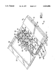
- FIG. 1 is an isometric view of a network interface device with the primary lid closed and the secondary lid opened illustrating the subscriber portion containing an array of subscriber modules containing the present invention
- FIG. 2 is an isometric view of a subscriber module with the plug removed from the jack and showing conductors extending to the module from premise wiring and from a distribution cable;
- FIG. 3 is a cross-sectional view of the plug fully inserted within the jack and an interconnecting contact interconnecting a pair of contacts therein;
- FIG. 4 is an isometric view of the plug in place within the jack and a stuffer cap lifted to its open position for termination of subscriber wiring;
- FIG. 5 is an isometric exploded view of the module of FIGS. 1 to 4 showing the circuit board with contacts and terminals mounted thereto and
- FIGS. 6 and 7 are an exploded isometric view and an exploded elevation view of an alternate embodiment of the present invention wherein each interconnecting contact of the plug interconnects a pair of side-by-side contacts, with a portion of the plug broken away in FIG. 6.
- network interface device 10 comprising an enclosure 12 having a subscriber portion 14 and a telephone company portion 16, with the enclosure 12 having a primary lid 18 secured at lock 20 to prevent access by non-service personnel to portion 16.
- a pair of distribution cables 22 are shown extending from portion 16.
- Secondary lid 30 is shown in the opened position and includes a lock 32 for being secured to primary lid 18 when closed, with an array of subscriber modules 40 mounted within subscriber portion 14.
- Individual subscriber cables 34 are shown extending from subscriber portion 14 of enclosure 12 that extend into the premises of the customer or subscriber, and the conductors 36 of each subscriber cable are electrically connected to circuits within an associated subscriber module 40 mounted in subscriber portion 14 of enclosure 12.
- Security covers 42 are seen in their open positions and are pivotally mounted at hinges 44 to respective modules 40 to be rotated to a closed position and thereafter locked if desired by the respective subscriber at lock locations 46, such as by using conventional Size 10 padlocks.
- Each module 40 includes a cable face 48 for connection of ends of conductors 36 of subscriber cables 34 to terminals within the module, and also provides electrical connections to conductors 38 extending to telephone company portion 16 for connection to conductors of a distribution cable 22.
- a plug 50 is affixed to module 40 such as by a lanyard 52 and includes a tab portion 54 extending upwardly from the module enabling manual gripping for removal of the plug from its respective jack.
- plug 50 is shown to have a polarized mating end 58 as is conventional with plug connectors in use in the telephone industry to connect telephones to premise wiring at conventional jacks having complementarily shaped plug-receiving cavities.
- Plug 50 is formed of dielectric material such as thermoplastic resin, and is seen to have four interconnecting contacts 56 affixed to mating face 58 at a mating end of the plug and including contact sections 60, 62 along side surfaces 64,66 connected by a body section 68.
- Interconnecting contacts 56 are seen disposed within corresponding grooves 70 secured therein such as by barbs 72 at ends of contact sections 60, 62.
- Plug 50 Spaced rearwardly from mating face 58 is an elastomeric sealing member 74 such as an O-ring seated in a groove 76 extending around intermediate section 78.
- Plug 50 also includes an enlarged diameter cover flange 80 to traverse and close the opening to jack 100.
- Jack 100 is defined by dielectric housing 98 of module 40 and includes a plug-receiving cavity 102 with a mating interface adjacent bottom 104 of the cavity.
- First contacts 106 are arrayed in respective grooves 108 along a first side 110 and second contacts 112 in grooves 114 along a second side 116, all having cantilever beam contact arms 118, 120 associated with contact sections 60, 62 of interconnecting contacts 56 of plug 50, extending toward cavity bottom 104 at angles into plug-receiving cavity 102 in opposed pairs to become electrically engaged by interconnecting contacts 56 and thus become interconnected to complete respective circuits upon full insertion of plug 50 into cavity 102.
- Annular surface portion 122 of enlarged diameter cavity portion 124 is engaged by sealing member 74 of plug 50 upon full insertion to define an environmental seal protecting the mating interface at the bottom of cavity 102.
- a friction fit of O-ring 74 against surface portion 122 is sufficient to retain plug 50 within jack 100 without a latching arrangement.
- Plug-receiving cavity 102 and contacts 106, 112 therein define a test port for receipt of a plug for testing of the circuits of the subscriber premise wiring and the distribution cable, and with plug 50 fully inserted thereinto is sealed.
- First contacts 106 include posts 126 extending through holes of circuit board 170 for soldering to associated traces (not shown) of board 170, and second contacts 110 similarly include posts 128 in holes of board 170 and are soldered to other traces of board 170.
- wire termination section 150 is seen to include a stuffer cap 152 disposed within a slot 154 and movable vertically between a pretermination or open position, and a termination or closed position, and that includes a grippable section 156 to be manipulated.
- Stuffer cap 152 is shown to have four wire-receiving sections 158 for receipt thereinto of ends of respective conductors 36 when in the open position, whereafter movement to the closed position moves the wires into support slots 160 of housing 98 and into insulation displacement slots 162 of terminals 164 in a manner generally conventionally known.
- Terminals 164 include post sections 166 and are mounted on a circuit board 170 traversing the bottom of module 40 (best seen in FIG. 5) and are electrically connected to respective traces thereon.
- circuit board 170 On circuit board 170, the traces from terminals 164 extend to respective ones of second contacts 112 of jack 100 and electrically connected thereto, thus completing circuits from the second contacts 112 to conductors 36 of the subscriber cable 34. Additional traces extend from first terminals 106 to terminations with conductors 38 that extend into telephone company portion 16 of network interface device 10 for connection to distribution cables 22.
- probe contacts 172 FIG. 5
- circuit board 170 have post sections and are mounted onto circuit board 170 joined to selected traces thereof and extending to exposed contact sections 174 within recesses 176 along accessible surface 178 of module 40 for testing by service personnel.
- Plug connector 200 includes a plug portion 202 having at its end 204 a pair of interconnecting contacts 206, 208 securable thereto.
- Each interconnecting contact 206, 208 includes a body portion 210 insertable into a complementary cavity 212 extending into plug portion 202, and body portion 210 includes a locking lance 214 that latches behind a ledge 216 along a side wall of cavity 212 upon full contact insertion to prevent interconnecting contact 206, 208 from dislodging.
- Contact section 218 is exposed, preferably in a shallow groove, along a side surface of plug portion 202 and continuing exposed along mating end 220 thereof for engagement with an associated pair of contacts 222, 224 of the jack (not shown) into which plug connector 200 is inserted, with contacts 222, 224 mounted side-by-side onto a circuit board 226.
- First contact 222 may be connected to the subscriber premise wiring while second contact 224 may be connected to a circuit of the distribution cable, both being associated with either the tip or ring circuit for the subscriber, with side-by-side contacts 222, 224 otherwise unconnected to each other until engaged by the contact section 218 of interconnecting contact 206.
- Contact section 218 of interconnecting contact 206 has a width great enough to span the distance comprising the spacing between contacts 222, 224 associated with interconnecting contact 206 and assuredly engage the deflectable spring arms 228, 2230 of the pair of contacts 222, 224 but not great enough to inadvertently engage a third contact such as contact 232.
- Interconnecting contact 208 likewise will interconnect side-by-side contacts 232, 234 such as for the other one of the tip or ring circuits.
- conductors 38 are connected to associated conductors of the cable in the telephone company portion 16 of the network interface device, by means of protector modules (not shown) such as are disclosed in U.S. Pat. No. 5,317,474.
- protector modules establish protection against surges of voltage and current along the circuits thus protecting equipment from damage.
- potting material 180 is disposed along the outwardly facing surface of the circuit board within board-receiving recess 182 into the bottom face of module 40, thus environmentally sealing the electrical connections within module 40.
- circuit board 170 within a subscriber module 40 that enables utilization of additional electrical or electronic components within the module, such as a maintenance test unit (not shown), or a half-ringer enabling computer polling of subscriber lines to the module for fault-free verification even in the absence of a telephone unit properly connected to premise wiring within the premises.
- a maintenance test unit not shown
- a half-ringer enabling computer polling of subscriber lines to the module for fault-free verification even in the absence of a telephone unit properly connected to premise wiring within the premises.
Abstract
Description
Claims (3)
Priority Applications (1)
| Application Number | Priority Date | Filing Date | Title |
|---|---|---|---|
| US08/587,690 US5625686A (en) | 1994-03-15 | 1996-01-17 | Customer-accessible test port for network interface device |
Applications Claiming Priority (3)
| Application Number | Priority Date | Filing Date | Title |
|---|---|---|---|
| US08/213,137 US5420920A (en) | 1994-03-15 | 1994-03-15 | Network interface device module providing sealed customer-accessible test port |
| US08/442,032 US5600716A (en) | 1994-03-15 | 1995-05-16 | Customer-accessible test port for network interface device |
| US08/587,690 US5625686A (en) | 1994-03-15 | 1996-01-17 | Customer-accessible test port for network interface device |
Related Parent Applications (1)
| Application Number | Title | Priority Date | Filing Date |
|---|---|---|---|
| US08/442,032 Continuation US5600716A (en) | 1994-03-15 | 1995-05-16 | Customer-accessible test port for network interface device |
Publications (1)
| Publication Number | Publication Date |
|---|---|
| US5625686A true US5625686A (en) | 1997-04-29 |
Family
ID=22793871
Family Applications (3)
| Application Number | Title | Priority Date | Filing Date |
|---|---|---|---|
| US08/213,137 Expired - Lifetime US5420920A (en) | 1994-03-15 | 1994-03-15 | Network interface device module providing sealed customer-accessible test port |
| US08/442,032 Expired - Fee Related US5600716A (en) | 1994-03-15 | 1995-05-16 | Customer-accessible test port for network interface device |
| US08/587,690 Expired - Fee Related US5625686A (en) | 1994-03-15 | 1996-01-17 | Customer-accessible test port for network interface device |
Family Applications Before (2)
| Application Number | Title | Priority Date | Filing Date |
|---|---|---|---|
| US08/213,137 Expired - Lifetime US5420920A (en) | 1994-03-15 | 1994-03-15 | Network interface device module providing sealed customer-accessible test port |
| US08/442,032 Expired - Fee Related US5600716A (en) | 1994-03-15 | 1995-05-16 | Customer-accessible test port for network interface device |
Country Status (13)
| Country | Link |
|---|---|
| US (3) | US5420920A (en) |
| EP (1) | EP0750823B1 (en) |
| JP (1) | JPH10502497A (en) |
| KR (1) | KR970701978A (en) |
| CN (1) | CN1084111C (en) |
| AU (1) | AU1917395A (en) |
| BR (1) | BR9507097A (en) |
| CA (1) | CA2185449A1 (en) |
| DE (1) | DE69512642T2 (en) |
| GR (1) | GR1002629B (en) |
| PH (1) | PH30838A (en) |
| TR (1) | TR28905A (en) |
| WO (1) | WO1995025405A1 (en) |
Cited By (11)
| Publication number | Priority date | Publication date | Assignee | Title |
|---|---|---|---|---|
| US6173055B1 (en) * | 1999-02-02 | 2001-01-09 | Avage Inc. | Security latch for network interface devices and plastic enclosures |
| US6246749B1 (en) * | 1997-01-31 | 2001-06-12 | The Whitaker Corporation | Network interface unit and module |
| US6322375B1 (en) * | 1997-09-29 | 2001-11-27 | Avaya Technology Corp. | Network interface device with circuit board architecture |
| WO2002087022A1 (en) * | 2001-04-23 | 2002-10-31 | Corning Cable Systems Llc | Wire termination device having test contacts on cover |
| US6535579B1 (en) * | 2000-05-31 | 2003-03-18 | Corning Cable Systems Llc | Network interface device with disconnectable half-ringer |
| US6570965B1 (en) * | 2000-11-02 | 2003-05-27 | Home Director, Inc. | Configurable telephone line distribution modules for designating primary and secondary telephone lines |
| US6599144B1 (en) * | 1998-12-24 | 2003-07-29 | Firma Ing. Walter Hengst Gmbh & Co. Kg | Sealed testable electrical contact arrangement |
| US6795552B1 (en) | 1999-12-14 | 2004-09-21 | Corning Cable Systems Llc | Enhanced services network interface device |
| WO2010016915A1 (en) * | 2008-08-06 | 2010-02-11 | Tyco Electronics Corporation | Card edge connector with idc wire termination |
| US20140321858A1 (en) * | 2003-01-31 | 2014-10-30 | Centurylink Intellectual Property Llc | Optical Network Termination Systems and Methods |
| US10142023B2 (en) | 2003-01-31 | 2018-11-27 | Centurylink Intellectual Property Llc | Antenna system and methods for wireless optical network termination |
Families Citing this family (47)
| Publication number | Priority date | Publication date | Assignee | Title |
|---|---|---|---|---|
| KR19980702155A (en) | 1995-02-09 | 1998-07-15 | 그레이스 스티븐 에스. | Epoxy Resin Compositions Curable at Low Temperatures |
| PT710040E (en) * | 1995-09-22 | 2002-02-28 | Pouyet Internat | CUTTING AND TESTING DEVICE FOR TELEPHONE LINE |
| AU1684497A (en) * | 1995-12-15 | 1997-07-14 | Whitaker Corporation, The | Test port jack for network interface device |
| US5667402A (en) * | 1995-12-15 | 1997-09-16 | Denovich; Sam | Wire carrier for electrical connector modular |
| US5857870A (en) * | 1995-12-22 | 1999-01-12 | The Whitaker Corporation | Electrical connector with switch subassembly |
| WO1997023928A1 (en) * | 1995-12-22 | 1997-07-03 | The Whitaker Corporation | Electrical connector with switch subassembly |
| US5995617A (en) * | 1996-05-09 | 1999-11-30 | Antec Corporation | Connector block mountable connector and telephone circuit |
| US5901220A (en) * | 1997-02-28 | 1999-05-04 | The Whitaker Corporation | Network interface device |
| FR2770037B1 (en) * | 1997-10-21 | 1999-12-17 | Pouyet Sa | INTERCONNECTION MODULE FOR TWO MONOPARY LINES |
| FR2776463B1 (en) * | 1998-03-19 | 2000-06-23 | Gilles Cassagne | ELEMENT ALLOWING THE INSTALLATION OF ELECTRIC OR ELECTRONIC TESTS |
| US6011831A (en) * | 1998-04-02 | 2000-01-04 | Antec Corporation | Network interface device having cavities for housing test circuitry |
| US6139333A (en) * | 1999-01-19 | 2000-10-31 | The Whitaker Corporation | Connector assembly with shunting switch |
| FR2808397B1 (en) * | 2000-04-28 | 2002-09-20 | Pouyet Sa | TEST AND CUT-OFF DEVICE FOR TELEPHONE OR COMPUTER LINE AND INTERCONNECTION MODULE PROVIDED WITH SUCH A DEVICE |
| US7388949B2 (en) | 2000-12-28 | 2008-06-17 | At&T Delaware Intellectual Property, Inc. | System and method for audio caller identification service |
| US6358093B1 (en) | 2001-02-07 | 2002-03-19 | Adc Telecommunications, Inc. | Normal through jack and method |
| US7254226B1 (en) * | 2001-05-08 | 2007-08-07 | At&T Intellectual Property, Inc. | Call waiting priority alert |
| US7085358B2 (en) | 2001-06-25 | 2006-08-01 | Bellsouth Intellectual Property Corporation | Visual caller identification |
| US7012999B2 (en) | 2001-06-25 | 2006-03-14 | Bellsouth Intellectual Property Corporation | Audio caller identification |
| US7315614B2 (en) | 2001-08-14 | 2008-01-01 | At&T Delaware Intellectual Property, Inc. | Remote notification of communications |
| US7403768B2 (en) * | 2001-08-14 | 2008-07-22 | At&T Delaware Intellectual Property, Inc. | Method for using AIN to deliver caller ID to text/alpha-numeric pagers as well as other wireless devices, for calls delivered to wireless network |
| US7269249B2 (en) | 2001-09-28 | 2007-09-11 | At&T Bls Intellectual Property, Inc. | Systems and methods for providing user profile information in conjunction with an enhanced caller information system |
| US7079837B1 (en) * | 2001-11-06 | 2006-07-18 | Bellsouth Intellectual Property Corporation | Caller identification queue for wireless telephones |
| US7315618B1 (en) | 2001-12-27 | 2008-01-01 | At&T Bls Intellectual Property, Inc. | Voice caller ID |
| US7385992B1 (en) | 2002-05-13 | 2008-06-10 | At&T Delaware Intellectual Property, Inc. | Internet caller-ID integration |
| US7586898B1 (en) | 2002-05-13 | 2009-09-08 | At&T Intellectual Property, I, L.P. | Third party content for internet caller-ID messages |
| US7139374B1 (en) | 2002-07-23 | 2006-11-21 | Bellsouth Intellectual Property Corp. | System and method for gathering information related to a geographical location of a callee in a public switched telephone network |
| US7623645B1 (en) | 2002-07-23 | 2009-11-24 | At&T Intellectual Property, I, L.P. | System and method for gathering information related to a geographical location of a caller in a public switched telephone network |
| US6943508B2 (en) * | 2002-09-23 | 2005-09-13 | Otis Elevator Company | Tubular linear synchronous motor control for elevator doors |
| US7463727B2 (en) | 2003-04-18 | 2008-12-09 | At&T International Property, I, L.P. | Caller ID messaging device |
| US7978833B2 (en) | 2003-04-18 | 2011-07-12 | At&T Intellectual Property I, L.P. | Private caller ID messaging |
| US7280646B2 (en) | 2003-04-18 | 2007-10-09 | At&T Bls Intellectual Property, Inc. | Dynamic Caller ID messaging |
| US7283625B2 (en) | 2003-04-18 | 2007-10-16 | At&T Bls Intellectual Property, Inc. | Caller ID messaging telecommunications services |
| US7443964B2 (en) | 2003-04-18 | 2008-10-28 | At&T Intellectual Property, I,L.P. | Caller ID messaging |
| US7269412B2 (en) | 2003-05-29 | 2007-09-11 | At&T Bls Intellectual Property, Inc. | Caller identification device and method of operation thereof |
| US7609832B2 (en) | 2003-11-06 | 2009-10-27 | At&T Intellectual Property, I,L.P. | Real-time client survey systems and methods |
| US7623849B2 (en) * | 2003-11-13 | 2009-11-24 | At&T Intellectual Property, I, L.P. | Method, system, and storage medium for providing comprehensive originator identification services |
| US7672444B2 (en) * | 2003-12-24 | 2010-03-02 | At&T Intellectual Property, I, L.P. | Client survey systems and methods using caller identification information |
| US8195136B2 (en) | 2004-07-15 | 2012-06-05 | At&T Intellectual Property I, L.P. | Methods of providing caller identification information and related registries and radiotelephone networks |
| US7672450B2 (en) * | 2004-09-09 | 2010-03-02 | Calix Networks, Inc. | Network interface device enclosure |
| US7652390B2 (en) * | 2004-12-28 | 2010-01-26 | Calix Networks, Inc. | Network interface device communication via power line |
| US7287990B1 (en) * | 2006-07-21 | 2007-10-30 | At&T Corp. | Method and apparatus for grounding a cable |
| US8160226B2 (en) | 2007-08-22 | 2012-04-17 | At&T Intellectual Property I, L.P. | Key word programmable caller ID |
| US8243909B2 (en) | 2007-08-22 | 2012-08-14 | At&T Intellectual Property I, L.P. | Programmable caller ID |
| US20090060168A1 (en) * | 2007-08-31 | 2009-03-05 | Corry Charles D | Network interface |
| US8981220B2 (en) * | 2010-05-27 | 2015-03-17 | Qwest Communications International Inc. | Universal cable adapter |
| WO2014069285A1 (en) | 2012-10-30 | 2014-05-08 | 矢崎総業株式会社 | Connector |
| US9608363B2 (en) * | 2015-07-24 | 2017-03-28 | Magna Powertrain, Inc. | Sealing insert for electrical connectors |
Citations (32)
| Publication number | Priority date | Publication date | Assignee | Title |
|---|---|---|---|---|
| EP0127349A2 (en) * | 1983-05-31 | 1984-12-05 | AMP INCORPORATED (a New Jersey corporation) | Network interface device |
| US4488008A (en) * | 1983-06-24 | 1984-12-11 | Siecor Corporation | Telephone network interface device |
| US4562311A (en) * | 1983-07-29 | 1985-12-31 | Amp Incorporated | Telephone network interface device |
| GB2161996A (en) * | 1984-07-18 | 1986-01-22 | Amp Inc | Bipartite electrical connector with sealing means |
| US4588238A (en) * | 1984-12-19 | 1986-05-13 | Gte Products Corporation | Telephone network interface connector |
| US4647725A (en) * | 1985-03-11 | 1987-03-03 | Siecor Corporation | Indoor type telephone network interface device |
| US4726787A (en) * | 1986-12-22 | 1988-02-23 | Amp Incorporated | Miniature electrical shunt connector |
| US4741032A (en) * | 1986-03-17 | 1988-04-26 | Siecor Corporation | Container for telephone network interface device |
| US4749359A (en) * | 1987-08-27 | 1988-06-07 | Siecor Corporation | Security override network interface device |
| US4800588A (en) * | 1985-08-07 | 1989-01-24 | Gte Products Corporation | Telephone network interface system |
| US4809323A (en) * | 1988-03-04 | 1989-02-28 | Keptel, Inc. | Telephone network interface apparatus |
| US4827504A (en) * | 1987-03-04 | 1989-05-02 | Keptel, Inc. | Network interface enclosure |
| US4910770A (en) * | 1986-06-30 | 1990-03-20 | Keptel, Inc. | Network interface device and enclosure |
| US4919544A (en) * | 1989-01-05 | 1990-04-24 | Keptel, Inc. | Retrofit telephone network interface apparatus |
| US4932051A (en) * | 1989-08-07 | 1990-06-05 | Keptel, Inc. | Telephone network interface apparatus |
| US4945559A (en) * | 1987-12-30 | 1990-07-31 | Keptel, Inc. | Telephone network interface apparatus |
| US4945560A (en) * | 1988-04-29 | 1990-07-31 | Keptel, Inc. | Telephone network interface apparatus |
| US4949376A (en) * | 1989-06-15 | 1990-08-14 | Keptel, Inc. | Telephone network interface apparatus |
| US4952170A (en) * | 1989-02-23 | 1990-08-28 | Amp Incorporated | Shunted connector assembly and interdigitated shunt assembly therefor |
| US4979209A (en) * | 1987-12-30 | 1990-12-18 | Keptel, Inc. | Individual subscriber line module |
| WO1992004794A2 (en) * | 1990-09-04 | 1992-03-19 | Raychem Corporation | Alarm and test system for a digital main line |
| US5106306A (en) * | 1991-01-29 | 1992-04-21 | Telephone Products, Inc. | Rotary electrical connector with remote modular connector |
| US5153910A (en) * | 1990-05-15 | 1992-10-06 | Gte Products Corporation | Protected telephone network interface device |
| US5207583A (en) * | 1992-02-28 | 1993-05-04 | Siecor Corporation | Network interface unit |
| US5260994A (en) * | 1991-09-25 | 1993-11-09 | Reliance Comm/Tec Corporation | Maintenance termination unit module |
| WO1993023960A2 (en) * | 1992-05-12 | 1993-11-25 | Raychem Corporation | Telecommunications network interface assembly |
| US5291553A (en) * | 1992-04-10 | 1994-03-01 | Tll Industries, Inc. | Weatherproof telephone network interface modules |
| US5297199A (en) * | 1992-02-20 | 1994-03-22 | Keptel, Inc. | Apparatus for connecting and disconnecting subscriber premises line and incoming telephone company line |
| US5295865A (en) * | 1991-09-12 | 1994-03-22 | Yazaki Corporation | Rubber plug for waterproof connector |
| US5312266A (en) * | 1992-12-09 | 1994-05-17 | At&T Bell Laboratories | Tamperproof interconnection apparatus |
| US5317474A (en) * | 1992-05-08 | 1994-05-31 | The Whitaker Corporation | Module for telephone line conductor pair having single protector unit |
| US5333193A (en) * | 1990-05-15 | 1994-07-26 | Siecor Puerto Rico, Inc. | Telephone network termination module having insulation displacement terminals |
-
1994
- 1994-03-15 US US08/213,137 patent/US5420920A/en not_active Expired - Lifetime
-
1995
- 1995-01-18 PH PH49792A patent/PH30838A/en unknown
- 1995-01-25 GR GR950100023A patent/GR1002629B/en unknown
- 1995-02-13 EP EP95911703A patent/EP0750823B1/en not_active Expired - Lifetime
- 1995-02-13 BR BR9507097A patent/BR9507097A/en not_active Application Discontinuation
- 1995-02-13 WO PCT/US1995/001802 patent/WO1995025405A1/en active IP Right Grant
- 1995-02-13 CA CA002185449A patent/CA2185449A1/en not_active Abandoned
- 1995-02-13 DE DE69512642T patent/DE69512642T2/en not_active Expired - Lifetime
- 1995-02-13 KR KR1019960705033A patent/KR970701978A/en not_active Application Discontinuation
- 1995-02-13 AU AU19173/95A patent/AU1917395A/en not_active Abandoned
- 1995-02-13 JP JP7524024A patent/JPH10502497A/en active Pending
- 1995-02-13 CN CN95192716A patent/CN1084111C/en not_active Expired - Fee Related
- 1995-03-01 TR TR00208/95A patent/TR28905A/en unknown
- 1995-05-16 US US08/442,032 patent/US5600716A/en not_active Expired - Fee Related
-
1996
- 1996-01-17 US US08/587,690 patent/US5625686A/en not_active Expired - Fee Related
Patent Citations (34)
| Publication number | Priority date | Publication date | Assignee | Title |
|---|---|---|---|---|
| EP0127349A2 (en) * | 1983-05-31 | 1984-12-05 | AMP INCORPORATED (a New Jersey corporation) | Network interface device |
| US4500158A (en) * | 1983-05-31 | 1985-02-19 | Amp Incorporated | Network interface device |
| US4488008A (en) * | 1983-06-24 | 1984-12-11 | Siecor Corporation | Telephone network interface device |
| US4562311A (en) * | 1983-07-29 | 1985-12-31 | Amp Incorporated | Telephone network interface device |
| GB2161996A (en) * | 1984-07-18 | 1986-01-22 | Amp Inc | Bipartite electrical connector with sealing means |
| US4588238A (en) * | 1984-12-19 | 1986-05-13 | Gte Products Corporation | Telephone network interface connector |
| US4647725A (en) * | 1985-03-11 | 1987-03-03 | Siecor Corporation | Indoor type telephone network interface device |
| US4800588A (en) * | 1985-08-07 | 1989-01-24 | Gte Products Corporation | Telephone network interface system |
| US4741032A (en) * | 1986-03-17 | 1988-04-26 | Siecor Corporation | Container for telephone network interface device |
| US4910770A (en) * | 1986-06-30 | 1990-03-20 | Keptel, Inc. | Network interface device and enclosure |
| US4726787A (en) * | 1986-12-22 | 1988-02-23 | Amp Incorporated | Miniature electrical shunt connector |
| US4827504A (en) * | 1987-03-04 | 1989-05-02 | Keptel, Inc. | Network interface enclosure |
| US4749359A (en) * | 1987-08-27 | 1988-06-07 | Siecor Corporation | Security override network interface device |
| US4945559A (en) * | 1987-12-30 | 1990-07-31 | Keptel, Inc. | Telephone network interface apparatus |
| US4979209A (en) * | 1987-12-30 | 1990-12-18 | Keptel, Inc. | Individual subscriber line module |
| US4809323A (en) * | 1988-03-04 | 1989-02-28 | Keptel, Inc. | Telephone network interface apparatus |
| US4945560A (en) * | 1988-04-29 | 1990-07-31 | Keptel, Inc. | Telephone network interface apparatus |
| US4919544A (en) * | 1989-01-05 | 1990-04-24 | Keptel, Inc. | Retrofit telephone network interface apparatus |
| US4952170A (en) * | 1989-02-23 | 1990-08-28 | Amp Incorporated | Shunted connector assembly and interdigitated shunt assembly therefor |
| US4949376A (en) * | 1989-06-15 | 1990-08-14 | Keptel, Inc. | Telephone network interface apparatus |
| US4932051A (en) * | 1989-08-07 | 1990-06-05 | Keptel, Inc. | Telephone network interface apparatus |
| US5153910A (en) * | 1990-05-15 | 1992-10-06 | Gte Products Corporation | Protected telephone network interface device |
| US5333193A (en) * | 1990-05-15 | 1994-07-26 | Siecor Puerto Rico, Inc. | Telephone network termination module having insulation displacement terminals |
| WO1992004794A2 (en) * | 1990-09-04 | 1992-03-19 | Raychem Corporation | Alarm and test system for a digital main line |
| US5106306A (en) * | 1991-01-29 | 1992-04-21 | Telephone Products, Inc. | Rotary electrical connector with remote modular connector |
| US5295865A (en) * | 1991-09-12 | 1994-03-22 | Yazaki Corporation | Rubber plug for waterproof connector |
| US5260994A (en) * | 1991-09-25 | 1993-11-09 | Reliance Comm/Tec Corporation | Maintenance termination unit module |
| US5297199A (en) * | 1992-02-20 | 1994-03-22 | Keptel, Inc. | Apparatus for connecting and disconnecting subscriber premises line and incoming telephone company line |
| US5207583A (en) * | 1992-02-28 | 1993-05-04 | Siecor Corporation | Network interface unit |
| US5291553A (en) * | 1992-04-10 | 1994-03-01 | Tll Industries, Inc. | Weatherproof telephone network interface modules |
| US5317474A (en) * | 1992-05-08 | 1994-05-31 | The Whitaker Corporation | Module for telephone line conductor pair having single protector unit |
| WO1993023960A2 (en) * | 1992-05-12 | 1993-11-25 | Raychem Corporation | Telecommunications network interface assembly |
| US5359654A (en) * | 1992-05-12 | 1994-10-25 | Raychem Corporation | Telecommunications network interface assembly |
| US5312266A (en) * | 1992-12-09 | 1994-05-17 | At&T Bell Laboratories | Tamperproof interconnection apparatus |
Non-Patent Citations (26)
| Title |
|---|
| International Search Report dated May 31, 1995 in PCT Application corresponding to parent application Ser. No. 08/213,137. * |
| Keptel Brochure, "INI-1900 Indoor Network Interface System", (1989), two pages; Keptel, Inc., Tinton Falls, New Jersey. |
| Keptel Brochure, "Installation Instructions, Line Interface Module IV Jumping Jack", one sheet, containing notation May 1994; Keptel, Inc., Tinton Falls, NJ. |
| Keptel Brochure, "SNI-1212 Network Interface System", (date unknown), one page; Keptel, Inc., Tinton Falls, New Jersey. |
| Keptel Brochure, "SNI-1500 Indoor Network Interface", (1989), two pages; Keptel, Inc., Tinton Falls, New Jersey. |
| Keptel Brochure, "SNI-4600", (1988), two pages; Keptel, Inc., Tinton Falls, New Jersey. |
| Keptel Brochure, "SNI-8925 25 Line Indoor Netwrok Interface", (1989), two pages; Keptel, Inc., Tinton Falls, New Jersey. |
| Keptel Brochure, INI 1900 Indoor Network Interface System , (1989), two pages; Keptel, Inc., Tinton Falls, New Jersey. * |
| Keptel Brochure, Installation Instructions, Line Interface Module IV Jumping Jack , one sheet, containing notation May 1994; Keptel, Inc., Tinton Falls, NJ. * |
| Keptel Brochure, SNI 1212 Network Interface System , (date unknown), one page; Keptel, Inc., Tinton Falls, New Jersey. * |
| Keptel Brochure, SNI 1500 Indoor Network Interface , (1989), two pages; Keptel, Inc., Tinton Falls, New Jersey. * |
| Keptel Brochure, SNI 4600 , (1988), two pages; Keptel, Inc., Tinton Falls, New Jersey. * |
| Keptel Brochure, SNI 8925 25 Line Indoor Netwrok Interface , (1989), two pages; Keptel, Inc., Tinton Falls, New Jersey. * |
| One photograph, "Line Interface Module IV", Part No. 91734-00; product of Keptel, Inc., Tinton Falls, NJ. |
| One photograph, Line Interface Module IV , Part No. 91734 00; product of Keptel, Inc., Tinton Falls, NJ. * |
| Search Report dated Aug. 10, 1995 in corresponding Greek application. * |
| Siecor Brochure, "630 and 631 Multifunction Indoor Network Interfaces", (1987), two pages; Siecor Corporation, Keller, Texas. |
| Siecor Brochure, "CAC 1000 and 1001 Outdoor Network Interfaces", (1987), two pages; Siecor Corporation, Keller, Texas. |
| Siecor Brochure, "CAC 3000 Outdoor Network Interface", (1988), two pages;Siecor Corporation, Keller Texas. |
| Siecor Brochure, "CAC 7600 Outdoor Network Interface Device", (1990), two pages; Siecor Corporation, Keller, Texas. |
| Siecor Brochure, "MLP600 Series", (1989), two pages; Siecor Corporation, Keller, Texas. |
| Siecor Brochure, 630 and 631 Multifunction Indoor Network Interfaces , (1987), two pages; Siecor Corporation, Keller, Texas. * |
| Siecor Brochure, CAC 1000 and 1001 Outdoor Network Interfaces , (1987), two pages; Siecor Corporation, Keller, Texas. * |
| Siecor Brochure, CAC 3000 Outdoor Network Interface , (1988), two pages;Siecor Corporation, Keller Texas. * |
| Siecor Brochure, CAC 7600 Outdoor Network Interface Device , (1990), two pages; Siecor Corporation, Keller, Texas. * |
| Siecor Brochure, MLP600 Series , (1989), two pages; Siecor Corporation, Keller, Texas. * |
Cited By (11)
| Publication number | Priority date | Publication date | Assignee | Title |
|---|---|---|---|---|
| US6246749B1 (en) * | 1997-01-31 | 2001-06-12 | The Whitaker Corporation | Network interface unit and module |
| US6322375B1 (en) * | 1997-09-29 | 2001-11-27 | Avaya Technology Corp. | Network interface device with circuit board architecture |
| US6599144B1 (en) * | 1998-12-24 | 2003-07-29 | Firma Ing. Walter Hengst Gmbh & Co. Kg | Sealed testable electrical contact arrangement |
| US6173055B1 (en) * | 1999-02-02 | 2001-01-09 | Avage Inc. | Security latch for network interface devices and plastic enclosures |
| US6795552B1 (en) | 1999-12-14 | 2004-09-21 | Corning Cable Systems Llc | Enhanced services network interface device |
| US6535579B1 (en) * | 2000-05-31 | 2003-03-18 | Corning Cable Systems Llc | Network interface device with disconnectable half-ringer |
| US6570965B1 (en) * | 2000-11-02 | 2003-05-27 | Home Director, Inc. | Configurable telephone line distribution modules for designating primary and secondary telephone lines |
| WO2002087022A1 (en) * | 2001-04-23 | 2002-10-31 | Corning Cable Systems Llc | Wire termination device having test contacts on cover |
| US20140321858A1 (en) * | 2003-01-31 | 2014-10-30 | Centurylink Intellectual Property Llc | Optical Network Termination Systems and Methods |
| US10142023B2 (en) | 2003-01-31 | 2018-11-27 | Centurylink Intellectual Property Llc | Antenna system and methods for wireless optical network termination |
| WO2010016915A1 (en) * | 2008-08-06 | 2010-02-11 | Tyco Electronics Corporation | Card edge connector with idc wire termination |
Also Published As
| Publication number | Publication date |
|---|---|
| JPH10502497A (en) | 1998-03-03 |
| CN1084111C (en) | 2002-05-01 |
| DE69512642T2 (en) | 2000-04-20 |
| GR1002629B (en) | 1997-03-03 |
| WO1995025405A1 (en) | 1995-09-21 |
| TR28905A (en) | 1997-07-17 |
| US5420920A (en) | 1995-05-30 |
| EP0750823A1 (en) | 1997-01-02 |
| EP0750823B1 (en) | 1999-10-06 |
| BR9507097A (en) | 1997-09-23 |
| AU1917395A (en) | 1995-10-03 |
| PH30838A (en) | 1997-11-03 |
| CA2185449A1 (en) | 1995-09-21 |
| US5600716A (en) | 1997-02-04 |
| KR970701978A (en) | 1997-04-12 |
| GR950100023A (en) | 1995-11-30 |
| CN1146843A (en) | 1997-04-02 |
| DE69512642D1 (en) | 1999-11-11 |
Similar Documents
| Publication | Publication Date | Title |
|---|---|---|
| US5625686A (en) | Customer-accessible test port for network interface device | |
| US5901220A (en) | Network interface device | |
| US5667402A (en) | Wire carrier for electrical connector modular | |
| US6028928A (en) | Telephone subscriber line module | |
| EP0487893B1 (en) | Modular jack patching device | |
| US5797759A (en) | Modular telecommunications terminal block | |
| RU2133071C1 (en) | Modified cross-connection system for telecommunication lines | |
| US6767257B2 (en) | Communication jack that withstands insertion of a communication plug that the jack is not specifically configured to mate with without being damage | |
| US5074801A (en) | Modular jack patching device | |
| EP1271967A2 (en) | Sealed terminating device | |
| US5567173A (en) | Electrical connector | |
| US5153988A (en) | Method of making modular telecommunications terminal block | |
| US7168992B2 (en) | Wire termination device having test contacts on cover | |
| US5207583A (en) | Network interface unit | |
| JPH09115576A (en) | Terminating device for telecommunication and data technique | |
| US4099819A (en) | Modular termination system for telecommunication devices | |
| WO1999004455A1 (en) | Distribution or cross-connection assembly | |
| KR100530429B1 (en) | Improved interface cards for use in telecommunication networks | |
| US5317474A (en) | Module for telephone line conductor pair having single protector unit | |
| US5470250A (en) | Bridging terminal block | |
| US4861287A (en) | Telephone network multiple transmission line interface | |
| US6185083B1 (en) | Protected telecommunication test adapter module | |
| US5964614A (en) | Connector with built-in safety feature | |
| WO1997023021A1 (en) | Test port jack for network interface device | |
| CA1284832C (en) | Telecommunications connector |
Legal Events
| Date | Code | Title | Description |
|---|---|---|---|
| REMI | Maintenance fee reminder mailed | ||
| LAPS | Lapse for failure to pay maintenance fees | ||
| FP | Lapsed due to failure to pay maintenance fee |
Effective date: 20010429 |
|
| AS | Assignment |
Owner name: THE WHITAKER LLC, DELAWARE Free format text: CERTIFICATE OF CONVERSION;ASSIGNOR:THE WHITAKER CORPORATION;REEL/FRAME:036907/0836 Effective date: 20100805 |
|
| AS | Assignment |
Owner name: COMMSCOPE EMEA LIMITED, IRELAND Free format text: ASSIGNMENT OF ASSIGNORS INTEREST;ASSIGNOR:THE WHITAKER LLC;REEL/FRAME:036942/0001 Effective date: 20150824 |
|
| AS | Assignment |
Owner name: COMMSCOPE TECHNOLOGIES LLC, NORTH CAROLINA Free format text: ASSIGNMENT OF ASSIGNORS INTEREST;ASSIGNOR:COMMSCOPE EMEA LIMITED;REEL/FRAME:037012/0001 Effective date: 20150828 |
|
| STCH | Information on status: patent discontinuation |
Free format text: PATENT EXPIRED DUE TO NONPAYMENT OF MAINTENANCE FEES UNDER 37 CFR 1.362 |