US5627827A - Automatic service cutover for ISDN private exchange - Google Patents
Automatic service cutover for ISDN private exchange Download PDFInfo
- Publication number
- US5627827A US5627827A US08/234,548 US23454894A US5627827A US 5627827 A US5627827 A US 5627827A US 23454894 A US23454894 A US 23454894A US 5627827 A US5627827 A US 5627827A
- Authority
- US
- United States
- Prior art keywords
- port
- exchange
- digital
- connection
- circuit
- Prior art date
- Legal status (The legal status is an assumption and is not a legal conclusion. Google has not performed a legal analysis and makes no representation as to the accuracy of the status listed.)
- Expired - Fee Related
Links
Images


Classifications
-
- H—ELECTRICITY
- H04—ELECTRIC COMMUNICATION TECHNIQUE
- H04M—TELEPHONIC COMMUNICATION
- H04M3/00—Automatic or semi-automatic exchanges
- H04M3/42—Systems providing special services or facilities to subscribers
- H04M3/42314—Systems providing special services or facilities to subscribers in private branch exchanges
-
- H—ELECTRICITY
- H04—ELECTRIC COMMUNICATION TECHNIQUE
- H04Q—SELECTING
- H04Q11/00—Selecting arrangements for multiplex systems
- H04Q11/04—Selecting arrangements for multiplex systems for time-division multiplexing
- H04Q11/0428—Integrated services digital network, i.e. systems for transmission of different types of digitised signals, e.g. speech, data, telecentral, television signals
-
- H—ELECTRICITY
- H04—ELECTRIC COMMUNICATION TECHNIQUE
- H04M—TELEPHONIC COMMUNICATION
- H04M3/00—Automatic or semi-automatic exchanges
- H04M3/40—Applications of speech amplifiers
-
- H—ELECTRICITY
- H04—ELECTRIC COMMUNICATION TECHNIQUE
- H04M—TELEPHONIC COMMUNICATION
- H04M3/00—Automatic or semi-automatic exchanges
- H04M3/42—Systems providing special services or facilities to subscribers
- H04M3/428—Arrangements for placing incoming calls on hold
-
- H—ELECTRICITY
- H04—ELECTRIC COMMUNICATION TECHNIQUE
- H04M—TELEPHONIC COMMUNICATION
- H04M3/00—Automatic or semi-automatic exchanges
- H04M3/42—Systems providing special services or facilities to subscribers
- H04M3/56—Arrangements for connecting several subscribers to a common circuit, i.e. affording conference facilities
-
- H—ELECTRICITY
- H04—ELECTRIC COMMUNICATION TECHNIQUE
- H04M—TELEPHONIC COMMUNICATION
- H04M3/00—Automatic or semi-automatic exchanges
- H04M3/42—Systems providing special services or facilities to subscribers
- H04M3/58—Arrangements for transferring received calls from one subscriber to another; Arrangements affording interim conversations between either the calling or the called party and a third party
-
- H—ELECTRICITY
- H04—ELECTRIC COMMUNICATION TECHNIQUE
- H04Q—SELECTING
- H04Q2213/00—Indexing scheme relating to selecting arrangements in general and for multiplex systems
- H04Q2213/13003—Constructional details of switching devices
-
- H—ELECTRICITY
- H04—ELECTRIC COMMUNICATION TECHNIQUE
- H04Q—SELECTING
- H04Q2213/00—Indexing scheme relating to selecting arrangements in general and for multiplex systems
- H04Q2213/13034—A/D conversion, code compression/expansion
-
- H—ELECTRICITY
- H04—ELECTRIC COMMUNICATION TECHNIQUE
- H04Q—SELECTING
- H04Q2213/00—Indexing scheme relating to selecting arrangements in general and for multiplex systems
- H04Q2213/13106—Microprocessor, CPU
-
- H—ELECTRICITY
- H04—ELECTRIC COMMUNICATION TECHNIQUE
- H04Q—SELECTING
- H04Q2213/00—Indexing scheme relating to selecting arrangements in general and for multiplex systems
- H04Q2213/13202—Network termination [NT]
-
- H—ELECTRICITY
- H04—ELECTRIC COMMUNICATION TECHNIQUE
- H04Q—SELECTING
- H04Q2213/00—Indexing scheme relating to selecting arrangements in general and for multiplex systems
- H04Q2213/13209—ISDN
-
- H—ELECTRICITY
- H04—ELECTRIC COMMUNICATION TECHNIQUE
- H04Q—SELECTING
- H04Q2213/00—Indexing scheme relating to selecting arrangements in general and for multiplex systems
- H04Q2213/1322—PBX
-
- H—ELECTRICITY
- H04—ELECTRIC COMMUNICATION TECHNIQUE
- H04Q—SELECTING
- H04Q2213/00—Indexing scheme relating to selecting arrangements in general and for multiplex systems
- H04Q2213/1329—Asynchronous transfer mode, ATM
-
- H—ELECTRICITY
- H04—ELECTRIC COMMUNICATION TECHNIQUE
- H04Q—SELECTING
- H04Q2213/00—Indexing scheme relating to selecting arrangements in general and for multiplex systems
- H04Q2213/13299—Bus
-
- H—ELECTRICITY
- H04—ELECTRIC COMMUNICATION TECHNIQUE
- H04Q—SELECTING
- H04Q2213/00—Indexing scheme relating to selecting arrangements in general and for multiplex systems
- H04Q2213/1332—Logic circuits
-
- H—ELECTRICITY
- H04—ELECTRIC COMMUNICATION TECHNIQUE
- H04Q—SELECTING
- H04Q2213/00—Indexing scheme relating to selecting arrangements in general and for multiplex systems
- H04Q2213/13322—Integrated circuits
-
- H—ELECTRICITY
- H04—ELECTRIC COMMUNICATION TECHNIQUE
- H04Q—SELECTING
- H04Q2213/00—Indexing scheme relating to selecting arrangements in general and for multiplex systems
- H04Q2213/13362—Asynchronous systems
-
- H—ELECTRICITY
- H04—ELECTRIC COMMUNICATION TECHNIQUE
- H04Q—SELECTING
- H04Q2213/00—Indexing scheme relating to selecting arrangements in general and for multiplex systems
- H04Q2213/13405—Dual frequency signaling, DTMF
Definitions
- the present invention pertains to private exchanges and, more particularly, to a basic rate private exchange for interfacing between a digital network local exchange such as the Integrated Services Digital Network (ISDN) and a wide variety of different types of subscriber station devices. More particularly, it pertains to a mechanism to arrange for automatic cutover, or changeover, from older, analog Plain Old Telephone Service (POTS) to the more advanced ISDN basic rate service.
- ISDN Integrated Services Digital Network
- POTS Plain Old Telephone Service
- the Integrated Services Digital Network is :a world-wide telephone industry standard for the delivery of digital telephony services.
- BBI Basic Rate Interface
- ISDN can utilize most existing two-wire local exchange loops.
- the ISDN basic rate interface provides full duplex, 160,000-bit per second service through an encoding and signaling technique known as 2B1Q. Either 2B1Q or other similar encoding techniques are used outside of North America.
- CCITT ISDN specifications have defined several interface reference points in the ISDN..
- the customer end of the two wire local exchange loop is known as the "U" reference point which connects to a network local exchange LE.
- the 160,000-bit per second bandwidth is subdivided into one 16,000-bit per second signaling and packet data D channel, two 64,000-bit per second bearer B channels and one 16,000-bit per second maintenance M channel.
- the U reference interface must be terminated by a device known as a Network Termination-1 (NT-1).
- the NT-1 processes the information in maintenance channel M and converts the two-wire full duplex interface into a four-wire duplex interface including two two-wire simplex interfaces.
- the four-wire downstream interface provided by the NT-1 is known as the "S/T" reference point.
- all ISDN Customer Premises Equipment connects at the S/T reference point.
- a single device will accept the "U" input and synthesize an analog phone connection, with necessary translation from the standard analog service to the more complex ISDN interface.
- Signaling activity performing the functions of call setup, call progress and data link establishment, for BRI of the ISDN is performed by a complex protocol of information packet exchanges across the signaling channel D between the local exchange and the customer premises equipment.
- This signaling activity is sufficiently complex to require the services of a powerful microcomputer and a large,. complex set of software instructions contained within the customer premises equipment.
- a difficulty encountered in marketing a digital network private exchange is that the ISDN U and S/T reference interface points are functionally incompatible with the existing analog POTS. None of the existing POTS customer premises equipment, such as telephones, answering machines, PBXs facsimile devices and modems can operate if they are attached directly to either the U or the S/T ISDN reference points.
- the primary method for telephony users to connect to an ISDN basic rate interface is through entirely new digital S/T reference interface customer premises equipment. Due to many factors, such as the complexity of ISDN basic rate interface signaling protocols, the digital S/T reference interface; customer premises equipment has proven to be very expensive, often on the order of ten times the cost of POTS customer premises equipment. Additionally, in North America the ISDN user is responsible for the cost of supplying and installing the ISDN basic rate interface NT-1 device, and providing main power and power backup devices necessary to supply reliable DC power to the attached S/T reference interface customer premises equipment.
- This ISDN customer premises equipment includes telephones, adapters for personal computers and various self-contained data interface units. Some of this customer premises equipment supports both data and voice operations, and others include support for analog POTS customer premises equipment.
- this existing customer premises equipment does not provide a sufficient degree of access integration for existing POTS and data customer premises equipment to ISDN basic rate interface, and they do not include adequate access functions required for such integration, More importantly, it is the burden of the customer to coordinate the changeover of an existing analog line (with all the phone devices attached thereto) into the newer digital service, for which his present phone devices are unsuitable.
- the present invention provides a means to control existing POTS customer premises equipment access redefinition in a changeover to an ISDN basic rate interface.
- the described invention permits access to ISDN voice and data services without requiring a change in the existing POTS customer premises equipment and allows nearly continuous phone operations through automatic changeover.
- the private exchange device includes a detector for detecting whether the port connected to the local exchange is connected to an ISDN network or to a conventional network. If the system detects that it is connected to a conventional analog network, an ISDN control circuit used for communicating with the ISDN network is bypassed, and an analog telephone port is connected directly to the analog exchange.
- the ISDN private exchange apparatus detects the ISDN switch utilized by the local exchange and is further adapted to thereby automatically communicate with the local exchange according to the particular switch used at the local exchange.
- the present invention provides a versatile, low cost, basic rate ISDN local exchange interface device which can be readily installed by a non-technical user in a residential or small business environment and provides extensive hardware functionality in a fully integrated package.
- a private exchange according to the invention connects to the bare copper pair access point at the customer end of the subscriber loop, and performs the network interface functions required under CCITT standards.
- the private exchange provides a great deal of versatility in connecting POTS devices to an ISDN local exchange.
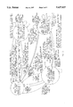
- FIG. 1 is a combined circuit schematic and block diagram of an ISDN private exchange, with network for automatic detection and changeover logic, according to the invention
- FIG. 2 is a state diagram of the changeover decision machine
- FIGS. 3 and 4 are state diagrams of a ring detection state machine.
- FIG. 4A is a first portion of the state diagram in FIG. 4.
- FIG. 4B is a second portion of the state diagram in FIG. 4.
- an ISDN private exchange 24 is illustrated in FIG. 1.
- An example of a private exchange is described in co-pending commonly assigned International Patent Application No. WO 95/22218, entitled PRIVATE EXCHANGE FOR ISDN, published Sep. 14, 1995 the disclosure of which is incorporated herein by reference. In general, reference numerals are commonly used between the present application and said co-pending application.
- the private exchange includes a port 26 for connection to an ISDN local exchange LE at the "U" boundary.
- the preferred embodiment is illustrated with reference to an integrated services digital network, those skilled in the art will recognize that the invention may be advantageously utilized for communication with any intelligent connection to a digital line exchange which uses a digital carrier.
- the private exchange may be connected to a digital cable service, a digital cellular phone service, or the like.
- private exchange circuit 24 also includes at least one analog port 30 for connection to analog subscriber devices 33, such as POTS analog telephones, modems, or any other device which connects to a POTS central exchange.
- a U-port module 52 is connected to U-port 26 through a U-port interface.
- U-port module 52 and U-port interface are described in detail in previously referred to co-pending application No. WO 95/22218, which description will not be repeated herein.
- U-port interface circuit includes circuit components used to interface between a two-wire pair 56 connected to the local exchange LE and the "U" port module 52.
- the interface typically includes transformers, protection devices, switches, and sealing current circuits, as fully disclosed in said co-pending application.
- Analog port 30 is connected to a subscriber line analog interface, or similar circuit 70, through wires 71.
- Analog interface 70 is described in detail in co-pending, commonly assigned International Patent Application No. WO 95/21498 published Aug. 10, 1995 by Earl R. Goodrich II and Thomas R. Bayerl for PRIVATE EXCHANGE POTS LINE INTERFACES, the disclosure of which is hereby incorporated by reference.
- Private exchange 24 further includes a :private exchange circuit bypass, generally designated at 15, which connects analog port 30 directly to U-port 26 when the local exchange is a plain old telephone service exchange (POTS).
- Private exchange circuit bypass 15 includes a sensor 130 connected to port 26, which in turn is connected to the local exchange LE. Sensor 130 detects a ringing voltage signal on the two-wire pair 56. A ringing voltage signal is present only if the local exchange is a POTS exchange.
- modifications are made herein to the ⁇ U ⁇ interface sealing current circuit 54, disclosed in the previously referred to application No. WO 95/22218, to make a more cost-effective ringing signal detector. These modifications will now be described.
- An optocoupler U205 generates an output signal over an active line 16 to a main microprocessor (not shown) when a current is present on the local exchange two-wire pair 56, and is being passed by a sealing current transistor Q205 in conjunction with a transistor Q202.
- Optocoupler U205 is preferably implemented using commonly available MOC5008 or H111L1 integrated circuits which create input hysteresis. Input hysteresis reduces noise and prevents chattering on the slow edges of the current waveform on the two-wire pair 56.
- a zener diode pair D225 and D226 are provided to limit the reference voltage for transistor Q203, which functions as a current sink control to reduce the current in transistor Q205 when the DC voltage detected on a rectified voltage line 17 exceeds 60 volts.
- This current limitation normally reduces the heat dissipation of transistor Q205 when larger voltages are present on pair 56.
- ⁇ normal ⁇ sealing current operation is selectively disabled by an optocoupler U206 whose output is connected with a line 18, which is capable of disabling the normal current sources for sealing current startup.
- Optocoupler U206 is driven from a ⁇ SealKill ⁇ line 19.
- the ⁇ off-hook ⁇ interrupts from the service port 26 are re-directed through this logic to enable a changeover operation.
- the 60 v detector voltage on line 17, instead of activating a current-rollback, will activate the current sink transistor Q205 directly through a diode D219.
- the ringing AC voltage will be rectified and appears as 0 to 120 v (nominal) haversines (full-wave rectified sine waves) across this circuit, so the microprocessor will see pulsing on its input line at the ringing frequency, or at twice the frequency depending on the DC bias voltage.
- a control program 200 can discriminate this pulse rate as a ringing signal, and initiate the analog changeover to allow the direct connection to the analog line for completely normal phone functionality.
- program 200 drives a control bit from an output of the main microprocessor (not shown) which is connected to the base of transistor switch 132.
- the transistor drives the coils of relays 136, 138 from a voltage supply +v.
- the coil of relay 136 is coupled to switches 140 and 142.
- the coil of relay 138 is connected switches 144 and 146.
- switch 132 When sensor 130 detects that POTS exchange ringing is present, switch 132 is turned on, allowing the current to flow through coils 136 and 138.
- These coils cause switches 140, 142, 144 and 146 to connect the pins of port 26 to contacts 148 and 152 and the pins of port 30 to contacts 156 and 160.
- Contacts 148 and 156 are indirectly connected by conductor 164 and contacts 152 and 160 are directly connected by conductor 166. Port 26 is thus connected directly to port 30.
- a line current detector 134 is inserted in conductor 164 to monitor analog phone use through private exchange circuit bypass 20.
- Line current detector 134 consists of an optocoupler U321, preferably implemented with an H1AA1 type IC with bi-directional LED input for sensing current in either direction.
- Current through optocoupler U321 is limited by the back-to-back zener diodes D319/D320 in parallel with a resistor R384.
- Line current detector 134 will be responsive to any significant current in line 164, including AC currents from ringing signals, and DC currents from an off-hook condition of POTS phone 33.
- the output of optocoupler U321 can be connected to the same status line to the microprocessor system as the ringing detector, since the operation of the two detectors are mutually exclusive. A 20-second delay is inserted between the last analog line activity and the actual release of the crossover connection to minimize unnecessary switching (see FIG. 2).
- relays 136 and 138 will be activated by program 200, through switch 132, to put the analog phone straight through to the local exchange LE.
- switches 140, 142 are connected to contacts 150, 154 and switches 144, 146 are connected to contacts 158 and 162.
- the analog port 30 is thus connected through the private exchange circuit 24 and the private exchange circuit 24 is connected to the U-port 26.
- This ability to switch between the direct connection of the analog port to the POTS exchange is a significant advantage because the user typically does not know the exact time that the service provider will switch over from a POTS interface to a ISDN local exchange LE.
- the circuit bypass of the present invention automatically detects the change from a POTS exchange to an LE exchange by the telephone company, and provides the appropriate connection which allows the analog telephone set connected to port 30 to operate for either exchange.
- An analog phone connected to port 30 may thus communicate over either interface independently of the user's knowledge of whether the private exchange or the ISDN exchange is currently connected to port 26.
- FIG. 2 The diagram of program 200 for making the cross-over activation decisions is detailed in FIG. 2.
- FIGS. 3 and 4 detail the underlying state machine which discriminates among the signal transitions on line 16.
- the system starts from reset in ⁇ start ⁇ state 202.
- a time denoted ⁇ Timer (C) ⁇ is allowed and it is assumed that a successful digital connection can be made.
- the automatic changeover capability is disabled and port 26 hook interrupts are processed by the normal analog support mechanisms. This disable is to prevent any changeover attempts from interfering with the initial digital connection attempts. In the preferred embodiment, this time is set at two minutes.
- An exit from start state 202 may be as a power-on ⁇ cold ⁇ reset, or as a system restart.
- ⁇ Timer C ⁇ reset Only on a cold-start is ⁇ Timer C ⁇ reset. In either case, a transition is made to an ⁇ Attempt ISDN ⁇ state 204, where attempts are made to establish a digital connection. If digital activation is successful, or if special ISDN-only ⁇ out-of-band ⁇ signaling known as Quiet-Mode-Pulsing is detected, a transition is made to an ⁇ ISDN Line Present ⁇ state 206, where normal phone processing occurs until the next system restart.
- ⁇ Attempt ISDN ⁇ state 204 where attempts are made to establish a digital connection. If digital activation is successful, or if special ISDN-only ⁇ out-of-band ⁇ signaling known as Quiet-Mode-Pulsing is detected, a transition is made to an ⁇ ISDN Line Present ⁇ state 206, where normal phone processing occurs until the next system restart.
- Quiet-Mode-Pulsing special ISDN-only ⁇ out-of-band ⁇ signaling known as Quiet-Mode-
- the analog changeover decisions are enabled by transitioning to an ⁇ Analog Mode with Cut-Over Disable ⁇ state 208.
- state 208 the system mode changes for analog cutover are made. Normal sealing current functions are disabled on wire pair 56 by asserting the ⁇ SealKill ⁇ line as described herein above. If, at any time while ⁇ idling ⁇ in state 208, digital connection is established, a transition is immediately made back to ⁇ ISDN Line Present ⁇ state 206, thus disabling the changeover logic, re-enabling the sealing: current functions, and returning the service port 26 hook interrupts to their normal processing.
- ⁇ Analog Mode with Cut-over Disabled ⁇ state 208 While in the ⁇ Analog Mode with Cut-over Disabled ⁇ state 208, if either port 26 goes off-hook, or program 200 detects ringing-tylx, signals, a transition is made to an ⁇ Analog Mode with Cut-over Enabled ⁇ state 210, where the ⁇ ENABLE ⁇ into transistor 132 (FIG. 1) is activated, connecting the devices on port 26 directly to the incoming wire pair 56. While in state 210, another timer is started, ⁇ Timer B. ⁇ Timer B monitors line activity using the same ⁇ ACTIVE ⁇ status line 16 used by the sealing current/ring detect logic. Timer B is set to 20 seconds in the preferred embodiment. This operation is further detailed as ⁇ P3 ⁇ state 226 in FIG.
- FIG. 3 Actual interrupt activity on the ⁇ U ⁇ wire pair 56 is further detailed in FIG. 3. The same information is presented in tabular form as FIG. 4. Idle operation starts out in ⁇ P0 ⁇ state 220, waiting for an interrupt. A transition is made to a ⁇ P1 ⁇ state 222 on an interrupt, which occurs when program 200 (FIG. 2) is not in either ⁇ Analog Mode with Cut-over . . . ⁇ states 208 or 210. In state 222, the ISDN Quiet-Mode signaling is expected, not POTS pulse ringing.
- P1 state 222 a short timer, ⁇ Timer A, ⁇ discriminates incoming pulses to verify that they are in a valid 6-8 pulses per second range, and gives an end-of-pulsing event to record a total number of pulses.
- a transition is then made from P1 state 222 back to ⁇ P0 ⁇ state 220 (Idle) when: (a) the timer expires at the end of the pulses, (b) the pulse was too short or too long to be a valid signal, or (c) a ⁇ U ⁇ -interface reset command is given by other software (not shown).
- ⁇ P0 ⁇ state 220 When in ⁇ P0 ⁇ state 220, in which analog changeover is allowed, pulses are counted in a ⁇ P2 ⁇ state 224 in the same manner as in ⁇ P1 ⁇ state 222, except that the presence of ring-frequency is being detected. If 6 pulses, in the illustrated embodiment, are obtained at a valid ring frequency, a transition is made to a ⁇ P3 ⁇ state 226, which is the same state as ⁇ Analog Mode with Cut-over Enabled ⁇ state 210. In either ⁇ P0 ⁇ state 220 or ⁇ P2 ⁇ state 224, an off-hook event will cause a transition directly to ⁇ P3 ⁇ state 226 so that a phone connected with port 26 can directly dial onto the incoming line.
- ⁇ Timer B ⁇ runs in ⁇ P3 ⁇ state 226 to monitor activity on the line, which is defined as edges seen as a result of ringing signals or normal on-hook/off-hook activity, and waits until the line has been idle for nearly the total ⁇ Timer B ⁇ period.
- a Record Time feature where the incoming interrupts are simply time-stamped relative to the last start of a timer. Then, when the timer does expire, the time-since-last interrupt is checked, and if sufficiently close to the total ⁇ B ⁇ time (within 20 milliseconds in this case), then the time is considered expired. Otherwise, the timer is restarted to expire one whole period from the last event. If no other events come in, when that time: expires and if the line is now idle ( ⁇ on-hook ⁇ ), then it will have been idle for exactly one ⁇ Timer B ⁇ period (again, nominally 20 seconds).
- a transition is made to ⁇ P0 ⁇ state 220 and the changeover relays are released to await the next operation.
- a transition is made from ⁇ P2 ⁇ state 224 back to ⁇ P0 ⁇ state 220 without changing the state of the changeover operation.
Abstract
Description
Claims (10)
Priority Applications (3)
| Application Number | Priority Date | Filing Date | Title |
|---|---|---|---|
| US08/234,548 US5627827A (en) | 1994-02-04 | 1994-04-28 | Automatic service cutover for ISDN private exchange |
| AU18368/95A AU1836895A (en) | 1994-02-04 | 1995-02-02 | Private exchange for isdn |
| PCT/US1995/001331 WO1995022218A2 (en) | 1994-02-04 | 1995-02-02 | Private exchange for isdn |
Applications Claiming Priority (2)
| Application Number | Priority Date | Filing Date | Title |
|---|---|---|---|
| US08/192,177 US5621731A (en) | 1994-02-04 | 1994-02-04 | Private exchange for ISDN |
| US08/234,548 US5627827A (en) | 1994-02-04 | 1994-04-28 | Automatic service cutover for ISDN private exchange |
Related Parent Applications (1)
| Application Number | Title | Priority Date | Filing Date |
|---|---|---|---|
| US08/192,177 Continuation-In-Part US5621731A (en) | 1994-02-04 | 1994-02-04 | Private exchange for ISDN |
Publications (1)
| Publication Number | Publication Date |
|---|---|
| US5627827A true US5627827A (en) | 1997-05-06 |
Family
ID=26887806
Family Applications (1)
| Application Number | Title | Priority Date | Filing Date |
|---|---|---|---|
| US08/234,548 Expired - Fee Related US5627827A (en) | 1994-02-04 | 1994-04-28 | Automatic service cutover for ISDN private exchange |
Country Status (3)
| Country | Link |
|---|---|
| US (1) | US5627827A (en) |
| AU (1) | AU1836895A (en) |
| WO (1) | WO1995022218A2 (en) |
Cited By (23)
| Publication number | Priority date | Publication date | Assignee | Title |
|---|---|---|---|---|
| US5748628A (en) * | 1996-11-05 | 1998-05-05 | Interack Communications, Inc. | ISDN D-channel signaling discriminator |
| US5848144A (en) * | 1996-10-03 | 1998-12-08 | Pacific Bell | Switch cutover with paced transition |
| US5943404A (en) * | 1995-07-10 | 1999-08-24 | Adtran, Inc. | Mechanism for providing emergency POTS service in event of loss of power to customer premises equipment for ISDN telephone lines |
| FR2793095A1 (en) * | 1999-04-28 | 2000-11-03 | Sagem | Digital termination analogue network adaptable having digital bus central unit connected and central unit bypass direct analogue part connecting during analogue connection. |
| DE10027225A1 (en) * | 2000-05-31 | 2001-12-06 | Deutsche Telekom Ag | Network termination device automatic configuration method detects network connection line voltage for switching between ISDN and analogue telephone network configuration modes |
| US20030018852A1 (en) * | 2001-07-17 | 2003-01-23 | Xircom, Inc. | Digital remote store |
| US6700970B1 (en) | 2000-07-17 | 2004-03-02 | Aox Incorporated | LAN phone system with automatic fallback for power or network failure |
| US6728347B1 (en) * | 1999-03-17 | 2004-04-27 | Koninklijke Philips Electronics N.V. | Network station |
| US20040223604A1 (en) * | 2000-09-07 | 2004-11-11 | Kieren Joseph Raymond | Local number portability cross connect switch network |
| US20040234043A1 (en) * | 2003-05-23 | 2004-11-25 | Argo James Lee | Method, system and computer program product for performing automated unbundled network element migration |
| US20050129069A1 (en) * | 2003-03-13 | 2005-06-16 | Yehuda Binder | Private telephone network connected to more than one public network |
| CN1306757C (en) * | 2002-08-29 | 2007-03-21 | 中兴通讯股份有限公司 | Method of transmitting broadband multimedia data on comprehensive business digital network |
| US7289493B1 (en) | 2002-02-21 | 2007-10-30 | Telecontinuity, Inc. | System and method for providing location independent voice communications continuity through disasters |
| US20080115713A1 (en) * | 2006-11-17 | 2008-05-22 | Yamaha Marine Kabushiki Kaisha | Watercraft steering system |
| US7680255B2 (en) | 2001-07-05 | 2010-03-16 | Mosaid Technologies Incorporated | Telephone outlet with packet telephony adaptor, and a network using same |
| US7715534B2 (en) | 2000-03-20 | 2010-05-11 | Mosaid Technologies Incorporated | Telephone outlet for implementing a local area network over telephone lines and a local area network using such outlets |
| US7860084B2 (en) | 2001-10-11 | 2010-12-28 | Mosaid Technologies Incorporated | Outlet with analog signal adapter, a method for use thereof and a network using said outlet |
| US7873058B2 (en) | 2004-11-08 | 2011-01-18 | Mosaid Technologies Incorporated | Outlet with analog signal adapter, a method for use thereof and a network using said outlet |
| US8223800B2 (en) | 2000-04-18 | 2012-07-17 | Mosaid Technologies Incorporated | Telephone communication system over a single telephone line |
| US8325636B2 (en) | 1998-07-28 | 2012-12-04 | Mosaid Technologies Incorporated | Local area network of serial intelligent cells |
| US20140176336A1 (en) * | 2012-12-21 | 2014-06-26 | eLuminon, LLC. | System, method, and apparatus for remotely monitoring surge arrester conditions |
| US8873586B2 (en) | 2000-04-19 | 2014-10-28 | Conversant Intellectual Property Management Incorporated | Network combining wired and non-wired segments |
| US10986164B2 (en) | 2004-01-13 | 2021-04-20 | May Patents Ltd. | Information device |
Families Citing this family (10)
| Publication number | Priority date | Publication date | Assignee | Title |
|---|---|---|---|---|
| US6215796B1 (en) | 1996-03-12 | 2001-04-10 | Nortel Networks Limited | Process for subchannel bandwidth allocation and extraction by an ISDN communications controller |
| US6125127A (en) * | 1996-03-12 | 2000-09-26 | Nortel Networks Corporation | Method of convenient call acceptance for an ISDN communications controller |
| US6243390B1 (en) | 1996-03-12 | 2001-06-05 | Nortel Networks Limited | ISDN communications controller |
| US5715241A (en) * | 1996-05-13 | 1998-02-03 | Adtran, Inc. | ISDN terminal equipment-resident mechanism for determining service profile identifiers and associated telecommunication switch protocol |
| US6044066A (en) | 1996-05-13 | 2000-03-28 | Adtran, Inc. | ISDN terminal equipment-resident mechanism for automatically determining service profile identifiers (SPIDS) for subdivided area code |
| JPH10257196A (en) * | 1997-03-07 | 1998-09-25 | Canon Inc | Terminal adapter device or private branch exchange system |
| US6707909B1 (en) | 1997-03-07 | 2004-03-16 | Canon Kabushiki Kaisha | Connection apparatus for connecting a digital or analog subscriber line of communication network to communication device |
| US6034953A (en) * | 1997-03-12 | 2000-03-07 | Nortel Networks Corporation | System for local voice distribution by an ISDN communications controller |
| DE19731971A1 (en) * | 1997-07-24 | 1999-01-28 | Siemens Ag | Network termination unit |
| US6246671B1 (en) | 1998-03-17 | 2001-06-12 | Adtran, Inc. | ISDN terminal adapter-resident mechanism for automatically determining telecommunication switch type and generating associated service profile identifiers |
Citations (21)
| Publication number | Priority date | Publication date | Assignee | Title |
|---|---|---|---|---|
| US4551581A (en) * | 1983-07-12 | 1985-11-05 | At&T Bell Laboratories | Method and apparatus for sending a data message to a selected station during a silent interval between ringing |
| US4575584A (en) * | 1984-07-05 | 1986-03-11 | Honeywell Inc. | Fail-safe digital phone |
| US4652701A (en) * | 1985-11-06 | 1987-03-24 | At&T Information Systems, Inc. | Ringing application circuit |
| US4709388A (en) * | 1985-02-15 | 1987-11-24 | Thomson-Csf | Subscriber telephone line interface circuit with reduced power stand-by mode |
| US4737986A (en) * | 1984-01-24 | 1988-04-12 | Iwatsu Electric Co., Ltd. | Subscriber's line closing circuit |
| US4805213A (en) * | 1987-02-13 | 1989-02-14 | Unison Technologies, Inc. | Ring detector |
| US4839920A (en) * | 1985-09-30 | 1989-06-13 | Siemens Aktiengesellschaft | Method for determining telephone dial pulse parameters independently of subscriber line length |
| US4853949A (en) * | 1988-03-24 | 1989-08-01 | Rockwell International Corporation | Fail safe voice system for integrated services for digital network subscribers |
| US4868873A (en) * | 1986-11-18 | 1989-09-19 | Aerotel Israel | Pulse detector for counting dial generated pulses |
| US4979171A (en) * | 1989-05-03 | 1990-12-18 | Rockwell International Corporation | Announcement and tone code generator for telephonic network and method |
| US4998243A (en) * | 1989-10-10 | 1991-03-05 | Racal Data Communications Inc. | ISDN terminal adapter with teleconference provision |
| US5023868A (en) * | 1988-12-29 | 1991-06-11 | At&T Bell Laboratories | Automated call handling apparatus |
| US5034948A (en) * | 1988-08-24 | 1991-07-23 | Canon Kabushiki Kaisha | Telephone apparatus system |
| US5054055A (en) * | 1990-04-26 | 1991-10-01 | Bell Atlantic Network Services, Inc. | Telephone system and method for the intelligent use of individual calling line identification information |
| US5067125A (en) * | 1988-08-25 | 1991-11-19 | Canon Kabushiki Kaisha | Telephone system for isdn and public telephone networks |
| US5113396A (en) * | 1987-05-15 | 1992-05-12 | Canon Kabushiki Kaisha | Interface for isdn channels |
| WO1992009164A1 (en) * | 1990-11-20 | 1992-05-29 | Unifi Communications Corporation | Telephone call handling system |
| US5142528A (en) * | 1989-02-06 | 1992-08-25 | Hitachi, Ltd. | Protocol selector and protocol selection method |
| US5142571A (en) * | 1988-10-19 | 1992-08-25 | Fujitsu Limited | Digital telephone set having an emergency switching function and communication system having the same |
| US5193110A (en) * | 1990-10-09 | 1993-03-09 | Boston Technology, Incorporated | Integrated services platform for telephone communication system |
| WO1993012594A1 (en) * | 1991-12-18 | 1993-06-24 | Teloquent Communications Corporation | Externally controlled call processing system |
Family Cites Families (8)
| Publication number | Priority date | Publication date | Assignee | Title |
|---|---|---|---|---|
| US4740955A (en) * | 1986-10-29 | 1988-04-26 | Tie/Communications, Inc. | Communications system having voice and digital data capability and employing a plurality of voice and data buses in main service unit and serial packetized transmission to and from telephones |
| US4893310A (en) * | 1987-11-30 | 1990-01-09 | Northern Telecom Limited | Digital key telephone system |
| JPH0213096A (en) * | 1988-06-30 | 1990-01-17 | Toshiba Corp | Electronic exchange |
| JPH0246055A (en) * | 1988-08-08 | 1990-02-15 | Toshiba Corp | Local exchange |
| US5291549A (en) * | 1989-06-07 | 1994-03-01 | Canon Kabushiki Kaisha | Private branch exchange and line exchange method |
| JP2727779B2 (en) * | 1991-03-18 | 1998-03-18 | 日本電気株式会社 | ISDN line individual receiving system |
| JP3082421B2 (en) * | 1992-05-14 | 2000-08-28 | 日本電気株式会社 | Digital electronic private branch exchange |
| US5416835A (en) * | 1993-07-19 | 1995-05-16 | At&T Corp. | Automatic signaling-type indicator for use in subsequent interactive dialing |
-
1994
- 1994-04-28 US US08/234,548 patent/US5627827A/en not_active Expired - Fee Related
-
1995
- 1995-02-02 WO PCT/US1995/001331 patent/WO1995022218A2/en active Application Filing
- 1995-02-02 AU AU18368/95A patent/AU1836895A/en not_active Abandoned
Patent Citations (22)
| Publication number | Priority date | Publication date | Assignee | Title |
|---|---|---|---|---|
| US4551581A (en) * | 1983-07-12 | 1985-11-05 | At&T Bell Laboratories | Method and apparatus for sending a data message to a selected station during a silent interval between ringing |
| US4551581B1 (en) * | 1983-07-12 | 1995-06-20 | Bell Telephone Labor Inc | Method and apparatus for sending a data message to a selected station during a silent interval between ringing |
| US4737986A (en) * | 1984-01-24 | 1988-04-12 | Iwatsu Electric Co., Ltd. | Subscriber's line closing circuit |
| US4575584A (en) * | 1984-07-05 | 1986-03-11 | Honeywell Inc. | Fail-safe digital phone |
| US4709388A (en) * | 1985-02-15 | 1987-11-24 | Thomson-Csf | Subscriber telephone line interface circuit with reduced power stand-by mode |
| US4839920A (en) * | 1985-09-30 | 1989-06-13 | Siemens Aktiengesellschaft | Method for determining telephone dial pulse parameters independently of subscriber line length |
| US4652701A (en) * | 1985-11-06 | 1987-03-24 | At&T Information Systems, Inc. | Ringing application circuit |
| US4868873A (en) * | 1986-11-18 | 1989-09-19 | Aerotel Israel | Pulse detector for counting dial generated pulses |
| US4805213A (en) * | 1987-02-13 | 1989-02-14 | Unison Technologies, Inc. | Ring detector |
| US5113396A (en) * | 1987-05-15 | 1992-05-12 | Canon Kabushiki Kaisha | Interface for isdn channels |
| US4853949A (en) * | 1988-03-24 | 1989-08-01 | Rockwell International Corporation | Fail safe voice system for integrated services for digital network subscribers |
| US5034948A (en) * | 1988-08-24 | 1991-07-23 | Canon Kabushiki Kaisha | Telephone apparatus system |
| US5067125A (en) * | 1988-08-25 | 1991-11-19 | Canon Kabushiki Kaisha | Telephone system for isdn and public telephone networks |
| US5142571A (en) * | 1988-10-19 | 1992-08-25 | Fujitsu Limited | Digital telephone set having an emergency switching function and communication system having the same |
| US5023868A (en) * | 1988-12-29 | 1991-06-11 | At&T Bell Laboratories | Automated call handling apparatus |
| US5142528A (en) * | 1989-02-06 | 1992-08-25 | Hitachi, Ltd. | Protocol selector and protocol selection method |
| US4979171A (en) * | 1989-05-03 | 1990-12-18 | Rockwell International Corporation | Announcement and tone code generator for telephonic network and method |
| US4998243A (en) * | 1989-10-10 | 1991-03-05 | Racal Data Communications Inc. | ISDN terminal adapter with teleconference provision |
| US5054055A (en) * | 1990-04-26 | 1991-10-01 | Bell Atlantic Network Services, Inc. | Telephone system and method for the intelligent use of individual calling line identification information |
| US5193110A (en) * | 1990-10-09 | 1993-03-09 | Boston Technology, Incorporated | Integrated services platform for telephone communication system |
| WO1992009164A1 (en) * | 1990-11-20 | 1992-05-29 | Unifi Communications Corporation | Telephone call handling system |
| WO1993012594A1 (en) * | 1991-12-18 | 1993-06-24 | Teloquent Communications Corporation | Externally controlled call processing system |
Non-Patent Citations (2)
| Title |
|---|
| "A Catalog of National ISDN Solutions for Selected NIUF Applications," Second Edition, Contributed by NIUF Applications Analysis Working Group, Oct. 19, 1993. |
| A Catalog of National ISDN Solutions for Selected NIUF Applications, Second Edition, Contributed by NIUF Applications Analysis Working Group, Oct. 19, 1993. * |
Cited By (45)
| Publication number | Priority date | Publication date | Assignee | Title |
|---|---|---|---|---|
| US6301340B1 (en) * | 1995-07-10 | 2001-10-09 | Adtran, Inc. | Mechanism for providing emergency POTS service in event of loss of power to customer premises equipment for ISDN telephone lines |
| US5943404A (en) * | 1995-07-10 | 1999-08-24 | Adtran, Inc. | Mechanism for providing emergency POTS service in event of loss of power to customer premises equipment for ISDN telephone lines |
| US5848144A (en) * | 1996-10-03 | 1998-12-08 | Pacific Bell | Switch cutover with paced transition |
| US5748628A (en) * | 1996-11-05 | 1998-05-05 | Interack Communications, Inc. | ISDN D-channel signaling discriminator |
| US8867523B2 (en) | 1998-07-28 | 2014-10-21 | Conversant Intellectual Property Management Incorporated | Local area network of serial intelligent cells |
| US8908673B2 (en) | 1998-07-28 | 2014-12-09 | Conversant Intellectual Property Management Incorporated | Local area network of serial intelligent cells |
| US8325636B2 (en) | 1998-07-28 | 2012-12-04 | Mosaid Technologies Incorporated | Local area network of serial intelligent cells |
| US8885659B2 (en) | 1998-07-28 | 2014-11-11 | Conversant Intellectual Property Management Incorporated | Local area network of serial intelligent cells |
| US8885660B2 (en) | 1998-07-28 | 2014-11-11 | Conversant Intellectual Property Management Incorporated | Local area network of serial intelligent cells |
| US6728347B1 (en) * | 1999-03-17 | 2004-04-27 | Koninklijke Philips Electronics N.V. | Network station |
| FR2793095A1 (en) * | 1999-04-28 | 2000-11-03 | Sagem | Digital termination analogue network adaptable having digital bus central unit connected and central unit bypass direct analogue part connecting during analogue connection. |
| US8363797B2 (en) | 2000-03-20 | 2013-01-29 | Mosaid Technologies Incorporated | Telephone outlet for implementing a local area network over telephone lines and a local area network using such outlets |
| US8855277B2 (en) | 2000-03-20 | 2014-10-07 | Conversant Intellectual Property Managment Incorporated | Telephone outlet for implementing a local area network over telephone lines and a local area network using such outlets |
| US7715534B2 (en) | 2000-03-20 | 2010-05-11 | Mosaid Technologies Incorporated | Telephone outlet for implementing a local area network over telephone lines and a local area network using such outlets |
| US8223800B2 (en) | 2000-04-18 | 2012-07-17 | Mosaid Technologies Incorporated | Telephone communication system over a single telephone line |
| US8559422B2 (en) | 2000-04-18 | 2013-10-15 | Mosaid Technologies Incorporated | Telephone communication system over a single telephone line |
| US8982904B2 (en) | 2000-04-19 | 2015-03-17 | Conversant Intellectual Property Management Inc. | Network combining wired and non-wired segments |
| US8873586B2 (en) | 2000-04-19 | 2014-10-28 | Conversant Intellectual Property Management Incorporated | Network combining wired and non-wired segments |
| DE10027225A1 (en) * | 2000-05-31 | 2001-12-06 | Deutsche Telekom Ag | Network termination device automatic configuration method detects network connection line voltage for switching between ISDN and analogue telephone network configuration modes |
| US6700970B1 (en) | 2000-07-17 | 2004-03-02 | Aox Incorporated | LAN phone system with automatic fallback for power or network failure |
| US20040223604A1 (en) * | 2000-09-07 | 2004-11-11 | Kieren Joseph Raymond | Local number portability cross connect switch network |
| US7194082B2 (en) | 2000-09-07 | 2007-03-20 | Sbc Technology Resources, Inc. | Local number portability cross connect switch network |
| US8761186B2 (en) | 2001-07-05 | 2014-06-24 | Conversant Intellectual Property Management Incorporated | Telephone outlet with packet telephony adapter, and a network using same |
| US7680255B2 (en) | 2001-07-05 | 2010-03-16 | Mosaid Technologies Incorporated | Telephone outlet with packet telephony adaptor, and a network using same |
| US7769030B2 (en) | 2001-07-05 | 2010-08-03 | Mosaid Technologies Incorporated | Telephone outlet with packet telephony adapter, and a network using same |
| US8472593B2 (en) | 2001-07-05 | 2013-06-25 | Mosaid Technologies Incorporated | Telephone outlet with packet telephony adaptor, and a network using same |
| US20030018852A1 (en) * | 2001-07-17 | 2003-01-23 | Xircom, Inc. | Digital remote store |
| US7889720B2 (en) | 2001-10-11 | 2011-02-15 | Mosaid Technologies Incorporated | Outlet with analog signal adapter, a method for use thereof and a network using said outlet |
| US7953071B2 (en) | 2001-10-11 | 2011-05-31 | Mosaid Technologies Incorporated | Outlet with analog signal adapter, a method for use thereof and a network using said outlet |
| US7860084B2 (en) | 2001-10-11 | 2010-12-28 | Mosaid Technologies Incorporated | Outlet with analog signal adapter, a method for use thereof and a network using said outlet |
| US7289493B1 (en) | 2002-02-21 | 2007-10-30 | Telecontinuity, Inc. | System and method for providing location independent voice communications continuity through disasters |
| CN1306757C (en) * | 2002-08-29 | 2007-03-21 | 中兴通讯股份有限公司 | Method of transmitting broadband multimedia data on comprehensive business digital network |
| US7656904B2 (en) | 2003-03-13 | 2010-02-02 | Mosaid Technologies Incorporated | Telephone system having multiple distinct sources and accessories therefor |
| US7738453B2 (en) | 2003-03-13 | 2010-06-15 | Mosaid Technologies Incorporated | Telephone system having multiple sources and accessories therefor |
| US7746905B2 (en) | 2003-03-13 | 2010-06-29 | Mosaid Technologies Incorporated | Private telephone network connected to more than one public network |
| US8238328B2 (en) | 2003-03-13 | 2012-08-07 | Mosaid Technologies Incorporated | Telephone system having multiple distinct sources and accessories therefor |
| US20050129069A1 (en) * | 2003-03-13 | 2005-06-16 | Yehuda Binder | Private telephone network connected to more than one public network |
| US6983037B2 (en) * | 2003-05-23 | 2006-01-03 | Bellsouth Intellectual Property Corporation | Method, system and computer program product for performing automated unbundled network element migration |
| US20040234043A1 (en) * | 2003-05-23 | 2004-11-25 | Argo James Lee | Method, system and computer program product for performing automated unbundled network element migration |
| US10986164B2 (en) | 2004-01-13 | 2021-04-20 | May Patents Ltd. | Information device |
| US10986165B2 (en) | 2004-01-13 | 2021-04-20 | May Patents Ltd. | Information device |
| US11095708B2 (en) | 2004-01-13 | 2021-08-17 | May Patents Ltd. | Information device |
| US7873058B2 (en) | 2004-11-08 | 2011-01-18 | Mosaid Technologies Incorporated | Outlet with analog signal adapter, a method for use thereof and a network using said outlet |
| US20080115713A1 (en) * | 2006-11-17 | 2008-05-22 | Yamaha Marine Kabushiki Kaisha | Watercraft steering system |
| US20140176336A1 (en) * | 2012-12-21 | 2014-06-26 | eLuminon, LLC. | System, method, and apparatus for remotely monitoring surge arrester conditions |
Also Published As
| Publication number | Publication date |
|---|---|
| AU1836895A (en) | 1995-08-29 |
| WO1995022218A3 (en) | 1995-09-14 |
| WO1995022218A2 (en) | 1995-08-17 |
Similar Documents
| Publication | Publication Date | Title |
|---|---|---|
| US5627827A (en) | Automatic service cutover for ISDN private exchange | |
| US6456703B1 (en) | Data access arrangement for detecting the hook status of an extension device | |
| US7089034B1 (en) | Concurrent wireless/landline interface | |
| US6091722A (en) | Subscriber loop bypass modem | |
| EP0823182B1 (en) | Least cost router | |
| US5333190A (en) | Telephone ring detection method and apparatus | |
| US5142569A (en) | Apparatus for selectively enabling subscriber device to respond to ringing signal in dependence upon ringing cadence | |
| CA2150842A1 (en) | System and method for simultaneously controlling ringing at local and remote telephones | |
| JPH0429457A (en) | Modem pooling system | |
| AU700306B2 (en) | Telemetry access arrangement | |
| EP0568240B1 (en) | Method for selectively controlling the propagation of DTMF-signals | |
| EP0856221B1 (en) | A telecommunications switch | |
| US6084873A (en) | Method for bypassing telephone network | |
| US6658096B2 (en) | Local loop interceder | |
| CA2039122C (en) | Telephone system | |
| JPH05236096A (en) | Order-wire telephone circuit | |
| WO1995021498A1 (en) | Private exchange pots line interfaces | |
| KR100216399B1 (en) | Telephone non-connection notifying method in a switching system | |
| US5991386A (en) | Method and arrangement for the connection of multiple terminals to one subscriber line of the telephone network, and a terminal | |
| JPH11261553A (en) | Subscriber power feeding controller for data communication call of digital subscriber exchange and subscriber circuit | |
| JPH047945A (en) | Call waiting system | |
| JPS63172549A (en) | Selective incoming equipment | |
| JP3050800U (en) | Line switching device for the service | |
| JP2651059B2 (en) | Analog terminal line concentrator | |
| KR19990022306A (en) | 4-WF Line Multiplexer |
Legal Events
| Date | Code | Title | Description |
|---|---|---|---|
| AS | Assignment |
Owner name: ADAK COMMUNICATIONS CORPORATION, MICHIGAN Free format text: ASSIGNMENT OF ASSIGNORS INTEREST;ASSIGNORS:DALE, ALLAN D.;GOODRICH, EARL, R. II;REEL/FRAME:006976/0107 Effective date: 19940427 |
|
| AS | Assignment |
Owner name: OMNILINK COMMUNICATIONS CORPORATION, MICHIGAN Free format text: ASSIGNMENT OF ASSIGNORS INTEREST;ASSIGNOR:ADAK COMMUNICATIONS CORPORATION, INC.;REEL/FRAME:008280/0873 Effective date: 19960805 |
|
| AS | Assignment |
Owner name: MCDONNELL & ASSOCIATES, L.P., VIRGINIA Free format text: ASSIGNMENT OF ASSIGNORS INTEREST;ASSIGNOR:OMNILINK COMMUNICATIONS CORPORATION, SUCCESSOR IN INTEREST ADAK COMMUNICATIONS CORPORATION;REEL/FRAME:008355/0620 Effective date: 19970214 Owner name: GATEWAY PARTNERS, L.P., MISSOURI Free format text: ASSIGNMENT OF ASSIGNORS INTEREST;ASSIGNOR:OMNILINK COMMUNICATIONS CORPORATION, SUCCESSOR IN INTEREST ADAK COMMUNICATIONS CORPORATION;REEL/FRAME:008355/0620 Effective date: 19970214 |
|
| AS | Assignment |
Owner name: MCDONNELL & ASSOCIATES, L.P., VIRGINIA Free format text: SECURITY INTEREST;ASSIGNOR:OMNILINK COMMUNICATIONS CORPORATION, SUCCESSOR IN INTEREST TO ADAK COMMUNICATIONS CORPORATION;REEL/FRAME:008799/0713 Effective date: 19970916 Owner name: ZINSMEYER TRUSTS PARTNERSHIP, MISSOURI Free format text: SECURITY INTEREST;ASSIGNOR:OMNILINK COMMUNICATIONS CORPORATION, SUCCESSOR IN INTEREST TO ADAK COMMUNICATIONS CORPORATION;REEL/FRAME:008799/0713 Effective date: 19970916 Owner name: GATEWAY PARTNERS, L.P. (AS AGENT), MISSOURI Free format text: SECURITY INTEREST;ASSIGNOR:OMNILINK COMMUNICATIONS CORPORATION, SUCCESSOR IN INTEREST TO ADAK COMMUNICATIONS CORPORATION;REEL/FRAME:008799/0713 Effective date: 19970916 Owner name: GRAHAM, HENRY, MICHIGAN Free format text: SECURITY INTEREST;ASSIGNOR:OMNILINK COMMUNICATIONS CORPORATION, SUCCESSOR IN INTEREST TO ADAK COMMUNICATIONS CORPORATION;REEL/FRAME:008799/0713 Effective date: 19970916 Owner name: TARQUINI, FRANKLIN, MICHIGAN Free format text: SECURITY INTEREST;ASSIGNOR:OMNILINK COMMUNICATIONS CORPORATION, SUCCESSOR IN INTEREST TO ADAK COMMUNICATIONS CORPORATION;REEL/FRAME:008799/0713 Effective date: 19970916 |
|
| AS | Assignment |
Owner name: TRANSACTION NETWORK SERVICES, INC., VIRGINIA Free format text: SUBORDINATION AGREEMENT. THE SECURITY INTEREST EVIDENCED BY THE FILING AT REEL 8799 FRAME 0713 RECORDED ON NOVEMBER 10, 1997, IS SUBORDINATE TO TRANSACTION NETWORK SERVICES, INC.'S SECURITY INTEREST IN THE PATENT APPLICATIONS AND PATENTS IDENTIFIED IN SECTION 4 BELOW PURSUANT TO THE FOURTH RESTATED AND AMENDED SUBORDINATION AGREEMENT ATTACHED HERETO.;ASSIGNOR:OMNILINK COMMUNICATIONS CORPORATION SUCCESSOR IN INTEREST TO ADAK COMMUNICATIONS CORPORATION;REEL/FRAME:009052/0710 Effective date: 19980323 Owner name: TRANSACTION NETWORK SERVICES, INC., VIRGINIA Free format text: SECURITY AGREEMENT;ASSIGNOR:OMNILINK COMMUNICATIONS CORPORATION, SUCCESSOR IN INTEREST TO ADAK COMMUNICATIONS CORPORATION;REEL/FRAME:009052/0688 Effective date: 19980323 |
|
| AS | Assignment |
Owner name: TRANSACTION NETWORK SERVICES, INC., VIRGINIA Free format text: ASSIGNMENT OF ASSIGNORS INTEREST;ASSIGNOR:OMNILINK COMMUNCATIONS CORPORATION;REEL/FRAME:009328/0497 Effective date: 19980701 |
|
| REMI | Maintenance fee reminder mailed | ||
| FEPP | Fee payment procedure |
Free format text: PAT HLDR NO LONGER CLAIMS SMALL ENT STAT AS SMALL BUSINESS (ORIGINAL EVENT CODE: LSM2); ENTITY STATUS OF PATENT OWNER: LARGE ENTITY |
|
| FPAY | Fee payment |
Year of fee payment: 4 |
|
| SULP | Surcharge for late payment | ||
| AS | Assignment |
Owner name: BANKERS TRUST COMPANY, AS AGENT, NEW YORK Free format text: SECURITY INTEREST;ASSIGNOR:TRANSACTION NETWORK SERVICES, INC.;REEL/FRAME:011742/0682 Effective date: 20010403 |
|
| AS | Assignment |
Owner name: TRANSACTION NETWORK SERVICES, INC., VIRGINIA Free format text: TERMINATION OF SECURITY INTEREST;ASSIGNOR:DEUTSCHE BANK TRUST COMPANY AMERICAS (FORMERLY NAMED BANKERS TRUST COMPANY), AS AGENT;REEL/FRAME:015139/0498 Effective date: 20040319 |
|
| AS | Assignment |
Owner name: GERERAL ELECTRIC CAPITAL CORPORATION, AS AGENT, IL Free format text: SECURITY AGREEMENT;ASSIGNOR:TRANSACTION NETWORK SERVICES, INC.;REEL/FRAME:015167/0739 Effective date: 20040319 |
|
| REMI | Maintenance fee reminder mailed | ||
| LAPS | Lapse for failure to pay maintenance fees | ||
| AS | Assignment |
Owner name: GENERAL ELECTRIC CAPITAL CORPORATION, AS AGENT, IL Free format text: AMENDED & RESTATED PATENT SECURITY AGREEMENT;ASSIGNOR:TRANSACTION NETWORK SERVICES, INC.;REEL/FRAME:016206/0411 Effective date: 20050504 |
|
| STCH | Information on status: patent discontinuation |
Free format text: PATENT EXPIRED DUE TO NONPAYMENT OF MAINTENANCE FEES UNDER 37 CFR 1.362 |
|
| FP | Lapsed due to failure to pay maintenance fee |
Effective date: 20050506 |
|
| AS | Assignment |
Owner name: TRANSACTION NETWORK SERVICES, INC., VIRGINIA Free format text: PATENT RELEASE OF SECURITY INTEREST;ASSIGNOR:GENERAL ELECTRIC CAPITAL CORPORATION, AS AGENT;REEL/FRAME:019193/0363 Effective date: 20070328 |
|
| AS | Assignment |
Owner name: GENERAL ELECTRIC CAPITAL CORPORATION, AS AGENT, IL Free format text: CORRECTIVE ASSIGNMENT TO CORRECT THE REMOVE US PATENT 5991410, 5907801 AND 5870722 PREVIOUSLY RECORDED ON REEL 016206 FRAME 0411. ASSIGNOR(S) HEREBY CONFIRMS THE AMENDED AND RESTATED PATENT SECURITY AGREEMENT;ASSIGNOR:TRANSACTION NETWORK SERVICES, INC.;REEL/FRAME:027857/0760 Effective date: 20050504 |
|
| AS | Assignment |
Owner name: TRANSACTION NETWORK SERVICES, INC., VIRGINIA Free format text: CORRECTIVE ASSIGNMENT TO CORRECT THE REMOVE US PATENTS 5991410, 5907801 AND 5870722 PREVIOUSLY RECORDED ON REEL 019193 FRAME 0363. ASSIGNOR(S) HEREBY CONFIRMS THE PATENT RELEASE OF SECURITY INTEREST;ASSIGNOR:GENERAL ELECTRIC CAPITAL CORPORATION, AS AGENT;REEL/FRAME:027882/0623 Effective date: 20070328 Owner name: TRANSACTION NETWORK SERVICES, INC., VIRGINIA Free format text: CORRECTIVE ASSIGNMENT TO CORRECT INCORRECT PATENTS 5991410, 5907801 AND 5870722 PREVIOUSLY RECORDED ON REEL 019193 FRAME 0363. ASSIGNOR(S) HEREBY CONFIRMS THE PATENT RELEASE OF SECURITY INTEREST;ASSIGNOR:GENERAL ELECTRIC CAPITAL CORPORATION, AS AGENT;REEL/FRAME:027882/0623 Effective date: 20070328 |