CROSS REFERENCE TO RELATED PATENT APPLICATION
This patent application is a continuation of U.S. Ser. No. 08/070,023 filed May 28, 1993, now abandoned, which is a continuation-in-part of the John S. Letcher, Jr. U.S. patent application Ser. No. 07/810,960, abandoned, for SYSTEM OF RELATIONAL ENTITIES FOR OBJECT ORIENTED COMPUTER AIDED GEOMETRIC DESIGN filed Dec. 19, 1991.
FIELD OF THE INVENTION
The invention relates to a method of representing two- and three-dimensional geometric objects in a data structure. The method is particularly useful in the field of computer-aided design and numerical-control manufacturing of complex geometric objects made up of curves, surfaces, and solids.
BACKGROUND OF THE INVENTION
Geometric definition is an essential element in the design of practically any object to be manufactured. Until recently, geometric definition was performed primarily by drafting scale drawings of the object. In the last two decades, computer-aided geometric design (CAGD) has largely supplanted drafting. In CAGD, mathematical representations of an object's geometry are stored in computer memory and manipulated by the computer user. Sometimes the product of a CAGD design is scale drawings produced on a plotting device; in other cases a CAGD representation of the object is transmitted to numerical-control (NC) machinery for automated production of the object. The CAGD representation may also serve as a basis for analysis and evaluation of the design aside from visual aspects, e.g. finite-element stress analysis.
One well-known example of a CAGD program is AutoCAD (R), produced by AutoDesk, Inc. of Sausalito, Calif. Initially a two-dimensional environment simulating the drafting process on paper, AutoCAD now provides a three-dimensional environment in which many types of geometric entities including points, lines, curves, surfaces and solids can be defined, positioned, and edited to build up extremely precise definitions of highly complex objects. There are other CAGD programs which are much less general than AutoCAD, but are better adapted to specialized purposes; e.g. FAIRLINE (R) by AeroHydro, Inc., which is adapted to the special task of creating fair surfaces for ship hull design. CAGD programs for workstation and mainframe computers, for example IGDS (R) by Intergraph Corp., Huntsville, Ala., provide more flexible surface and solid modeling entities, such as nonuniform rational B-spline (NURBS) surfaces.
In a CAGD program, each object springs into existence at the time when it is created, either by execution of a user command, or as a result of reading data from a file. In most circumstances the new object is positioned, oriented or constructed in some deliberate relationship to one or more objects already in existence. For example, line B may be created in such a way that one of its endpoints is one end of a previously existing line A. However, the relationship which was clearly in the mind of the user at the time line B was created is not retained by the CAGD program; so if in some later revision of the geometry line A is displaced, then line B will stay where it is and no longer join line A. A conventional CAGD representation of geometry therefore consists of a large number of essentially independent simple objects, whose relationships are incidental to the manner and order in which they were created, but are not known to the program.
If design always proceeded in a forward direction, the loss of relationship information would not be a problem. One would start a project, add objects until the design is complete, and save the results. However, it is well known that engineering design is only rarely a simple forward process. It is far more commonly an iterative process: design is carried forward to some stage, then analyzed and evaluated; problems are identified; then the designer has to back up to some earlier stage and work forward again. It is typical that many iterative cycles are required, depending on the skills of the designer, the difficulty of the design specifications, and any optimization objectives that may be present. In each forward stage, the designer will have to repeat many operations he previously performed (updating), in order to restore relationships that were disrupted by the revision of other design elements. For example, he may have to move the end of line B so it once more joins line A; he may have to do this many times in the course of the design. CAGD systems typically provide extensive editing functions to facilitate these updates.
Revision of a previously existing design to meet new requirements is a common situation where similar problems are encountered. A change that alters an early stage of the design process requires at least one forward pass through all the subsequent design stages to restore disrupted relationships. Particularly if the relationships, and the sequence of design stages to achieve them, have been lost (and they are not normally retained in a way accessible to the user), the updating process can be very difficult, error-prone and time-consuming.
Some partial solutions to this problem are known. In some CAGD programs including AutoCAD, lines A and B can be created together as part of a "polyline" entity; then their connectivity will be automatically maintained if any of their endpoints, including their common point, are moved. Christensen (U.S. Pat. No. 4,663,616) has disclosed the concept of a "sticky" attribute which causes selected lines to remain connected to objects they are deliberately attached to. Draney (U.S. Pat. No. 4,829,446) has disclosed the concept of giving points in two dimensions serial numbers, and locating another point in two dimensions (a "Relative Point") by its relationship (x,y coordinate offsets) to a numbered point. Oosterholt (U.S. Pat. No. 4,868,766) has disclosed the concept of giving all geometric objects names, and locating each object in relationship to at most one other object, in a tree structure of dependency. Ota et al. (U.S. Pat. No. 5,003,498) have disclosed a CAGD system in which some objects have names, and are used by name in the construction of other more complex objects. Saxton (U.S. Pat. No. 4,912,657) discloses a system of "modular parametric design" in which design elements can be stored and conveniently recreated with different leading dimensions.
As mentioned above, many CAGD surface modeling systems support only a single type of surface, e.g. the FAIRLINE (R) surface, which is created from explicit cubic splines lofted through a set of B-spline "Master Curves". Although this surface can be molded into a wide variety of shapes useful in its own domain of ship hull design, there are many shapes it cannot make; e.g. it cannot form either an exact circular cross section or a completely round nose, both common features of submarine hulls. CAGD programs suited to mechanical design, such as AutoCAD, frequently support several simple surface types such as ruled surfaces and surfaces of revolution, but do not support more complex free-form surfaces such as B-spline parametric surfaces. Although it is widely appreciated that there would be large advantages in supporting a broader set of curve and surface types within a single CAGD environment, this has heretofore been possible only in workstation and mainframe CAGD systems, presumably because of the complexity of the programming required.
One known partial solution to this problem is to support only a single surface type, which has sufficient degrees of flexibility to encompass a useful set of simpler surfaces as special cases. Nonuniform rational B-spline (NURBS) surfaces have been proposed to fill this role, since by special choice of knots and coefficients the NURBS curve can accurately represent arcs of circles, ellipses, and other useful conic section curves. Disadvantages of this approach include the obscure relationship between the selection of knots and coefficients to achieve a desired curve; the large quantity of data required to define even a simple surface such as a circular cylinder; nonuniformity of resulting parameterizations; and the general unsuitability of NURBS surfaces for interactive design of surfaces having special requirements such as fairness or developability.
In CAGD surface modeling systems, intersections between surfaces often account for much of the complexity in both the program and the user interface. In a typical application, surface Y is constructed, then surface Z is constructed in such a way that it intersects surface Y. The next step is often to find the curve of intersection of Y and Z; then portions of Y and/or Z which extend beyond that curve may be discarded (trimmed). The problem of intersection of two surfaces is inherently difficult, for several reasons. The two surfaces may not intersect at all. Finding any single point of intersection requires solution of three simultaneous, usually nonlinear, equations. These equations will be ill-conditioned if the intersection is at a low angle. The intersection may be a single point, a simple arc, a closed curve, a self-intersecting curve, or multiple combinations of these elements. The surfaces might actually coincide over some finite area. Once a curve of intersection is found, it is often difficult to indicate correctly which portion of which surface is to be discarded. After trimming, a parametric surface patch may no longer be topologically quadrilateral, so it can no longer be conveniently parameterized.
OBJECTS OF THE INVENTION
It is an object of the present invention to provide a CAGD environment which minimizes the effort required to revise and update geometric models, by capturing, storing and utilizing essential dependencies between the model's geometric objects. A second object of the invention is to provide a CAGD surface modeling environment in which a wide variety of curve and surface types are supported for convenience and flexibility. A third object of the invention is to provide a CAGD surface modeling environment in which the difficulties of intersecting and trimming surfaces are largely avoided by providing convenient ways to construct surfaces which contact and join one another accurately in the first place, with contacts and joins that are automatically maintained during updates of the model.
SUMMARY OF THE INVENTION
In this summary, a three-dimensional design space is contemplated, utilizing Cartesian coordinates (x, y, z) for the location of points. Some principles of the invention could also be advantageously applied in a design space of two dimensions, or of more than three dimensions, or with non-Cartesian coordinates. Definition: An entity is a type of geometric object defined within the system, and requiring a specific set of data for its actualization. Common CAGD entities are the point, the line, the arc, the Bezier patch. Definition: An object is an actualization of an entity; for example, a point located at (1., 2., 3.). Definition: A logical model is any valid collection of objects, i.e., a set of valid objects in which all dependencies are satisfied. Definition: An absolute model is a geometric representation computed from a logical model, in which all points are located by their absolute coordinates.
The first objective just mentioned (utilizing dependencies) is achieved by associating with each object in the model a unique name (or number), and defining and implementing a series of entity types whose actualizations depend on, by referencing the names (or numbers) of, other objects in the model. According to the invention, the dependency relationship between objects has the logical form of a directed graph (digraph). This data structure is known to the program, is available to be manipulated by the user, is stored along with specific numerical data to form the complete internal representation of the model, and is used to selectively update the model following alteration of any component object. Those qualitative properties of the model which are automatically maintained by utilizing the data structure of dependencies are referred to below as "durable" properties.
Each node of the dependency digraph represents an object; each directed edge indicates the dependency of one object on another. The dependency can take many forms. For example, a Relative Point depends on another point object for its location. A B-spline Curve depends on each of the point objects which are its vertices. A Lofted Surface depends on each of the curve objects through which it is lofted, and it also depends, in turn, on each point object used in the definition of those curves. Dependency can extend to many levels. An object can depend on many other objects, and can have many other objects dependent on it.
Some objects may be defined in an absolute sense, having no dependency on any others. For example, an Absolute Point is specified solely by its coordinates x, y, z.
It is useful to classify and define entities first in terms of their dimensionality, and second in terms of their primary dependencies: Points are zero-dimensional objects.
An Absolute Point depends on nothing.
A Relative Point depends on another point.
A Bead is a point constrained to lie on a curve.
A Magnet is a point constrained to lie on a surface.
A Ring is a point constrained to lie on a snake.
Curves are one-dimensional objects.
A Line depends on two points.
An Arc depends on three points.
A B-spline Curve depends on two or more points.
A C-spline Curve depends on two or more points.
Surfaces are two-dimensional objects.
A Translation Surface depends on two curves.
A Ruled Surface depends on two curves.
A Revolution Surface depends on one curve and two points.
A C-Lofted Surface depends on two or more curves.
A Blended Surface depends on three or more curves.
A B-spline Surface depends on an array of points.
Snakes are one-dimensional objects, parametric curves constrained to lie on a parametric surface. Any snake depends on its surface.
A Line Snake depends on two magnets or rings.
A Geodesic Snake depends on two magnets or rings.
An Arc Snake depends on three magnets or rings.
A B-Spline Snake depends on two or more magnets or rings.
A C-Spline Snake depends on two or more magnets or rings.
The above list of entities is intended to be illustrative, but not necessarily complete. Extension of this system of entities in a now obvious way to include parametric solids (three-dimensional objects with parameters u, v, w), and point, curve and surface entities located relative to a solid by use of the solid's parametric coordinate system, is specifically contemplated.
A different useful classification may be made in terms of the dependency role each entity class can fulfill: When a point called for, any point entity may be used. When a bead is called for, only a bead may be used. When a magnet is called for, a magnet or ring may be used. When a ring is called for, only a ring may be used. When a curve is called for, any point, curve or snake entity may be used. When a snake is called for, a snake, magnet or ring may be used. When a surface is called for, only a surface may be used.
Use is made of parametric coordinates as part of the data for some of these entities. For example, a curve may be parameterized with a parameter t which varies from 0 at one end to 1 at the other. An Absolute Bead can then be located by specifying the curve and a specific value for t. A surface may be parameterized with parameters u, v each of which varies independently from 0 to 1. An Absolute Magnet can then be located by specifying the surface and a specific pair of parameter values for u, v. A snake is a parametric curve in the two-dimensional u, v parameter space of its supporting surface.
One useful form of representation of a logical model is a text description having one record for each object. The object record includes the entity type, the object name, various object attributes such as color and visibility, and any variable data required to actualize the object, presented in a predefined order peculiar to the entity. For example, the following set of five records is the solution to the "line A-line B" problem discussed above, according to the invention: AbsPoint A1 14 1 1. 1. 3.; AbsPoint A2 14 1 2. 1. 3.; Line line-- A 13 1 A1 A2; AbsPoint B2 14 1 2. 3. 3.; Line line-- B 13 1 A2 B2;
This model contains 5 objects: 3 Absolute Points (named `A1`, `2`, `B2`) and 2 Lines (named `line-- A`, `line-- B`). The numbers 14 and 13 are color specifiers, and the 1's that follow them specify visibility. This data clearly records the intention that `line-- B` start where `line-- A` ends, viz. at point `A2`. The dependency of `line-- B` on point `A2` creates the durable connection.
The following record adds one more object to this example: AbsBead bead-- B 12 1 line-- B 0.7; This creates a visible point, of color 12, constrained to remain on `line-- B` at a parameter value of 0.7, i.e., 70% of the way from point `A2` to point `B2`. Following any change in `line-- A`, `bead-- B` will still lie on `line-- B`, in the same relative location. The dependency of `bead-- B` on `line-- B` creates the durable relationship.
For purposes of output or display, an absolute model will be computed from the logical model. For this example, the absolute model would consist of:
a point, color 14 at (1., 1., 3.)
a point, color 14, at (2., 1., 3.)
a line, color 13, from (1., 1., 3.) to (2., 1., 3.)
a point, color 14, at (2., 3., 3.)
a line, color 13, from (2., 1., 3.) to (2., 3., 3.)
a point, color 12, at (2., 2.4, 3.)
Now suppose that the example model is changed by moving point `A2` to a new position (2., 1., 4.). This is accomplished by changing one element in one record of the logical model: AbsPoint A2 14 1 2. 1.4.; Following this change, the updated absolute model would consist of:
a point, color 14 at (1., 1., 3.)
a point, color 14, at (2., 1., 4.)
a line, color 13, from (1., 1., 3.) to (2., 1., 4.)
a point, color 14, at (2., 3., 3.)
a line, color 13, from (2., 1., 4.) to (2., 1., 3.)
a point, color 12, at (2., 2.4, 3.3)
The connection of `line-- A` and `line-- B` has been automatically maintained; `bead-- B` is still located on `line-- B`, and in the same relative position, i.e at 70% of the length of `line-- B`. This brief example illustrates the automatic updating of the model that is made possible by utilization of the digraph data structure of dependencies.
The internal or external representation of the data structure may well be different from this text representation, but will nevertheless encode the dependency information in a manner that is logically equivalent to a digraph.
The second objective (supporting a variety of curve and surface types) is achieved by a special organization of the program instructions. According to the invention, all point objects may be accessed through a single routine "Point", whose input parameter is the name or index of a point object, and which returns the x, y, z coordinates of the object. Within "Point", a case statement branches to separate routines for evaluating each specific point entity. It is essential that "Point" be programmed in a recursire fashion, so that it can call itself, or be called by routines that have been called by it.
Similarly, all curve and snake objects may be accessed through a single routine "Curve" whose arguments are the name or index of a particular curve, and a list of t parameter values, and whose return parameters include a tabulation of x, y, z coordinates. Within "Curve", a case statement branches to separate routines for evaluating each specific curve entity. It is likewise essential that "Curve" be programmed in a recursive fashion, since the data for any curve may depend on another curve. To the program module that calls "Curve", all types of curves and snakes are interchangeable; you give it a t, it gives you back a point x, y, z. To support a new curve entity, it is only necessary to define the data required for that entity; add one case to the "Curve" routine; and add one routine that evaluates the new entity.
In like fashion, there can be a single recursive routine "Snake" whose arguments are the name or index of a particular snake object, and a list of t parameter values, and whose return parameters include a tabulation of u, v parameter value pairs. If snakes are treated as curves in the two-dimensional u, v parameter space of a surface, then addition of a new curve entity automatically adds a new snake entity of the same type. Maintaining this correspondence of curve and snake types is advantageous since the user then need not learn and remember separate properties for curves and snakes.
In like fashion, there can be a single recursive routine "Surface" whose arguments are the name or index of a particular surface object, and lists of u and v parameter values, and whose return parameters include a tabulation of x, y, z coordinates. To support N surface types, the programming effort is only proportional to N, rather than N squared.
The third objective (avoidance of surface-surface intersection and trimming) is achieved by utilizing the dependency relationships disclosed above, and providing certain generally useful snake and surface entities. Two distinct problems are addressed here: (1) forcing two surface objects Y and Z to accurately share a common edge, and (2) forcing one surface object Z to end accurately on another surface object Y, along a curve which is not necessarily an edge of Y.
According to the invention, durable common edges between surfaces may be achieved by using common data to define the adjoining edges. For example, if the two surfaces are blended surfaces, whose data includes boundary curves, all that is required is to use the same curve object for the corresponding edges of the two surfaces. Two lofted surfaces will accurately join in the loft direction if their corresponding Master Curves have common endpoints along the edges where they adjoin. The SubCurve entity, which creates a new curve identical to the portion of a specified existing curve between two specified beads, allows construction of common edges even where commonality does not extend along a complete edge of one or both surfaces.
According to the invention, a surface Z having an edge which accurately and durably lies on another surface Y can be achieved by defining a snake S on Y, then using S for an edge curve in the subsequent specification of Z. This arrangement also provides an alternative solution for common edges, when S is specified to be a Line Snake lying along part or all of one edge of Y.
BRIEF DESCRIPTION OF THE DRAWINGS
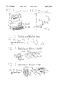
FIG. 1 is a diagrammatic perspective view that shows a computer system having a central processing unit and disk memory, keyboard, mouse, and monitor, on which is displayed a 3-dimensional geometric model as a wireframe.
FIGS. 2 to 5 are graphical diagrams that illustrate point objects: FIG. 2, Absolute Point and Relative Point; FIG. 3, Absolute Bead and Relative Bead; FIG. 4, Absolute Magnet and Relative Magnet; FIG. 5, Absolute Ring and Relative Ring.
FIGS. 6 to 10 are graphical diagrams that illustrate curve objects: FIG. 6, Line and Arc curves; FIG. 7, B-Spline Curve; FIG. 8, C-Spline Curve; FIG. 9, Sub-curve; FIG. 10, Relative Curve.
FIGS. 11 to 18 are graphical diagrams that illustrate surface objects: FIG. 11, Ruled Surface; FIG. 12, Translation Surface; FIG. 13, Revolution Surface; FIG. 14, Blended Surface; FIG. 15, C-Lofted Surface; FIG. 16, B-spline Surface; FIG. 17, Sub-surface; FIG. 18, Relative Surface.
FIGS. 19 to 24 are graphical diagrams that illustrate snake objects: FIG. 19, Line Snake; FIG. 20, Arc Snake; FIG. 21, B-spline Snake; FIG. 22, C-spline Snake; FIG. 23, Sub-snake; FIG. 24, Relative Snake.
FIG. 25 is an example of the dependency digraph for a simple model.
FIG. 26 is a block diagram that illustrates an example organization of program modules which implements the present invention. FIG. 27 is a graphical diagram that shows an example application.
FIGS. 28-32 are flow chart diagrams that illustrate example sequences of process steps for creating and modifying a three dimensional geometric model according to the invention.
FIGS. 33 and 34 are flow chart diagrams that illustrate the organization of Point and Curve primary program modules and an example strategy for Point object and Curve object evaluations using a lookup table.
FIG. 35 is a graphical diagram of a parametric solid object.
DETAILED DESCRIPTION OF THE PREFERRED EMBODIMENT
One preferred embodiment of the invention is a computer program operating on a suitable computer system such as an IBM-PC compatible or engineering workstation with a high-resolution color graphics display. The input device can be either a keyboard or a mouse. The graphics display is used primarily to display wireframe images of the model in perspective and/or orthogonal views. Controls are provided so the user can freely rotate, zoom or pan to select appropriate views. Alternative screen windows can show the u, v parameter space of a surface; outline-form listings of objects and their dependencies; and the text form of the logical model. FIG. 1 shows a computer system having a central processing unit and disk memory 11, keyboard 12, mouse 13, and monitor 14, on which is displayed a 3-dimensional object as a wireframe 15.
In the graphics display, a visible point object is displayed as a small circle. A visible line, curve, or snake object is represented as a polyline with a user-selectable number of subdivisions. A visible surface object is displayed as a mesh of parameter lines having a user-selectable number of subdivisions in each parameter direction. With more advanced graphic display hardware, surface objects may be rendered as solids with hidden lines and surfaces removed.
All objects have a color attribute; this can select one color from a palette of 16. All objects have a visibility attribute; this is a 16-bit integer in which the bits have different significance for different classes of entities, as follows:
points:
bit 1: point is visible
curves, snakes:
bit 1: polyline is visible
bit 2: polygon is visible
bit 3: tick-marks displayed at uniform parameter intervals
surfaces:
bit 1: parameter lines in u-direction are visible
bit 2: parameter lines in v-direction are visible
bit 4: boundary is visible
The following is a list of entities supported in the preferred embodiment:
Point Class
Absolute Point (AbsPoint): x, y, z
x, y, z are the absolute coordinates of the point.
Relative Point (RelPoint): point, dx, dy, dz
dx, dy, dz are the coordinate offsets from `point`FIG. 2 shows an Absolute Point 21 and a Relative Point 22 located in a Cartesian coordinate system.
Absolute Bead (AbsBead): curve, t
t is an absolute parameter value on `curve`
Relative Bead (RelBead): bead, dt
dt is the parameter offset from `bead`FIG. 3 shows a curve 31 in 3-space mapped from a 1-D parameter space 32, an Absolute Bead 33, and a Relative Bead located in both spaces.
Absolute Magnet (AbsMagnet): surface, u, v
u, v are the absolute parameters on `surface`
Relative Magnet (RelMagnet): magnet, u, v
du, dv are the parameter offsets from `magnet`FIG. 4 shows a surface 41 in 3-space mapped from a 2-D parameter space 42, an Absolute Magnet 43, and a Relative Magnet 44 located in both spaces.
Absolute Ring (AbsRing): snake, t
t is an absolute parameter value on `snake`
Relative Ring (RelRing): ring, dt
dt is a parameter offset from `ring`FIG. 5 shows a snake 51 in 3-space mapped from a 1-D parameter space 52 through a 2-D parameter space 53, and an Absolute Ring 54 and a Relative Ring 55 located in all three spaces.
Curve Class
(All curves are parameterized from 0. to 1.)
Line (Line): pointl, point2
The Line is a straight line from `point1` (x1) to `point2` (x2):
x(t)=(1-t) x.sub.1 +t x.sub.2
Arc (Arc): point1, point2, point3
The Arc is a circular arc interpolating the three points in sequence. FIG. 6 illustrates Line 61 and Arc 62 objects, dependent on 2 and 3 point objects 63 respectively.
D-spline curve (BCurve): type, point1, point2, . . . pointN
type gives the B-spline order: 1=linear, 2=quadratic, etc.
The named points are the vertices in sequence. ##EQU1## FIG. 7 illustrates a B-Spline Curve object 71, dependent on a multiplicity of point objects 72; and its 1-D parameter space 73.
C-spline curve (CCurve): point1, point2, . . . pointN
The named points are interpolated in sequence.
The curve is a parametric cubic spline with chord-length parameterization, knots at the data points, and not-a-knot end conditions. FIG. 8 illustrates a C-Spline Curve object 81, dependent on a multiplicity of point objects 82; and its 1-D parameter space 83.
Sub-curve (SubCurve): curve, bead1, bead2
The sub-curve y(t) is the portion of curve x(s) from `bead1` (parameter s1) to `bead2` (parameter s2):
y(t)=x[(1-t) s.sub.1 +t s.sub.2 ]
FIG. 9 illustrates a Sub-curve object 91, which is a portion of curve object 92 between two bead objects 93, 94; and the 1-D parameter spaces 95, 96 of the curve and the subcurve respectively.
Relative curve (CRelCurve): curve, point1, point2 The relative curve x(t) is formed from curve y(t) and the two points x1, x2 by the linear transformation:
x(t)=y(t)+(1-t) [x.sub.1 -y(0)]+t [x.sub.2 -y(1)]
FIG. 10 illustrates a Relative Curve object 101, dependent on a curve object 102 and two point objects 103, 104; and its 1-D parameter space 105.
Surface Class
(All surfaces are parameterized from 0 to 1 in both u and v directions)
Ruled surface (RuledSurf): curve1, curve2 The surface is formed from the two curves y(t), z(t) by linear interpolation:
x(u,v)=(1-v) y(u)+v z(u)
FIG. 11 illustrates a Ruled Surface object 111, dependent on two curve objects 112, 113; and its 2-D parameter space 114.
Translation surface (TranSurf): curve1, curve2
The surface is formed from the two curves y(t), z(t) by addition:
x(u,v)=y(u)+z(v)-z(0)
FIG. 12 illustrates a Translation Surface object 121, dependent on two curve objects 122, 123, and its 2-D parameter space 124.
Revolution surface (RevSurf): curve, point1, point2, angle1, angle2
The surface point at u, v is constructed by taking a point y(v) from `curve`, then rotating it through an angle θ=(1-u) θ1 +u θ2 about the axis line from `point1` to `point2`. FIG. 13 illustrates a Revolution Surface object 131, dependent on one curve object 132 and two point objects 133, 134 which define an axis 135; and its 2-D parameter space 136.
Blended surface (BlendSurf): curve1, curve2, curve3, curve4
The surface is a bilinear Coons patch constructed from the four curves. If the four curves are oriented end-to-end as in FIG. 14, the equation for locating a surface point is: ##EQU2## FIG. 14 illustrates a Blended Surface object 141, dependent on four curve objects 142, 143, 144, 145; and its 2-D parameter space 146.
C-lofted surface (CLoftSurf): curve1, curve2, . . . curveN
A surface point x(u,v) is obtained in three stages: (1) from each curve i take the point xi (u); (2) form the C-spline curve which interpolates the xi (u) in sequence; (3) evaluate the C-spline at parameter v.
FIG. 15 illustrates a C-Lofted Surface object 151, consisting of an infinitude of C-splines 152 interpolating several curve objects 153.
B-spline tensor-product surface (BSurf): typeU, typeV, N, M, pointll, point12, . . . pointNM
typeU, typeV give the B-spline orders for u and v directions. N, M are numbers of vertices in u, v directions. point11, point12, . . . pointNM are a rectangular net of control points. ##EQU3##
FIG. 16 illustrates a B-spline Surface object 161, dependent on an array of point objects 162; and its 2-D parameter space 163.
Sub-surface (SubSurf): surface, snake1, snake2, snake3, snake4
The sub-surface is a portion of surface Y(P,q) bounded by the four snakes w1, w2, w3, w4 in end-to-end sequence. ##EQU4##
FIG. 17 illustrates a Sub-surface object 171, dependent on a surface object 172, four snake objects 173, 174, 175, 176; and the 2- D parameter spaces 177, 178 of the surface and the sub-surface respectively.
Relative surface (RelSurf): surface, point1, point2, point3, point4
The relative surface x(u,v) is formed from surface y(u,v) and the four corner points x1, x2, x3, x4 by the bilinear transformation: ##EQU5##
FIG. 18 illustrates a Relative Surface object 181, dependent on a surface object 182 and four point objects 183, 184, 185, 186; and its 2-D parameter space 187.
Snake class
(All snakes are parameterized from 0 to 1. A snake is evaluated by first locating a point w={u,v} in the parameter space of the surface, then evaluating the surface with those parameter values.)
Line snake (LineSnake): magnet1, magnet2
The LineSnake is a straight line in u, v parameter space from `magnet1` (w1={u1, v1}) to `magnet2` (w2={u2, v2}):
w(t)=(1-t) w1+t w2
FIG. 19 illustrates a Line Snake object 191, dependent on a surface object 192 and two magnet objects 193, 194; and the 1-D parameter space 195 of the snake; and the 2-D parameter space 196 of the surface.
Arc snake (ArcSnake): magnet1, magnet2, magnet3
The ArcSnake is a circular arc in u, v parameter space interpolating the three magnets. FIG. 20 illustrates an Arc Snake object 201, dependent on a surface object 202 and three magnet objects 203, 204, 205; and the 1-D parameter space 206 of the snake; and the 2-D parameter space 207 of the surface.
B-spline snake (BSnake): type, magnet1, magnet2, . . . magnetN
type gives the B-spline order: 1=linear, 2=quadratic, etc. The named magnets are the vertices in sequence. ##EQU6##
FIG. 21 illustrates a B-spline Snake object 211, dependent on a surface object 212 and multiple magnet objects 213; and the 1-D parameter space 214 of the snake; and the 2-D parameter space 215 of the surface.
C-spline snake (CSnake): magnet1, magnet2, . . . magnetN
The named magnets are interpolated in sequence.
The snake is a parametric cubic spline in the u, v parameter space with chord-length parameterization, knots at the data points, and not-a-knot end conditions.
FIG. 22 illustrates a C-spline Snake object 221, dependent on a surface object 222 and multiple magnet objects 223; and the 1-D parameter space 224 of the snake; and the 2-D parameter space 225 of the surface.
Sub-snake (SubSnake): snake, ring1, ring2
The sub-snake w(t) is the portion of `snake` p(s) from `ring1` (parameter s1) to `ring2` (parameter s2):
w(t)=p[(1-t) s.sub.1 +t s.sub.2 ]
FIG. 23 illustrates a Sub-snake object 231, dependent on a surface object 232, a snake object 233, and two ring objects 234, 235; and the 1- D parameter spaces 236, 237 of the snake and sub-snake respectively; and the 2-D parameter space 238 of the surface.
Relative snake (RelSnake): snake, magnet1, magnet2
The relative snake w(t) is formed from `snake` p(t) and the two magnets m1, m2 by the linear transformation:
w(t)=p(t)+(1-t) [m.sub.1 -p(0)]+t [m.sub.2 -p(1)]
FIG. 24 illustrates a Relative Snake object 241, dependent on a surface object 242, a snake object 243, and two magnet objects 244, 245; and the 1-D parameter space 246 of the relative snake; and the 2-D parameter space 247 of the surface.
TABLE III is a summary of the data items required to actualize each of the entities into an object.
Further entities which may be added to those described in detail above include the following:
Infinite (non-parametric) Planes specified in several ways, e.g. at specified x, y, or z coordinates; through three point objects; normal to a curve at a specified bead; tangent to a surface at a specified magnet;
Contour objects formed by intersection of surfaces with families of non-parametric planes, cylinders or spheres;
Mirrored Points, Curves, and Surfaces formed by reflecting any object of the specified class through a Plane, Line or Point object;
Projected Points, Curves, and Surfaces formed by projection of any object of the specified class onto a Plane or Line object;
Rotated Points, Curves and Surfaces formed by rotation of any object of the specified class about an axis Line object through a specified angle;
Foil Curves, Snakes and Foil-Lofted Surfaces utilizing standard airfoil curves;
Helix, conic, Catenary and Spiral curves;
NURBS Curves, Snakes and Surfaces;
PolyCurves, made by joining two or more specified curve objects end-to-end and reparameterizing from 0 to 1;
PolySnakes, made by joining two or more specified snake objects end-to-end and reparameterizing from 0 to 1;
Developable Surfaces, specified by two edge curves;
Fillet Surface, specified by two or more snakes on two different surfaces;
Swept Surfaces, formed by sweeping a parametrically varied cross-section curve along a specified curve object;
Projected Snake, formed by projecting a specified curve object onto a specified surface object;
Contour Bead, a Point object located at the intersection of a specified Curve object with a specified Plane object;
Contour Ring, a Point object located at the intersection of a specified Snake object with a specified Plane object;
Contour Snake, a Snake object located at the intersection of a specified Surface object with a specified Plane object;
BeadMagnet, a Point object at the intersection of a specified Curve object with a specified Surface object, and. serving as a bead on the curve and as a magnet on the surface;
RingMagnet, a Point object at the intersection of a specified Snake object with a specified Surface object, and serving as a ring on the snake and as a magnet on the surface;
BiSnake, a one-dimensional object located at the intersection of two specified Surface objects, and serving as a snake on either surface;
BiRing, a Point object located at the intersection of two specified Snake objects, and serving as a ring on either snake;
Parametric Solids such as Ruled Solid, Translation Solid, Revolution Solid, Blended Solid, B-spline Solid, C-lofted Solid, and NURBS Solid. FIG. 35 illustrates a Revolution Solid 300 formed by revolving a specified Surface object 302 through a specified angle θ, about a specified axis Line Y.
Logical models are stored as files in disk memory, in a text format similar to that previously outlined, but with some additional numerical parameters specifying polyline subdivisions for display. Each object is represented by a single text record beginning with the entity keyword indicated in parentheses in each of the above entity definitions. The keyword is followed by the object name, and color and visibility indices. Any curve or snake object will then have an integer telling the number of subdivisions desired for the polyline representing it in the display; any surface object will have two integers specifying the number of subdivisions in the u and v directions for the polyline mesh representing it in the display. Beyond this point, the required data for most entities is different, as indicated in the entity definitions above. The text file is terminated by the keyword "End". Remarks can be included in the text file by use of the keyword "Rem".
Internal to the program, objects are referenced by serial numbers corresponding to their sequence in the input data file, or sequence of creation. Requiring that all references be to previously defined objects is a simple way to eliminate the possibility of circular dependencies (digraph cycles). The organization of internal storage of the logical model includes a linked-list data structure representing the dependency digraph, to be used during updates of the absolute model. FIG. 25 is a digraph representing the dependencies in the "line A-line B" example developed in a previous section. The nodes 251 represent objects, and the edges 252 represent their dependencies.
The program has user-controlled capabilities for reading and writing logical-model data files in the appropriate text format, and for detecting and reporting errors and inconsistencies in a data file during read operations. The program can also read and display, simultaneous with displaying a model, one or more files representing 3-dimensional wireframes. The program can also write a 3-dimensional wireframe file of the absolute model currently displayed, or a 2-dimensional wireframe file of the current view.
Interactive capabilities are provided for creating, editing and deleting objects. Limited capabilities are provided for appropriate transmutations of objects to a different entity type; for example, any point object can be transmuted into an absolute point. In all these activities the program performs consistency checks and enforces rules ensuring the integrity of the digraph data structure. For example: all required dependencies have to be fulfilled before a newly created object is accepted into the logical model; an object cannot be deleted until all of its dependents have been deleted; circular dependencies are not permitted.
FIG. 26 shows an example organization of program modules which implements the invention. Each box 263, 264 represents a subroutine; each arrow 262 represents a subroutine call, with the arrow directed from the calling module to the called module.
The three special modules ("primary modules", 263) labeled "Point", "Curve" and "Surface" are the interface to any application program requiring absolute geometric information from the model. These have input and output arguments as follows:
Point--in: name (or index) of a point object
out: absolute coordinates x, y, z
Curve--in: name (or index) of a curve object list of t parameter values
out: list of point coordinates x, y, z
Surface--in: name (or index) of a surface object list of u parameter values list of v parameter values (or, list of u, v parameter pairs)
out: array of point coordinates x, y, z
(An input list of parameter values may have only a single entry, if only one point needs to be evaluated.)
The other modules ("secondary modules", 264) illustrated are not intended to be called from an application, being called only by the primary modules, as indicated by arrows, or in some cases by other secondary modules. These have input and output arguments as follows:
Bead--in: name (or index) of a bead object
out: identity of supporting curve t parameter value
Magnet--in: name (or index) of a magnet or ring object
out: identity of supporting surface u, v parameter pair
Ring--in: name (or index) of a ring object
out: identity of supporting snake t parameter value
Snake--in: name (or index) of a snake object list of t parameter values
out: identity of supporting surface list of u, v parameter pairs
The remaining secondary modules have the same arguments as the primary modules that call them.
Module "Point" determines what kind of point object it is evaluating and branches to the appropriate secondary routine, as indicated. Depending on the entity, "Point" may have to then call "Curve", "Snake", and/or "Surface" to complete its job. For example, if the object is any type of bead, "Point" calls "Bead", which returns the identity of the curve to which the bead belongs, and a single t parameter value. "Point" must then call "Curve" with this curve and parameter value, receiving back the x, y, z coordinates of the particular point occupied by the bead. Similarly, "Magnet" returns the identity of the surface which supports the magnet, and a u, v parameter pair. "Point" must then call "Surface" with this information, receiving back x, y, z coordinates. In the case of a ring, "Point" first calls "Ring", identifying the supporting snake and receiving a t parameter value; then it calls "Snake" with t and receives back identity of the surface and a u, v parameter pair; then it calls "Surface" with u, v and receives back x, y, z coordinates.
"Magnet" can be called with any object that can serve as a magnet, i.e. with a magnet or ring. If the object is a ring, "Magnet" first calls "Ring" to identify the snake, and a t parameter value; then calls "Snake" to identify the supporting surface and receive a u, v parameter pair.
"Curve", "Snake" and "Surface" are primarily branches to their constituent secondary routines. Since any point object can serve as a curve, "Curve" needs to be able to call "Point". Similarly, since any magnet or ring can serve as a snake, "Snake" needs to be able to call "Magnet". Also, since any snake object can serve as a curve, "Curve" must accept the index or name of a snake, call "Snake" to identify the supporting surface and receive back a list of u, v parameter pairs; then call "Surface" to evaluate x, y, z coordinates.
"Line" and "Line Snake" routines share a common "Line math" routine; similarly, the other curves and snakes share common math routines. The math routines are able to operate with either 2-D data (when called by a snake routine) or 3-D data (when called by a curve routine). It is obvious in FIG. 26 how easily a new parametric curve, snake, or surface entity can be added to the system; it requires only the addition of one secondary module implementing the new entity, and a small modification of one primary module, adding a branch to the new secondary module.
Some recursive calls are apparent as cycles in FIG. 26. The most obvious of these are the way "Magnet", "Bead" and "Ring" call themselves when they are evaluating a Relative Magnet, Bead or Ring. For another example, to locate a Relative Point, the program first needs to locate the basis point, no matter what kind of point object the basis point is. Thus, "Relative Point" must be able to call "Point". Similarly, "SubCurve" and "Relative Curve" must be able to call "Curve"; "SubSnake" and "Relative Snake" must be able to call "Snake"; and "SubSurface" and "Relative Surface" must be able to call "Surface".
Other potentially recursive calls to the primary routines are needed, which are not indicated by arrows in FIG. 26, because the arrows showing all such possibilities would be too numerous. For example, "Line", "Arc", "B-Curve" and "C-Curve" all need to evaluate their supporting points, by a series of calls to "Point". "Line Snake", "Arc Snake", "B-Snake" and "C-Snake" need to evaluate the u, v parameters of each of their supporting magnet objects, by a series of calls to "Magnet". The several surface routines need to evaluate various point, curve or snake objects, according to their individual constitutions; these are all done through calls to the primary modules.
Further levels of recursion occur when, for example, one curve supporting the surface being evaluated is a snake on another surface. In this case the sequence of calls passes through "Surface" twice. It is easy to think up cases with arbitrarily long chains of dependency. All such recursire possibilities are accommodated by the program structure indicated in FIG. 26. Without recursion, the program complexity and size would grow extremely rapidly with the allowable depth of dependency; with recursion, only stack space is required to indefinitely extend the permitted depth of dependency.
EXAMPLE APPLICATION OF THE PREFERRED EMBODIMENT
Table 1 is a text representation of an example logical model utilizing a variety of point, curve and snake objects, and six interconnected surface objects of various types, as defined and outlined above. FIG. 27 is a wireframe representation of the resulting absolute model. The example comprises hull, deck and cabin surfaces for a 30-foot sailing yacht design.
The example model has six surface objects: `hull` 271 and `deck` 272 are C-lofted surfaces; `cabin-- fwd` 273, `cabin-- side` 274, and `cabin-- aft` 275 are ruled surfaces; and `cabin-- top` 276 is a blended surface. The surfaces all have visibility 2, which causes only the parameter lines in the v-direction to be displayed. Eleven transverse sections 277 through the model are also displayed for purposes of visualizing the shapes.
`hull` is a C-lofted surface with three B-spline master curves `MCA`, `MCB`, `MCC`, each having four absolute points as vertices. `deck` also has three master curves; the first is the single point `MCAV1`, the other two are 3-vertex B-spline curves `deck-- beam` and `transom`. The join 278 between `hull` and `deck` is accurate and durable because the C-splines at the adjoining edges on each surface use the same data points, viz `MCAV1`, `MCBV1`, `MCCV1`, and therefore are identical curves.
The three ruled surfaces `cabin-- fwd`, `cabin-- side`, `cabin-- aft` are constructed in a similar fashion to one another; each uses a snake on `deck` as one edge, providing an accurate and durable join 279 to the `deck` surface, and a relative curve dependent on that snake as the second (upper) edge. The three snakes on `deck` join each other accurately and durably because they share common endpoint data, viz. magnets `dm3` and `dm5`. The three relative curves `top-- fwd`, `top-- side`, `top-- aft` also join each other accurately and durably because they are constructed using common end points, viz. relative points `rp3` and `rp5`. `cabin-- side` joins the other two surfaces accurately because its end rulings are the lines `dm3`-`rp3` and `dm5`-`rp5`, which are identical to end rulings on the adjoining surfaces.
The blended surface `cabin-- top` joins the three ruled surfaces accurately because it uses their upper edge curves `top-- fwd`, `top-- side`, `top-- aft` as data. Its fourth side is a three-vertex C-spline `top-- ctr`, which lies accurately in the centerplane because each of its vertices has a zero y coordinate.
The example model as now defined can easily be transformed into an extremely wide variety of alternative shapes by changing the coordinates of absolute points, the offsets of relative points, and the parameters of magnets. An example modification which affects all six surfaces is to increase the y coordinate of `MCBV1`. Following any such change, the connectivity and relative positioning of the several surfaces is automatically preserved as the absolute model is updated.
FIGS. 28-32 illustrate possible sequences of process steps for creating and modifying a three-dimensional geometric model in accordance with the invention. In these flowcharts, solid arrows represent the temporal sequence of execution, while dashed arrows represent the flow of data between program modules and computer memory. The memory elements, depicted as cylinders, can be any form of computer memory including but not limited to disk files and random-access memory (RAM).
FIG. 28 shows a possible sequence of steps for creating a model. The "Create object" step is elaborated in FIG. 29. An object is created by first selecting an entity, then filling in the data fields required to actualize that particular entity. All entities require an object name, color, and visibility. Curves and snakes require specification of t-divisions; surfaces require specification of u- and v-divisions. Each object requires further data, its quantity, character and sequence depending on the entity definition. To obtain the specification for this variable object data, the program accesses stored data coding the entity definitions. The data entered during the "Create object" step may come from user interaction, or may be read in from a data file.
In FIG. 28, following the "Create object" step, the resulting logical object data is stored in memory. In the next step, a wireframe representation of the object is made and stored in memory. During this "Make object wireframe" step, calls will be made to Point, Curve, or Surface routines as required by the class of entity. Next, the object wireframe is displayed; this will require a projection transformation if the display device is two-dimensional, as is usual.
While further objects need to be created, the program loops back to the "Create object" step. When the model is complete, both logical and absolute model data may be accessed to create output files, or for other evaluation purposes.
FIG. 30 illustrates a possible sequence of process steps for modifying a model in accordance with the invention. Editing can take place following completion of the steps of FIG. 28, or editing and creation steps may be interspersed. The first step in editing a model is to edit the logical data of a particular selected object. In this process the existing logical data for the object may be offered as defaults. The editing process is controlled by reference to the stored data which codes entity definitions and specifies what kind of data the entity requires. When the appropriate fields of object data have been altered, the logical object data representing this object in memory is updated. Making use of the stored dependency digraph, an "update list" is compiled of all objects affected by the change, i.e., first-generation dependents of the altered object, their dependents, etc. This list is headed by the altered object, is purged of duplicates, and is ordered so as to assure that all affected objects are updated in appropriate sequence, i.e. supports before dependents in every case.
The program next cycles automatically through the update list, creating an updated wireframe for each affected object. The "Update object wireframe" step during editing is essentially the same as the "Make object wireframe" step in FIG. 28, except that wireframe data of other objects may have to be moved if the new object wireframe is of different size from the existing one. When all affected objects have been processed, the entire model is up-to-date, and may be displayed, evaluated, and further modified.
LOOKUP TABLE DATA STRUCTURES AND PROCEDURES AS AN ALTERNATIVE TO DIRECT RECURSIVE EVALUATION
Lookup tables may be advantageously employed to improve the response of the program during initial evaluation and subsequent modification of a model. A portion of computer memory or disk memory (the "lookup table") is organized suitably for the storage of absolute object data. As each object is evaluated in sequence, its absolute coordinates and/or parameter values are recorded in the table. When and if this object is referenced during evaluation of later objects, the tabulated values can be used (usually by means of interpolation), rather than following the recursive evaluation procedure.
The lookup table is envisaged as being organized into "records", each record consisting of a variable number of real numbers, depending on the entity. A lookup table record will always contain x, y, and z values. For a bead, the record can additionally include t; for a magnet or snake, each record can include u and v; for a ring, each record can include t, u, and v.
A point object requires only a single record. A curve or snake object requires a sequence of records representing points distributed along the object. A surface object requires a sequence of records representing points distributed over the object in some orderly specified fashion.
For point objects, which require only one record and no interpolation, there is no loss of accuracy in using the lookup table.
For curve, snake, and surface objects, some loss of accuracy usually will result from the substitution of lookup table interpolation in place of direct recursive evaluation. This error depends in a complicated way on the number and distribution of the tabulated data points; the curvatures and higher derivatives of the tabulated object; the method of interpolation; and the specific parameter values for which the tabulated object needs to be evaluated. Because the interpolation error is difficult to predict or to bound, and because it accumulates from object to object as evaluation proceeds, the accuracy of the resulting absolute model is uncertain. However, it is known that even with the simplest interpolation scheme (linear interpolation for curves and snakes, bilinear interpolation for surfaces) and relatively coarse tabulations (such as 16 to 32 uniform divisions) the resulting accuracy is usually entirely adequate for visual evaluation and interactive editing. When greater accuracy is required, for example for N/C machining data, more accurate interpolation schemes can be employed; tabulated objects can be more finely subdivided; or direct recursive evaluation can be invoked.
The tabulated data need not be limited to points on the tabulated object. In a spline- or NURBS-based program, the tabulated data could be control points. If an interpolation scheme requiring derivative information is to be employed, the tabulated data would include first or higher derivative data.
Using lookup table interpolation, program structure can be substantially the same as FIG. 26, with one significant modification of each of the four primary modules. Each primary module will begin by accessing the index information in the table data and ascertaining whether the current object has been tabulated, and whether its tabulated data is up-to-date. If the table index data indicates that an up-to-date tabulation exists, the primary routine will branch to an appropriate interpolation routine (or, in the case of Point, will simply read the tabulated data); otherwise, it will follow the usual recursive path. In the second case it is apparent that the recursion will never be more than one level deep, since all supporting objects will have already been tabulated.
FIGS. 33 and 34 illustrate the organization of Point and Curve primary modules, respectively, for object evaluations using the lookup table. In all cases, if the object is found to be tabulated, then the usual recursive calls are avoided. The Curve primary module contains a loop which cycles through the evaluation of all requested points before exiting. Snake and Surface primary modules may be organized similar to Curve, except that surfaces require bidirectional interpolation.
FIGS. 31 and 32 illustrate possible sequences of steps for utilizing lookup tables during model creation and editing respectively. The essential differences from FIGS. 28 and 30 are the presence of the lookup table data structures, and the addition of a "Make object tabulation" or "Update object tabulation" step which stores data in these structures, using calls to primary modules to generate table data. Not apparent in these flowcharts is the advantage that the primary modules can use interpolation rather than regenerating object data recursively. The "Make object wireframe" and "Update object wireframe" steps utilize data from the lookup table. The "Extract geometric data" step also can access data from the lookup table when appropriate.
Parametric solids are disclosed in the Summary of the Invention above and an example is illustrated in FIG. 35. In this example, a Revolution Solid 300 is formed by moving a specified Surface object 302 through a specified angle θ about the axis Line Y.
TABLE II is a program listing of a program entitled RGS.BAS, written in the computer language QuickBasic 4.5, which implements the disclosed method of computer aided design of geometric models, including automatic updating of the entire model following a change in a supporting geometric object. RGS.BAS is organized in accordance with the block diagram of FIG. 26. Each block in the diagram is implemented as a separate QuickBasic subroutine. Each arrow in the diagram of FIG. 26 is identifiable as a CALL Statement in the program. To illustrate a useful application of the primary routines, RGS.BAS includes routines that compute a 3-dimensional wireframe such as the ones illustrated in FIGS. 2-25 and 27. The routines that compute the wireframe call the primary routines Point, Curve, and Surface in order to receive all required geometric information about the absolute model.
RGS.BAS reads lines from an ASCII text file containing the description of an arbitrary logical model as disclosed and defined in this patent specification. The example set forth in TABLE 1 of this specification is a valid input file. Each geometric object is specified with a geometric object record of one or more lines in the input file, terminated by a semicolon. The order of data in a geometric object record is: entity keyword; object name; color; visibility; and variable entity data. Data items in a geometric object record are separated by one or more spaces. Variable length lists of supporting geometric object names are enclosed in braces{}. Remarks are permitted using the keyword "Rem". The input file is terminated by the keyword "End".
RGS.BAS reads the input file and stores an internal representation of the logical model in arrays, including a representation of the directed graph data structure of multiple dependencies. It computes from this stored internal representation a 3-dimensional wireframe representation of the implied absolute model, using recursion as required to support multiple levels of dependency. RGS supports by computer implemented steps all 28 of the geometric entities disclosed in this patent specification.
RGS.BAS outputs 3-dimensional wireframe data to an ASCII text file in a prescribed format (3DA). The output file can easily be translated to a variety of CAD formats including 3-dimensional DXF files for AutoCAD. It can be directly displayed in 3 dimensions with off-the-shelf software such as AeroHydro's C3D.
RGS.BAS provides user interaction allowing the user to alter any of the numerical values in any point object. Using the stored digraph data structure, RGS.BAS selectively updates all geometric objects affected by the change, and writes a new wireframe file for the updated absolute model.
              TABLE 1
______________________________________
Text representation of logical model for the example
application.
(Entity keyword; name; color; visibility; variable entity
data)
Rem 3×4 cloft hull with deck and cabin for patent example
AbsPoint MCAV1 14 1 0.00 0.00 3.60;
AbsPoint MCAV2 14 1 1.00 0.00 1.41;
AbsPoint MCAV3 14 1 2.50 0.00 -0.84;
AbsPoint MCAV4 14 1 3.00 0.00 -0.90;
BCurve MCA 12 1 20 2
 { MCAV1 MCAV2 MCAV3 MCAV4 };
AbsPoint MCBV1 14 1 15.00 5.84 2.64;
AbsPoint MCBV2 14 1 15.00 6.00 0.54;
AbsPoint MCBV3 14 1 15.00 3.90 -1.20;
AbsPoint MCBV4 14 1 15.00 0.00 -1.44;
BCurve MCB 12 1 20 2
 { MCBV1 MCBV2 MCBV3 MCBV4 };
AbsPoint MCCV1 14 1 30.00 3.50 2.76;
AbsPoint MCCV2 14 1 30.90 3.50 1.41;
AbsPoint MCCV3 14 1 31.70 2.50 0.22;
AbsPoint MCCV4 14 1 31.70 0.00 0.22;
BCurve MCC 12 1 20 2
 { MCCV1 MCCV2 MCCV3 MCCV4 };
CLoftSurf hull 10 2 20 30 0 1 MCA MCB MCC
AbsPoint transom0 14 1 29.80 0.00 3.00;
AbsPoint transom1 14 1 29.80 1.75 3.00;
BCurve transom 10 1 10 2
 { MCCV1 transom1 transom0 };
AbsPoint deck.sub.-- ctr 14 1 15.00 0.00 3.45;
AbsPoint deck.sub.-- mid 14 1 15.00 2.70 3.45;
BCurve deck.sub.-- beam 10 1 10 2
 { MCBVL deck.sub.-- mid deck.sub.-- ctr };
CLoftSurf deck 7 2 8 10
 { MCAV1 deck.sub.-- beam transom };
AbsMagnet dm1 11 1 deck 1.00 0.27;
AbsMagnet dm2 11 1 deck 0.63 0.27;
AbsMagnet dm3 11 1 deck 0.35 0.30;
AbsMagnet dm4 11 1 deck 0.20 0.50;
AbsMagnet dm5 11 1 deck 0.20 0.70;
AbsMagnet dm6 11 1 deck 1.00 0.70;
BSnake footprint.sub.-- fwd 11 1 10 2
 { dm1 dm2 dm3 };
BSnake footprint.sub.-- side 11 1 20 2
 { dm3 dm4 dm5 };
LineSnake footprint.sub.-- aft 11 1 10 dm5 dm6;
RelPoint rp1 11 1 dm1 2.00 0.00 1.30;
RelPoint rp3 11 1 dm3 2.00 0.00 1.10;
RelPoint rp5 11 1 dm5 -0.20 -0.50 1.40;
RelPoint rp6 11 1 dm6 -0.30 0.00 1.80;
RelPoint rp7 11 1 deck.sub.-- ctr 0.00 0.00 1.65;
RelCurve top.sub.-- fwd 11 1 10 footprint.sub.-- fwd rp1 rp3;
RelCurve top.sub.-- side 11 1 20 footprint.sub.-- side rp3 rp5;
RelCurve top.sub.-- aft 11 1 10 footprint.sub.-- aft rp5 rp6;
RuledSurf cabin.sub.-- fwd 11 2 10 1
 footprint.sub.-- fwd top.sub.-- fwd ;
RuledSurf cabin.sub.-- side 11 2 20 1
 footprint.sub.-- side top.sub.-- side ;
RuledSurf cabin.sub.-- aft 11 2 10 1
 footprint.sub.-- aft top.sub.-- aft ;
CCurve top.sub.-- ctr 11 1 10 2
 { rp1 rp7 rp6 };
BlendSurf cabin.sub.-- top 14 2 4 5
 { top.sub.-- fwd top.sub.-- side top.sub.-- aft top.sub.-- ctr };
______________________________________
End
 ##SPC1##
                                  TABLE III
__________________________________________________________________________
Summary of entity definitions.
Entity
      Name
          Color
              Visibility
                   t-divisions
                         u, v-divisions
                                Variable data
__________________________________________________________________________
AbsPoint
      x   x   x                 x, y, z
RelPoint
      x   x   x                 dx, dy, dz
AbsBead
      x   x   x                 curve, t
RelBead
      x   x   x                 bead, dt
AbsMagnet
      x   x   x                 surface, u, v
RelMagnet
      x   x   x                 magnet, du, dv
AbsRing
      x   x   x                 snake, t
RelRing
      x   x   x                 ring, dt
Line  x   x   x    x            point1, point2
Arc   x   x   x    x            point1, point2, points
BCurve
      x   x   x    x            type, { point }
CCurve
      x   x   x    x            { point }
SubCurve
      x   x   x    x            curve*, bead1, bead2
RelCurve
      x   x   x    x            curve, point1, point2
LineSnake
      x   x   x    x            magnet1, magnet2
ArcSnake
      x   x   x    x            magnet1, magnet2, magnet3
BSnake
      x   x   x    x            type, { magnet }
CSnake
      x   x   x    x            { magnet }
SubSnake
      x   x   x    x            snake*, fing1, ring2
RelSnake
      x   x   x    x            snake, magnet1, magnet2
RuledSurf
      x   x   x          x      curve1, curve2
TranSurf
      x   x   x          x      curve1, curve2
RevSurf
      x   x   x          x      curve, point1, point2, angle1, angle2
BlendSurf
      x   x   x          x      curve1, curve2, curve3, curve4
CLoftSurf
      x   x   x          x      { curve }
BSurf x   x   x          x      typeu, typev, N, M, { point }
SubSurf
      x   x   x          x      surface*, snake1, snake2, snake3, snake4
RelSurf
      x   x   x          x      surface, point1, point2, point3,
__________________________________________________________________________
                                point4
 Key: x data item is required
 *data item is redundant and could be omitted
 { . . . }variablelength list of objects of specified class