US5628126A - Revolving drum drying apparatus and method - Google Patents
Revolving drum drying apparatus and method Download PDFInfo
- Publication number
- US5628126A US5628126A US07/956,006 US95600694A US5628126A US 5628126 A US5628126 A US 5628126A US 95600694 A US95600694 A US 95600694A US 5628126 A US5628126 A US 5628126A
- Authority
- US
- United States
- Prior art keywords
- drum
- spiral
- pathways
- charge
- pathway
- Prior art date
- Legal status (The legal status is an assumption and is not a legal conclusion. Google has not performed a legal analysis and makes no representation as to the accuracy of the status listed.)
- Expired - Fee Related
Links
Images


Classifications
-
- F—MECHANICAL ENGINEERING; LIGHTING; HEATING; WEAPONS; BLASTING
- F26—DRYING
- F26B—DRYING SOLID MATERIALS OR OBJECTS BY REMOVING LIQUID THEREFROM
- F26B3/00—Drying solid materials or objects by processes involving the application of heat
- F26B3/18—Drying solid materials or objects by processes involving the application of heat by conduction, i.e. the heat is conveyed from the heat source, e.g. gas flame, to the materials or objects to be dried by direct contact
- F26B3/20—Drying solid materials or objects by processes involving the application of heat by conduction, i.e. the heat is conveyed from the heat source, e.g. gas flame, to the materials or objects to be dried by direct contact the heat source being a heated surface, e.g. a moving belt or conveyor
- F26B3/205—Drying solid materials or objects by processes involving the application of heat by conduction, i.e. the heat is conveyed from the heat source, e.g. gas flame, to the materials or objects to be dried by direct contact the heat source being a heated surface, e.g. a moving belt or conveyor the materials to be dried covering or being mixed with heated inert particles which may be recycled
-
- F—MECHANICAL ENGINEERING; LIGHTING; HEATING; WEAPONS; BLASTING
- F26—DRYING
- F26B—DRYING SOLID MATERIALS OR OBJECTS BY REMOVING LIQUID THEREFROM
- F26B11/00—Machines or apparatus for drying solid materials or objects with movement which is non-progressive
- F26B11/02—Machines or apparatus for drying solid materials or objects with movement which is non-progressive in moving drums or other mainly-closed receptacles
- F26B11/04—Machines or apparatus for drying solid materials or objects with movement which is non-progressive in moving drums or other mainly-closed receptacles rotating about a horizontal or slightly-inclined axis
- F26B11/0404—Machines or apparatus for drying solid materials or objects with movement which is non-progressive in moving drums or other mainly-closed receptacles rotating about a horizontal or slightly-inclined axis with internal subdivision of the drum, e.g. for subdividing or recycling the material to be dried
- F26B11/0413—Machines or apparatus for drying solid materials or objects with movement which is non-progressive in moving drums or other mainly-closed receptacles rotating about a horizontal or slightly-inclined axis with internal subdivision of the drum, e.g. for subdividing or recycling the material to be dried the subdivision consisting of concentric walls, e.g. multi-pass or recirculation systems; the subdivision consisting of spiral-shaped walls
Definitions
- This invention relates to a method of drying and to drying apparatus, in particular for drying wet materials in suspension, slurry or sludge form, for example sewage, industrial effluent and the like and also certain granular materials.
- the invention may also be applied to the cooling of materials.
- apparatus for drying wet materials comprises a drum mounted for revolution about a substantially horizontal axis, the drum having inlet means for material to be dried and outlet means for dried material, characterised in that the drum includes inner deflecting wall means defining a spiral pathway having a plurality of coils between the said inlet and outlet means with concentric inner and outer oppositely-handed spirals interconnected at their ends, the drum in use containing a charge of a solid heat exchange and pulverising medium in particulate form, the drum also including means to heat the said medium and means to vent vapours from within.
- the invention also includes a method for drying a wet material, the method comprising introducing the material into a revolvable drum having a substantially horizontal axis of revolution and containing a heated solid heat exchange and pulverising medium in particulate form and revolving the drum to mix the material and the heat exchange medium, the drum having inner deflecting wall means defining a spiral pathway having a plurality of coils with concentric inner and outer oppositely-handed spirals interconnected at their ends between the said inlet and outlet means, whereby the material and heat exchange medium are contained within the pathway and propelled axially of the drum while drying takes place, vapours being vented from within the drum, separating the dried and pulverised material from the heat exchange and pulverising medium and removing the said dried and pulverised material from the drum and recirculating the pulverising medium.
- the inner deflecting wall means is preferably fixed in relation to the drum outer wall whereby the inner surface of the said wall forms the floor of the pathway.
- the contents of the drum are caused by gravity, on rotation of the drum, to remain in the lower portion of each coil of the spiral pathway and thereby to traverse the length of the drum as rotation continues.
- the heat exchange and pulverising medium is preferably recirculated from the outlet to the inlet end of the drum with re-heating, following separation of the dried material, whereby the process operates continuously with each successive coil containing a discrete charge of heat exchange and pulverising medium and material undergoing drying.
- the interior of the drum comprises concentric inner and outer oppositely-handed spirals in communication at their ends, whereby on rotation of the drum the charge re-circulates through the spirals, material to be dried being introduced through the inlet means at one end and dried material being discharged through the outlet means at the other end, the material or a major part thereof making a single pass through one of the spirals, preferably the outer spiral.
- the heat exchange and pulverising medium is heated and re-heated during its return passage through the other one of the spirals, preferably the inner spiral, between the outlet and inlet means for dried material and for material to be dried, respectively.
- a discrete charge of medium is ejected from the end of the inner spiral at each complete revolution and falls under gravity to the beginning of the outer spiral, the ends of the respective spirals preferably being substantially in radial registration with each other to ensure clean uptake of each discrete charge by each respective coil of the outer spiral.
- the floor of the spiral pathway preferably gradually assumes a progressively smaller radius to lift the medium to transfer it from the outer to the inner spiral.
- the heating means for the heat exchange and pulverising medium may conveniently be a perforated pipe or tube mounted centrally within the drum and arranged to duct heated air therein. Exhaust air may be vented through the vent means together with vapours from the material undergoing drying. The heated air may itself directly assist in the drying operation.
- the heating means may comprise an annular perforate chamber between the inner and outer spirals, the heated air being preferably introduced at one end and at the lower region of the chamber, the other end being closed, the chamber including divider or baffle means, for example disposed radially, to confine the heated air to the lower part of the annular chamber from where it passes upwardly through the said medium.
- the heat exchange and pulverising medium preferably comprises balls formed from a material which is sufficiently hard to provide the required pulverising action and which has a heat capacity whereby it attains the desired temperature during initial heating or re-heating and retains an elevated temperature while losing heat to the material to be dried.
- a material which is sufficiently hard to provide the required pulverising action and which has a heat capacity whereby it attains the desired temperature during initial heating or re-heating and retains an elevated temperature while losing heat to the material to be dried.
- steel or stainless steel is a suitable material although ceramic materials such as steatite may also be used.
- the size of the balls and the amount of the charge is chosen according to the dimensions of the drum, the properties, for example viscosity, solids content, of the material to be dried, or other operating parameters.
- a charge of heat-exchange and pulverising medium is placed in the lower part of each successive coil of the spirals, whereby on rotation of the drum there is a continuous longitudinal progressive movement of medium in one direction along the drum, through the outer spiral, and in the reverse direction through the inner spiral.
- the medium tends to be drawn in the direction of rotation up the side of the drum until gravity causes it to slip back, whereby, particularly in the presence of material to be dried, the medium describes a constant churning or tumbling motion within the spiral path.
- this may be enhanced by providing vanes, paddles or other deflecting elements on the sides and/or the base of the spirals, to increase the agitation of the medium and hence the pulverising effect and to minimise build-up within the drum of caked sludge or other material to be dried.
- this object could be met by including straight-edged elements within the charge to act as scrapers.
- the medium naturally is constrained to accummulate together to a greater extent than in the larger-diameter outer spiral and this assists in efficient heat transfer from the heated air.
- the pitch of the spirals is preferably enlarged where the heat exchange and pulverising medium is transferred from the outer to the inner spiral, to prevent or minimize the build-up of an accumulation of said medium with resulting potential for blockage.
- the inlet and outlet means for the material to be dried which is preferably pre-macerated, and for the dried material respectively preferably comprise ports which are connected to the drum via revolvable glands.
- the inlet means may be constituted by a charging hopper and screw conveyor to an inlet duct which passes through an end wall of the drum via a revolvable gland, and the outlet means may be constituted by a perforate, mesh, or grid-like base to the spiral pathway at the other end of the drum, whereby dried material passes through into a covered receiving hopper for further processing in, for example, a briquette-forming device, and the heat exchange and pulverising medium is retained for re-circulation.
- the inlet means includes a gas seal and the cover of the receiving hopper surrounds the drum, to minimize undesirable losses of heating air.
- the receiving hopper may be subject to reduced pressure within, to assist removal of the dried material by suction.
- some of the air may be passed through the outer spiral, for example in contra-flow to the direction of movement of the material being dried, whereby moisture vapour in the dryer parts of the spiral are back-flushed to the wetter parts.
- the invention is suitable for use as part of a processing plant for sewage, household or industrial organic effluent containing grease and fatty substances, and the like, the plant also including filters, incinerators, furnaces for end-product material, cyclones, condensers and other treatment means as required. Combustion of the end-product material may provide heated air for the inventive process, thereby increasing its energy efficiency.
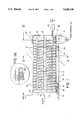
- FIG. 1 shows a cross-sectional side view of drying apparatus
- FIG. 1A is an enlarged fragmentary view inset taken at location "1A" of FIG. 1;
- FIG. 2 is a cross section along the line II--II of FIG. 1,
- FIG. 3 is a cross section along the line III--III of FIG. 1, excluding the receiving hopper and grid elements, and
- FIG. 4 is a fragmentary perspective representation of the FIG. 3 end of the apparatus with the end plate removed.
- the apparatus as shown consists of a drum 11 mounted horizontally on a base 12 via rollers 13 and 14. Rollers 13 are connected to a drive motor 15.
- a charge hopper (not shown) for material to be dried is connected to a pipe 16 which is in axial communication with the end wall 17 of the drum, for example via a gland; the pipe 16 contains a screw conveyor which, depending on the pitch, may act as a macerator.
- the outer circular wall is constituted by a series of grid elements 18 which communicate with the interior of a receiving hopper 19 which sealingly surrounds the screen material by means of a cover 20.
- the interior of the drum has deflecting walls which define a pathway constituted by an outer spiral 21 and an inner spiral 22 which are oppositely-handed.
- Each loop of the spirals contains a charge of steel balls, typically of 25 mm diameter. For clarity, these are shown only in one loop of each respective spiral, at 23 in the outer spiral and at 24 in the inner spiral.
- the inner spiral is closed interiorly by a cylindrical axial tube 25.
- the inner spiral is closed exteriorly by a cylindrical plate 26 which constitutes the inner wall of an annular chamber, the outer wall 27 of which supports the outer spiral flights.
- the inner plate 26 has perforations 26A (see the inset part of FIG. 1) within the area indicated by the double dashed line 28, for allowing heating air passed in through duct 29 access to the inner spiral while retaining the steel balls therein.
- the pitch of the flights of the inner and outer spirals is doubled compared with the remainder of the coils; this assists removal of dried material and transfer of the medium to the inner spiral.
- FIG. 2 shows that the annular chamber is sub-divided by radial separators 30 whereby heating air is constrained to flow generally upwardly in the direction of the arrows through the charge as the drum revolves. Also indicated is the ball level in the inner and outer spirals with the drum stationary.
- the charge in the respective loops of the outer spiral 21, substantially free of the dried material which has passed through the grid elements 18 (not shown) into the receiving hopper 19, is transferred to the inner spiral 22.
- the charge 31 in the outer spiral becomes transferred from the outer spiral to the inner spiral in one revolution, the deflecting wall of the final flight of the outer spiral being provided with a baffle 32 of gradually decreasing radius to constrain the charge inwardly, in conjunction with the inner surface of the end plate, to the entry zone of the first coil of the inner spiral, as shown more clearly in FIG. 4.
- FIGS. 3 and 4 the end of the deflecting wall of the outer spiral is indicated at 33 and the beginning of the deflecting wall of the inner spiral is shown at 34.
- the annular chamber 26 is omitted for the sake of clarity.
- the medium is propelled back along the inner spiral towards end wall 17, being re-heated by hot gases passing from the annular chamber through the perforations or apertures, until it again passes into the outer spiral 21 and is mixed with fresh incoming material to be dried via pipe 16.
- Exhaust gases and vapours are passed through exit duct 35 (FIG. 1) and may be recirculated via a cyclone and condenser to a heater and blower (not shown) for the flushing gas or in part to the feed hopper.
- the preferred drum rotation speed is up to about 10 r.p.m.
- Heat input via hot gases may be variable between about 0.25 ⁇ 10 6 to 4 ⁇ 10 6 Btu/h (approximately equivalent to 0.075 ⁇ 10 6 to 1.2 ⁇ 10 6 W).
- Sludge having a solids content of from 20-50% may be input at a rate of up to approximately 10 kilo/sec and dried sludge output at a rate of up to approximately 4000 kg/hr, in a drum of length 4 m and external diameter 1.6 m.
- operating parameters may be altered to suit the drum dimensions and the properties, such as solids content, of the material being processed.
Abstract
Description
Claims (11)
Applications Claiming Priority (3)
| Application Number | Priority Date | Filing Date | Title |
|---|---|---|---|
| GB9012463 | 1990-06-05 | ||
| GB909012463A GB9012463D0 (en) | 1990-06-05 | 1990-06-05 | Drying apparatus/method |
| PCT/GB1991/000896 WO1991019145A1 (en) | 1990-06-05 | 1991-06-05 | Drying apparatus/method |
Publications (1)
| Publication Number | Publication Date |
|---|---|
| US5628126A true US5628126A (en) | 1997-05-13 |
Family
ID=10677063
Family Applications (1)
| Application Number | Title | Priority Date | Filing Date |
|---|---|---|---|
| US07/956,006 Expired - Fee Related US5628126A (en) | 1990-06-05 | 1991-01-05 | Revolving drum drying apparatus and method |
Country Status (19)
| Country | Link |
|---|---|
| US (1) | US5628126A (en) |
| EP (1) | EP0531414B1 (en) |
| JP (1) | JPH05509388A (en) |
| AT (1) | ATE150162T1 (en) |
| AU (1) | AU664019B2 (en) |
| BR (1) | BR9106507A (en) |
| CA (1) | CA2084649A1 (en) |
| DE (2) | DE4191221T (en) |
| DK (1) | DK145492A (en) |
| FI (1) | FI925512A (en) |
| GB (2) | GB9012463D0 (en) |
| HU (1) | HUT67647A (en) |
| LU (1) | LU88195A1 (en) |
| NL (1) | NL9120016A (en) |
| NO (1) | NO924685L (en) |
| OA (1) | OA09721A (en) |
| RO (1) | RO113490B1 (en) |
| SE (1) | SE9203668L (en) |
| WO (1) | WO1991019145A1 (en) |
Cited By (17)
| Publication number | Priority date | Publication date | Assignee | Title |
|---|---|---|---|---|
| US5727483A (en) * | 1997-02-25 | 1998-03-17 | Chen; Kang-Shin | Rotary kiln incinerator |
| US6079118A (en) * | 1998-01-23 | 2000-06-27 | Kiyokawa; Shin | Continuous drying system |
| US6128828A (en) * | 1999-07-27 | 2000-10-10 | Wang; Chao-Chun | Drying machine |
| US6189458B1 (en) | 1999-07-06 | 2001-02-20 | George Rivera | Collapsible table holder for attachment to a trailer hitch of a motor vehicle |
| US6412428B1 (en) * | 2000-12-20 | 2002-07-02 | Vincent Promuto | Method and apparatus for drying and incineration of sewage sludge |
| WO2005038371A1 (en) * | 2003-10-08 | 2005-04-28 | Aguaprotec Gmbh & Co. Kg | Method for drying a particularly liquid or pasty material for drying |
| US20050236320A1 (en) * | 2003-01-07 | 2005-10-27 | Didion Charles J | Granular and aggregate blending, cooling and screening rotary drum |
| KR100539160B1 (en) * | 2002-01-15 | 2005-12-27 | 조은주 | drying device for sludge |
| US20100025508A1 (en) * | 2008-07-29 | 2010-02-04 | Didion Michael S | Rotary tumbler and metal reclaimer |
| CN101968303A (en) * | 2010-10-15 | 2011-02-09 | 南通海鹰机电集团有限公司 | Feed tubular coal drier |
| US20110099833A1 (en) * | 2008-07-04 | 2011-05-05 | Young Kim | Radial rotary dryer |
| US9370780B2 (en) | 2014-09-17 | 2016-06-21 | Shane T. Nolan | Scrap separation system and device |
| CN106017045A (en) * | 2016-06-03 | 2016-10-12 | 昆山中能工业设备有限公司 | Aluminum chip drying system |
| EP3106810A1 (en) * | 2015-06-16 | 2016-12-21 | Savaterra Oy | Apparatus and method for processing sludge |
| US20170045292A1 (en) * | 2015-06-05 | 2017-02-16 | Kenki Co., Ltd. | Drier apparatus |
| WO2022257888A1 (en) * | 2021-06-09 | 2022-12-15 | 云南中烟工业有限责任公司 | Screening and moisture regaining integrated device and method for screening and moisture regaining of tobacco stems |
| CN116772565A (en) * | 2023-08-28 | 2023-09-19 | 山东黄金矿业科技有限公司充填工程实验室分公司 | Laboratory particulate matter rotary heating dewatering device |
Families Citing this family (4)
| Publication number | Priority date | Publication date | Assignee | Title |
|---|---|---|---|---|
| DE19620116A1 (en) * | 1996-05-18 | 1997-11-20 | Max Aicher Umwelttechnik Gmbh | Method and device for treating pasty or bulk material in a horizontal tube reactor |
| CN101221012B (en) * | 2008-01-22 | 2010-06-02 | 赵水木 | Domestic waste and sullage integrated drying device |
| CN102537979A (en) * | 2010-12-07 | 2012-07-04 | 福建省丰泉环保控股有限公司 | Method for integrating sludge drying and waste incineration |
| JP6973803B2 (en) * | 2017-01-23 | 2021-12-01 | Cr−Power合同会社 | Horizontal rotary furnace equipped with a spiral movement mechanism and a spiral movement mechanism |
Citations (3)
| Publication number | Priority date | Publication date | Assignee | Title |
|---|---|---|---|---|
| US2872386A (en) * | 1952-04-14 | 1959-02-03 | Oil Shale Corp | Heat-treatment of piece-shaped material |
| US4094633A (en) * | 1976-06-14 | 1978-06-13 | Food Processes, Inc. | Granular bed roaster construction |
| US4474553A (en) * | 1981-09-24 | 1984-10-02 | Asahi Glass Company, Ltd. | Process and apparatus for drying or heating a particulate material |
Family Cites Families (11)
| Publication number | Priority date | Publication date | Assignee | Title |
|---|---|---|---|---|
| DE81323C (en) * | ||||
| FR634981A (en) * | 1926-09-28 | 1928-03-03 | Alsacienne Constr Meca | Process for drying and grinding muddy, pasty or the like by suspension or dilution in a liquid |
| DE848644C (en) * | 1950-12-31 | 1952-09-04 | Demag Ag | Method and device for the heat treatment of bulk goods |
| US3076269A (en) * | 1960-10-10 | 1963-02-05 | Davenport Machine And Foundry | Grain drier-cooler |
| US3401923A (en) * | 1966-02-17 | 1968-09-17 | Wilmot Eng Co | Dryer |
| NL6812617A (en) * | 1967-09-21 | 1969-03-25 | ||
| FR1564942A (en) * | 1968-03-15 | 1969-04-25 | ||
| US3739488A (en) * | 1970-11-26 | 1973-06-19 | Us Agriculture | Heated sand dryer |
| US3984920A (en) * | 1975-04-03 | 1976-10-12 | Shell Oil Company | Tar sands conditioning drum |
| US4014106A (en) * | 1975-06-20 | 1977-03-29 | Bearce Wendell E | Dryer |
| US4597737A (en) * | 1984-08-17 | 1986-07-01 | Mcgill University | Method and apparatus for drying or heat treating granular material |
-
1990
- 1990-06-05 GB GB909012463A patent/GB9012463D0/en active Pending
-
1991
- 1991-01-05 US US07/956,006 patent/US5628126A/en not_active Expired - Fee Related
- 1991-06-05 EP EP91910586A patent/EP0531414B1/en not_active Expired - Lifetime
- 1991-06-05 JP JP3510096A patent/JPH05509388A/en active Pending
- 1991-06-05 CA CA002084649A patent/CA2084649A1/en not_active Abandoned
- 1991-06-05 NL NL9120016A patent/NL9120016A/en not_active Application Discontinuation
- 1991-06-05 AU AU79088/91A patent/AU664019B2/en not_active Ceased
- 1991-06-05 WO PCT/GB1991/000896 patent/WO1991019145A1/en active IP Right Grant
- 1991-06-05 BR BR919106507A patent/BR9106507A/en not_active Application Discontinuation
- 1991-06-05 AT AT91910586T patent/ATE150162T1/en not_active IP Right Cessation
- 1991-06-05 DE DE19914191221 patent/DE4191221T/de not_active Withdrawn
- 1991-06-05 HU HU9203842A patent/HUT67647A/en unknown
- 1991-06-05 RO RO92-01528A patent/RO113490B1/en unknown
- 1991-06-05 DE DE69125159T patent/DE69125159D1/en not_active Expired - Lifetime
-
1992
- 1992-12-02 GB GB9225250A patent/GB2264774B/en not_active Expired - Fee Related
- 1992-12-03 LU LU88195A patent/LU88195A1/en unknown
- 1992-12-03 DK DK145492A patent/DK145492A/en not_active IP Right Cessation
- 1992-12-04 SE SE9203668A patent/SE9203668L/en not_active Application Discontinuation
- 1992-12-04 NO NO92924685A patent/NO924685L/en unknown
- 1992-12-04 OA OA60315A patent/OA09721A/en unknown
- 1992-12-04 FI FI925512A patent/FI925512A/en not_active Application Discontinuation
Patent Citations (3)
| Publication number | Priority date | Publication date | Assignee | Title |
|---|---|---|---|---|
| US2872386A (en) * | 1952-04-14 | 1959-02-03 | Oil Shale Corp | Heat-treatment of piece-shaped material |
| US4094633A (en) * | 1976-06-14 | 1978-06-13 | Food Processes, Inc. | Granular bed roaster construction |
| US4474553A (en) * | 1981-09-24 | 1984-10-02 | Asahi Glass Company, Ltd. | Process and apparatus for drying or heating a particulate material |
Cited By (27)
| Publication number | Priority date | Publication date | Assignee | Title |
|---|---|---|---|---|
| US5727483A (en) * | 1997-02-25 | 1998-03-17 | Chen; Kang-Shin | Rotary kiln incinerator |
| US6079118A (en) * | 1998-01-23 | 2000-06-27 | Kiyokawa; Shin | Continuous drying system |
| US6189458B1 (en) | 1999-07-06 | 2001-02-20 | George Rivera | Collapsible table holder for attachment to a trailer hitch of a motor vehicle |
| US6128828A (en) * | 1999-07-27 | 2000-10-10 | Wang; Chao-Chun | Drying machine |
| US6412428B1 (en) * | 2000-12-20 | 2002-07-02 | Vincent Promuto | Method and apparatus for drying and incineration of sewage sludge |
| KR100539160B1 (en) * | 2002-01-15 | 2005-12-27 | 조은주 | drying device for sludge |
| US20050236320A1 (en) * | 2003-01-07 | 2005-10-27 | Didion Charles J | Granular and aggregate blending, cooling and screening rotary drum |
| US7204636B2 (en) * | 2003-01-07 | 2007-04-17 | Didion Manufacturing Company | Granular and aggregate blending, cooling and screening rotary drum |
| WO2005038371A1 (en) * | 2003-10-08 | 2005-04-28 | Aguaprotec Gmbh & Co. Kg | Method for drying a particularly liquid or pasty material for drying |
| US20110099833A1 (en) * | 2008-07-04 | 2011-05-05 | Young Kim | Radial rotary dryer |
| US8601711B2 (en) * | 2008-07-04 | 2013-12-10 | Young Kim | Radial rotary dryer |
| US20100025508A1 (en) * | 2008-07-29 | 2010-02-04 | Didion Michael S | Rotary tumbler and metal reclaimer |
| US7942354B2 (en) | 2008-07-29 | 2011-05-17 | Didion Manufacturing Company | Rotary tumbler and metal reclaimer |
| US20110139915A1 (en) * | 2008-07-29 | 2011-06-16 | Didion Michael S | Rotary tumbler and metal reclaimer |
| US8245962B2 (en) | 2008-07-29 | 2012-08-21 | Didion Manufacturing Company | Rotary tumbler and metal reclaimer |
| WO2011011045A1 (en) * | 2009-07-21 | 2011-01-27 | Didion Michael S | Rotary tumbler and metal reclaimer |
| CN101968303A (en) * | 2010-10-15 | 2011-02-09 | 南通海鹰机电集团有限公司 | Feed tubular coal drier |
| CN101968303B (en) * | 2010-10-15 | 2012-10-17 | 南通海鹰机电集团有限公司 | Feed tubular coal drier |
| US9370780B2 (en) | 2014-09-17 | 2016-06-21 | Shane T. Nolan | Scrap separation system and device |
| US20170045292A1 (en) * | 2015-06-05 | 2017-02-16 | Kenki Co., Ltd. | Drier apparatus |
| US9964356B2 (en) * | 2015-06-05 | 2018-05-08 | Kenki Co., Ltd. | Drier apparatus |
| EP3106810A1 (en) * | 2015-06-16 | 2016-12-21 | Savaterra Oy | Apparatus and method for processing sludge |
| CN106017045A (en) * | 2016-06-03 | 2016-10-12 | 昆山中能工业设备有限公司 | Aluminum chip drying system |
| WO2022257888A1 (en) * | 2021-06-09 | 2022-12-15 | 云南中烟工业有限责任公司 | Screening and moisture regaining integrated device and method for screening and moisture regaining of tobacco stems |
| US11849755B2 (en) | 2021-06-09 | 2023-12-26 | China Tobacco Yunnan Industrial Co., Ltd | Stem screening and conditioning device and method of using the same |
| CN116772565A (en) * | 2023-08-28 | 2023-09-19 | 山东黄金矿业科技有限公司充填工程实验室分公司 | Laboratory particulate matter rotary heating dewatering device |
| CN116772565B (en) * | 2023-08-28 | 2023-11-07 | 山东黄金矿业科技有限公司充填工程实验室分公司 | Laboratory particulate matter rotary heating dewatering device |
Also Published As
| Publication number | Publication date |
|---|---|
| GB2264774B (en) | 1994-06-29 |
| GB9225250D0 (en) | 1993-02-10 |
| AU7908891A (en) | 1991-12-31 |
| HUT67647A (en) | 1995-04-28 |
| FI925512A0 (en) | 1992-12-04 |
| GB2264774A (en) | 1993-09-08 |
| AU664019B2 (en) | 1995-11-02 |
| LU88195A1 (en) | 1993-05-17 |
| SE9203668L (en) | 1993-02-04 |
| BR9106507A (en) | 1993-05-25 |
| GB9012463D0 (en) | 1990-07-25 |
| DE4191221T (en) | 1993-05-13 |
| FI925512A (en) | 1992-12-04 |
| JPH05509388A (en) | 1993-12-22 |
| ATE150162T1 (en) | 1997-03-15 |
| CA2084649A1 (en) | 1991-12-06 |
| RO113490B1 (en) | 1998-07-30 |
| DK145492A (en) | 1993-02-03 |
| WO1991019145A1 (en) | 1991-12-12 |
| HU9203842D0 (en) | 1993-10-28 |
| NO924685D0 (en) | 1992-12-04 |
| SE9203668D0 (en) | 1992-12-04 |
| EP0531414B1 (en) | 1997-03-12 |
| NO924685L (en) | 1993-02-05 |
| DE69125159D1 (en) | 1997-04-17 |
| NL9120016A (en) | 1993-04-01 |
| EP0531414A1 (en) | 1993-03-17 |
| DK145492D0 (en) | 1992-12-03 |
| OA09721A (en) | 1993-08-30 |
Similar Documents
| Publication | Publication Date | Title |
|---|---|---|
| US5628126A (en) | Revolving drum drying apparatus and method | |
| RU2100719C1 (en) | Method of drying-out sludges and device for realization of this method | |
| CA1140733A (en) | Equipment for the treatment of wet solids, especially pulpy materials by heating, or cooling | |
| US5440823A (en) | Process and apparatus for efficiently drying wet-milled corn germ and for processing other materials | |
| CA1290937C (en) | Process and device for conditioning bulk material | |
| SE449789B (en) | DEVICE FOR DRYING AND GRANULATION OF WATER, PASTEFUL AND / OR MELTABLE MATERIAL | |
| JPS58145877A (en) | Device for drying solid | |
| US3765102A (en) | Rotary apparatus for treating particulate material | |
| US20050000108A1 (en) | Sludge dryer | |
| US3425135A (en) | Rotary solids processing apparatus and method | |
| JPH11287560A (en) | Rotary type vacuum drier | |
| US4029572A (en) | Air drum with drying means | |
| JPS5857672B2 (en) | Gansu Ibutsu no Kanetsu Datsusui Hohou | |
| JP2001324269A (en) | Heat transfer type vertical drier | |
| WO2016203108A1 (en) | Apparatus and method for processing sludge | |
| KR100282014B1 (en) | Mixed drying apparatus for composting and feed using organic wastes and concentrated by-products. | |
| US6061924A (en) | Batch sludge dehydrator | |
| CA2386610C (en) | Batch sludge dehydrator | |
| US3596890A (en) | Drying apparatus | |
| EP0926230B1 (en) | Rendering apparatus and method | |
| JP2891621B2 (en) | Hair removal device of centrifugal granulation dryer | |
| NZ193190A (en) | Drying and granulating wet fusible and/or pasty materials in cylindrical dryer having chambers | |
| GB2083189A (en) | Drying or toasting apparatus | |
| JP2006007026A (en) | Drier | |
| WO2020044066A1 (en) | Wastewater sludge treatment system |
Legal Events
| Date | Code | Title | Description |
|---|---|---|---|
| AS | Assignment |
Owner name: NORTH, STEPHEN MANTON, GREAT BRITAIN Free format text: ASSIGN A THIRTY PERCENT (30%) INTEREST OF THE ENTIRE RIGHT AND INTEREST.;ASSIGNOR:NORTH, ROGER DORRIEN;REEL/FRAME:006792/0688 Effective date: 19931012 |
|
| AS | Assignment |
Owner name: NORTH, STEPHEN MANTON, GREAT BRITAIN Free format text: ASSIGNMENT OF ASSIGNORS INTEREST;ASSIGNOR:NORTH, ROGER DORRIEN;REEL/FRAME:007835/0341 Effective date: 19950108 |
|
| REMI | Maintenance fee reminder mailed | ||
| LAPS | Lapse for failure to pay maintenance fees | ||
| FP | Lapsed due to failure to pay maintenance fee |
Effective date: 20010513 |
|
| STCH | Information on status: patent discontinuation |
Free format text: PATENT EXPIRED DUE TO NONPAYMENT OF MAINTENANCE FEES UNDER 37 CFR 1.362 |