US5629836A - Lever mechanism - Google Patents
Lever mechanism Download PDFInfo
- Publication number
- US5629836A US5629836A US08/519,607 US51960795A US5629836A US 5629836 A US5629836 A US 5629836A US 51960795 A US51960795 A US 51960795A US 5629836 A US5629836 A US 5629836A
- Authority
- US
- United States
- Prior art keywords
- lever
- support block
- spring
- panel
- mechanism according
- Prior art date
- Legal status (The legal status is an assumption and is not a legal conclusion. Google has not performed a legal analysis and makes no representation as to the accuracy of the status listed.)
- Expired - Fee Related
Links
Images


Classifications
-
- H—ELECTRICITY
- H05—ELECTRIC TECHNIQUES NOT OTHERWISE PROVIDED FOR
- H05K—PRINTED CIRCUITS; CASINGS OR CONSTRUCTIONAL DETAILS OF ELECTRIC APPARATUS; MANUFACTURE OF ASSEMBLAGES OF ELECTRICAL COMPONENTS
- H05K7/00—Constructional details common to different types of electric apparatus
- H05K7/14—Mounting supporting structure in casing or on frame or rack
- H05K7/1401—Mounting supporting structure in casing or on frame or rack comprising clamping or extracting means
- H05K7/1402—Mounting supporting structure in casing or on frame or rack comprising clamping or extracting means for securing or extracting printed circuit boards
- H05K7/1409—Mounting supporting structure in casing or on frame or rack comprising clamping or extracting means for securing or extracting printed circuit boards by lever-type mechanisms
Definitions
- This invention relates to lever mechanisms and, more specifically a lever mechanism for clamping printed electronic circuit board panels into multi-pin sockets.
- Circuit board panels are commonly used by manufacturers, but do not retain the panels firmly in position, and can be jolted open, allowing the boards to work loose.
- DE-U-7724549 discloses a lever-type latch for a circuit board that, on closing, urges a panel into contact with a connector, but is only latched in position by being retained on a pin attached to the panel.
- U.S. Pat. No. 4,157,583 employs a cam mechanism to urge a circuit board panel into connection, and a shaft acting as a beam spring to provide a biasing force. Again, this device does not provide any secure latching mechanism.
- DE-A-3732892 discloses a latching mechanism that is secured with a screw-type mechanism.
- GB-A-22310726 discloses a circuit board panel latching mechanism with a retaining hook.
- the object of the present invention is to provide a lever mechanism for clamping and retaining a circuit board panel in its housing.
- EP-A-0 587 451 discloses a lever mechanism for clamping a panel to a housing, the mechanism comprising a support block which, in use, is attached to a board or panel; a first lever, pivotally connected to the support block, and arranged so that, in use, it can engage with the housing when in a first position and disengages from the housing when in a second position; a second lever, pivotally mounted on the first lever, and arranged to hold the first lever in its first position by engagement with the support block; and a spring, for biasing the first lever towards the second position and also for biasing the second lever toward the position in which it engages with the support block.
- a lever mechanism for clamping a panel to a housing comprising:
- a support block which, in use, is attached to a panel
- a first lever pivotally connected to the support block, and arranged so that, in use, it can engage with the housing when in a first position and disengage from the housing when in a second position;
- a second lever pivotally mounted on the first lever, and arranged to hold the first lever in its first position by engagement with the support block;
- a spring or springs for biasing the first lever towards the second position and/or biasing the second lever towards the position in which it engages with the support block;
- the first lever is mounted for translational movement relative to the support block against the action of a further spring to provide, in use, a predetermined clamp load between the panel and housing.
- the pivotal connection of the first lever to the support block comprises a pivot pin on the lever and an elongate slot or slots in which the pivot pin is free both to rotate and move longitudinally along the slot or slots.
- the further spring can then be a coil spring bearing directly or indirectly on the pivot pin.
- the further spring bears indirectly on the pivot pin through a bearing washer.
- the pivot pin may be provided with a cam surface against which the spring acts, the cam surface being disposed and arranged to bias the first lever towards the second position.
- a first spring then preferably acts solely between the first and second levers to bias the second lever towards the position in which it engages with the support block.
- the support block may arranged to hold a stud fastener that provides an additional latch for the panel to the housing or frame in cases where the added security of tool operation is required.
- the first spring may also be arranged to include a sprag or clip which is used to retain the support block on the panel, and may be made of electrically conductive material and shaped so that it provides an electrical connection between the board and the housing.
- the first lever comprises two interconnecting longitudinal halves, each half having lugs and/or recesses on their inner surfaces to provide pivotable mountings in the form of a pivot pin for mounting the first lever on the support block, and for the second lever on the first lever.
- the lever mechanism of the present invention provides a clamping device that is easily engaged and disengaged, and that is also easily manufactured from a minimum number of components and which enables a predetermined clamp load to be provided regardless of tolerances in components of the panel and housing.
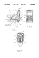
- FIG. 1 shows the first lever mechanism in its clamping position
- FIG. 2 shows the first lever mechanism in a partially unclamped position
- FIG. 3 shows the first lever mechanism in a more partially unclamped position
- FIG. 4 shows the first lever mechanism in its completely unclamped position
- FIGS. 5A and 5B are sections on A--A and B--B in FIG. 1;
- FIG. 6 shows the second lever mechanism in its clamping position
- FIG. 7 shows the second lever mechanism in a partially unclamped position
- FIG. 8 shows the second lever mechanism in a more partially unclamped position
- FIG. 9 shows the second lever mechanism in its completely unclamped position
- FIGS. 10A and 10B are sections on A--A and B--B in FIG. 6.
- a first lever assembly 1 is shown attached, via a support block 2, to a panel 3 which carries a printed circuit board 3'.
- the support block 2 is held on the panel 3 by a spring 8 as described below, but could be additionally secured to the panel 3 by screws, a snap-fit assembly, or the like if desired.
- Pivotally mounted in elongate slots 2' on the support block 2 is a first lever 4.
- the lever 4 comprises two sections (see FIGS. 5A & 5B) which fit around the support block 2 and a second lever 9 and which also provide a pivot pin 14 against which is engaged a further, coil, spring 15 which biases the first lever away from the panel and provides a clamping force between the panel and housing in use, via the lever 4.
- the lever 4 has, on one edge, a lug 5 which, when in a locked position, engages with a lip 6 protruding from the inner edge of a housing 7 to clamp the panel in position as shown. On the same edge an opposing lug 5' is formed which engages with the opposite side of the lip 6 during unlatching, to ensure removal of the panel from the housing.
- the spring 8 Connected to the support block 2 is the spring 8 which sits within the lever 4 and urges it into an unclamped position (shown in FIG. 3), in which the lug 5 is disengaged from the lip 6.
- the spring 8 has a clip 8' which engages the surface of the panel 3 to resist removal of the block 2 from the panel 3.
- the second lever 9 is pivotally mounted in recesses on the first lever 4.
- One end of the lever 9 is formed into a surface 9' so that it can be easily depressed.
- the opposite end of the lever 9 pivots.
- This end of the second lever 9 is shaped to provide a hook 10 so as to be engageable with a lip 11 positioned on the support block 2 as shown in FIG. 1.
- FIGS. 2 to 4 it is shown in a position disengaged from the lip 11.
- the spring 8 exerts a force on the second lever 9, which pivots to engage the hook 10 with the lip 11 thus holding the whole mechanism in a clamping position due to the pivotal mounting of the second lever 9 on the first lever 4.
- the second lever 9 is depressed, this causes it to rotate and the hook 10 of second lever 9 disengages from the lip 11 (as shown in FIG. 2) so that the spring 8 then urges the lever 4 into the unclamped position.
- the lever 9 is depressed, disengaging the lever 9 from the lip 11, and allowing the force of the spring 8 to move the lever 4 outward to the unclamped position.
- the engagement of the lug 5' against the opposite side of the lip 6 ensures detachment so that the panel can then be removed.
- the second example shown in FIGS. 6 to 10 is substantially similar and the same reference numerals have been used therefore.
- the significant differences are (a) that the spring 8 is an integral part of the second lever 9 and bears only against the underside of the first lever 4, (b) that a separate spring clip 8' is used to secure the support 2 to the panel 3, and (c) that a cam surface 16 is formed on one side of the pivot pin 14 so as to be engaged by the spring 15.
- the functions of the springs 8 & 15 and the spring clip 8' are separated and the spring 15 additionally serves to bias the lever 4 to the unlatched position, the spring 8 serving only to bias the second lever 9 relative to the first lever and the clip 8' serving to retain the support 2 on the panel.
- the axis of the slots 2' is inclined to the longitudinal axis of the spring 15 and to the general direction of the support 2 and this helps to ensure engagement of the lugs 5 on the lip 6 as the lever pivots and compresses the spring.
- a lock mechanism may be provided between the second and first levers in order to lock the second lever in the latched position.
- a spring loaded locking peg may be provided on the first or second levers and may be freed to move or locked in the engaged position by a suitable key-operated lock, thus allowing the latch to be set with a key for either normal push button operation, i.e. pushing on the second lever to release the first lever, or in a mode in which the latch may be slammed shut but require operation of the lock to release it before pushing on the secondary lever allows the latch to be opened.
Abstract
Description
Claims (19)
Applications Claiming Priority (2)
| Application Number | Priority Date | Filing Date | Title |
|---|---|---|---|
| GB9417194 | 1994-08-25 | ||
| GB9417194A GB9417194D0 (en) | 1994-08-25 | 1994-08-25 | Lever mechanism |
Publications (1)
| Publication Number | Publication Date |
|---|---|
| US5629836A true US5629836A (en) | 1997-05-13 |
Family
ID=10760402
Family Applications (1)
| Application Number | Title | Priority Date | Filing Date |
|---|---|---|---|
| US08/519,607 Expired - Fee Related US5629836A (en) | 1994-08-25 | 1995-08-25 | Lever mechanism |
Country Status (4)
| Country | Link |
|---|---|
| US (1) | US5629836A (en) |
| EP (1) | EP0699019B1 (en) |
| DE (1) | DE69529254T2 (en) |
| GB (1) | GB9417194D0 (en) |
Cited By (45)
| Publication number | Priority date | Publication date | Assignee | Title |
|---|---|---|---|---|
| US5822196A (en) * | 1996-06-05 | 1998-10-13 | Compaq Computer Corporation | Securing a card in an electronic device |
| US5902144A (en) * | 1997-08-15 | 1999-05-11 | Intel Corporation | Integrated circuit package burn-in socket linkage system |
| US5922060A (en) * | 1996-12-31 | 1999-07-13 | Compaq Computer Corporation | Expansion card insertion and removal |
| US5940276A (en) * | 1995-06-12 | 1999-08-17 | Siemens Aktiengesellschaft | Front system of a printed circuit board assembly having an integrated push-button element for active-passive switching |
| US5943482A (en) * | 1996-06-05 | 1999-08-24 | Compaq Computer Corporation | Expansion card insertion and removal |
| US6052288A (en) * | 1998-06-18 | 2000-04-18 | Compaq Computer Corp. | Swell-latch printed circuit board engagement mechanism |
| US6073196A (en) * | 1996-06-05 | 2000-06-06 | Compaq Computer Corporation | Using communication cycles for connecting and disconnecting devices in a computer system |
| US6098132A (en) * | 1996-06-05 | 2000-08-01 | Compaq Computer Corporation | Installation and removal of components of a computer |
| US6101322A (en) * | 1996-06-05 | 2000-08-08 | Compaq Computer Corporation | Removal and insertion of expansion cards in a computer system |
| US6220879B1 (en) * | 1998-12-28 | 2001-04-24 | Elma Electric Ag | Plug module with active-passive switching |
| US6266253B1 (en) * | 1998-02-23 | 2001-07-24 | Siemens Aktiengesellschaft | Rack system for insertion of electrical printed circuit board assemblies using centering and contact elements |
| US6366457B1 (en) * | 2000-08-30 | 2002-04-02 | International Business Machines Corporation | Bracket for mounting a computer drive device |
| US6371778B1 (en) * | 2001-01-18 | 2002-04-16 | Japan Aviation Electronics Industry, Limited | Connector assembly with manipulation mechanism having gear member and lever member |
| US20020090851A1 (en) * | 2001-01-09 | 2002-07-11 | Wrycraft Sean Conor | Ejector mechanism |
| US6515866B2 (en) * | 1998-12-23 | 2003-02-04 | Elma Electronic Ag | Plug module with active-passive switching |
| US20030030991A1 (en) * | 2001-08-10 | 2003-02-13 | Riddiford Martin P. | Support module ejection mechanism |
| US20030145705A1 (en) * | 2002-02-04 | 2003-08-07 | Blaine Miller | Fence |
| US20030156399A1 (en) * | 2002-02-15 | 2003-08-21 | Cerniglia Sean A. | Integrated bulkhead handle assembly |
| US20030194892A1 (en) * | 1999-12-23 | 2003-10-16 | Werner Korber | Actuator element for levering in and out printed circuit modules with locking slide, front element for a printed circuit module with actuator element, and subrack that receives printed circuit modules |
| US20040040117A1 (en) * | 2002-09-04 | 2004-03-04 | Purcell Brackets, Inc. | Ejector handle |
| US6791843B1 (en) | 2003-06-11 | 2004-09-14 | Hewlett-Packard Development Company, L.P. | Parallel board connection system and method |
| US20040184228A1 (en) * | 2003-01-29 | 2004-09-23 | Kabushiki Kaisha Toshiba | Electronic apparatus with latch mechanism to fix housings overlaid and connected by hinges |
| US20040219811A1 (en) * | 2003-04-29 | 2004-11-04 | International Business Machines Corporation | Apparatus for positioning an electrical assembly within a housing |
| US20040252471A1 (en) * | 2003-06-11 | 2004-12-16 | Hewlett-Packard Development Company, L.P. | Computer system with movable card guide |
| US20040257777A1 (en) * | 2003-06-20 | 2004-12-23 | Hewlett-Packard Development Company, L.P. | Electronic system with a movable printed circuit assembly |
| US20050117316A1 (en) * | 2001-11-08 | 2005-06-02 | Wrycraft Sean C. | Rack-mountable systems |
| US7251145B1 (en) * | 2004-08-18 | 2007-07-31 | Sun Microsystems, Inc. | Inject/eject mechanism for circuit boards |
| US7349228B1 (en) * | 2003-11-24 | 2008-03-25 | Extreme Networks | Ejector assembly for rack-mounted computing devices |
| US20100265679A1 (en) * | 2009-04-15 | 2010-10-21 | Radiall | Locking assembly for locking an electronics card to a rack |
| US20100328876A1 (en) * | 2008-04-29 | 2010-12-30 | Mark H Ruch | Ejection Mechanisms For Computer Equipment |
| US20110073505A1 (en) * | 2009-09-29 | 2011-03-31 | Kurt Stiehl | Button mechanisms for electronic device cases |
| US8292647B1 (en) * | 2011-06-13 | 2012-10-23 | Tyco Electronics Corporation | Socket connector |
| US8714528B1 (en) | 2013-02-18 | 2014-05-06 | Otis Young | Trailer jack plunger pin release lever system |
| US8925179B2 (en) | 2011-08-19 | 2015-01-06 | Gables Engineering, Inc. | Mounting and fastening mechanism |
| US20170329371A1 (en) * | 2016-05-11 | 2017-11-16 | Facebook, Inc. | Modular network switches, associated structures, and associated methods of manufacture and use |
| US9988021B1 (en) | 2013-02-18 | 2018-06-05 | Otis Young | Trailer jack plunger pin release system |
| US10110978B2 (en) | 2016-02-19 | 2018-10-23 | Facebook, Inc. | Wavelength division multiplexer with packet switching based on header information or performance metric information for optical channels |
| US10374709B2 (en) | 2017-07-20 | 2019-08-06 | Facebook, Inc. | Chromatic dispersion management |
| US10425331B2 (en) | 2017-10-04 | 2019-09-24 | Facebook, Inc. | Pre-routing device for data centers |
| US10476816B2 (en) | 2017-09-15 | 2019-11-12 | Facebook, Inc. | Lite network switch architecture |
| US10645027B2 (en) | 2016-09-30 | 2020-05-05 | Facebook, Inc. | Network switches configured to employ optical or electrical interfaces |
| US20200321730A1 (en) * | 2019-06-21 | 2020-10-08 | Intel Corporation | Small form factor connection mechanism for a card to card connector |
| US10873544B2 (en) | 2017-09-14 | 2020-12-22 | Facebook, Inc. | Switching using a power bar pass-through card |
| US20210364019A1 (en) * | 2020-05-25 | 2021-11-25 | Fivetech Technology Inc. | Fastener structure |
| US20220304177A1 (en) * | 2021-03-18 | 2022-09-22 | Dell Products, Lp | Tolerance absorbing lever mechanism |
Families Citing this family (8)
| Publication number | Priority date | Publication date | Assignee | Title |
|---|---|---|---|---|
| EP0917416A1 (en) * | 1997-11-18 | 1999-05-19 | Dzus Fastener Europe Limited | Latch assembly |
| GB2334151B (en) * | 1998-02-05 | 2002-06-19 | Vero Electronics Ltd | Injector/ejector device |
| FR2779901B1 (en) | 1998-06-12 | 2000-09-01 | Sextant Avionique | DEVICE FOR INSERTING, EXTRACTING AND LOCKING A MODULE IN A BAY |
| EP1453365B1 (en) * | 1998-12-28 | 2006-06-28 | Elma Electronic Ag | Plug-in unit with active/passive switching and lever for insertion and removal of such plug-in unit |
| AU2002307610A1 (en) * | 2002-04-26 | 2003-11-10 | Telefonaktiebolaget Lm Ericsson | Board injector/extractor |
| DK1578183T3 (en) * | 2004-03-19 | 2008-08-18 | Elma Electronic Ag | Insertion and removal device for plug modules |
| KR100629958B1 (en) | 2005-01-15 | 2006-09-28 | 황동원 | Bga type socket for integrated circuit used in test and burn-in |
| US9730356B2 (en) | 2013-06-28 | 2017-08-08 | Hewlett Packard Enterprise Development Lp | Lever unit |
Citations (7)
| Publication number | Priority date | Publication date | Assignee | Title |
|---|---|---|---|---|
| US2869909A (en) * | 1955-05-11 | 1959-01-20 | Mc Graw Edison Co | Latch |
| US2872234A (en) * | 1957-02-15 | 1959-02-03 | Earl M Brinton | Latch |
| US4699594A (en) * | 1985-03-11 | 1987-10-13 | Siemens Aktiengesellschaft | Plug-in and disconnect aid |
| JPH01269762A (en) * | 1988-04-22 | 1989-10-27 | Tokai Shinku Kenkyusho:Kk | Clamp mechanism of door of vacuum chamber and working box with vacuum chamber |
| US5293303A (en) * | 1991-12-11 | 1994-03-08 | Bicc Public Limited Company | Circuit board injector/ejector device for a circuit board enclosure |
| US5373419A (en) * | 1992-09-11 | 1994-12-13 | Dzus Fastener Europe Limited | Lever mechanism |
| US5504656A (en) * | 1994-08-12 | 1996-04-02 | Schroff Gmbh | Device for removing a plug-in module |
Family Cites Families (4)
| Publication number | Priority date | Publication date | Assignee | Title |
|---|---|---|---|---|
| DE7724549U1 (en) | 1977-08-06 | 1978-01-19 | Robert Bosch Gmbh, 7000 Stuttgart | Insertion and removal aid |
| US4157583A (en) | 1977-11-04 | 1979-06-05 | General Electric Company | Circuit board clamping assembly |
| DE3732892A1 (en) | 1987-09-30 | 1989-04-20 | Festo Kg | Arrangement consisting of a retaining device and at least one support for, for example, electrical or pneumatic components |
| ES2014614A6 (en) | 1989-05-10 | 1990-07-16 | Telefonica Nacional Espana Co | Screening edge mask for printed circuit board, with withdrawing-retaining mechanism |
-
1994
- 1994-08-25 GB GB9417194A patent/GB9417194D0/en active Pending
-
1995
- 1995-08-23 DE DE69529254T patent/DE69529254T2/en not_active Expired - Fee Related
- 1995-08-23 EP EP95305881A patent/EP0699019B1/en not_active Expired - Lifetime
- 1995-08-25 US US08/519,607 patent/US5629836A/en not_active Expired - Fee Related
Patent Citations (7)
| Publication number | Priority date | Publication date | Assignee | Title |
|---|---|---|---|---|
| US2869909A (en) * | 1955-05-11 | 1959-01-20 | Mc Graw Edison Co | Latch |
| US2872234A (en) * | 1957-02-15 | 1959-02-03 | Earl M Brinton | Latch |
| US4699594A (en) * | 1985-03-11 | 1987-10-13 | Siemens Aktiengesellschaft | Plug-in and disconnect aid |
| JPH01269762A (en) * | 1988-04-22 | 1989-10-27 | Tokai Shinku Kenkyusho:Kk | Clamp mechanism of door of vacuum chamber and working box with vacuum chamber |
| US5293303A (en) * | 1991-12-11 | 1994-03-08 | Bicc Public Limited Company | Circuit board injector/ejector device for a circuit board enclosure |
| US5373419A (en) * | 1992-09-11 | 1994-12-13 | Dzus Fastener Europe Limited | Lever mechanism |
| US5504656A (en) * | 1994-08-12 | 1996-04-02 | Schroff Gmbh | Device for removing a plug-in module |
Cited By (66)
| Publication number | Priority date | Publication date | Assignee | Title |
|---|---|---|---|---|
| US5940276A (en) * | 1995-06-12 | 1999-08-17 | Siemens Aktiengesellschaft | Front system of a printed circuit board assembly having an integrated push-button element for active-passive switching |
| US6069796A (en) * | 1996-06-05 | 2000-05-30 | Sharp, Comfort, & Merrett, P.C. | Securing a card in an electronic device |
| US5943482A (en) * | 1996-06-05 | 1999-08-24 | Compaq Computer Corporation | Expansion card insertion and removal |
| US6073196A (en) * | 1996-06-05 | 2000-06-06 | Compaq Computer Corporation | Using communication cycles for connecting and disconnecting devices in a computer system |
| US6098132A (en) * | 1996-06-05 | 2000-08-01 | Compaq Computer Corporation | Installation and removal of components of a computer |
| US6101322A (en) * | 1996-06-05 | 2000-08-08 | Compaq Computer Corporation | Removal and insertion of expansion cards in a computer system |
| US5822196A (en) * | 1996-06-05 | 1998-10-13 | Compaq Computer Corporation | Securing a card in an electronic device |
| US5922060A (en) * | 1996-12-31 | 1999-07-13 | Compaq Computer Corporation | Expansion card insertion and removal |
| US5902144A (en) * | 1997-08-15 | 1999-05-11 | Intel Corporation | Integrated circuit package burn-in socket linkage system |
| US6266253B1 (en) * | 1998-02-23 | 2001-07-24 | Siemens Aktiengesellschaft | Rack system for insertion of electrical printed circuit board assemblies using centering and contact elements |
| US6052288A (en) * | 1998-06-18 | 2000-04-18 | Compaq Computer Corp. | Swell-latch printed circuit board engagement mechanism |
| US6515866B2 (en) * | 1998-12-23 | 2003-02-04 | Elma Electronic Ag | Plug module with active-passive switching |
| US6220879B1 (en) * | 1998-12-28 | 2001-04-24 | Elma Electric Ag | Plug module with active-passive switching |
| US6741479B2 (en) * | 1999-12-23 | 2004-05-25 | Rittal Res Electronic Systems Gmbh & Co. Kg | Actuator element for levering in and out printed circuit modules with locking slide, front element for a printed circuit module with actuator element, and subrack that receives printed circuit modules |
| US20030194892A1 (en) * | 1999-12-23 | 2003-10-16 | Werner Korber | Actuator element for levering in and out printed circuit modules with locking slide, front element for a printed circuit module with actuator element, and subrack that receives printed circuit modules |
| US6366457B1 (en) * | 2000-08-30 | 2002-04-02 | International Business Machines Corporation | Bracket for mounting a computer drive device |
| US6796817B2 (en) | 2001-01-09 | 2004-09-28 | Sun Microsystems, Inc. | Circuit board ejector mechanism including flexible coupling |
| US20020090851A1 (en) * | 2001-01-09 | 2002-07-11 | Wrycraft Sean Conor | Ejector mechanism |
| US6371778B1 (en) * | 2001-01-18 | 2002-04-16 | Japan Aviation Electronics Industry, Limited | Connector assembly with manipulation mechanism having gear member and lever member |
| US20030030991A1 (en) * | 2001-08-10 | 2003-02-13 | Riddiford Martin P. | Support module ejection mechanism |
| US6912132B2 (en) * | 2001-08-10 | 2005-06-28 | Sun Microsystems, Inc. | Support module ejection mechanism |
| US20050117316A1 (en) * | 2001-11-08 | 2005-06-02 | Wrycraft Sean C. | Rack-mountable systems |
| US20030145705A1 (en) * | 2002-02-04 | 2003-08-07 | Blaine Miller | Fence |
| US20030156399A1 (en) * | 2002-02-15 | 2003-08-21 | Cerniglia Sean A. | Integrated bulkhead handle assembly |
| US20040040117A1 (en) * | 2002-09-04 | 2004-03-04 | Purcell Brackets, Inc. | Ejector handle |
| US20040184228A1 (en) * | 2003-01-29 | 2004-09-23 | Kabushiki Kaisha Toshiba | Electronic apparatus with latch mechanism to fix housings overlaid and connected by hinges |
| US20040219811A1 (en) * | 2003-04-29 | 2004-11-04 | International Business Machines Corporation | Apparatus for positioning an electrical assembly within a housing |
| US6884096B2 (en) * | 2003-04-29 | 2005-04-26 | International Business Machines Corporation | Apparatus for positioning an electrical assembly within a housing |
| US20050277311A1 (en) * | 2003-06-11 | 2005-12-15 | Hewlett-Packard Development Company, L.P. | Computer system with movable card guide |
| US20040252471A1 (en) * | 2003-06-11 | 2004-12-16 | Hewlett-Packard Development Company, L.P. | Computer system with movable card guide |
| US6967847B2 (en) | 2003-06-11 | 2005-11-22 | Hewlett-Packard Development Company, L.P. | Computer system with movable card guide |
| US6791843B1 (en) | 2003-06-11 | 2004-09-14 | Hewlett-Packard Development Company, L.P. | Parallel board connection system and method |
| US7453701B2 (en) | 2003-06-11 | 2008-11-18 | Hewlett-Packard Development Company, L.P. | Computer system with movable card guide |
| US20040257777A1 (en) * | 2003-06-20 | 2004-12-23 | Hewlett-Packard Development Company, L.P. | Electronic system with a movable printed circuit assembly |
| US6956746B2 (en) | 2003-06-20 | 2005-10-18 | Hewlett-Packard Development Company, L.P. | Electronic system with a movable printed circuit assembly |
| US7349228B1 (en) * | 2003-11-24 | 2008-03-25 | Extreme Networks | Ejector assembly for rack-mounted computing devices |
| US7251145B1 (en) * | 2004-08-18 | 2007-07-31 | Sun Microsystems, Inc. | Inject/eject mechanism for circuit boards |
| US8897004B2 (en) * | 2008-04-29 | 2014-11-25 | Hewlett-Packard Development Company, L.P. | Ejection mechanisms for computer equipment |
| US20100328876A1 (en) * | 2008-04-29 | 2010-12-30 | Mark H Ruch | Ejection Mechanisms For Computer Equipment |
| US8295055B2 (en) * | 2009-04-15 | 2012-10-23 | Radiall | Locking assembly for locking an electronics card to a rack |
| US20100265679A1 (en) * | 2009-04-15 | 2010-10-21 | Radiall | Locking assembly for locking an electronics card to a rack |
| US20110073505A1 (en) * | 2009-09-29 | 2011-03-31 | Kurt Stiehl | Button mechanisms for electronic device cases |
| US8167126B2 (en) * | 2009-09-29 | 2012-05-01 | Apple Inc. | Button mechanisms for electronic device cases |
| US8292647B1 (en) * | 2011-06-13 | 2012-10-23 | Tyco Electronics Corporation | Socket connector |
| US8925179B2 (en) | 2011-08-19 | 2015-01-06 | Gables Engineering, Inc. | Mounting and fastening mechanism |
| US8714528B1 (en) | 2013-02-18 | 2014-05-06 | Otis Young | Trailer jack plunger pin release lever system |
| US9988021B1 (en) | 2013-02-18 | 2018-06-05 | Otis Young | Trailer jack plunger pin release system |
| US9809204B2 (en) | 2013-02-18 | 2017-11-07 | Otis Young | Trailer jack plunger pin release lever system |
| US10110978B2 (en) | 2016-02-19 | 2018-10-23 | Facebook, Inc. | Wavelength division multiplexer with packet switching based on header information or performance metric information for optical channels |
| US20170329371A1 (en) * | 2016-05-11 | 2017-11-16 | Facebook, Inc. | Modular network switches, associated structures, and associated methods of manufacture and use |
| US10028417B2 (en) | 2016-05-11 | 2018-07-17 | Facebook, Inc. | Modular network switches, associated structures, and associated methods of manufacture and use |
| US9949409B2 (en) | 2016-05-11 | 2018-04-17 | Facebook, Inc. | Modular network switches, associated structures, and associated methods of manufacture and use |
| US10165709B2 (en) * | 2016-05-11 | 2018-12-25 | Facebook, Inc. | Modular network switches, associated structures, and associated methods of manufacture and use |
| US10271461B2 (en) | 2016-05-11 | 2019-04-23 | Facebook, Inc. | Modular network switches, associated structures, and associated methods of manufacture and use |
| US10356955B2 (en) | 2016-05-11 | 2019-07-16 | Facebook, Inc. | Modular network switches, associated structures, and associated methods of manufacture and use |
| US10645027B2 (en) | 2016-09-30 | 2020-05-05 | Facebook, Inc. | Network switches configured to employ optical or electrical interfaces |
| US10374709B2 (en) | 2017-07-20 | 2019-08-06 | Facebook, Inc. | Chromatic dispersion management |
| US10873544B2 (en) | 2017-09-14 | 2020-12-22 | Facebook, Inc. | Switching using a power bar pass-through card |
| US10476816B2 (en) | 2017-09-15 | 2019-11-12 | Facebook, Inc. | Lite network switch architecture |
| US11057316B2 (en) | 2017-09-15 | 2021-07-06 | Facebook, Inc. | Lite network switch architecture |
| US10425331B2 (en) | 2017-10-04 | 2019-09-24 | Facebook, Inc. | Pre-routing device for data centers |
| US11012354B2 (en) | 2017-10-04 | 2021-05-18 | Facebook, Inc. | Pre-routing device for data centers |
| US20200321730A1 (en) * | 2019-06-21 | 2020-10-08 | Intel Corporation | Small form factor connection mechanism for a card to card connector |
| US20210364019A1 (en) * | 2020-05-25 | 2021-11-25 | Fivetech Technology Inc. | Fastener structure |
| US20220304177A1 (en) * | 2021-03-18 | 2022-09-22 | Dell Products, Lp | Tolerance absorbing lever mechanism |
| US11606874B2 (en) * | 2021-03-18 | 2023-03-14 | Dell Products L.P. | Tolerance absorbing lever mechanism |
Also Published As
| Publication number | Publication date |
|---|---|
| GB9417194D0 (en) | 1994-10-12 |
| EP0699019B1 (en) | 2003-01-02 |
| DE69529254T2 (en) | 2003-06-26 |
| EP0699019A1 (en) | 1996-02-28 |
| DE69529254D1 (en) | 2003-02-06 |
Similar Documents
| Publication | Publication Date | Title |
|---|---|---|
| US5629836A (en) | Lever mechanism | |
| EP0587451B1 (en) | Lever mechanism | |
| US6373713B1 (en) | Single handle printed circuit board assembly insertion, extraction, sensing and locking mechanism | |
| CA1273699A (en) | Mount for electronic instrument | |
| US6275378B1 (en) | Safety lock for notebook-type computer dock | |
| US5401179A (en) | Locking mechanism for a connector assembly of low engaging/disengaging force type | |
| US5797772A (en) | Connector provided with a retainer | |
| US6266248B1 (en) | Lockable latch and switch actuator assembly for a circuit card | |
| KR100310428B1 (en) | Connector for flat flexible circuitry | |
| US6463774B2 (en) | Push lock | |
| US4787858A (en) | Latching system for computer plug | |
| US4947289A (en) | Latch mechanism for a plug-in cartridge or the like | |
| US6646883B2 (en) | Insertion latch and ejectable pull handle for rack mounted electronic devices | |
| US5364287A (en) | Connector restraining apparatus | |
| JPH09180570A (en) | Mounting structure for switch box | |
| JPH07192800A (en) | Electric connector with terminal position guarantee mechanism | |
| US5963422A (en) | Systems and methods for releaseably securing an article within a computer system | |
| JPH06245348A (en) | Lock for electronic unit | |
| JP7329569B2 (en) | Retaining mechanism for attaching a technical equipment unit to a mounting rail and technical equipment unit having such a retaining mechanism | |
| US20230028263A1 (en) | Card retainers | |
| CN217903335U (en) | Battery cover double-locking mechanism | |
| CN220014763U (en) | Handle, dummy panel and communication device | |
| JP4016482B2 (en) | Unit with terminal block | |
| US11547010B2 (en) | Latching mechanism | |
| JPH1167346A (en) | Fitting/removing structure for connector |
Legal Events
| Date | Code | Title | Description |
|---|---|---|---|
| AS | Assignment |
Owner name: DZUS FASTENER EUROPE LTD., UNITED KINGDOM Free format text: ASSIGNMENT OF ASSIGNORS INTEREST;ASSIGNOR:WRIGHT, ANDREW CHARLES WALDEN;REEL/FRAME:007834/0305 Effective date: 19950911 |
|
| FEPP | Fee payment procedure |
Free format text: PAYOR NUMBER ASSIGNED (ORIGINAL EVENT CODE: ASPN); ENTITY STATUS OF PATENT OWNER: LARGE ENTITY |
|
| AS | Assignment |
Owner name: MCKECHNIE SPECIALIST PRODUCTS LIMITED, UNITED KING Free format text: ASSIGNMENT OF ASSIGNORS INTEREST;ASSIGNOR:DZUS FASTENER EUROPE LIMITED;REEL/FRAME:010927/0344 Effective date: 20000427 |
|
| FPAY | Fee payment |
Year of fee payment: 4 |
|
| FPAY | Fee payment |
Year of fee payment: 8 |
|
| AS | Assignment |
Owner name: SOUTHCO, U.K. LIMITED, UNITED KINGDOM Free format text: ASSIGNMENT OF ASSIGNORS INTEREST;ASSIGNOR:MCKECHNIE SPECIALIST PRODUCTS LIMITED;REEL/FRAME:018171/0493 Effective date: 20041027 |
|
| REMI | Maintenance fee reminder mailed | ||
| LAPS | Lapse for failure to pay maintenance fees | ||
| STCH | Information on status: patent discontinuation |
Free format text: PATENT EXPIRED DUE TO NONPAYMENT OF MAINTENANCE FEES UNDER 37 CFR 1.362 |
|
| FP | Lapsed due to failure to pay maintenance fee |
Effective date: 20090513 |