US5631909A - Method and apparatus for determining burst errors in an error pattern - Google Patents
Method and apparatus for determining burst errors in an error pattern Download PDFInfo
- Publication number
- US5631909A US5631909A US08/454,959 US45495995A US5631909A US 5631909 A US5631909 A US 5631909A US 45495995 A US45495995 A US 45495995A US 5631909 A US5631909 A US 5631909A
- Authority
- US
- United States
- Prior art keywords
- burst
- bits
- bit
- error
- error pattern
- Prior art date
- Legal status (The legal status is an assumption and is not a legal conclusion. Google has not performed a legal analysis and makes no representation as to the accuracy of the status listed.)
- Expired - Fee Related
Links
- 238000013507 mapping Methods 0.000 claims description 3
- 241000269627 Amphiuma means Species 0.000 claims 4
- 238000007476 Maximum Likelihood Methods 0.000 description 3
- 230000007547 defect Effects 0.000 description 3
- 238000002372 labelling Methods 0.000 description 2
- 238000012986 modification Methods 0.000 description 2
- 230000004048 modification Effects 0.000 description 2
- 230000002411 adverse Effects 0.000 description 1
- 238000010586 diagram Methods 0.000 description 1
- 230000003287 optical effect Effects 0.000 description 1
- 238000012360 testing method Methods 0.000 description 1
Images


Classifications
-
- H—ELECTRICITY
- H03—ELECTRONIC CIRCUITRY
- H03M—CODING; DECODING; CODE CONVERSION IN GENERAL
- H03M13/00—Coding, decoding or code conversion, for error detection or error correction; Coding theory basic assumptions; Coding bounds; Error probability evaluation methods; Channel models; Simulation or testing of codes
- H03M13/03—Error detection or forward error correction by redundancy in data representation, i.e. code words containing more digits than the source words
- H03M13/05—Error detection or forward error correction by redundancy in data representation, i.e. code words containing more digits than the source words using block codes, i.e. a predetermined number of check bits joined to a predetermined number of information bits
- H03M13/13—Linear codes
- H03M13/17—Burst error correction, e.g. error trapping, Fire codes
-
- H—ELECTRICITY
- H03—ELECTRONIC CIRCUITRY
- H03M—CODING; DECODING; CODE CONVERSION IN GENERAL
- H03M13/00—Coding, decoding or code conversion, for error detection or error correction; Coding theory basic assumptions; Coding bounds; Error probability evaluation methods; Channel models; Simulation or testing of codes
Definitions
- This invention relates generally to error correction systems that correct errors in data encoded using an error correction code and, more particularly, to a system for counting burst errors in the decoded data.
- ECC error correction code
- ECC symbols are then appended to the data string to form data code words--data symbols plus ECC symbols--and the data code words are written to, or stored on, the disk after appropriate encoding with a modulation code.
- N code words are typically interleaved before they are recorded in a sector.
- the interleaved code words are retrieved and mathematically decoded.
- decoding errors in the data are detected and, if possible, corrected through manipulation of the associated ECC symbols [For a detailed description of decoding see Peterson and Weldon, Error Correction Codes, 2d Edition, MIT Press, 1972].
- the data recorded in a sector are retrieved from storage, they are manipulated in a conventional manner to de-interleave the N code words and determine the locations of errors and the associated error values. The system then corrects the errors by combining the error values with the associated erroneous bits or symbols.
- a random error is an independent error that occurs in a code word symbol.
- a burst error is a sequence of contiguous bits or symbols in which at least the first bit or symbol and the last bit or symbol are erroneous, and the bits or symbols between the first and last may but need not be erroneous. Burst errors result from, for example, a storage medium defect that adversely affects a portion of a sector, and thus, affects a number of the interleaved code words. As data are stored more densely, defects in the storage medium tend to involve more and more bits, and thus, produce more and more burst errors.
- Systems are more often using maximum likelihood demodulators to demodulate the retrieved data. These demodulators tend to correct random errors in the retrieved data by selecting "legitimate" sequences of bits, based on a sequence of retrieved bits that may contain one or more erroneous bits.
- the demodulator uses information about the modulation code to select, as the most likely recorded bits, a sequence of bits that is closest to the retrieved bits and meets the constraints of the modulation code.
- the maximum likelihood demodulators may actually introduce bursty errors into the demodulation, by selecting as most likely the wrong sequence of bits.
- the demodulator is more apt to make such a selection if the retrieved data are corrupted.
- sequences selected by the maximum likelihood demodulator are legitimate sequences of bits, even if they are the wrong sequences, that is, even if they are not the sequences that were recorded. These sequences are then de-interleaved and decoded to reproduce the N code words.
- the retrieved data contains too many errors the data may be mistakenly demodulated, and then interpreted as different (but legitimate) code words. This is the worst type of decoding mistake, since the system "corrects" these code words, as necessary, using the ECC, and then treats the data symbols as error-free. Accordingly, as recording density increases, it is becoming more and more important to count the number of burst errors in the N retrieved code words, so that this decoding problem can be avoided by limiting error correction to those sectors that contain a relatively small number of burst errors.
- a burst error occurs as a number of bits or symbols. Since all the bits or symbols in a burst need not be erroneous, there is an ambiguity in determining the start and length of each burst. There is thus a problem in determining if a retrieved sector of data contains a number of burst errors that exceeds the predetermined error correcting limit.
- the system examines the error pattern for the entire sector of data.
- the error pattern is determined from the error locations and the error values for the N code words. These are provided by the ECC during decoding. A zero in the pattern represents a correct bit and a one in the pattern represents an erroneous bit.
- the pattern includes the same number of bits as those recorded the sector.
- the number of burst errors in this segment of the pattern can be counted as:
- the invention is a burst error counting system that determines for each error pattern a unique, minimum number of burst errors by (i) specifying, based on the statistical operation of the system, a maximum burst length, L, which, as discussed below, is the longest burst that the system "generates;” (ii) determining the location in the error pattern of a first erroneous bit; (iii) associating the next L-1 bits with the erroneous bit; (iv) incrementing a burst counter; (v) searching for the first bit of a next burst error in the remaining bits of the error pattern; and (vi) repeating iii-v.
- the system may also store the positions of these first erroneous bits for later use.
- the system associates with each burst error at least the bits included in that burst and may associate with it a number of non-erroneous bits that follow the burst.
- the system associates with b FIRST both the sequence of bits included in the actual burst error (i.e., 1101) and the two non-erroneous bits that follow the burst. If, for example, the last bit were instead erroneous, both of the bits would be included in the actual burst error.
- the system compares the count to a predetermined burst error threshold, which is less than or equal to the number of burst errors that the system can expect in a sector of data. If the number of burst errors exceeds the threshold, the system may characterize the code words as uncorrectable. As discussed in more detail below, the threshold is based on the performance statistics of the system.
- the system counts the burst errors simultaneously from both ends of the error pattern. It thus determines the positions in the pattern of a first erroneous bit, b FIRST , and a last erroneous bit, b LAST . Next, it associates with these bits the succeeding or proceeding L-1 bits, as appropriate. If the bit position of the L-1 st bit associated with the first burst error is the same as or beyond the position of b LAST , the system determines that the two erroneous bits b FIRST and b LAST are within the same burst error, and thus, that the error pattern contains a single burst error.
- the system determines that there are at least two burst errors. It then increments its burst count by two and continues searching through the remaining error pattern for additional burst errors.
- the system associates with them the appropriate succeeding and preceding L-1 bits and again checks if they should be treated as a single burst error. If so, the system has found all of the burst errors. Accordingly, it increments its burst count by one and stops its burst counting operations. Otherwise, the system increments the burst count by two and continues searching for additional burst errors, as long as the burst count is below the burst error threshold.
- the system locates b FIRST and b LAST and sets to all zeros b FIRST and the succeeding L-1 bits and b LAST and preceding L-1 bits. It can then readily determine from the altered error pattern whether or not there are additional burst errors, by searching for any 1's in the pattern.
- the system may reduce the length of the error pattern, and free buffer space, by limiting to L-1 the number of zeros between consecutive 1's. The system then counts the burst errors by searching through the reduced number of bits.
- the system in all of its embodiments determines for an error pattern a unique, minimum count of the burst errors.
- the particular burst error patterns and locations may differ, depending on whether the system searches the error pattern from one end or both ends. However, the count of the burst errors remains the same.
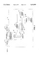
- FIG. 1 is a functional block diagram of a system constructed in accordance with the invention
- FIG. 2 is a flow chart of the operations of a decoder that is included in the system of FIG. 1;
- FIG. 3 depicts the decoder of FIG. 2 with increased storage capabilities
- FIG. 4 depicts an alternative decoder
- FIG. 5 is a flow chart of the operations of the decoder of FIG. 4.
- FIG. 1 depicts a system 10 in which an encoder 12 encodes data symbols in a conventional manner to produce error correction code (ECC) symbols.
- ECC error correction code
- the encoder 12 concatenates the ECC symbols to the data symbols to form a code word. It then interleaves N code words and sends them to a storage device 14 for storage in a sector on a recording medium, such as a magnetic disk (not shown).
- the decoder 16 demodulates, de-interleaves and decodes the data in a conventional manner in processor 17.
- the decoding produces a sector-long error pattern that consists of a sequence of zeros and ones, with ones representing erroneous bits and zeros representing nonerroneous bits. It then stores the error pattern in a buffer 18 (step 100).
- the decoder 16 determines a first potential burst error, e p1 , by associating with bit b FIRST the next L-1 bits, where L is the maximum burst length associated with the system (step 106).
- the code word error pattern is now:
- the decoder also compares its burst count to a predetermined burst error threshold, which is equal to or less than the maximum number of burst errors that the system "expects" in an error pattern that corresponds to a sector of data that is not so corrupted that the ECC may inaccurately "correct” the data (step 112).
- This burst error threshold is also determined experimentally for a particular system. For example, the system may occasionally encounter error patterns with at most two burst errors and encounter significantly more burst errors only when a sector is corrupted beyond the point at which the error correction system always correctly reproduces the recorded data. Such a system would have its threshold set to two or perhaps three, to avoid labeling good sectors as uncorrectable.
- the system stops its burst counting operation (steps 112-113). Otherwise, the system searches for the next 1 in the remaining bits in the error pattern (steps 114-116).
- the decoder 16 again begins its searches for a first 1 bit in the pattern and ends this search at the ninth bit, which becomes the next b FIRST .
- the decoder next associates the succeeding L-1, or 5, bits with b FIRST , to produce the second potential burst error, e p2 , of 111000.
- the detector 22 enables an address memory 24.
- This memory stores, in a memory location addressed by the count of burst counter 20, a bit count from an address counter 26, which counts the bits in the error pattern as these bits are searched.
- the detector 22 operates in a conventional manner to detect 1's in the error pattern.
- the detector 22 retrieves the error pattern from the error pattern buffer 18 (FIG. 1) as a serial stream of bits, and "tests" each bit to find the first 1 bit.
- the address counter 26 thus counts the bits as they are applied to the detector.
- the detector 22 could instead retrieve the error pattern in parallel from the buffer 18, and use a combinational search and counting mechanism to determine the position of a first 1 in the pattern.
- the detector 22 When the detector 22 detects the first 1 in the error pattern, it asserts a signal on line 23. The asserted signal increments the count of the burst counter 20 and enables a burst error address memory 24. The memory 24 stores the count of the address counter 26 in the memory location addressed by the burst count, to indicate the first bit position of the first burst error. The detector then leaves asserted the signal on line 25 for the next L-1 bits. Thereafter, the detector de-asserts the signal on line 25 until a next 1 is detected in the code word error pattern.
- the burst error threshold is equal to or less than the maximum number of burst errors that are expected in a sector that is not corrupted to the point that the error correction performed by the system is questionable. If the sector includes too many burst errors, it is at least somewhat likely that the corrected data are not the data that were recorded on the disk, but instead other data that were produced through a combination of inaccurate demodulation and error correction of the resulting data.
- the comparator asserts a signal on line 29 and the system 10 (FIG. 1) responds appropriately by, for example, labeling the code word as uncorrectable. It thus rejects the corrected data as inaccurate.
- the decoder 16 counts burst errors simultaneously from both ends of the error pattern.
- the decoder 16 thus includes two detectors 22-1 and 22-2 and two address counters 26-1 and 26-2, as depicted in FIG. 3.
- the detector 22-1 determines the first position of a 1 in the error pattern by examining succeeding bits of the error pattern, starting from the end of the pattern that corresponds to the start of the error pattern (step 202).
- the associated address counter 26-1 which is initially set to zero, increments its count for each bit examined by the detector 22-1 (steps 200, 204).
- the detector 22-2 starts searching for 1's from the end of the pattern that corresponds to the end of the date (step 302).
- the associated address counter 26-2 starts its count at the total bit count of the error pattern, and decrements its count for each bit examined by the detector 22-2 (steps 300, 304).
- the decoder 16 determines if the two 1's should be included in the same or different burst errors.
- the decoder 16 first stores the address count of b FIRST in the address memory, since it is the first bit of at least the first burst error in the pattern. (step 206).
- the decoder next associates L-1 bits with b FIRST and determines from the count of address counter 26-1 the position of the L-1 st bit (step 208).
- this bit position is beyond the position of b LAST , that is, if processor 27 determines that the count of address counter 26-1 is greater than the count of address counter 26-2, the system includes b FIRST and b LAST in the same burst error. The burst counter is then incremented by one and the decoder stops its burst counting operations (steps 210, 212).
- the system increments the burst counter 20 by two, associates the preceding L-1 bits with b LAST and stores the count of the address counter 26-2 in the burst error address memory 24 as the location of a second burst error (steps 211, 214, 215).
- the decoder next sets to all zeros b FIRST and the associated succeeding L-1 bits, and b LAST and the associated preceding L-1 bits. If the burst count does not exceed the burst error threshold, the system searches the remaining bits of the code word error pattern from both ends and determines the positions of any additional burst errors (steps 216-218).
- the system may use a simplified operation to determine if the number of burst errors exceeds the threshold.
- the decoder 16 searches the error pattern from both ends for b FIRST , the first 1 in the error pattern, and b LAST , the last 1 in the error pattern (step 400). It then sets to all zeros the bits b FIRST through b FIRST+L-1 and bits b LAST through b LAST- (L-1) (steps 401-402). Next, it determines if any 1's remain in the error pattern (step 403). If so, the system determines that the pattern contains three or more burst errors, and thus, that the error threshold is exceeded (step 404). Otherwise, the system determines that there are at most two burst errors, and thus, that the error correction operations accurately reproduced the recorded data (step 405).
- the system may limit to L-1 the number of consecutive zeros between any two 1's in the error pattern.
- the length of the pattern is thus reduced, without altering the burst error count, which remains at 5. If the burst errors are spread out in the error pattern, a significant amount of buffer space can be freed by limiting the included sequences of consecutive zeros.
- burst errors are determined by associating up to L-1 bits with the first bit in each segment and any remaining 1's in a segment with subsequent burst errors.
- the underlined portions As illustrated by the underlined portions:
- the burst error count remains at 5, with the second segment containing two burst errors.
- the decoder 16 counts "symbol burst errors" by first mapping the symbols that represent the error pattern to a binary sequence in which the 1's represent erroneous symbols and the 0's represent error-free symbols. Thus, the bits in the error pattern are first mapped to symbols and the symbols, in turn, are mapped to the binary sequence. The decoder then counts the bursts in the binary sequence as described above and compares the count to an associated symbol burst error threshold.
- the decoder 16 determines for each error pattern a unique, minimum number of burst errors of less than or equal to a predetermined size.
- the decoder determines burst errors based either on a number of bits or a number of symbols, as appropriate. Further, the system limits the data sectors it treats as accurately corrected to those sectors that contain fewer than a predetermined number of burst errors. In this way, the system avoids potentially misinterpreting one or more of the code words contained in the sector.
Abstract
Description
______________________________________
00100011000000000010100000000000011100000 . . .
______________________________________
__________________________________________________________________________
00100001011100010000000000000000000010100000000111110000000000 . .
__________________________________________________________________________
__________________________________________________________________________
00000000011100010000000000000000000010100000000111110000000000 . .
__________________________________________________________________________
__________________________________________________________________________
00100001011100010000000000000000000010100000000111110000000000 . .
__________________________________________________________________________
______________________________________
10000101110001000001010000011111 . . .
______________________________________
______________________________________
        100001 1110001 101 111110
______________________________________
______________________________________
        100001 111000 1 101 11111
______________________________________
__________________________________________________________________________
000000000S.sub.1 S.sub.2 00000000000S.sub.3 S.sub.4 S.sub.5 S.sub.6
S.sub.7 000000000000S.sub.8 S.sub.9 S.sub.10 00000000000 . .
__________________________________________________________________________
______________________________________
00000000011000000000001111100000000000011100000000000 . .
______________________________________
Claims (16)
Priority Applications (5)
| Application Number | Priority Date | Filing Date | Title |
|---|---|---|---|
| US08/454,959 US5631909A (en) | 1995-05-31 | 1995-05-31 | Method and apparatus for determining burst errors in an error pattern |
| PCT/US1996/007525 WO1996038923A1 (en) | 1995-05-31 | 1996-05-21 | Method and apparatus for determining burst errors in an error pattern |
| KR1019970700635A KR970705242A (en) | 1995-05-31 | 1996-05-21 | Method and Apparatus for Determining Burst Errors in Fault Patterns |
| JP8536551A JPH10503916A (en) | 1995-05-31 | 1996-05-21 | Method and apparatus for determining a burst error in an error pattern |
| EP96914761A EP0772914A4 (en) | 1995-05-31 | 1996-05-21 | Method and apparatus for determining burst errors in an error pattern |
Applications Claiming Priority (1)
| Application Number | Priority Date | Filing Date | Title |
|---|---|---|---|
| US08/454,959 US5631909A (en) | 1995-05-31 | 1995-05-31 | Method and apparatus for determining burst errors in an error pattern |
Publications (1)
| Publication Number | Publication Date |
|---|---|
| US5631909A true US5631909A (en) | 1997-05-20 |
Family
ID=23806778
Family Applications (1)
| Application Number | Title | Priority Date | Filing Date |
|---|---|---|---|
| US08/454,959 Expired - Fee Related US5631909A (en) | 1995-05-31 | 1995-05-31 | Method and apparatus for determining burst errors in an error pattern |
Country Status (5)
| Country | Link |
|---|---|
| US (1) | US5631909A (en) |
| EP (1) | EP0772914A4 (en) |
| JP (1) | JPH10503916A (en) |
| KR (1) | KR970705242A (en) |
| WO (1) | WO1996038923A1 (en) |
Cited By (18)
| Publication number | Priority date | Publication date | Assignee | Title |
|---|---|---|---|---|
| WO1998012819A1 (en) * | 1996-09-17 | 1998-03-26 | Quantum Corporation | Improved multiple-burst-correction system |
| US6067655A (en) * | 1997-08-28 | 2000-05-23 | Stmicroelectronics, N.V. | Burst error limiting symbol detector system |
| US6321357B1 (en) * | 1998-05-31 | 2001-11-20 | Innomedia Pte Ltd | Method and apparatus for burst error correction |
| US6330620B1 (en) * | 1997-12-26 | 2001-12-11 | Nec Corporation | Arrayed I/O unit close decision method and apparatus, and medium containing an arrayed I/O unit close decision program |
| US20020085644A1 (en) * | 2000-12-28 | 2002-07-04 | Atsushi Hayami | Modulation system |
| US20030023930A1 (en) * | 2001-06-14 | 2003-01-30 | Eiji Fujiwara | Burst error pattern generation method, and burst and byte error detection and correction apparatus |
| US6697976B1 (en) * | 1999-07-30 | 2004-02-24 | Hitachi, Ltd. | Performance evaluation method, performance evaluation system, and information storage apparatus using same |
| US6744748B1 (en) * | 2000-05-25 | 2004-06-01 | Vtech Communications Ltd. | Method and apparatus for monitoring errors in a wireless transceiver |
| US20040205381A1 (en) * | 2003-02-20 | 2004-10-14 | Nec Corporation | Disk array device |
| US20040250196A1 (en) * | 2003-06-04 | 2004-12-09 | Hassner Martin Aureliano | Method for correcting a burst of errors plus random errors |
| US20050097429A1 (en) * | 2001-08-09 | 2005-05-05 | Propp Michael B. | Error correction process and mechanism |
| US20050229070A1 (en) * | 2004-03-31 | 2005-10-13 | Sanyo Electric Co., Ltd. | Method of detecting error location, and error detection circuit, error correction circuit, and reproducing apparatus using the method |
| US20060062046A1 (en) * | 2004-06-14 | 2006-03-23 | Stmicroelectronics S.R.L. | Data control unit capable of correcting boot errors, and corresponding self-correction method |
| US20060242546A1 (en) * | 2002-04-05 | 2006-10-26 | Alion Science And Technology Corp. | Decoding method and apparatus |
| US20090138663A1 (en) * | 2007-11-27 | 2009-05-28 | Samsung Electronics Co., Ltd. | Cache memory capable of adjusting burst length of write-back data in write-back operation |
| US20150154065A1 (en) * | 2013-12-04 | 2015-06-04 | Seagate Technology Llc | Adaptive read error recovery for memory devices |
| US9378083B2 (en) | 2013-12-04 | 2016-06-28 | Seagate Technology Llc | Adaptive read error recovery for memory devices |
| US10268541B2 (en) * | 2016-08-15 | 2019-04-23 | Samsung Electronics Co., Ltd. | DRAM assist error correction mechanism for DDR SDRAM interface |
Citations (4)
| Publication number | Priority date | Publication date | Assignee | Title |
|---|---|---|---|---|
| US3622984A (en) * | 1969-11-05 | 1971-11-23 | Ibm | Error correcting system and method |
| US4059825A (en) * | 1976-10-12 | 1977-11-22 | Greene Edward P | Burst/slip correction decoder and method |
| US5036514A (en) * | 1989-11-09 | 1991-07-30 | International Business Machines Corp. | Apparatus and method for isolating and predicting errors in a local area network |
| US5513185A (en) * | 1992-11-23 | 1996-04-30 | At&T Corp. | Method and apparatus for transmission link error rate monitoring |
Family Cites Families (4)
| Publication number | Priority date | Publication date | Assignee | Title |
|---|---|---|---|---|
| US3725859A (en) * | 1971-06-14 | 1973-04-03 | Texas Instruments Inc | Burst error detection and correction system |
| JPS5898814A (en) * | 1981-12-08 | 1983-06-11 | Sony Corp | Error data interpolating device |
| JPH0618358B2 (en) * | 1985-04-09 | 1994-03-09 | 沖電気工業株式会社 | Error control coding system |
| JP2559923B2 (en) * | 1990-09-04 | 1996-12-04 | インターナショナル・ビジネス・マシーンズ・コーポレイション | Method and apparatus for isolating errors occurring in serially connected links |
-
1995
- 1995-05-31 US US08/454,959 patent/US5631909A/en not_active Expired - Fee Related
-
1996
- 1996-05-21 KR KR1019970700635A patent/KR970705242A/en not_active Application Discontinuation
- 1996-05-21 JP JP8536551A patent/JPH10503916A/en active Pending
- 1996-05-21 EP EP96914761A patent/EP0772914A4/en not_active Withdrawn
- 1996-05-21 WO PCT/US1996/007525 patent/WO1996038923A1/en not_active Application Discontinuation
Patent Citations (4)
| Publication number | Priority date | Publication date | Assignee | Title |
|---|---|---|---|---|
| US3622984A (en) * | 1969-11-05 | 1971-11-23 | Ibm | Error correcting system and method |
| US4059825A (en) * | 1976-10-12 | 1977-11-22 | Greene Edward P | Burst/slip correction decoder and method |
| US5036514A (en) * | 1989-11-09 | 1991-07-30 | International Business Machines Corp. | Apparatus and method for isolating and predicting errors in a local area network |
| US5513185A (en) * | 1992-11-23 | 1996-04-30 | At&T Corp. | Method and apparatus for transmission link error rate monitoring |
Cited By (34)
| Publication number | Priority date | Publication date | Assignee | Title |
|---|---|---|---|---|
| US5771246A (en) * | 1996-09-17 | 1998-06-23 | Quantum Corporation | Multiple-burst-correction system |
| WO1998012819A1 (en) * | 1996-09-17 | 1998-03-26 | Quantum Corporation | Improved multiple-burst-correction system |
| US6067655A (en) * | 1997-08-28 | 2000-05-23 | Stmicroelectronics, N.V. | Burst error limiting symbol detector system |
| US6330620B1 (en) * | 1997-12-26 | 2001-12-11 | Nec Corporation | Arrayed I/O unit close decision method and apparatus, and medium containing an arrayed I/O unit close decision program |
| US6321357B1 (en) * | 1998-05-31 | 2001-11-20 | Innomedia Pte Ltd | Method and apparatus for burst error correction |
| US6697976B1 (en) * | 1999-07-30 | 2004-02-24 | Hitachi, Ltd. | Performance evaluation method, performance evaluation system, and information storage apparatus using same |
| US6744748B1 (en) * | 2000-05-25 | 2004-06-01 | Vtech Communications Ltd. | Method and apparatus for monitoring errors in a wireless transceiver |
| US7003046B2 (en) * | 2000-12-28 | 2006-02-21 | Victor Company Of Japan, Ltd. | Modulation system |
| US20020085644A1 (en) * | 2000-12-28 | 2002-07-04 | Atsushi Hayami | Modulation system |
| US20030023930A1 (en) * | 2001-06-14 | 2003-01-30 | Eiji Fujiwara | Burst error pattern generation method, and burst and byte error detection and correction apparatus |
| US6990625B2 (en) * | 2001-06-14 | 2006-01-24 | Fanuc Ltd | Burst error pattern generation method, and burst and byte error detection correction apparatus |
| US20080270871A1 (en) * | 2001-08-09 | 2008-10-30 | Adaptive Networks, Inc. | Error correction process and mechanism |
| US20050097429A1 (en) * | 2001-08-09 | 2005-05-05 | Propp Michael B. | Error correction process and mechanism |
| US7398451B2 (en) * | 2001-08-09 | 2008-07-08 | Adaptive Networks, Inc. | Error correction process and mechanism |
| US10355718B2 (en) * | 2001-08-09 | 2019-07-16 | Adaptive Networks, Inc. | Error correction process and mechanism |
| US20060242546A1 (en) * | 2002-04-05 | 2006-10-26 | Alion Science And Technology Corp. | Decoding method and apparatus |
| US7409579B2 (en) * | 2003-02-20 | 2008-08-05 | Nec Corporation | Disk array device having point value added or subtracted for determining whether device is degraded |
| US20040205381A1 (en) * | 2003-02-20 | 2004-10-14 | Nec Corporation | Disk array device |
| US7272777B2 (en) * | 2003-06-04 | 2007-09-18 | International Business Machines Corporation | Method for correcting a burst of errors plus random errors |
| US20040250196A1 (en) * | 2003-06-04 | 2004-12-09 | Hassner Martin Aureliano | Method for correcting a burst of errors plus random errors |
| US20050229070A1 (en) * | 2004-03-31 | 2005-10-13 | Sanyo Electric Co., Ltd. | Method of detecting error location, and error detection circuit, error correction circuit, and reproducing apparatus using the method |
| US7478306B2 (en) * | 2004-03-31 | 2009-01-13 | Sanyo Electric Co., L:Td. | Method of detecting error location, and error detection circuit, error correction circuit, and reproducing apparatus using the method |
| US20060062046A1 (en) * | 2004-06-14 | 2006-03-23 | Stmicroelectronics S.R.L. | Data control unit capable of correcting boot errors, and corresponding self-correction method |
| US7444543B2 (en) * | 2004-06-14 | 2008-10-28 | Irene Babudri | Data control unit capable of correcting boot errors, and corresponding self-correction method |
| US8443152B2 (en) * | 2007-11-27 | 2013-05-14 | Samsung Electronics Co. Ltd. | Cache memory capable of adjusting burst length of write-back data in write-back operation |
| US8799585B2 (en) | 2007-11-27 | 2014-08-05 | Samsung Electronics Co., Ltd. | Cache memory capable of adjusting burst length of write-back data in write-back operation |
| US20090138663A1 (en) * | 2007-11-27 | 2009-05-28 | Samsung Electronics Co., Ltd. | Cache memory capable of adjusting burst length of write-back data in write-back operation |
| US20150154065A1 (en) * | 2013-12-04 | 2015-06-04 | Seagate Technology Llc | Adaptive read error recovery for memory devices |
| US9378083B2 (en) | 2013-12-04 | 2016-06-28 | Seagate Technology Llc | Adaptive read error recovery for memory devices |
| US9397703B2 (en) * | 2013-12-04 | 2016-07-19 | Seagate Technology Llc | Adaptive read error recovery for memory devices |
| US10268541B2 (en) * | 2016-08-15 | 2019-04-23 | Samsung Electronics Co., Ltd. | DRAM assist error correction mechanism for DDR SDRAM interface |
| US10977118B2 (en) | 2016-08-15 | 2021-04-13 | Samsung Electronics Co., Ltd. | DRAM assist error correction mechanism for DDR SDRAM interface |
| US11010242B2 (en) | 2016-08-15 | 2021-05-18 | Samsung Electronics Co., Ltd. | DRAM assist error correction mechanism for DDR SDRAM interface |
| US11625296B2 (en) | 2016-08-15 | 2023-04-11 | Samsung Electronics Co., Ltd. | DRAM assist error correction mechanism for DDR SDRAM interface |
Also Published As
| Publication number | Publication date |
|---|---|
| WO1996038923A1 (en) | 1996-12-05 |
| EP0772914A1 (en) | 1997-05-14 |
| KR970705242A (en) | 1997-09-06 |
| JPH10503916A (en) | 1998-04-07 |
| EP0772914A4 (en) | 2001-05-02 |
Similar Documents
| Publication | Publication Date | Title |
|---|---|---|
| US5631909A (en) | Method and apparatus for determining burst errors in an error pattern | |
| US7773329B1 (en) | Correcting errors in a disk drive read back signals by iterating with the Reed-Solomon decoder | |
| US5635933A (en) | Rate 16/17 (d=0,G=6/I=7) modulation code for a magnetic recording channel | |
| US6363512B2 (en) | Digital data recording channel | |
| US7900125B1 (en) | Majority detection in error recovery | |
| US20070061687A1 (en) | Soft decoding method and apparatus, error correction method and apparatus, and soft output method and apparatus | |
| JP3477106B2 (en) | Apparatus and method for rate 16/17 (0,5) modulation code for partial response magnetic recording channel | |
| US6417788B1 (en) | High rate runlength limited codes for 10-bit ECC symbols | |
| US20050060630A1 (en) | Direct partial update of CRC/ECC check bytes | |
| JP2002008325A (en) | Information recording and reproducing method and information recording and reproducing circuit device using the same | |
| US20020108087A1 (en) | Enhanced interleave type error correction method and apparatus | |
| US4914535A (en) | Synchronization for stored data | |
| US6201485B1 (en) | High rate runlength limited codes for 8-bit ECC symbols | |
| US4675870A (en) | Method of and apparatus for decoding a data stream which is protected by a multi-symbol error protection code | |
| KR20030011906A (en) | Method and device for encoding information words, method and device for decoding information words, storage medium and signal | |
| US6134065A (en) | Method and device utilizing erasure information as a reliability indicator in an information medium | |
| US6856660B1 (en) | Signal processing method and apparatus and disk device using the method and apparatus | |
| US6259384B1 (en) | High rate runlength limited codes for 10-bit ECC symbols | |
| JP2000134114A (en) | Soft discrimination ml decoder, error correction circuit and digital magnetic recording and reproducing device using the decoder | |
| US7751138B1 (en) | Correcting errors in disk drive read back signals by iterating with the Reed-Solomon decoder | |
| US7228480B1 (en) | Rate-1 coding for increasing timing information in recording data | |
| US9424876B2 (en) | Systems and methods for sync mark mis-detection protection | |
| US20050108616A1 (en) | Method of joint decoding of possibly multilated code words | |
| EP0365634A1 (en) | Method and apparatus for encoding consisting of forming a codeword by combining a first code sequence with a second code sequence. | |
| EP2345033A2 (en) | Method and apparatus for erasure decoding an ecc coded bitstream |
Legal Events
| Date | Code | Title | Description |
|---|---|---|---|
| AS | Assignment |
Owner name: QUANTUM CORPORATION, CALIFORNIA Free format text: ASSIGNMENT OF ASSIGNORS INTEREST;ASSIGNORS:WENG, LIH-JYH;KOK, AN-LOONG;REEL/FRAME:008173/0948 Effective date: 19950522 |
|
| AS | Assignment |
Owner name: QUANTUM CORPORATION, CALIFORNIA Free format text: ASSIGNMENT OF ASSIGNORS INTEREST;ASSIGNORS:WENG, LIH-JYH;HUI, PAK NING;KOK, AN-LOONG;REEL/FRAME:008025/0501 Effective date: 19950524 |
|
| FEPP | Fee payment procedure |
Free format text: PAYOR NUMBER ASSIGNED (ORIGINAL EVENT CODE: ASPN); ENTITY STATUS OF PATENT OWNER: LARGE ENTITY |
|
| FPAY | Fee payment |
Year of fee payment: 4 |
|
| AS | Assignment |
Owner name: MAXTOR CORPORATION, CALIFORNIA Free format text: ASSIGNMENT OF ASSIGNORS INTEREST;ASSIGNOR:QUANTUM CORPORATION;REEL/FRAME:012653/0726 Effective date: 20010724 |
|
| FPAY | Fee payment |
Year of fee payment: 8 |
|
| REMI | Maintenance fee reminder mailed | ||
| LAPS | Lapse for failure to pay maintenance fees | ||
| STCH | Information on status: patent discontinuation |
Free format text: PATENT EXPIRED DUE TO NONPAYMENT OF MAINTENANCE FEES UNDER 37 CFR 1.362 |
|
| FP | Lapsed due to failure to pay maintenance fee |
Effective date: 20090520 |