US5633867A - Local memory buffers management for an ATM adapter implementing credit based flow control - Google Patents
Local memory buffers management for an ATM adapter implementing credit based flow control Download PDFInfo
- Publication number
- US5633867A US5633867A US08/269,984 US26998494A US5633867A US 5633867 A US5633867 A US 5633867A US 26998494 A US26998494 A US 26998494A US 5633867 A US5633867 A US 5633867A
- Authority
- US
- United States
- Prior art keywords
- atm
- buffers
- variable
- network device
- queue
- Prior art date
- Legal status (The legal status is an assumption and is not a legal conclusion. Google has not performed a legal analysis and makes no representation as to the accuracy of the status listed.)
- Expired - Fee Related
Links
Images


Classifications
-
- H—ELECTRICITY
- H04—ELECTRIC COMMUNICATION TECHNIQUE
- H04L—TRANSMISSION OF DIGITAL INFORMATION, e.g. TELEGRAPHIC COMMUNICATION
- H04L12/00—Data switching networks
- H04L12/54—Store-and-forward switching systems
- H04L12/56—Packet switching systems
- H04L12/5601—Transfer mode dependent, e.g. ATM
- H04L12/5602—Bandwidth control in ATM Networks, e.g. leaky bucket
-
- H—ELECTRICITY
- H04—ELECTRIC COMMUNICATION TECHNIQUE
- H04L—TRANSMISSION OF DIGITAL INFORMATION, e.g. TELEGRAPHIC COMMUNICATION
- H04L12/00—Data switching networks
- H04L12/54—Store-and-forward switching systems
- H04L12/56—Packet switching systems
- H04L12/5601—Transfer mode dependent, e.g. ATM
- H04L2012/5614—User Network Interface
- H04L2012/5616—Terminal equipment, e.g. codecs, synch.
-
- H—ELECTRICITY
- H04—ELECTRIC COMMUNICATION TECHNIQUE
- H04L—TRANSMISSION OF DIGITAL INFORMATION, e.g. TELEGRAPHIC COMMUNICATION
- H04L12/00—Data switching networks
- H04L12/54—Store-and-forward switching systems
- H04L12/56—Packet switching systems
- H04L12/5601—Transfer mode dependent, e.g. ATM
- H04L2012/5629—Admission control
- H04L2012/5631—Resource management and allocation
- H04L2012/5636—Monitoring or policing, e.g. compliance with allocated rate, corrective actions
Definitions
- This invention relates generally to the field of computer networks, and more particularly to a local memory buffer management scheme for an asynchronous transfer mode (ATM) adapter implementing flow control.
- ATM asynchronous transfer mode
- a computer network is a collection of end systems (also known as nodes) interconnected through one or more communication links.
- the end systems both send data to other end systems on the network and receive data sent by other end systems on the network.
- an end system is a sender of data, it is referred to as a source for that data; when it is a receiver of data, it is referred to as a destination for the data.
- end systems act as both sources and destinations depending on whether they are sending or receiving data.
- the system When acting as a source, the system typically sends data in the form of messages over a communication link. Messages can flow back and forth to other communication links and end systems within the network through bridges or routers, which are used to interconnect multiple communication links.
- Each message comprises a sequence of bits.
- messages sent over a network are divided up into smaller blocks of information called packets.
- the flow of packets in the network is usually referred to as traffic.
- An important design objective in networks is controlling traffic so that individual packets will not be transmitted at a faster rate than they can be processed by the communication links, or intermediate systems such as bridges or routers, through which the packets will pass, or by the destinations.
- ATM Asynchronous transfer mode
- VCI virtual circuit identifier
- ATM uses very short, fixed length units of information, called cells.
- packets at a source are first broken up into these fixed length packets (ATM cells), transmitted, and then reassembled at a destination.
- ATM cells are 53 bytes long. They consist of a 5-byte header (containing an identifier of data flow which implicitly identifies the source address and the destination address) and a 48-byte information field.
- the header of an ATM cell contains all the information the network needs to relay the cell from one node to the next over a pre-established route. User data is contained in the remaining 48 bytes.
- ATM uses a concept of virtual networking (or channels) to pass traffic between two locations, establishing virtual connections between a pair of ATM end-systems which are needed to connect a source with a destination. These connections are termed "virtual" to distinguish them from dedicated circuits.
- ATM cells always traverse the same path from source to destination. However, ATM does not have to reserve the path for one user exclusively. Any time a given user is not occupying a link, another user is free to use it.
- ATM connections exist only as sets of routing tables held in each network node, switch, or other intermediate system, based on the virtual circuit identifier (VCI) and virtual path identifier (VPI) contained in the cell header.
- VCI virtual circuit identifier
- VPN virtual path identifier
- the cell is thus passed from switch to switch over a prescribed route, but the route is "virtual" since the facility carrying the cell is dedicated to it only while the cell traverses it.
- Two cells that are ultimately headed for different destinations may be carried, one after the other, over the same physical wire for a common portion of their journey.
- a common method of controlling traffic is called the credit-based, per hop, per virtual circuit (VC) flow control.
- VC virtual circuit
- This method allows the network links to operate near full capacity without cell loss or instability.
- ATM credit based flow control requires that a cell not be transmitted on a communication link unless the sender knows that a buffer is available at the receiver to hold the cell.
- the sender maintains a "credit balance" for each virtual circuit (VC). As cells are sent, the sender decrements the balance, and refrains from sending a new cell if the balance is zero.
- the receiver forwards a cell (thereby freeing a buffer), it transmits to the sender a credit.
- the sender and receiver in hop by hop flow control are on either side of the communications link.
- the receiver adapter at the end of a vitual circuit can be in a state where it reassembles in its local memory a large amount of packets at the same time.
- the reassembled packets can be as large as 64K bytes.
- the adapter frees up its local memory only when the packet reassembly has been finished, there is a need for a large local memory. The reason for this is that the adapter should be able to simultaneously reassemble X packets, where X may be the number of all of its virtual circuits it supports simulataneously.
- deadlock may occur. This deadlock will be caused by the fact that the adapter, when beginning to become congested, will stop returning credits to the senders, and not free up its local memory because packets have not been completely reassembled. In addition, the senders will not attempt to send the last cells for the packet because they have no more credits to transmit new cells.
- a common approach to this problem is to reduce the number of supported receive virtual circuits.
- a problem with this approach is that it limits the maximum number of connections that can be open at the same time, thus degrading overall network performance.
- a method of using credit-based flow control in such a way that the adapter can support a large amount of open virtual circuits simultaneously without the requirement of a large local memory is needed.
- an asynchronous transfer mode (ATM) network device having a receiver portion, said receiver portion capable of receiving a plurality of ATM cells on one of a plurality of virtual circuits (VCs) from an upstream ATM switch, a local memory, said local memory used to store the plurality of ATM cells, means for managing said local memory using a plurality of queues, means for assembling ATM cells into a plurality of packets, means for transmitting said plurality of packets to a host memory, and a transmitter portion, said transmitted portion having a means for indicating said transmitting of said packets to said host memory to said upstream ATM switch.
- ATM asynchronous transfer mode
- FIG. 1 is a block diagram showing an exemplary asynchronous transfer mode (ATM) local area network (LAN);
- ATM asynchronous transfer mode
- LAN local area network
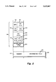
- FIG. 2 is a block diagram showing an ATM cell
- FIG. 3 is a block diagram showing aa ATM cell which includes a credit field.
- FIG. 4 is a block diagram showing memory management of a credit-based ATM flow control mechanism in accordance with one embodiment of the present invention
- an exemplary asynchronous transfer mode (ATM) local area network (LAN) 10 is shown to include four stations labeled as 12, 14, 16, and 18, respectively.
- the ATM LAN 10 is also shown to include two ATM switches labeled as 20 and 22, respectively.
- An ATM adapter resides in each of the stations 12, 14, 16, and 18.
- station 12 is transmitting packets for station 16
- the ATM adapter in station 12 is involved in segmenting the packets into cells, and affixing the appropriate fields in a cell header (of FIG. 2 and FIG. 3).
- the ATM adapter in station 16 is involved in reassembling the cells received into a complete packet and delivering the packet to station 16.
- Control of the ATM LAN 10 resides in the ATM switches 20 and 22, which route messages between stations and control access in the event of congestion.
- the station 12 may send a cell over a line 24 to ATM switch 20 through port 26.
- ATM switch 20 will route the cell to a destination, Station 16, for example, according to a VCI/VPI in an ATM cell header (more fully described with reference to FIG. 2 and FIG. 3).
- each port 26 is dedicated to one station 12, other stations (14 for example) do not have to contend for access to the ATM switch 20.
- the station 12 has full access to the line 24 regardless of the activity of other stations with other such connections. For example, if a 5 Mb file is being transmitted from station 12 to station 16, it can move to the ATM switch 20 in a continuous burst at the full channel rate, instead of sharing the communication link in the other stations and having intervening frames from other stations as with other LANs, such as Ethernet, Token Ring, and Fiber Distributed Data Interface (FDDI) LANs.
- FDDI Fiber Distributed Data Interface
- Each message in the ATM LAN 10 is comprised of one or more fixed length units of data called ATM cells.
- an ATM cell 30 is shown to be 53 bytes long.
- the ATM cell 30 is typically divided into a 5-byte header 32 and a 48-byte information field 34.
- the 5-byte header 32 contains several fields 36. Specifically, a first byte contains a generic flow control (GFC) field 38 and part of a virtual path identifier (VPI) field 40.
- a second byte contains another part of the VPI field 42 and part of a virtual channel identifier (VCI) field 44.
- a third byte contains another part of the VCI field 46.
- a fourth byte contains the remaining part of the VCI field 48, a payload type identifier (PTI) field 50, and a cell loss priority field (CLP) 52.
- a fifth byte contains a header error check 54.
- the address of the ATM cell 30 is contained in the fields labeled VPI (40 and 42) and VCI (44, 46, and 48). This two-part identification allows the ATM LAN 10 (of FIG. 1) to route data contained in the information field 34 between locations while maintaining the identity of individual circuits within a trunk.
- the header 62 is 5 bytes long and contains several fields 64. Specifically, a first byte contains a GFC field 66 and a part of credit virtual circuit identifier (credit VCI) 68. A second byte contains another part of the credit VCI 70. A third byte contains part of a destination VCI 72. A fourth byte contains a remaining part of the destination VCI 74, a PTI field 76, and a CLP field 78. A fifth byte contains a header error check field 80.
- a first byte contains a GFC field 66 and a part of credit virtual circuit identifier (credit VCI) 68.
- a second byte contains another part of the credit VCI 70.
- a third byte contains part of a destination VCI 72.
- a fourth byte contains a remaining part of the destination VCI 74, a PTI field 76, and a CLP field 78.
- a fifth byte contains a header error check field 80.
- the ATM LAN 10 breaks packets into fixed-size (53 bytes) cells before they are transmitted.
- the challenge with small cells is that loss of any single cell destroys the entire packet of which it is a part.
- a 9180 byte packet is broken into 192 ATM cells (48 bytes of data per ATM cell).
- the loss of any one cell because of congestion in the network (communication link or intermediate switches) requires retransmission of all 192 ATM cells.
- the loss of cells, and the corollary loss of packets is bad enough, but more significant impact is that these lost packets are now retransmitted into the congested network, causing more congestion and more cell loss.
- This snowball effect can lead to a state of the network called "throughput collapse.” Most of the newly transmitted packets are thus destined for congestion and discard.
- Each application can have a virtual circuit (VC) established through each ATM link and ATM adapter with guaranteed bandwidth. This can avoid cell loss but only at a very high cost. For example, when 100 stations set up VCs to a server using a 155 Mbps link, each VC will have only about 1.5 Mbps bandwidth to access the server. While this is suitable for applications generating a steady flow of information, it is generally not true of data applications to generate cells at such a rate. Data applications generate cells in a bursty fashion, and hence leave some of the above allocated bandwidth unusable. This leads to inefficient use of the link.
- VC virtual circuit
- flow control a means of controlling the flow of cells (known as flow control) based on a link-by-link system of control was designed. This design is based on credits and buffers per VC.
- an exemplary credit-based ATM flow control system is illustrated.
- a transmitter portion 102 of an upstream ATM switch 100 is sending an ATM cell 104 on virtual circuit identifier (VCI) 106.
- VCI virtual circuit identifier
- the credit field 108 in ATM cell 104 is carrying a credit for a transmitter portion 110 of a downstream ATM adapter 112 for VCI 114.
- a "credit" is simply an okay to send one or more ATM cells on a VCI, with the assurance that the cell(s) will have a buffer at the remote end and hence not experience loss.
- the downstream ATM adapter 112 when the downstream ATM adapter 112 moves the ATM cell 104 of VCI 106 from its local memory 116 from a receiver portion 118 and into a host memory 120, the downstream ATM adapter 112 generates a credit 122 for the transmitter portion 102 of the upstream ATM switch 100 to allow transmission of a new ATM cell (not shown) on VCI 106.
- This credit for the transmitter portion 102 can be carried by any ATM cell transmitted by the transmitter portion 110 of the downstream ATM adapter 112 to a receiver portion 124 of the upstream ATM switch 100.
- a credit 126 for VCI 106 is carried on an ATM cell 128 on VCI 114.
- the receiver portion 124 of the upstream ATM switch 100 receives the ATM cell 128 from the transmitter portion 110 of the downstream ATM adapter 112 and stores it in its local memory 130.
- the upstream ATM switch 100 uses the credit 126 to transmit another cell on VCI 106.
- the upstream ATM switch 100 moves the ATM cell 128 from its local memory 130 to one of its output ports 132, the upstream ATM switch 100 generates a credit 134 for VCI 114, which will be carried by any ATM cell transmitted towards the downstream ATM adapter 112.
- each transmit VC In order to be able to maintain a full link speed for each virtual circuit, it is necessary to provide each transmit VC with an initial fixed number of credits. This number should be large enough to ensure that the transmitter portion 102 of an upstream ATM switch 100 will not stop transmitting before the upstream ATM switch 100 receives a first credit from the transmitter portion 110 of the downstream ATM adapter 112. Thus, the receiver portion 118 of the downstream ATM adapter 112 should have enough local memory 116 to accommodate a number of cells corresponding to the transmission of initial credits given to the upstream ATM switch 100.
- the credit VCI field (68 and 70) of each arriving ATM cell 60 identifies the transmit virtual circuit (VC) which is given a new credit for transmission from a transmitter to a receiver. After moving out this newly arrived ATM cell 60 from its memory buffer, the receiver should return a credit to the sender. The virtual circuit whose credit is returned is for the one that this ATM cell 60 was sent on, i.e., the value of the VCI field (72 and 74). Transmitting or receiving credits may be done one credit per an ATM cell 60, or in a scheme that may provide a plurality of credits per an ATM cell 60.
- An arriving ATM cell 60 may be a null cell. This is indicated by a destination VCI (72 and 74) having a value of zero. In this case, the ATM cell 60 is ignored and no credit is sent back. However, a null ATM cell 60 may carry a credit, i.e., a non-zero VCI (68 and 70). A transmitted ATM cell 60 is not carrying any credits if its credit VCI (68 and 70) is equal to zero.
- the local memory 116 (of FIG. 4) of the receiver portion 118 (of FIG. 4) of the downstream ATM adapter 112 (of FIG. 4) is divided into two buffer pools 150.
- One of the buffer pools 150 is referred to as a static pool 152.
- the static pool 152 is used to accommodate the reception of ATM cells from all VCs, as long as these VCs share a positive balance of credits.
- the size of the static pool 152 is given the limit on the minimum memory size the downstream ATM adapter 112 needs to have as buffering in its local memory 116.
- the initial size of the static pool 152 is determined by taking the sum across all VCs of the number of VCs times the number of initial credits per VC.
- the number of initial credits for each VC is typically set to be sufficient for the VC to flow at the full link rate, and the credit for the first cell sent in a given burst of cells has its credits returned to the sended before the sender exhausts its "initial credits," if there is no contention from any other VC on the link.
- This static pool 152 includes empty ATM cell buffers that are used to store ATM cells arriving from the transmitter portion 102 of the upstream ATM switch 100 even when the transmitter portion 110 of the downstream adapter 112 stops sending credits for those received ATM cells due to congestion.
- the transmitter portion 102 of the upstream ATM switch 100 will stop sending cells to the downstream ATM adapter 112 only when it has used up all of its credits which were initially given.
- One of the buffer pools 150 is referred to as a dynamic pool 154.
- the dynamic pool 154 is used to reassemble the packets.
- receiver portion 118 of the downstream ATM adapter 112 has nine queues 160 for packet reassembly implemented in its local memory 116.
- the nine queues 160 consist of one active queue 162 and eight stalled queues labeled as 164-0, 164-1, 164-2, 164-3, 164-4, 164-5, 164-6, and 164-7, respectively.
- the downstream ATM adapter 112 When the downstream ATM adapter 112 receives in its receiver portion 118 a first ATM cell 104 for a certain VC (VC 106 for example), the downstream ATM adapter 112 has two choices. The downstream ATM adapter 112 may enqueue this VC 106 into the active queue 162, or the downstream ATM adapter 112 may enqueue this VC 106 into one of the eight stalled queues (for example, if a packet has to be placed in a stalled queue, the queue that is chosen to be placed on is based on the VC that it is received on).
- the transmitter portion 110 of the downstream ATM adapter 112 will always return credits to a VC which is placed in the active queue 162. As long as the VC is queued in the stalled queue (164-0, for example), credits will be kept in the downstream ATM adapter 112 and will be returned to the upstream switch 100 only when the VC is dequeued from stalled queue 164-0 and enqueued into the active queue 162. The conditions by which a VC queued in a stalled queue 164-0 is moved to the active queue 162 will be discussed below.
- the downstream ATM adapter has a receive cell buffers pool 150 (of FIG. 5) divided into a dynamic pool 154 and a static pool 152.
- the dynamic pool 154 is used when the VC is in the active queue 162 and the static pool 152 is used when the VC is in the stalled queue.
- the downstream adapter 112 sends an initial credit balance so that the upstream adapter 112 can start sending cells.
- This credit balance comes from the static pool 152, which must be large enough to cover all of the credit balances for all the potentially simultaneous open connections.
- the local memory 116 of the downstream ATM adapter 112 maintains a list of supported VCs in a descriptor entry called VC entry (VCE) 136.
- VCE entry 136 contains information about the reassembled packet.
- the VCE entry 136 also contains two pointers which are used to form a doubly linked list of VCEs (oldest VC first, youngest VC last) and by which either the active queue 162 or the stalled queue (164-0 through 164-7) is constructed.
- an exemplary doubly linked list queue of VCEs 180 is shown to include a head 182, a tail 184, and a counter entry 186.
- the counter entry 186 is used to indicate how many VCEs are located in the exemplary doubly linked list queue of VCEs 180.
- three VCEs entries are shown labeled as 188, 190, and 192, respectively. After the conditions for the VCE 188 are met (more fully described below), it can be moved to the active queue 162. Only then will the conditions for the next VCE 190 in queue 180 be examined with regard to moving it to the actice queue.
- the VC may be in the stalled queue, 164-0 for example, or not queued at all. If the VC is not queued, it will be queued as the youngest element 192, for example, in either the active queue 162 or the stalled queue 164-0.
- the stalled queues are selected according to a first in first out (FIFO) arbitration scheme, i.e., the oldest VCE 188 is dequeued from the selected stalled queue and is enqueued as the youngest element in the active queue 162.
- FIFO first in first out
- Each of the VCEs 186, 188, 190, and 192 contain three indicator variables.
- a first indicator variable is referred to as a VC -- queue variable and may be assigned one of three values.
- a VC -- queue variable with a value of "00" indicates that the VC is not queued at all.
- a VC -- queue variable with a value of "01” indicates that the VC is queued in a stalled queue.
- a VC -- queue variable with a value of "10” indicates that the VC is queued in the active queue.
- the downstream ATM adapter 112 will only return credits 122 to the upstream ATM switch 100 if the VC is queued to the active queue 162, i.e., that the VC -- queue variable has a value of "10".
- a second indicator variable is referred to as a VC -- credit -- count variable.
- the VC -- credit -- count variable counts the number of ATM cells which the downstream ATM adapter 112 has received for this VC while it was queued in the stalled queue.
- the value of the VC -- credit -- count variable is the number of credits the downstream ATM adapter 112 did not return for that VC. These credits will ultimately be returned when the VC transitions into the active queue.
- a third indicator variable is referred to as a VC -- count variable.
- the VC -- count variable represents the number of ATM cells received which belong to the same packet, which is currently being assembled.
- the three indicator variables i.e., VC -- queue, VC -- credit -- count, and VC -- count, are used in the following manner.
- the downstream ATM adapter 112 For each queue, the downstream ATM adapter 112 counts the exact number of buffers used from both the dynamic pool 154 and the static pool 152. The downstream ATM adapter 112 also keeps a "commitment" counter which counts how many cell buffers the downstream ATM adapter 112 is committed for. Before each packet is enqueued into the active queue 162, the downstream ATM adapter 112 checks if it has enough buffering in its local memory 116 for receiving the maximum packet length possible on that queue. If the downstream ATM adapter 112 has enough buffering in its local memory 116, it "marks" these buffers as committed and treats them as being utilized.
- a first point in time is when the packet is moved into the active queue 162.
- the downstream ATM adapter 112 commits to acomadate for the maximum packet length on this queue.
- a second point in time is when the packet reassembly has been completed but not sent out to host memory.
- the downstream ATM adapter 112 adjusts a committed buffers counter so that it reflects the actual packet size if the received packet size is less than the maximum packet size possible on this VC.
- the committed buffers counter is adjusted by substracting the value [(Max -- pkt -- size)-(the -- size -- of -- the -- received -- pkt)].
- a third point in time when the downstream ATM adapter 112 activate the next VC is when the packet has completed reassembly and is stored to host memory.
- the downstream ATM adapter 112 frees up the cell buffers in its local memory 116 for that packet.
- the free buffers counter is adjusted, i.e., incremented, with the -- size -- of -- the -- received -- pkt.
- the downstream ATM adapter 112 will decide to activate a VC according to the difference between the free buffers counter, and the committed, the static and the max -- pkt -- size buffers.
- Activating a VC refers to the process of enqueuing a VC to the active queue 162.
- a VC may be activated after it is dequeued from the stalled queue, or if the first ATM cell of the packet is received and the VC is idle, and there is enough buffers in the free dynamic memory pool to accomadate a maximum size packet from that VC.
- a first variable is referred to as a free -- buffers variable.
- the free -- buffers variable contains a value which represents the sum of the dynamic pool 154 buffers and the static pool 152 buffers for all VCs destined to this queue.
- a second variable is referred to as a static -- buffers variable.
- the static -- buffers variable contains a value which represents the number of static buffers pool 152 across all VCs destined to this queue.
- a third variable is referred to as a committed -- buffers variable.
- the committed -- buffers variable contains a value which represents the number of ATM cell buffers the downstream ATM adapter has committed to. This value is initialized to zero and for each packet moved into the active queue 162, the committed -- buffers variable is incremented to accomadate for the maximum packet length possible on this VC, i.e., max -- pkt -- len.
- a fourth variable is referred to as a max -- pkt -- len variable.
- the max -- pkt -- len variable contains a value which represents the maximum packet length on a group of VCs destined to this queue.
- Buffer and credit management in the downstream ATM adapter 112 operates according to the following rules:
- the credit return mechanism 122 (of FIG. 4) of the downstream ATM adapter 112 utilizes two first-in-first-out (FIFO) queues.
- a first FIFO is referred to as a credit delayed FIFO 200.
- the credit delayed FIFO 200 is used to store credits that are delayed. Only one credit may be returned in one ATM cell.
- the downstream ATM adapter 112 returns credits from an activate FIFO 202 (discussed below)
- the flow of returning credits for VCs in the active queue 162 are temporarily put in the credit delayed FIFO 200.
- the credit delayed FIFO 200 holds the VC number as the credit.
- the activate FIFO 202 is used to store credits that are scheduled to be returned when the VC was moved from the stalled queue 164 to the active queue 162. All the credits that were placed in the stalled queue 164 are put into one entry in the activate FIFO 202. An entry of the activate FIFO 202 holds the VC number and VC -- credit -- count values.
- the downstream ATM adapter 112 will use an arbiter to determine from which FIFO to return credits.
- the arbiter uses a dynamic 1-of-N arbitration (1 from activate FIFO 202, N from delayed FIFO 200), where N is increasing as the number of entries in the delayed FIFO 200 is increasing. This gives to the delayed FIFO 200 a fair share of the returned credit bandwidth.
- the dynamic 1-of-N arbitration works as follows. As long as the delayed FIFO 200 has less than or equal to 56 credits stored, for every credit returned from the activate FIFO 202, 32 credits will be returned from the delayed FIFO 200. As long as the delayed FIFO 200 has more than 56 and less than or equal to 4K credits stored, for every credit will be returned from the activate FIFO 202, 64 credits will be returned from the delayed FIFO 200. As long as the delayed FIFO 200 has more than 4K and less than or equal to 8K credits stored, for every credit returned from the activate FIFO 202, 128 credits will be returned from the delayed FIFO 200.
- the delayed FIFO 200 has more than 8K and less than or equal to 16K credits, for every credit returned from the activate FIFO 202, 256 credits will be returned from the delayed FIFO 200. If there are more than 16K credits in the delayed FIFO 200, credits will return only from the delayed FIFO 200.
Abstract
Description
______________________________________
Rule 1 (first ATM cell)
For a first ATM cell received do:
If VC.sub.-- queue = 0 then:
 If (free.sub.-- buffers - committed.sub.-- buffers - max.sub.-- pkt.sub.-
- len) >
 static buffers do:
 enqueue the VC to active queue
 committed.sub.-- buffers committed.sub.-- buffers + max.sub.-- pkt.sub.--
 len
 else do:
 enqueue the VC to the stalled queue
Rule 2 (Every ATM cell)
For every ATM cell do:
 free.sub.-- buffers = free.sub.-- buffers - 1
 VC.sub.-- count = VC.sub.-- count + 1
 If the VC is in the active queue do:
 committed buffers = committed.sub.-- buffers - 1
 If the VC is in the stalled queue do:
 static.sub.-- buffers = static buffers - 1
 VC.sub.-- credit.sub.-- count = VC.sub.-- credit.sub.-- count + 1
Rule 3 (Last ATM Cell)
After the downstream ATM adapter 112 receives the last
ATM cell do:
 if the VC is in the active queue 162, do:
 committed.sub.-- buffers = committed.sub.-- buffers - max.sub.--
pkt.sub.-- len
 + VC.sub.-- count
 VC.sub.-- count = 0
Dequeue the VC from the active queue
VC.sub.-- Count = 0
Rule 4 (when storing a packet in host memory)
After the downstream ATM adapter 112 stores a packet in
host memory, the number of cell buffers freed, i.e., the
actual packet length, are added to free.sub.-- buffers.
Rule 5 (When to activate a stalled queue)
If the packet has completed reassembly the downstream ATM
adapter can activate a stalled VC if:
 free.sub.-- buffers - committed.sub.-- buffers - (maximum value of
 VC.sub.-- Credit .sub.-- count) > static.sub.-- buffers
If the packet has not completed reassembly, the
downstream ATM adapter can activate a VC if:
 free.sub.-- buffers - committed.sub.-- buffers - (maximum value of
 VC.sub.-- credit.sub.-- count) - (max.sub.-- pkt.sub.-- len - VC.sub.--
count))>
 static.sub.-- buffers
Rule 6 (When activating a stalled queue)
To activate a VC, do:
 static.sub.-- buffers = static.sub.-- buffers + VC.sub.-- credit.sub.--
count
 Dequeue the VC from stalled queue
If the packet has not completed reassembly do:
 committed.sub.-- buffers = committed.sub.-- buffers + max.sub.--
pkt.sub.-- len
- VC.sub.-- count
______________________________________
Claims (26)
Priority Applications (1)
| Application Number | Priority Date | Filing Date | Title |
|---|---|---|---|
| US08/269,984 US5633867A (en) | 1994-07-01 | 1994-07-01 | Local memory buffers management for an ATM adapter implementing credit based flow control |
Applications Claiming Priority (1)
| Application Number | Priority Date | Filing Date | Title |
|---|---|---|---|
| US08/269,984 US5633867A (en) | 1994-07-01 | 1994-07-01 | Local memory buffers management for an ATM adapter implementing credit based flow control |
Publications (1)
| Publication Number | Publication Date |
|---|---|
| US5633867A true US5633867A (en) | 1997-05-27 |
Family
ID=23029408
Family Applications (1)
| Application Number | Title | Priority Date | Filing Date |
|---|---|---|---|
| US08/269,984 Expired - Fee Related US5633867A (en) | 1994-07-01 | 1994-07-01 | Local memory buffers management for an ATM adapter implementing credit based flow control |
Country Status (1)
| Country | Link |
|---|---|
| US (1) | US5633867A (en) |
Cited By (63)
| Publication number | Priority date | Publication date | Assignee | Title |
|---|---|---|---|---|
| WO1997042577A1 (en) * | 1996-05-09 | 1997-11-13 | Maker Communications, Inc. | Asynchronous transfer mode cell processing system with cell buffer space gathering |
| US5748613A (en) * | 1996-03-29 | 1998-05-05 | Hewlett-Packard Company | Communication pacing method |
| US5778180A (en) * | 1995-11-06 | 1998-07-07 | Sun Microsystems, Inc. | Mechanism for reducing data copying overhead in protected memory operating systems |
| US5794025A (en) * | 1996-05-09 | 1998-08-11 | Maker Communications, Inc. | Method and device for performing modulo-based arithmetic operations in an asynchronous transfer mode cell processing system |
| US5825748A (en) * | 1997-04-08 | 1998-10-20 | International Business Machines Corporation | Credit-based flow control checking and correction system |
| EP0886454A2 (en) * | 1997-06-20 | 1998-12-23 | Digital Equipment Corporation | Method and apparatus to expand an on-chip fifo into local memory |
| US5870628A (en) * | 1996-06-11 | 1999-02-09 | International Business Machines Corporation | Adaptor for receiving and processing asynchronous transfer mode cells within a computer network |
| WO1999011037A1 (en) * | 1997-08-29 | 1999-03-04 | Extreme Networks | Protocol for communicating data between packet forwarding devices via an intermediate network interconnect device |
| US5901147A (en) * | 1996-08-30 | 1999-05-04 | Mmc Networks, Inc. | Apparatus and methods to change thresholds to control congestion in ATM switches |
| US5917828A (en) * | 1997-01-03 | 1999-06-29 | Ncr Corporation | ATM reassembly controller and method |
| US5920698A (en) * | 1997-01-06 | 1999-07-06 | Digital Equipment Corporation | Automatic detection of a similar device at the other end of a wire in a computer network |
| US6014367A (en) * | 1997-04-25 | 2000-01-11 | Mmc Networks, Inc | Method for weighted fair queuing for ATM cell scheduling |
| US6023471A (en) * | 1997-10-07 | 2000-02-08 | Extreme Networks | Network interconnect device and protocol for communicating data among packet forwarding devices |
| US6026090A (en) * | 1997-11-14 | 2000-02-15 | Fore System, Inc. | Method and system for receiving ATM cells from an ATM network by a host |
| US6041059A (en) * | 1997-04-25 | 2000-03-21 | Mmc Networks, Inc. | Time-wheel ATM cell scheduling |
| US6044406A (en) * | 1997-04-08 | 2000-03-28 | International Business Machines Corporation | Credit-based flow control checking and correction method |
| US6047000A (en) * | 1997-07-24 | 2000-04-04 | The Hong Kong University Of Science & Technology | Packet scheduling system |
| US6088736A (en) | 1995-07-19 | 2000-07-11 | Fujitsu Network Communications, Inc. | Joint flow control mechanism in a telecommunications network |
| US6128303A (en) * | 1996-05-09 | 2000-10-03 | Maker Communications, Inc. | Asynchronous transfer mode cell processing system with scoreboard scheduling |
| US6128278A (en) * | 1996-08-30 | 2000-10-03 | Mmc Networks, Inc. | Cell queuing in ATM switches |
| US6151303A (en) * | 1996-06-06 | 2000-11-21 | Nec Corporation | Method of asynchronous transfer mode (ATM) switching and an ATM switching equipment |
| US6169748B1 (en) * | 1998-10-27 | 2001-01-02 | Fujitsu Network Communications, Inc. | Frame based quality of service |
| US6185223B1 (en) * | 1996-12-04 | 2001-02-06 | Conexant Systems, Inc. | Apparatus and method for providing fire wall protection for systems in communication with an a synchronous transfer mode system |
| US6307860B1 (en) | 1998-04-03 | 2001-10-23 | Mmc Networks, Inc. | Systems and methods for data transformation and transfer in networks |
| US6330584B1 (en) | 1998-04-03 | 2001-12-11 | Mmc Networks, Inc. | Systems and methods for multi-tasking, resource sharing and execution of computer instructions |
| US20020004842A1 (en) * | 2000-06-30 | 2002-01-10 | Kanad Ghose | System and method for fast, reliable byte stream transport |
| US6347337B1 (en) * | 1999-01-08 | 2002-02-12 | Intel Corporation | Credit based flow control scheme over virtual interface architecture for system area networks |
| US6396807B1 (en) * | 1997-11-18 | 2002-05-28 | Thomson-Csf | Method for the control of flows of digital information |
| US6411627B1 (en) * | 1994-07-25 | 2002-06-25 | Curtin University Of Technology | Switching protocol providing controlled access to available asynchronous network service |
| US6442170B1 (en) | 1997-01-06 | 2002-08-27 | Enterasys Networks, Inc. | Adaptive addressing filtering |
| US20020159385A1 (en) * | 2001-04-26 | 2002-10-31 | Susnow Dean S. | Link level packet flow control mechanism |
| US6477143B1 (en) | 1998-01-25 | 2002-11-05 | Dror Ginossar | Method and apparatus for packet network congestion avoidance and control |
| US6480489B1 (en) * | 1999-03-01 | 2002-11-12 | Sun Microsystems, Inc. | Method and apparatus for data re-assembly with a high performance network interface |
| US6504821B2 (en) * | 1996-06-12 | 2003-01-07 | At&T Corp. | Flexible bandwidth negotiation for the block transfer of data |
| US20030016683A1 (en) * | 1999-12-10 | 2003-01-23 | George William R. | Fibre channel credit extender and repeater |
| WO2003019393A1 (en) * | 2001-08-24 | 2003-03-06 | Intel Corporation | A general intput/output architecture, protocol and related methods to implement flow control |
| US20030131179A1 (en) * | 2001-08-24 | 2003-07-10 | Jasmin Ajanovic | General input/output architecture, protocol and related methods to provide isochronous channels |
| US6618354B1 (en) * | 1998-03-13 | 2003-09-09 | Hewlett-Packard Development Company, L.P. | Credit initialization in systems with proactive flow control |
| US20030179748A1 (en) * | 2000-06-05 | 2003-09-25 | George William R. | Hardware-enforced loop-level hard zoning for fibre channel switch fabric |
| US6643265B1 (en) * | 2000-05-10 | 2003-11-04 | 3Com Corporation | Apparatus for and method of releasing stuck virtual circuits in an asynchronous transfer mode network |
| US20030223444A1 (en) * | 2002-05-31 | 2003-12-04 | International Business Machines Corporation | Method and apparatus for implementing multiple credit levels over multiple queues |
| US20040085978A1 (en) * | 2002-11-04 | 2004-05-06 | Bly Keith Michael | System and method for prioritizing and queuing traffic |
| US6747949B1 (en) * | 1999-05-21 | 2004-06-08 | Intel Corporation | Register based remote data flow control |
| US20040120336A1 (en) * | 2002-12-24 | 2004-06-24 | Ariel Hendel | Method and apparatus for starvation-free scheduling of communications |
| US20040141521A1 (en) * | 1999-07-02 | 2004-07-22 | Ancor Communications, Inc. | High performance switch fabric element and switch systems |
| US6771647B1 (en) * | 1998-10-06 | 2004-08-03 | Stmicroelectronics Limited | Data transfer |
| US20040199916A1 (en) * | 1998-04-03 | 2004-10-07 | Alexander Joffe | Systems and methods for multi-tasking, resource sharing, and execution of computer instructions |
| US6810031B1 (en) * | 2000-02-29 | 2004-10-26 | Celox Networks, Inc. | Method and device for distributing bandwidth |
| US20040264486A1 (en) * | 2003-05-29 | 2004-12-30 | Covaro Networks, Inc. | System and method for time-based scheduling |
| US6944173B1 (en) * | 2000-03-27 | 2005-09-13 | Hewlett-Packard Development Company, L.P. | Method and system for transmitting data between a receiver and a transmitter |
| US20050228900A1 (en) * | 2004-04-08 | 2005-10-13 | David Stuart | Credit recovery in a credit based flow control system |
| US20050286544A1 (en) * | 2004-06-25 | 2005-12-29 | Kitchin Duncan M | Scalable transmit scheduling architecture |
| US20060050639A1 (en) * | 2004-09-03 | 2006-03-09 | David Stuart | Credit-based method and apparatus for controlling data communications |
| US20060056292A1 (en) * | 2004-09-16 | 2006-03-16 | David Mayhew | Fast credit system |
| US20060075161A1 (en) * | 2004-10-01 | 2006-04-06 | Grijalva Oscar J | Methd and system for using an in-line credit extender with a host bus adapter |
| US20060140364A1 (en) * | 2004-12-28 | 2006-06-29 | Kabushiki Kaisha Toshiba | Electronic device and its control method |
| US20070274215A1 (en) * | 2006-05-23 | 2007-11-29 | International Business Machines Corporation | Method and a system for flow control in a communication network |
| US20080095152A1 (en) * | 2000-06-05 | 2008-04-24 | Qlogic Switch Products, Inc. | Hardware-enforced loop and npiv hard zoning for fibre channel switch fabric |
| US7535842B1 (en) * | 2004-04-09 | 2009-05-19 | Nortel Networks Limited | Method and system for merging bandwidth in multiplexing flows |
| US7930377B2 (en) | 2004-04-23 | 2011-04-19 | Qlogic, Corporation | Method and system for using boot servers in networks |
| US20160124883A1 (en) * | 2014-10-31 | 2016-05-05 | Texas Instruments Incorporated | Multicore Bus Architecture With Non-Blocking High Performance Transaction Credit System |
| US9606245B1 (en) | 2015-03-24 | 2017-03-28 | The Research Foundation For The State University Of New York | Autonomous gamma, X-ray, and particle detector |
| US9836424B2 (en) | 2001-08-24 | 2017-12-05 | Intel Corporation | General input/output architecture, protocol and related methods to implement flow control |
Citations (2)
| Publication number | Priority date | Publication date | Assignee | Title |
|---|---|---|---|---|
| US5483526A (en) * | 1994-07-20 | 1996-01-09 | Digital Equipment Corporation | Resynchronization method and apparatus for local memory buffers management for an ATM adapter implementing credit based flow control |
| US5519698A (en) * | 1992-05-20 | 1996-05-21 | Xerox Corporation | Modification to a reservation ring mechanism for controlling contention in a broadband ISDN fast packet switch suitable for use in a local area network |
-
1994
- 1994-07-01 US US08/269,984 patent/US5633867A/en not_active Expired - Fee Related
Patent Citations (2)
| Publication number | Priority date | Publication date | Assignee | Title |
|---|---|---|---|---|
| US5519698A (en) * | 1992-05-20 | 1996-05-21 | Xerox Corporation | Modification to a reservation ring mechanism for controlling contention in a broadband ISDN fast packet switch suitable for use in a local area network |
| US5483526A (en) * | 1994-07-20 | 1996-01-09 | Digital Equipment Corporation | Resynchronization method and apparatus for local memory buffers management for an ATM adapter implementing credit based flow control |
Non-Patent Citations (3)
| Title |
|---|
| ATM in Private Networking, by Anthony Alles, Product Line Manager, Hughes Lan Systems, Interop 92 Version. * |
| IEEE Spectrum, Feb. 1994, pp. 42 45, by James Lane, TRAC Associates Inc., ATM knits voice, data on any net . * |
| IEEE Spectrum, Feb. 1994, pp. 42-45, by James Lane, TRAC Associates Inc., `ATM knits voice, data on any net`. |
Cited By (124)
| Publication number | Priority date | Publication date | Assignee | Title |
|---|---|---|---|---|
| US6411627B1 (en) * | 1994-07-25 | 2002-06-25 | Curtin University Of Technology | Switching protocol providing controlled access to available asynchronous network service |
| US6167452A (en) | 1995-07-19 | 2000-12-26 | Fujitsu Network Communications, Inc. | Joint flow control mechanism in a telecommunications network |
| US6088736A (en) | 1995-07-19 | 2000-07-11 | Fujitsu Network Communications, Inc. | Joint flow control mechanism in a telecommunications network |
| US5778180A (en) * | 1995-11-06 | 1998-07-07 | Sun Microsystems, Inc. | Mechanism for reducing data copying overhead in protected memory operating systems |
| US5748613A (en) * | 1996-03-29 | 1998-05-05 | Hewlett-Packard Company | Communication pacing method |
| US6359891B1 (en) | 1996-05-09 | 2002-03-19 | Conexant Systems, Inc. | Asynchronous transfer mode cell processing system with scoreboard scheduling |
| US5860148A (en) * | 1996-05-09 | 1999-01-12 | Maker Communications, Inc. | Asynchronous transfer mode cell processing system with cell buffer space gathering |
| US5794025A (en) * | 1996-05-09 | 1998-08-11 | Maker Communications, Inc. | Method and device for performing modulo-based arithmetic operations in an asynchronous transfer mode cell processing system |
| US6128303A (en) * | 1996-05-09 | 2000-10-03 | Maker Communications, Inc. | Asynchronous transfer mode cell processing system with scoreboard scheduling |
| WO1997042577A1 (en) * | 1996-05-09 | 1997-11-13 | Maker Communications, Inc. | Asynchronous transfer mode cell processing system with cell buffer space gathering |
| US6151303A (en) * | 1996-06-06 | 2000-11-21 | Nec Corporation | Method of asynchronous transfer mode (ATM) switching and an ATM switching equipment |
| US5870628A (en) * | 1996-06-11 | 1999-02-09 | International Business Machines Corporation | Adaptor for receiving and processing asynchronous transfer mode cells within a computer network |
| US6504821B2 (en) * | 1996-06-12 | 2003-01-07 | At&T Corp. | Flexible bandwidth negotiation for the block transfer of data |
| US5901147A (en) * | 1996-08-30 | 1999-05-04 | Mmc Networks, Inc. | Apparatus and methods to change thresholds to control congestion in ATM switches |
| US6128278A (en) * | 1996-08-30 | 2000-10-03 | Mmc Networks, Inc. | Cell queuing in ATM switches |
| US6185223B1 (en) * | 1996-12-04 | 2001-02-06 | Conexant Systems, Inc. | Apparatus and method for providing fire wall protection for systems in communication with an a synchronous transfer mode system |
| US5917828A (en) * | 1997-01-03 | 1999-06-29 | Ncr Corporation | ATM reassembly controller and method |
| US5920698A (en) * | 1997-01-06 | 1999-07-06 | Digital Equipment Corporation | Automatic detection of a similar device at the other end of a wire in a computer network |
| US6442170B1 (en) | 1997-01-06 | 2002-08-27 | Enterasys Networks, Inc. | Adaptive addressing filtering |
| US5825748A (en) * | 1997-04-08 | 1998-10-20 | International Business Machines Corporation | Credit-based flow control checking and correction system |
| US6044406A (en) * | 1997-04-08 | 2000-03-28 | International Business Machines Corporation | Credit-based flow control checking and correction method |
| US6041059A (en) * | 1997-04-25 | 2000-03-21 | Mmc Networks, Inc. | Time-wheel ATM cell scheduling |
| US6014367A (en) * | 1997-04-25 | 2000-01-11 | Mmc Networks, Inc | Method for weighted fair queuing for ATM cell scheduling |
| US6078565A (en) * | 1997-06-20 | 2000-06-20 | Digital Equipment Corporation | Method and apparatus to expand an on chip FIFO into local memory |
| EP0886454A2 (en) * | 1997-06-20 | 1998-12-23 | Digital Equipment Corporation | Method and apparatus to expand an on-chip fifo into local memory |
| EP0886454A3 (en) * | 1997-06-20 | 2000-09-20 | Compaq Computer Corporation | Method and apparatus to expand an on-chip fifo into local memory |
| US6047000A (en) * | 1997-07-24 | 2000-04-04 | The Hong Kong University Of Science & Technology | Packet scheduling system |
| WO1999011037A1 (en) * | 1997-08-29 | 1999-03-04 | Extreme Networks | Protocol for communicating data between packet forwarding devices via an intermediate network interconnect device |
| US5974467A (en) * | 1997-08-29 | 1999-10-26 | Extreme Networks | Protocol for communicating data between packet forwarding devices via an intermediate network interconnect device |
| US6023471A (en) * | 1997-10-07 | 2000-02-08 | Extreme Networks | Network interconnect device and protocol for communicating data among packet forwarding devices |
| US6026090A (en) * | 1997-11-14 | 2000-02-15 | Fore System, Inc. | Method and system for receiving ATM cells from an ATM network by a host |
| US6396807B1 (en) * | 1997-11-18 | 2002-05-28 | Thomson-Csf | Method for the control of flows of digital information |
| US6477143B1 (en) | 1998-01-25 | 2002-11-05 | Dror Ginossar | Method and apparatus for packet network congestion avoidance and control |
| US6618354B1 (en) * | 1998-03-13 | 2003-09-09 | Hewlett-Packard Development Company, L.P. | Credit initialization in systems with proactive flow control |
| US20030193892A1 (en) * | 1998-03-13 | 2003-10-16 | Sharma Debendra Das | Credit initialization in systems with proactive flow control |
| US6307860B1 (en) | 1998-04-03 | 2001-10-23 | Mmc Networks, Inc. | Systems and methods for data transformation and transfer in networks |
| US9110714B2 (en) | 1998-04-03 | 2015-08-18 | Alexander Joffe | Systems and methods for multi-tasking, resource sharing, and execution of computer instructions |
| US20040199916A1 (en) * | 1998-04-03 | 2004-10-07 | Alexander Joffe | Systems and methods for multi-tasking, resource sharing, and execution of computer instructions |
| US7590785B2 (en) | 1998-04-03 | 2009-09-15 | Applied Micro Circuits Corporation | Systems and methods for multi-tasking, resource sharing, and execution of computer instructions |
| US20090282408A1 (en) * | 1998-04-03 | 2009-11-12 | Alexander Joffe | Systems and methods for multi-tasking, resource sharing, and execution of computer instructions |
| US7055151B1 (en) | 1998-04-03 | 2006-05-30 | Applied Micro Circuits Corporation | Systems and methods for multi-tasking, resource sharing and execution of computer instructions |
| US6330584B1 (en) | 1998-04-03 | 2001-12-11 | Mmc Networks, Inc. | Systems and methods for multi-tasking, resource sharing and execution of computer instructions |
| US6771647B1 (en) * | 1998-10-06 | 2004-08-03 | Stmicroelectronics Limited | Data transfer |
| US6169748B1 (en) * | 1998-10-27 | 2001-01-02 | Fujitsu Network Communications, Inc. | Frame based quality of service |
| US6256315B1 (en) * | 1998-10-27 | 2001-07-03 | Fujitsu Network Communications, Inc. | Network to network priority frame dequeuing |
| US6347337B1 (en) * | 1999-01-08 | 2002-02-12 | Intel Corporation | Credit based flow control scheme over virtual interface architecture for system area networks |
| US6460080B1 (en) | 1999-01-08 | 2002-10-01 | Intel Corporation | Credit based flow control scheme over virtual interface architecture for system area networks |
| US6480489B1 (en) * | 1999-03-01 | 2002-11-12 | Sun Microsystems, Inc. | Method and apparatus for data re-assembly with a high performance network interface |
| US6747949B1 (en) * | 1999-05-21 | 2004-06-08 | Intel Corporation | Register based remote data flow control |
| US7408927B2 (en) | 1999-07-02 | 2008-08-05 | Qlogic Switch Products, Inc. | High performance switch fabric element and switch systems |
| US20040141521A1 (en) * | 1999-07-02 | 2004-07-22 | Ancor Communications, Inc. | High performance switch fabric element and switch systems |
| US7443794B2 (en) * | 1999-12-10 | 2008-10-28 | Qlogic Switch Products, Inc. | Fibre channel credit extender and repeater |
| US20090046731A1 (en) * | 1999-12-10 | 2009-02-19 | Qlogic Switch Products, Inc. | Fibre channel credit extender and repeater |
| US7822055B2 (en) | 1999-12-10 | 2010-10-26 | Qlogic Switch Products, Inc. | Fibre channel credit extender and repeater |
| US20030016683A1 (en) * | 1999-12-10 | 2003-01-23 | George William R. | Fibre channel credit extender and repeater |
| US6810031B1 (en) * | 2000-02-29 | 2004-10-26 | Celox Networks, Inc. | Method and device for distributing bandwidth |
| US6944173B1 (en) * | 2000-03-27 | 2005-09-13 | Hewlett-Packard Development Company, L.P. | Method and system for transmitting data between a receiver and a transmitter |
| US6643265B1 (en) * | 2000-05-10 | 2003-11-04 | 3Com Corporation | Apparatus for and method of releasing stuck virtual circuits in an asynchronous transfer mode network |
| US20030179748A1 (en) * | 2000-06-05 | 2003-09-25 | George William R. | Hardware-enforced loop-level hard zoning for fibre channel switch fabric |
| US7978695B2 (en) | 2000-06-05 | 2011-07-12 | Qlogic Switch Products, Inc. | Hardware-enforced loop and NPIV hard zoning for fibre channel switch fabric |
| US20080095152A1 (en) * | 2000-06-05 | 2008-04-24 | Qlogic Switch Products, Inc. | Hardware-enforced loop and npiv hard zoning for fibre channel switch fabric |
| US7684398B2 (en) | 2000-06-05 | 2010-03-23 | Qlogic Switch Products, Inc. | Hardware-enforced loop-level hard zoning for fibre channel switch fabric |
| US7248580B2 (en) | 2000-06-05 | 2007-07-24 | Qlogic Switch Products, Inc. | Hardware-enforced loop-level hard zoning for fibre channel switch fabric |
| US20100046370A1 (en) * | 2000-06-30 | 2010-02-25 | The Research Foundation Of State University Of New York | System and method for fast, reliable byte stream transport |
| US20020004842A1 (en) * | 2000-06-30 | 2002-01-10 | Kanad Ghose | System and method for fast, reliable byte stream transport |
| US7899925B2 (en) | 2000-06-30 | 2011-03-01 | Kanad Ghose | System and method for fast, reliable byte stream transport |
| US7305486B2 (en) * | 2000-06-30 | 2007-12-04 | Kanad Ghose | System and method for fast, reliable byte stream transport |
| US7190667B2 (en) * | 2001-04-26 | 2007-03-13 | Intel Corporation | Link level packet flow control mechanism |
| US20020159385A1 (en) * | 2001-04-26 | 2002-10-31 | Susnow Dean S. | Link level packet flow control mechanism |
| US20030131179A1 (en) * | 2001-08-24 | 2003-07-10 | Jasmin Ajanovic | General input/output architecture, protocol and related methods to provide isochronous channels |
| US7353313B2 (en) | 2001-08-24 | 2008-04-01 | Intel Corporation | General input/output architecture, protocol and related methods to manage data integrity |
| US7152128B2 (en) | 2001-08-24 | 2006-12-19 | Intel Corporation | General input/output architecture, protocol and related methods to manage data integrity |
| US7177971B2 (en) | 2001-08-24 | 2007-02-13 | Intel Corporation | General input/output architecture, protocol and related methods to provide isochronous channels |
| US20070038793A1 (en) * | 2001-08-24 | 2007-02-15 | Wehage Eric R | General input/output architecture, protocol and related methods to manage data integrity |
| US9860173B2 (en) | 2001-08-24 | 2018-01-02 | Intel Corporation | General input/output architecture, protocol and related methods to implement flow control |
| US20030158992A1 (en) * | 2001-08-24 | 2003-08-21 | Jasmin Ajanovic | General input/output architecture, protocol and related methods to implement flow control |
| US7231486B2 (en) | 2001-08-24 | 2007-06-12 | Intel Corporation | General input/output architecture, protocol and related methods to support legacy interrupts |
| US9088495B2 (en) | 2001-08-24 | 2015-07-21 | Intel Corporation | General input/output architecture, protocol and related methods to implement flow control |
| KR100750036B1 (en) * | 2001-08-24 | 2007-08-16 | 인텔 코오퍼레이션 | A general input/output architecture, protocol and related methods to implement flow control |
| US20090193164A1 (en) * | 2001-08-24 | 2009-07-30 | Jasmin Ajanovic | General Input/Output Architecture, Protocol and Related Methods to Implement Flow Control |
| US9049125B2 (en) | 2001-08-24 | 2015-06-02 | Intel Corporation | General input/output architecture, protocol and related methods to implement flow control |
| US9565106B2 (en) | 2001-08-24 | 2017-02-07 | Intel Corporation | General input/output architecture, protocol and related methods to implement flow control |
| CN100357922C (en) * | 2001-08-24 | 2007-12-26 | 英特尔公司 | A general input/output architecture, protocol and related methods to implement flow control |
| WO2003019393A1 (en) * | 2001-08-24 | 2003-03-06 | Intel Corporation | A general intput/output architecture, protocol and related methods to implement flow control |
| US9071528B2 (en) | 2001-08-24 | 2015-06-30 | Intel Corporation | General input/output architecture, protocol and related methods to implement flow control |
| US9602408B2 (en) | 2001-08-24 | 2017-03-21 | Intel Corporation | General input/output architecture, protocol and related methods to implement flow control |
| US8819306B2 (en) | 2001-08-24 | 2014-08-26 | Intel Corporation | General input/output architecture with PCI express protocol with credit-based flow control |
| US8566473B2 (en) | 2001-08-24 | 2013-10-22 | Intel Corporation | General input/output architecture, protocol and related methods to implement flow control |
| US20030145134A1 (en) * | 2001-08-24 | 2003-07-31 | Wehage Eric R. | General input/output architecture, protocol and related methods to manage data integrity |
| US7536473B2 (en) | 2001-08-24 | 2009-05-19 | Intel Corporation | General input/output architecture, protocol and related methods to implement flow control |
| US9736071B2 (en) | 2001-08-24 | 2017-08-15 | Intel Corporation | General input/output architecture, protocol and related methods to implement flow control |
| US20030115380A1 (en) * | 2001-08-24 | 2003-06-19 | Jasmin Ajanovic | General input/output architecture, protocol and related methods to support legacy interrupts |
| US9836424B2 (en) | 2001-08-24 | 2017-12-05 | Intel Corporation | General input/output architecture, protocol and related methods to implement flow control |
| US20030223444A1 (en) * | 2002-05-31 | 2003-12-04 | International Business Machines Corporation | Method and apparatus for implementing multiple credit levels over multiple queues |
| US7190699B2 (en) | 2002-05-31 | 2007-03-13 | International Business Machines Corporation | Method and apparatus for implementing multiple credit levels over multiple queues |
| US7269180B2 (en) | 2002-11-04 | 2007-09-11 | World Wide Packets, Inc. | System and method for prioritizing and queuing traffic |
| US20040085978A1 (en) * | 2002-11-04 | 2004-05-06 | Bly Keith Michael | System and method for prioritizing and queuing traffic |
| US20040120336A1 (en) * | 2002-12-24 | 2004-06-24 | Ariel Hendel | Method and apparatus for starvation-free scheduling of communications |
| US7330477B2 (en) * | 2002-12-24 | 2008-02-12 | Sun Microsystems, Inc. | Method and apparatus for starvation-free scheduling of communications |
| WO2004107128A3 (en) * | 2003-05-29 | 2005-06-09 | Covaro Networks Inc | System and method for time-based scheduling |
| AU2004244306B2 (en) * | 2003-05-29 | 2008-07-31 | Adva Ag Optical Networking | System and method for time-based scheduling |
| US20040264486A1 (en) * | 2003-05-29 | 2004-12-30 | Covaro Networks, Inc. | System and method for time-based scheduling |
| US6944172B2 (en) * | 2003-05-29 | 2005-09-13 | Covaro Networks, Inc. | System and method for time-based scheduling |
| US7480730B2 (en) * | 2004-04-08 | 2009-01-20 | Nortel Networks Limited | Credit recovery in a credit based flow control system |
| US20050228900A1 (en) * | 2004-04-08 | 2005-10-13 | David Stuart | Credit recovery in a credit based flow control system |
| US7535842B1 (en) * | 2004-04-09 | 2009-05-19 | Nortel Networks Limited | Method and system for merging bandwidth in multiplexing flows |
| US7930377B2 (en) | 2004-04-23 | 2011-04-19 | Qlogic, Corporation | Method and system for using boot servers in networks |
| US20050286544A1 (en) * | 2004-06-25 | 2005-12-29 | Kitchin Duncan M | Scalable transmit scheduling architecture |
| US20060050639A1 (en) * | 2004-09-03 | 2006-03-09 | David Stuart | Credit-based method and apparatus for controlling data communications |
| US7953024B2 (en) | 2004-09-16 | 2011-05-31 | Jinsalas Solutions, Llc | Fast credit system |
| US20100097933A1 (en) * | 2004-09-16 | 2010-04-22 | David Mayhew | Fast credit system |
| US7518996B2 (en) * | 2004-09-16 | 2009-04-14 | Jinsalas Solutions, Llc | Fast credit system |
| US20060056292A1 (en) * | 2004-09-16 | 2006-03-16 | David Mayhew | Fast credit system |
| US7380030B2 (en) | 2004-10-01 | 2008-05-27 | Qlogic, Corp. | Method and system for using an in-line credit extender with a host bus adapter |
| US20060075161A1 (en) * | 2004-10-01 | 2006-04-06 | Grijalva Oscar J | Methd and system for using an in-line credit extender with a host bus adapter |
| US20060140364A1 (en) * | 2004-12-28 | 2006-06-29 | Kabushiki Kaisha Toshiba | Electronic device and its control method |
| US20070274215A1 (en) * | 2006-05-23 | 2007-11-29 | International Business Machines Corporation | Method and a system for flow control in a communication network |
| US7787367B2 (en) * | 2006-05-23 | 2010-08-31 | International Business Machines Corporation | Method and a system for flow control in a communication network |
| US20160124883A1 (en) * | 2014-10-31 | 2016-05-05 | Texas Instruments Incorporated | Multicore Bus Architecture With Non-Blocking High Performance Transaction Credit System |
| US9904645B2 (en) * | 2014-10-31 | 2018-02-27 | Texas Instruments Incorporated | Multicore bus architecture with non-blocking high performance transaction credit system |
| US10311007B2 (en) | 2014-10-31 | 2019-06-04 | Texas Instruments Incorporated | Multicore bus architecture with non-blocking high performance transaction credit system |
| US10795844B2 (en) | 2014-10-31 | 2020-10-06 | Texas Instruments Incorporated | Multicore bus architecture with non-blocking high performance transaction credit system |
| US9606245B1 (en) | 2015-03-24 | 2017-03-28 | The Research Foundation For The State University Of New York | Autonomous gamma, X-ray, and particle detector |
| US9835737B1 (en) | 2015-03-24 | 2017-12-05 | The Research Foundation For The State University Of New York | Autonomous gamma, X-ray, and particle detector |
Similar Documents
| Publication | Publication Date | Title |
|---|---|---|
| US5633867A (en) | Local memory buffers management for an ATM adapter implementing credit based flow control | |
| US5483526A (en) | Resynchronization method and apparatus for local memory buffers management for an ATM adapter implementing credit based flow control | |
| US6078565A (en) | Method and apparatus to expand an on chip FIFO into local memory | |
| US5724358A (en) | High speed packet-switched digital switch and method | |
| EP0763915B1 (en) | Packet transfer device and method adaptive to a large number of input ports | |
| US5602853A (en) | Method and apparatus for segmentation and reassembly of ATM packets using only dynamic ram as local memory for the reassembly process | |
| US5812527A (en) | Simplified calculation of cell transmission rates in a cell based netwook | |
| US5757770A (en) | Method and device for the control of congestion in sporadic exchanges of data packets in a digital transmission network | |
| US6430187B1 (en) | Partitioning of shared resources among closed user groups in a network access device | |
| US6259699B1 (en) | System architecture for and method of processing packets and/or cells in a common switch | |
| US5777984A (en) | Method and apparatus for controlling cell transmission rate in a cell based network in the presence of congestion | |
| EP0473330B1 (en) | Serving constant bit rate traffic in a broadband data switch | |
| US6526060B1 (en) | Dynamic rate-based, weighted fair scheduler with explicit rate feedback option | |
| US5898669A (en) | ATM traffic management device | |
| US6646985B1 (en) | Congestion control mechanism in a network access device | |
| US5511076A (en) | Method and apparatus to efficiently reuse virtual connections by means of chaser packets | |
| US6987733B2 (en) | ATM communication apparatus and ATM cell forwarding control method | |
| US6636510B1 (en) | Multicast methodology and apparatus for backpressure-based switching fabric | |
| EP0944976A2 (en) | Distributed telecommunications switching system and method | |
| US6246687B1 (en) | Network switching system supporting guaranteed data rates | |
| EP0995290A1 (en) | Vc merging for atm switch | |
| US8107372B1 (en) | Collision compensation in a scheduling system | |
| US6567378B1 (en) | Cell discard scheme for IP traffic over a cell relay infrastructure | |
| US9363186B2 (en) | Hierarchical shaping of network traffic | |
| Cisco | ATM Technology |
Legal Events
| Date | Code | Title | Description |
|---|---|---|---|
| AS | Assignment |
Owner name: DIGITAL EQUIPMENT CORPORATION, MASSACHUSETTS Free format text: ASSIGNMENT OF ASSIGNORS INTEREST;ASSIGNORS:BEN-NUN, MICHAEL;BEN-MICHAEL, SIMONI;PEARL, SIMCHA;AND OTHERS;REEL/FRAME:007134/0770;SIGNING DATES FROM 19940628 TO 19940630 |
|
| AS | Assignment |
Owner name: CABLETRON SYSTEMS, INC., NEW HAMPSHIRE Free format text: ASSIGNMENT OF ASSIGNORS INTEREST;ASSIGNOR:DIGITAL EQUIPMENT CORPORATION;REEL/FRAME:009046/0792 Effective date: 19980206 |
|
| CC | Certificate of correction | ||
| FPAY | Fee payment |
Year of fee payment: 4 |
|
| AS | Assignment |
Owner name: ENTERASYS NETWORKS, INC., NEW HAMPSHIRE Free format text: ASSIGNMENT OF ASSIGNORS INTEREST;ASSIGNOR:CABLETRON SYSTEMS, INC.;REEL/FRAME:011219/0376 Effective date: 20000929 |
|
| REMI | Maintenance fee reminder mailed | ||
| LAPS | Lapse for failure to pay maintenance fees | ||
| LAPS | Lapse for failure to pay maintenance fees |
Free format text: PATENT EXPIRED FOR FAILURE TO PAY MAINTENANCE FEES (ORIGINAL EVENT CODE: EXP.); ENTITY STATUS OF PATENT OWNER: LARGE ENTITY |
|
| STCH | Information on status: patent discontinuation |
Free format text: PATENT EXPIRED DUE TO NONPAYMENT OF MAINTENANCE FEES UNDER 37 CFR 1.362 |
|
| FP | Lapsed due to failure to pay maintenance fee |
Effective date: 20050527 |