US5642934A - Adjustable outdoor light - Google Patents
Adjustable outdoor light Download PDFInfo
- Publication number
- US5642934A US5642934A US08/527,406 US52740695A US5642934A US 5642934 A US5642934 A US 5642934A US 52740695 A US52740695 A US 52740695A US 5642934 A US5642934 A US 5642934A
- Authority
- US
- United States
- Prior art keywords
- mounting bracket
- housing
- outdoor light
- lens
- mounting
- Prior art date
- Legal status (The legal status is an assumption and is not a legal conclusion. Google has not performed a legal analysis and makes no representation as to the accuracy of the status listed.)
- Expired - Lifetime
Links
Images


Classifications
-
- F—MECHANICAL ENGINEERING; LIGHTING; HEATING; WEAPONS; BLASTING
- F21—LIGHTING
- F21V—FUNCTIONAL FEATURES OR DETAILS OF LIGHTING DEVICES OR SYSTEMS THEREOF; STRUCTURAL COMBINATIONS OF LIGHTING DEVICES WITH OTHER ARTICLES, NOT OTHERWISE PROVIDED FOR
- F21V15/00—Protecting lighting devices from damage
- F21V15/01—Housings, e.g. material or assembling of housing parts
- F21V15/015—Devices for covering joints between adjacent lighting devices; End coverings
-
- F—MECHANICAL ENGINEERING; LIGHTING; HEATING; WEAPONS; BLASTING
- F21—LIGHTING
- F21V—FUNCTIONAL FEATURES OR DETAILS OF LIGHTING DEVICES OR SYSTEMS THEREOF; STRUCTURAL COMBINATIONS OF LIGHTING DEVICES WITH OTHER ARTICLES, NOT OTHERWISE PROVIDED FOR
- F21V15/00—Protecting lighting devices from damage
- F21V15/01—Housings, e.g. material or assembling of housing parts
-
- F—MECHANICAL ENGINEERING; LIGHTING; HEATING; WEAPONS; BLASTING
- F21—LIGHTING
- F21V—FUNCTIONAL FEATURES OR DETAILS OF LIGHTING DEVICES OR SYSTEMS THEREOF; STRUCTURAL COMBINATIONS OF LIGHTING DEVICES WITH OTHER ARTICLES, NOT OTHERWISE PROVIDED FOR
- F21V21/00—Supporting, suspending, or attaching arrangements for lighting devices; Hand grips
- F21V21/02—Wall, ceiling, or floor bases; Fixing pendants or arms to the bases
-
- F—MECHANICAL ENGINEERING; LIGHTING; HEATING; WEAPONS; BLASTING
- F21—LIGHTING
- F21V—FUNCTIONAL FEATURES OR DETAILS OF LIGHTING DEVICES OR SYSTEMS THEREOF; STRUCTURAL COMBINATIONS OF LIGHTING DEVICES WITH OTHER ARTICLES, NOT OTHERWISE PROVIDED FOR
- F21V21/00—Supporting, suspending, or attaching arrangements for lighting devices; Hand grips
- F21V21/14—Adjustable mountings
- F21V21/30—Pivoted housings or frames
-
- F—MECHANICAL ENGINEERING; LIGHTING; HEATING; WEAPONS; BLASTING
- F21—LIGHTING
- F21V—FUNCTIONAL FEATURES OR DETAILS OF LIGHTING DEVICES OR SYSTEMS THEREOF; STRUCTURAL COMBINATIONS OF LIGHTING DEVICES WITH OTHER ARTICLES, NOT OTHERWISE PROVIDED FOR
- F21V5/00—Refractors for light sources
- F21V5/02—Refractors for light sources of prismatic shape
-
- F—MECHANICAL ENGINEERING; LIGHTING; HEATING; WEAPONS; BLASTING
- F21—LIGHTING
- F21W—INDEXING SCHEME ASSOCIATED WITH SUBCLASSES F21K, F21L, F21S and F21V, RELATING TO USES OR APPLICATIONS OF LIGHTING DEVICES OR SYSTEMS
- F21W2131/00—Use or application of lighting devices or systems not provided for in codes F21W2102/00-F21W2121/00
- F21W2131/30—Lighting for domestic or personal use
Definitions
- the present disclosure describes a low profile, adjustable deck light fixture suitable for outdoor use comprised of a novel housing having a step lock mechanism for easy, versatile installation and adjustment.
- Outdoor deck lights are known such as disclosed in U.S. Pat. No. 3,872,297, which describes a patio light fixture having a lamp enclosed in a frame assembly which can be mounted on a deck using a bracket.
- Deck lights such as described in the '297 patent are typical of the art which feature prominent, protruding profiles that often clash with the aesthetics of the installation scheme.
- U.S. Pat. Nos. 5,001,611, 4,951,184, U.S. Pat. No. Des. 309,504 and U.S. Pat. No. Des. 301,756 describe state-of-the-art light fixtures having lamp and lens assemblies which are designed for mounting onto outdoor patio decks.
- These patents show that the typical deck light innovations currently available are directed to fixtures made of wood to compensate for their high silhouette profiles by attempting to blend in with the outdoor decks (also typically made of wood) to which they are installed.
- Fixtures taught by the prior art do not have features for easily adjusting the angle and direction of illumination, and require adaptations such as brackets or extensions to conform to the patio deck and to obtain the best illumination angle.
- the problems are aggravated when currently available fixtures are needed for other typical outdoor lighting needs such as installation on the lower surfaces of park bench seats or deck floors for providing indirect illumination.
- Conventional deck lights which have high profiles are cumbersome to install and adjust, and detract from the aesthetic appeal required for most outdoor landscaping by protruding from the installation surface.
- the present invention addresses the need existing in the art for a low profile, outdoor deck light fixture that is easy to install and in which the angles and direction of illumination are easily adjusted.
- the present invention is a low profile, adjustable outdoor light fixture comprising a mounting bracket and a lamp housing having a front edge, a first side edge, a second side edge and a means for adjustably locking the housing to the mounting bracket.
- a lens cover is attached to the front edge, a first end cap is attached to the first side edge and a second end cap is attached to the second side edge of the housing.
- the first and second end caps snap into the mounting bracket which allows the light fixture to be mounted to a desired surface.
- the mounting bracket comprises a locking knob which incrementally engages the means for adjustably locking the housing to the mounting bracket to provide adjustable angles or directions of illumination for the outdoor light fixture.
- the lamp housing further comprises an exterior convex surface and an interior concave surface
- the means for adjustably locking the housing comprises a series of spaced depressions formed in the exterior convex surface, wherein the spaced depressions protrude into the concave surface and sequentially engage the locking knob of the mounting bracket to provide the adjustable angles or directions of illumination.
- the lens cover used in the outdoor light fixture is detachable, and is a light-diffusing lens comprised of a plurality of parallel, elongated ridges.
- the end caps are connected to the first and second edges of the lamp housing via snap locks, and at least one end cap has an interior surface comprising a boss means for mounting a lamp socket.
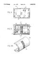
- FIG. 1 is a perspective view of the present invention showing the low and compact profile offered by the fixture.
- FIG. 2 is a front elevational view of the invention prominently showing the lens cover and the low frontal profile.
- FIG. 3 is an exploded perspective view of the component pieces which comprise the present invention.
- FIG. 4 is rear elevational view showing the mounting template and an external view of the wire slots.
- FIG. 5 is a front elevational view into the interior of the fixture with the lens removed, and shows a lamp drawn in phantom lines with portions of the step lock mechanism of the housing shown in the background.
- FIG. 5A is a rear perspective of the housing depicting spaced depressions formed along a vertical center line in its mid-section.
- FIG. 6 is a front elevational view into the interior of the fixture with the lens and housing removed.
- FIG. 7 is a side cut-away view taken from lines 7--7 in FIG. 5 and shows a sectional view of the step lock mechanism and portions of the lamp socket and boss.
- FIG. 8 is a side cut-away view taken from lines 8--8 in FIG. 6 and shows an end cap attached to the sectioned mounting bracket and in the detached position (drawn in phantom lines).
- FIG. 1 depicts the adjustable outdoor light designated with numeral 10.
- Outdoor light 10 is comprised of end caps 21 and 22, mounting bracket 30, housing 40 and cover lens 50.
- the phantom lines shown in FIG. 1 depict an external lead line.
- FIG. 2 shows the low frontal profile offered by the outdoor light fixture and the maximum coverage of the anterior area with cover lens 50.
- Cover lens 50 is a detachable, light-diffusing spread lens comprised of a plurality of parallel, elongated ridges as shown. The elongated ridges provide an even spread of illumination through a lateral and horizontal "prism effect.”
- FIG. 3 depicts the primary component pieces of the outdoor light in an exploded perspective view.
- Both end caps 21 and 22 have snap locks such as 25 and 25' which snap conveniently into mounting bracket 30 for easy assembly.
- the front portion of housing 40 is designed to receive lens 50, while the side aspects of housing 40 engage end caps 21 and 22.
- the mounting bracket 30 includes a locking knob 35 which adjustably engages the step lock mechanism 45 to adjustably lock housing 40.
- end cap 21 contains a socket mounting boss 23 to which is mounted lamp socket 24.
- FIG. 3 shows boss 23 as being located on end cap 21, one skilled in the art can appreciate that boss 23 could be located elsewhere within the housing 40, such as on the other end cap 22, without detracting from the present concept.
- substantially all components are made of weather resistant non-metallic material.
- mounting bracket 30 and lens 50 can be made of a polycarbonate called LexanTM
- housing 40 can be made of a plastic, polyphenylene sulfite (PPS) available under the trade name RytonTM.
- PPS polyphenylene sulfite
- Such materials are particularly suited for harsh environmental areas such as coastal regions where salt spray devastates conventional deck lights such as those made of oxidizable metals or degradable wood.
- FIG. 4 is the rear elevational view of mounting bracket 30 and shows mounting template 31 having wire slots 36 and 36'.
- FIG. 5 is a front elevational view into the interior of the fixture with the lens (50) removed, and shows a lamp drawn in phantom lines in the foreground with step lock mechanism 45 of housing 40 shown in the background.
- FIG. 5A is a rear perspective view showing step lock mechanism 45 as comprising spaced depressions formed in the convex outer surface of housing 40. In the preferred embodiment, the spaced depressions of step lock mechanism 45 are formed along a vertical center line in the mid-section of housing 40, as shown in FIGS. 5 and 5A.
- step lock mechanism 45 is depicted in FIG. 5A as comprising a series of spaced depressions formed into housing 40 during casting or extrusion, which cooperate with locking knob 35 (FIG.
- the step lock mechanism can comprise a series of depressions, protrusions or other physical forms of various shapes and sizes.
- the depressions, protrusions or other components of the step lock mechanism do not necessarily have to be vertically aligned along a single center line.
- the components could be spaced along different horizontal or vertical lines or set up in a type of "checkerboard" pattern, to name but a few examples.
- FIG. 6 is another front elevational view into the interior of outdoor light 10 with the lens (50) and housing (40) removed.
- the interior aspects of mounting bracket 30 such as wire slots 36 and 36' are shown in the background along with locking knob 35.
- Locking knob 35 and mounting bracket 30 are cast from the same mold, and FIG. 3 shows knob 35 extending from the lower aspects of a rectangular, cut-out portion in bracket 30.
- FIG. 7 is a side cut-away view taken from lines 7--7 in FIG. 5, and depicts a sectional view of step lock mechanism 45 which shows a series of spaced protrusions 46 and depressions 47 in an arcuate line formed in housing 40. Spaced depressions 47 formed in the exterior convex surface of housing 40 sequentially engage locking knob 35 of mounting bracket 30 to provide incremental stepwise locking of knob 35.
- step lock mechanism 45 in conjunction with locking knob 35, allows for incremental angular adjustment of housing 40 for variations in the angle and direction of illumination in the upward or downward direction.
- This feature allows the outdoor light to be installed in substantially any position on a deck, provide the desired angle and direction of illumination and maintain its low profile nature.
- FIG. 7 also depicts lamp socket 24 on boss 23 of end cap 21.
- FIG. 8 is a side cut-away view taken from lines 8--8 in FIG. 6 and shows end cap 22 attached to the sectioned mounting bracket 30 and in the detached position (drawn in phantom lines). Also depicted are snap locks 25' and 25" of end cap 22 positioned within mounting bracket 30.
- An exemplary installation procedure begins with removal of lens 50 with a small flat screw-driver by pressing either notch 51 or 51' (shown in FIG. 2). Referring to FIG. 3 for reference, housing 40 is rotated on bracket 30 so that the open side of housing 40 is pointed up towards bracket 30. Housing 40 is then removed from bracket 30 and if a lamp is supplied, it too is removed from socket 24.
- wire slots 36 and 36' are drilled through wire slots 36 and 36' into the mounting surface. Screws are positioned into the wire slots while also routing wire through at least one slot being careful to avoid pinching the wire. The screws are then drilled into the mounting surface.
- Housing 40 is replaced into bracket 30, followed by placement of a desired lamp (such as a low voltage wedge lamp) into socket 24.
- Lens 50 is next replaced, and wiring according to appropriate voltage is performed. Finally, the appropriate angle is adjusted using a flat screwdriver in the notches (such as 51) of lens 50 to direct illumination in the desired sector.
Abstract
Description
Claims (4)
Priority Applications (2)
| Application Number | Priority Date | Filing Date | Title |
|---|---|---|---|
| US08/527,406 US5642934A (en) | 1995-09-13 | 1995-09-13 | Adjustable outdoor light |
| CA002185401A CA2185401C (en) | 1995-09-13 | 1996-09-12 | Adjustable outdoor light |
Applications Claiming Priority (1)
| Application Number | Priority Date | Filing Date | Title |
|---|---|---|---|
| US08/527,406 US5642934A (en) | 1995-09-13 | 1995-09-13 | Adjustable outdoor light |
Publications (1)
| Publication Number | Publication Date |
|---|---|
| US5642934A true US5642934A (en) | 1997-07-01 |
Family
ID=24101336
Family Applications (1)
| Application Number | Title | Priority Date | Filing Date |
|---|---|---|---|
| US08/527,406 Expired - Lifetime US5642934A (en) | 1995-09-13 | 1995-09-13 | Adjustable outdoor light |
Country Status (2)
| Country | Link |
|---|---|
| US (1) | US5642934A (en) |
| CA (1) | CA2185401C (en) |
Cited By (40)
| Publication number | Priority date | Publication date | Assignee | Title |
|---|---|---|---|---|
| US6290376B1 (en) | 2000-04-05 | 2001-09-18 | Genlyte Thomas Group Llc | Adjustment mechanism for luminaire |
| EP1348904A1 (en) * | 2002-03-26 | 2003-10-01 | B/E Aerospace, Inc. | Illumination assembly with an adjustable direction mounting |
| EP1577612A2 (en) * | 2004-03-19 | 2005-09-21 | Beghelli S.p.A. | Support for emergency lighting devices |
| US20070147031A1 (en) * | 2004-06-10 | 2007-06-28 | Claude Barozzini | Garage Light Luminaire with Circular Compact Fluorescent Emergency Lighting Optics |
| US20070253192A1 (en) * | 2006-04-28 | 2007-11-01 | Genlyte Thomas Group Llc | Rear Trim Ring for a Vandal Resistant Luminaire |
| US7296914B1 (en) | 2004-03-03 | 2007-11-20 | Genlyte Thomas Group, Llc | Multiple position luminaire |
| US7325938B2 (en) | 2002-06-05 | 2008-02-05 | Genlyte Thomas Group, Llc | Indirector light fixture |
| US20080137351A1 (en) * | 2006-06-19 | 2008-06-12 | Genlyte Thomas Group, Llc | Traditional Style Post-Top Luminaire with Relamping Module and Method |
| US20080186729A1 (en) * | 2007-02-01 | 2008-08-07 | Kenneth Edward Madden | Vehicle headlight mounting assembly |
| US20080205069A1 (en) * | 2007-02-27 | 2008-08-28 | Lumec, Inc. | Sealed Acorn Luminaire |
| US7422350B2 (en) | 2006-06-19 | 2008-09-09 | Genlyte Thomas Group, Llc | Pendent style luminaire split design |
| US20080219008A1 (en) * | 2007-03-06 | 2008-09-11 | Canlyte Inc. | Lighting Device with Composite Reflector |
| US20080232111A1 (en) * | 2007-02-28 | 2008-09-25 | Canlyte Inc. | Low Up-Light Cutoff Acorn Style Luminaire |
| USD609381S1 (en) | 2008-04-21 | 2010-02-02 | Lumec, Inc. | Luminaire |
| USD609382S1 (en) | 2008-04-21 | 2010-02-02 | Lumec Inc. | Luminaire |
| USD609838S1 (en) | 2008-12-01 | 2010-02-09 | Koninklijke Philips Electronics N.V. | Luminaire |
| USD610288S1 (en) | 2008-12-01 | 2010-02-16 | Koninklijke Philips Electronics N.V. | Luminaire |
| US7661837B1 (en) | 2008-03-17 | 2010-02-16 | The Crane Group Companies Limited | Deck lighting system |
| USD610295S1 (en) | 2008-12-01 | 2010-02-16 | Koninklijke Philips Electronics N.V. | Luminaire |
| USD610296S1 (en) | 2009-01-12 | 2010-02-16 | Koninklijke Philips Electronics N.V. | Sconce light fixture |
| US7686485B1 (en) | 2008-03-17 | 2010-03-30 | The Crane Group Companies Limited | Outdoor deck lighting system |
| US7695169B2 (en) | 2006-04-28 | 2010-04-13 | Genlyte Thomas Group Llc | Gasket system for a vandal resistant luminaire |
| USD619293S1 (en) | 2008-12-01 | 2010-07-06 | Koninklijke Philips Electronics N.V. | Luminaire |
| US7841755B1 (en) | 2008-05-05 | 2010-11-30 | Genlyte Thomas Group Llc | Luminaire and mounting bracket combination |
| US7862196B1 (en) | 2008-03-17 | 2011-01-04 | The Crane Group Companies Limited | Baluster light system |
| US7934848B1 (en) | 2008-03-17 | 2011-05-03 | The Crane Group Companies Limited | Stair riser light and method for installing same |
| US8061666B1 (en) | 2008-08-05 | 2011-11-22 | Philips Electronics Ltd | Adapter assembly for pole luminaire |
| USD652557S1 (en) | 2010-08-18 | 2012-01-17 | Koninklijke Philiips Electronics N.V. | Luminaire for road lighting |
| USD652978S1 (en) | 2010-08-18 | 2012-01-24 | Koninklijke Philips Electronics N.V. | Luminaire for road lighting |
| DE202010013177U1 (en) * | 2010-12-21 | 2012-03-26 | Zumtobel Lighting Gmbh | Holding device for a light |
| US20130258680A1 (en) * | 2012-04-03 | 2013-10-03 | Tsui-Yun WONG | Light casing |
| GB2524108A (en) * | 2014-03-14 | 2015-09-16 | Saf T Glo Ltd | Lighting systems |
| US9188320B2 (en) | 2006-10-09 | 2015-11-17 | Genlyte Thomas Group, Llc | Luminaire junction box |
| USD757983S1 (en) | 2015-02-20 | 2016-05-31 | Volt, LLC | Deck light |
| USD757982S1 (en) | 2015-02-20 | 2016-05-31 | Volt, LLC | Deck light |
| USD757984S1 (en) | 2015-02-20 | 2016-05-31 | Volt, LLC | Deck light |
| US20160245468A1 (en) * | 2015-02-20 | 2016-08-25 | Volt, LLC | Deck light with interchangeable housings |
| US20160363297A1 (en) * | 2014-12-03 | 2016-12-15 | CP IP Holdings Limited | Lighting arrangement |
| US10234109B1 (en) * | 2016-07-27 | 2019-03-19 | Cooper Technologies Company | Single-piece end cap |
| US10279910B2 (en) | 2014-03-14 | 2019-05-07 | Saf-T-Glo Limited | Lighting systems |
Citations (6)
| Publication number | Priority date | Publication date | Assignee | Title |
|---|---|---|---|---|
| US4447863A (en) * | 1983-01-24 | 1984-05-08 | Pittway Corp | Hand-held light with swivel head |
| US4602320A (en) * | 1985-02-21 | 1986-07-22 | Redondo Investment Limited | Adjustable safety lamp for vehicle windows |
| US4816969A (en) * | 1988-02-05 | 1989-03-28 | Hospital Systems Inc. | Wall-mounted over-bed lighting fixture |
| US5278737A (en) * | 1991-11-06 | 1994-01-11 | Visa Lighting Corporation | Wall and ceiling lighting unit |
| US5377087A (en) * | 1992-01-15 | 1994-12-27 | Gulton Industries, Inc. | Passenger reading light |
| US5404297A (en) * | 1994-01-21 | 1995-04-04 | Puritan-Bennett Corporation | Aircraft reading light |
-
1995
- 1995-09-13 US US08/527,406 patent/US5642934A/en not_active Expired - Lifetime
-
1996
- 1996-09-12 CA CA002185401A patent/CA2185401C/en not_active Expired - Lifetime
Patent Citations (6)
| Publication number | Priority date | Publication date | Assignee | Title |
|---|---|---|---|---|
| US4447863A (en) * | 1983-01-24 | 1984-05-08 | Pittway Corp | Hand-held light with swivel head |
| US4602320A (en) * | 1985-02-21 | 1986-07-22 | Redondo Investment Limited | Adjustable safety lamp for vehicle windows |
| US4816969A (en) * | 1988-02-05 | 1989-03-28 | Hospital Systems Inc. | Wall-mounted over-bed lighting fixture |
| US5278737A (en) * | 1991-11-06 | 1994-01-11 | Visa Lighting Corporation | Wall and ceiling lighting unit |
| US5377087A (en) * | 1992-01-15 | 1994-12-27 | Gulton Industries, Inc. | Passenger reading light |
| US5404297A (en) * | 1994-01-21 | 1995-04-04 | Puritan-Bennett Corporation | Aircraft reading light |
Cited By (54)
| Publication number | Priority date | Publication date | Assignee | Title |
|---|---|---|---|---|
| US6607292B2 (en) | 2000-04-05 | 2003-08-19 | Genlyte Thomas Group Llc | Adjustment mechanism for luminaire |
| US6290376B1 (en) | 2000-04-05 | 2001-09-18 | Genlyte Thomas Group Llc | Adjustment mechanism for luminaire |
| EP1348904A1 (en) * | 2002-03-26 | 2003-10-01 | B/E Aerospace, Inc. | Illumination assembly with an adjustable direction mounting |
| US6726348B2 (en) | 2002-03-26 | 2004-04-27 | B/E Aerospace, Inc. | Illumination assembly and adjustable direction mounting |
| US7325938B2 (en) | 2002-06-05 | 2008-02-05 | Genlyte Thomas Group, Llc | Indirector light fixture |
| US7575336B2 (en) | 2002-06-05 | 2009-08-18 | Genlyte Thomas Group Llc | Indirector light fixture |
| US20080101075A1 (en) * | 2002-06-05 | 2008-05-01 | Genlyte Thomas Group, Llc | Indirector Light Fixture |
| US7455428B1 (en) | 2004-03-03 | 2008-11-25 | Genlyte Thomas Group Llc | Gasket for multiple position luminaire |
| US7296914B1 (en) | 2004-03-03 | 2007-11-20 | Genlyte Thomas Group, Llc | Multiple position luminaire |
| EP1577612A2 (en) * | 2004-03-19 | 2005-09-21 | Beghelli S.p.A. | Support for emergency lighting devices |
| EP1577612A3 (en) * | 2004-03-19 | 2007-04-04 | Beghelli S.p.A. | Support for emergency lighting devices |
| US7374310B2 (en) | 2004-06-10 | 2008-05-20 | Genlyte Thomas Group, Llc | Garage light luminaire with circular compact fluorescent emergency lighting optics |
| US20070147031A1 (en) * | 2004-06-10 | 2007-06-28 | Claude Barozzini | Garage Light Luminaire with Circular Compact Fluorescent Emergency Lighting Optics |
| US20070253192A1 (en) * | 2006-04-28 | 2007-11-01 | Genlyte Thomas Group Llc | Rear Trim Ring for a Vandal Resistant Luminaire |
| US7695169B2 (en) | 2006-04-28 | 2010-04-13 | Genlyte Thomas Group Llc | Gasket system for a vandal resistant luminaire |
| US7654707B2 (en) | 2006-04-28 | 2010-02-02 | Qualcomm Incorporated | Rear trim ring for a vandal resistant luminaire |
| US20080137351A1 (en) * | 2006-06-19 | 2008-06-12 | Genlyte Thomas Group, Llc | Traditional Style Post-Top Luminaire with Relamping Module and Method |
| US7422350B2 (en) | 2006-06-19 | 2008-09-09 | Genlyte Thomas Group, Llc | Pendent style luminaire split design |
| US9188320B2 (en) | 2006-10-09 | 2015-11-17 | Genlyte Thomas Group, Llc | Luminaire junction box |
| US20080186729A1 (en) * | 2007-02-01 | 2008-08-07 | Kenneth Edward Madden | Vehicle headlight mounting assembly |
| US20080205069A1 (en) * | 2007-02-27 | 2008-08-28 | Lumec, Inc. | Sealed Acorn Luminaire |
| US7611265B2 (en) | 2007-02-27 | 2009-11-03 | Lumec, Inc. | Sealed acorn luminaire having a one-way outflow seal and a one-way inflow electrical grommet seal |
| US7946734B2 (en) | 2007-02-28 | 2011-05-24 | Philips Electronics Ltd | Low up-light cutoff acorn style luminaire |
| US20080232111A1 (en) * | 2007-02-28 | 2008-09-25 | Canlyte Inc. | Low Up-Light Cutoff Acorn Style Luminaire |
| US20080219008A1 (en) * | 2007-03-06 | 2008-09-11 | Canlyte Inc. | Lighting Device with Composite Reflector |
| US7712929B2 (en) | 2007-03-06 | 2010-05-11 | Canlyte Inc. | Lighting device with composite reflector |
| US7862196B1 (en) | 2008-03-17 | 2011-01-04 | The Crane Group Companies Limited | Baluster light system |
| US7661837B1 (en) | 2008-03-17 | 2010-02-16 | The Crane Group Companies Limited | Deck lighting system |
| US7686485B1 (en) | 2008-03-17 | 2010-03-30 | The Crane Group Companies Limited | Outdoor deck lighting system |
| US7934848B1 (en) | 2008-03-17 | 2011-05-03 | The Crane Group Companies Limited | Stair riser light and method for installing same |
| USD609382S1 (en) | 2008-04-21 | 2010-02-02 | Lumec Inc. | Luminaire |
| USD609381S1 (en) | 2008-04-21 | 2010-02-02 | Lumec, Inc. | Luminaire |
| US7841755B1 (en) | 2008-05-05 | 2010-11-30 | Genlyte Thomas Group Llc | Luminaire and mounting bracket combination |
| US8061666B1 (en) | 2008-08-05 | 2011-11-22 | Philips Electronics Ltd | Adapter assembly for pole luminaire |
| USD610288S1 (en) | 2008-12-01 | 2010-02-16 | Koninklijke Philips Electronics N.V. | Luminaire |
| USD609838S1 (en) | 2008-12-01 | 2010-02-09 | Koninklijke Philips Electronics N.V. | Luminaire |
| USD610295S1 (en) | 2008-12-01 | 2010-02-16 | Koninklijke Philips Electronics N.V. | Luminaire |
| USD619293S1 (en) | 2008-12-01 | 2010-07-06 | Koninklijke Philips Electronics N.V. | Luminaire |
| USD610296S1 (en) | 2009-01-12 | 2010-02-16 | Koninklijke Philips Electronics N.V. | Sconce light fixture |
| USD652557S1 (en) | 2010-08-18 | 2012-01-17 | Koninklijke Philiips Electronics N.V. | Luminaire for road lighting |
| USD652978S1 (en) | 2010-08-18 | 2012-01-24 | Koninklijke Philips Electronics N.V. | Luminaire for road lighting |
| DE202010013177U1 (en) * | 2010-12-21 | 2012-03-26 | Zumtobel Lighting Gmbh | Holding device for a light |
| US20130258680A1 (en) * | 2012-04-03 | 2013-10-03 | Tsui-Yun WONG | Light casing |
| US8974093B2 (en) * | 2012-04-03 | 2015-03-10 | Tsui-Yun WONG | Light casing with movable part |
| GB2524108A (en) * | 2014-03-14 | 2015-09-16 | Saf T Glo Ltd | Lighting systems |
| US10279910B2 (en) | 2014-03-14 | 2019-05-07 | Saf-T-Glo Limited | Lighting systems |
| GB2524108B (en) * | 2014-03-14 | 2020-09-16 | Saf-T-Glo Ltd | Lighting systems |
| US20160363297A1 (en) * | 2014-12-03 | 2016-12-15 | CP IP Holdings Limited | Lighting arrangement |
| US10119685B2 (en) * | 2014-12-03 | 2018-11-06 | CP IP Holdings Limited | Lighting arrangement |
| USD757983S1 (en) | 2015-02-20 | 2016-05-31 | Volt, LLC | Deck light |
| USD757982S1 (en) | 2015-02-20 | 2016-05-31 | Volt, LLC | Deck light |
| USD757984S1 (en) | 2015-02-20 | 2016-05-31 | Volt, LLC | Deck light |
| US20160245468A1 (en) * | 2015-02-20 | 2016-08-25 | Volt, LLC | Deck light with interchangeable housings |
| US10234109B1 (en) * | 2016-07-27 | 2019-03-19 | Cooper Technologies Company | Single-piece end cap |
Also Published As
| Publication number | Publication date |
|---|---|
| CA2185401A1 (en) | 1997-03-14 |
| CA2185401C (en) | 2007-06-12 |
Similar Documents
| Publication | Publication Date | Title |
|---|---|---|
| US5642934A (en) | Adjustable outdoor light | |
| US5452193A (en) | Inclined ceiling downlight fixtures | |
| US4410933A (en) | Luminaire trunnion degree marker and reset stop | |
| US6585398B1 (en) | Post top deck light fixture | |
| US5788363A (en) | Lamp unit attaching structure | |
| WO2006060905A1 (en) | Assembly of light emitting diodes for lighting applications | |
| US4426676A (en) | Luminaire mounting | |
| EP1470999A2 (en) | Lantern, preferably for use on board of ships, in particular on sports ships | |
| CA2645968C (en) | Adjustable reflector luminaire | |
| JP3509096B2 (en) | lighting equipment | |
| DE19922142A1 (en) | Headlamp assembly for use with a motor vehicle | |
| US5386354A (en) | Adjustable beam security light | |
| US6604842B2 (en) | Picture light | |
| CA2166641A1 (en) | Light Stake | |
| EP2020561A1 (en) | Luminaire | |
| MXPA97005036A (en) | Adjustable light for exter | |
| JP2005066122A (en) | Structure of storage body with lighting | |
| KR200395652Y1 (en) | structure of illumination lamp | |
| US4414618A (en) | Lamp shade adjuster and holder | |
| JPH0332005Y2 (en) | ||
| DE4410898C2 (en) | lamp | |
| JPH0727724B2 (en) | Baffle light fixture | |
| CN207907067U (en) | A kind of Projecting Lamp with Phototube Coupling light adjusting circuit | |
| US6454424B1 (en) | RV light lens | |
| JPH0728646Y2 (en) | Rainproof lighting |
Legal Events
| Date | Code | Title | Description |
|---|---|---|---|
| AS | Assignment |
Owner name: HADCO DIVISION OF THE GENLYTE GROUP INCORPORATED, Free format text: ASSIGNMENT OF ASSIGNORS INTEREST;ASSIGNOR:HADDAD, ERIC;REEL/FRAME:007670/0331 Effective date: 19950911 |
|
| STCF | Information on status: patent grant |
Free format text: PATENTED CASE |
|
| FPAY | Fee payment |
Year of fee payment: 4 |
|
| AS | Assignment |
Owner name: GENLYTE THOMAS GROUP LLC, A DELAWARE LIMITED LIABI Free format text: MEMORANDUM OF ASSIGNMENT EFFECTIVE 08/30/1998;ASSIGNOR:HADCO DIVISION OF THE GENLYTE GROUP INCORPORATED, AN ASSUMED NAME OF THE GENLYTE GROUP INCORPORATED;REEL/FRAME:011442/0441 Effective date: 20001222 |
|
| FPAY | Fee payment |
Year of fee payment: 8 |
|
| FPAY | Fee payment |
Year of fee payment: 12 |