US5646996A - Automatic resynchronization of transmitter in the event of corrupted memory - Google Patents
Automatic resynchronization of transmitter in the event of corrupted memory Download PDFInfo
- Publication number
- US5646996A US5646996A US08/523,846 US52384695A US5646996A US 5646996 A US5646996 A US 5646996A US 52384695 A US52384695 A US 52384695A US 5646996 A US5646996 A US 5646996A
- Authority
- US
- United States
- Prior art keywords
- transmitter
- receiver
- random number
- error check
- resynchronization
- Prior art date
- Legal status (The legal status is an assumption and is not a legal conclusion. Google has not performed a legal analysis and makes no representation as to the accuracy of the status listed.)
- Expired - Fee Related
Links
Images


Classifications
-
- G—PHYSICS
- G07—CHECKING-DEVICES
- G07C—TIME OR ATTENDANCE REGISTERS; REGISTERING OR INDICATING THE WORKING OF MACHINES; GENERATING RANDOM NUMBERS; VOTING OR LOTTERY APPARATUS; ARRANGEMENTS, SYSTEMS OR APPARATUS FOR CHECKING NOT PROVIDED FOR ELSEWHERE
- G07C9/00—Individual registration on entry or exit
- G07C9/00174—Electronically operated locks; Circuits therefor; Nonmechanical keys therefor, e.g. passive or active electrical keys or other data carriers without mechanical keys
- G07C9/00182—Electronically operated locks; Circuits therefor; Nonmechanical keys therefor, e.g. passive or active electrical keys or other data carriers without mechanical keys operated with unidirectional data transmission between data carrier and locks
-
- H—ELECTRICITY
- H04—ELECTRIC COMMUNICATION TECHNIQUE
- H04L—TRANSMISSION OF DIGITAL INFORMATION, e.g. TELEGRAPHIC COMMUNICATION
- H04L9/00—Cryptographic mechanisms or cryptographic arrangements for secret or secure communications; Network security protocols
- H04L9/12—Transmitting and receiving encryption devices synchronised or initially set up in a particular manner
-
- H—ELECTRICITY
- H04—ELECTRIC COMMUNICATION TECHNIQUE
- H04L—TRANSMISSION OF DIGITAL INFORMATION, e.g. TELEGRAPHIC COMMUNICATION
- H04L9/00—Cryptographic mechanisms or cryptographic arrangements for secret or secure communications; Network security protocols
- H04L9/32—Cryptographic mechanisms or cryptographic arrangements for secret or secure communications; Network security protocols including means for verifying the identity or authority of a user of the system or for message authentication, e.g. authorization, entity authentication, data integrity or data verification, non-repudiation, key authentication or verification of credentials
- H04L9/3226—Cryptographic mechanisms or cryptographic arrangements for secret or secure communications; Network security protocols including means for verifying the identity or authority of a user of the system or for message authentication, e.g. authorization, entity authentication, data integrity or data verification, non-repudiation, key authentication or verification of credentials using a predetermined code, e.g. password, passphrase or PIN
-
- H—ELECTRICITY
- H04—ELECTRIC COMMUNICATION TECHNIQUE
- H04L—TRANSMISSION OF DIGITAL INFORMATION, e.g. TELEGRAPHIC COMMUNICATION
- H04L9/00—Cryptographic mechanisms or cryptographic arrangements for secret or secure communications; Network security protocols
- H04L9/32—Cryptographic mechanisms or cryptographic arrangements for secret or secure communications; Network security protocols including means for verifying the identity or authority of a user of the system or for message authentication, e.g. authorization, entity authentication, data integrity or data verification, non-repudiation, key authentication or verification of credentials
- H04L9/3236—Cryptographic mechanisms or cryptographic arrangements for secret or secure communications; Network security protocols including means for verifying the identity or authority of a user of the system or for message authentication, e.g. authorization, entity authentication, data integrity or data verification, non-repudiation, key authentication or verification of credentials using cryptographic hash functions
- H04L9/3242—Cryptographic mechanisms or cryptographic arrangements for secret or secure communications; Network security protocols including means for verifying the identity or authority of a user of the system or for message authentication, e.g. authorization, entity authentication, data integrity or data verification, non-repudiation, key authentication or verification of credentials using cryptographic hash functions involving keyed hash functions, e.g. message authentication codes [MACs], CBC-MAC or HMAC
-
- G—PHYSICS
- G07—CHECKING-DEVICES
- G07C—TIME OR ATTENDANCE REGISTERS; REGISTERING OR INDICATING THE WORKING OF MACHINES; GENERATING RANDOM NUMBERS; VOTING OR LOTTERY APPARATUS; ARRANGEMENTS, SYSTEMS OR APPARATUS FOR CHECKING NOT PROVIDED FOR ELSEWHERE
- G07C9/00—Individual registration on entry or exit
- G07C9/00174—Electronically operated locks; Circuits therefor; Nonmechanical keys therefor, e.g. passive or active electrical keys or other data carriers without mechanical keys
- G07C9/00182—Electronically operated locks; Circuits therefor; Nonmechanical keys therefor, e.g. passive or active electrical keys or other data carriers without mechanical keys operated with unidirectional data transmission between data carrier and locks
- G07C2009/00238—Electronically operated locks; Circuits therefor; Nonmechanical keys therefor, e.g. passive or active electrical keys or other data carriers without mechanical keys operated with unidirectional data transmission between data carrier and locks the transmittted data signal containing a code which is changed
- G07C2009/00253—Electronically operated locks; Circuits therefor; Nonmechanical keys therefor, e.g. passive or active electrical keys or other data carriers without mechanical keys operated with unidirectional data transmission between data carrier and locks the transmittted data signal containing a code which is changed dynamically, e.g. variable code - rolling code
-
- G—PHYSICS
- G07—CHECKING-DEVICES
- G07C—TIME OR ATTENDANCE REGISTERS; REGISTERING OR INDICATING THE WORKING OF MACHINES; GENERATING RANDOM NUMBERS; VOTING OR LOTTERY APPARATUS; ARRANGEMENTS, SYSTEMS OR APPARATUS FOR CHECKING NOT PROVIDED FOR ELSEWHERE
- G07C9/00—Individual registration on entry or exit
- G07C9/00174—Electronically operated locks; Circuits therefor; Nonmechanical keys therefor, e.g. passive or active electrical keys or other data carriers without mechanical keys
- G07C2009/00753—Electronically operated locks; Circuits therefor; Nonmechanical keys therefor, e.g. passive or active electrical keys or other data carriers without mechanical keys operated by active electrical keys
- G07C2009/00769—Electronically operated locks; Circuits therefor; Nonmechanical keys therefor, e.g. passive or active electrical keys or other data carriers without mechanical keys operated by active electrical keys with data transmission performed by wireless means
-
- G—PHYSICS
- G07—CHECKING-DEVICES
- G07C—TIME OR ATTENDANCE REGISTERS; REGISTERING OR INDICATING THE WORKING OF MACHINES; GENERATING RANDOM NUMBERS; VOTING OR LOTTERY APPARATUS; ARRANGEMENTS, SYSTEMS OR APPARATUS FOR CHECKING NOT PROVIDED FOR ELSEWHERE
- G07C2209/00—Indexing scheme relating to groups G07C9/00 - G07C9/38
- G07C2209/06—Involving synchronization or resynchronization between transmitter and receiver; reordering of codes
Definitions
- the present invention relates generally to keyless entry systems. More particularly, the invention relates to a method for automatically resynchronizing the transmitter/receiver pair when synchronization is lost due to momentary power failure or a low battery condition, for example.
- Rolling code authentication is a common form of vehicle entry security.
- a transmitter is provided in the form of a key fob and a receiver is positioned in the vehicle where it is able to receive encoded transmission from the key fob transmitter.
- Rolling code authentication can be performed by employing a simple linear counter which advances with each key fob command.
- the receiver in the vehicle is configured to always expect an increasing value and therefore it disallows repeating counter values.
- More complex authentication using linear shift feedback register (LFSR) technology is also used as a more secure technique for vehicle entry security.
- LFSR linear shift feedback register
- a rolling code authentication system can occasionally fall out of synchronization when the counter values of the transmitter are less than that of the receiver or when the transmitter counter values are greater than those of the receiver by a predetermined number.
- One reason for losing synchronization is corrupted volatile memory, which can be due to momentary loss of battery power or low battery voltage.
- One way to ensure against loss of synchronization is to outfit the transmitter with a nonvolatile memory such as an EEPROM which can be used to store the rolling values so they will not be lost. Being nonvolatile, the EEPROM will not lose synchronization due to a power interruption (e.g. loose battery connection or battery failure). The EEPROM protects the integrity of the counters when the internal RAM is powered-off.
- a nonvolatile memory such as an EEPROM which can be used to store the rolling values so they will not be lost.
- the EEPROM will not lose synchronization due to a power interruption (e.g. loose battery connection or battery failure).
- the EEPROM protects the integrity of the counters when the internal RAM is powered-off.
- EEPROM devices are comparatively expensive and it would be desirable to eliminate them from the rolling code authentication circuitry. This presents a problem, since without nonvolatile memory, a system would have to rely on RAM (volatile memory) to store counter values. The need to rely on RAM increases the possibility of corrupted counter values, since even temporary loss of power through a loose battery connection or loss of battery charge would break synchronization.
- RAM volatile memory
- the present invention addresses the synchronization problem by providing a system which automatically resynchronizes the transmitter/receiver pair when corrupted memory is detected. Ordinarily the user is not even aware resynchronization is being performed. This is accomplished by calculating and storing a first checksum indicative of the state of the transmitter at a first instance in time. Thereafter, the communications sequence is initiated between transmitter and receiver and the initiation of this sequence automatically causes a second checksum to be calculated. The second checksum is indicative of the state of the transmitter at that second instance in time. The checksums are compared and if the checksums are different, the resynchronization sequence is automatically initiated.
- FIG. 1 is a block diagram of an exemplary four bit linear feedback shift register, useful in understanding the principles of the invention
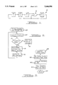
- FIG. 2 is an overview flowchart diagram illustrating the principles of the invention
- FIGS. 3-6 are flowchart diagrams setting forth the synchronization method of the invention in detail.
- FIG. 1 a four bit linear feedback shift register (LFSR) is depicted at 10.
- the shift register includes four memory cells in which four bits are stored, designated bit 3, bit 2 . . . bit 0, consecutively.
- the shift register is configured so that each cycle or rotation causes the contents of one bit to be shifted or transferred to its rightmost neighbor (with the exception of bits which feed an exclusive OR device).
- the LFSR device also includes one or more exclusive OR operations.
- FIG. 1 a single exclusive OR 12 has been illustrated, with its output supplying bit 0 and with its inputs connected to the output of bit 1 and the output of bit 0, as illustrated.
- the contents of bit 1 are combined with the contents of bit 0 in an exclusive OR operation and the resultant is then stored at bit 0.
- the linear feedback shift register 10 illustrated in FIG. 1 is merely provided as an example. In practice, the shift register can be any number of bits, typically a larger number than four bits, and the number and location of exclusive OR operations can vary to provide different encryption codes.
- the linear feedback shift register works by rotating the authentication bits, n times, through the shift register with exclusive OR feedback taps between a few of the bit locations.
- the transmitter performs a linear feedback shift register (LFSR) shift operation, which scrambles the authentication information and sends this scrambled authentication information to the receiver along with the selected command (unlock, lock, trunk, etc.).
- LFSR linear feedback shift register
- An identical LFSR operation on the receiver authentication variables is performed in the receiver after it receives a command from the transmitter.
- the receiver compares the results of its own LFSR operation to the authentication variables sent by the transmitter.
- the authentication information is validated if the receiver comparison matches.
- a synchronization issue can arise when the transmitter authentication variables are lost due to power interruption.
- the present invention provides a method for automatically detecting corrupted authentication variables and providing for a resynchronization of those variables.
- the synchronizing method is automatically invoked when the transmit sequence is initiated through a user-pressed key. This is illustrated at step 20.
- a checksum is calculated at step 22 and this checksum is compared with a stored checksum calculated during the previous transmission sequence. If the checksums match, the user-selected command is sent as indicated at step 30. On the other hand, if the checksums do not match a resync command and a series of resync variables are sent at step 26. Thereafter, a new checksum is calculated at step 28 and the routine then branches back to repeat steps 22 and 24.
- step 26 the receiver is supplied with resynchronization variables to allow it to also match the new authentication code.
- step 102 the checksum previously stored is compared with the newly calculated checksum. If the checksums match the memory is declared not corrupted. On the other hand, if the checksums do not match the memory is declared corrupted. Thus, in step 104, if the memory is not corrupted, control proceeds to step 106. Step 106 ultimately leads to step 122 at which the user-selected command is executed. On the other hand, if the memory is corrupted control proceeds to step 126 whereby synchronization is re-established. The following will explain both possibilities.
- the user's keypad input is debounced and decoded by the transmitter microprocessor. This is illustrated at step 106. Thereafter, the transmitter rolling code or cryptographic algorithm is sequenced, as indicated at step 108. Additional details regarding the sequencing operations are set forth in connection with FIGS. 4 and 5.
- the transmitter assembles a message at step 110 and this message is broadcast at step 112 via RF or IR transmission to the receiver located in the vehicle.
- the vehicle receiver receives the transmitted message at step 114 whereupon the receiver performs its rolling code or cryptographic algorithm sequencing at step 116.
- the authentication codes generated at steps 108 and 116, respectively are compared at step 118. If the authentication codes match and if the transmitted command properly decodes, then the transmitter is deemed to be authentic at step 120 and the process command is performed at step 122.
- step 120 will cause the process to branch to step 124 at which the sequence is deemed to be out of synchronization or alternatively an invalid key fob transmitter may be assumed.
- step 124 either the wrong transmitter was used (in which case the command will never be successful) or the right transmitter was used but it is out of sequence with the receiver
- step 126 the transmitter initializes its counter and loads its LFSR variables with random numbers.
- the transmitter then assembles a message at step 128 and this message is transmitted via RF or IR transmission at step 130 to the receiver.
- step 132 a checksum of the transmitter RAM is calculated and stored.
- step 134 a comparison is made to determine whether any of the last five random numbers stored in the receiver match those broadcast by the transmitter. (Although the preferred embodiment tests five numbers, a larger or smaller set of numbers could be used, if desired.) If the numbers match, step 134 is declared to have failed and the LFSR variables sent by the transmitter are rejected by the receiver.
- the receiver and transmitter will stay out of synchronization.
- successful resynchronization is declared.
- the receiver acquires the resynchronization numbers sent from the transmitter and places them in its own rolling code LFSR variable registers, whereupon the transmitter and receiver will now both contain the same LFSR and counter variables and are therefore in synchronization.
- step 140 The LFSR sequence utilized by both transmitter and receiver is illustrated in FIG. 4. Beginning at step 140, the sequence proceeds to step 142 where the number of bytes in the sequence is supplied and a software loop is initiated to effect the LFSR rotation.
- one or more exclusive OR operations may be interposed between selected bits of a given byte or word. (In FIG. 1 a single exclusive OR operation was positioned between bit 1 and bit 0).
- step 142 the selected position of one or more exclusive OR operations is set up, so that the appropriate exclusive OR operations will occur as the cycle proceeds.
- the selected configuration of exclusive OR operations can be supplied as a digital word or "mask" to be applied as a setup parameter. Alternatively the mask can be permanently or semi-permanently manufactured into the system or programmed into the system by the manufacturer or dealer.
- step 144 a byte is fetched into the LFSR RAM variable so that the LFSR sequence can be performed upon it.
- steps 146, 148 and 150 a rotate-right operation is performed on the LFSR variable, with the most significant bit (MSB) having a forced zero in its carry register.
- MSB most significant bit
- the exclusive OR operations are performed at step 148, with the resultant being supplied as feedback terms in accordance with the setup mask established at step 142.
- step 150 the rotated byte resulting from steps 146 and 148 is stored into a temporary memory location.
- step 152 if there are additional bytes queued up for rotation, the sequence returns to step 144 where the next byte is fetched and the process is repeated.
- step 150 the temporary memory (stored as step 150) is written to the LFSR variable in RAM and control returns (step 156) to the calling program.
- FIG. 5 depicts, beginning at step 158, the manner of sequencing rolling codes.
- the rolling counter variable is retrieved from RAM, this variable is then incremented by one (step 162) and stored back in RAM (step 164). Control then returns to the calling program (step 166).
- the presently preferred embodiment assembles transmitter messages as illustrated in FIG. 6.
- the transmitter message is assembled by first placing the transmitter ID in the first transmission byte (step 170).
- a decision is made (step 172) as to whether the message is a resychronization message or a regular command.
- Regular commands are assembled (step 174) by placing the rolling bits and LFSR data in the next 39 bits to be transmitted. If the command is a resynchronization command, the message is assembled by first generating or fetching random numbers (step 176) which serve as LFSR/rolling number initial variables.
- the exclusive OR resync command is inserted into the message.
- the resynchronization bits are placed in the message along with the desired command into the next 39 transmission bits.
- the method of synchronizing transmitter and receiver is not limited to LFSR techniques.
- the invention can be used with any cryptographic authentication which is capable of supporting the checksum technique.
Abstract
Loss of synchronization between transmitter and receiver of a remote entry system is detected during the communication sequence between transmitter and receiver, by generating a checksum of the authentication code at the initiation of the communication sequence and comparing it with a checksum previously stored. If the checksums do not match an automatic resynchronization sequence is begun in which random numbers are generated by the transmitter and broadcast to the receiver for subsequent use as rolling code or linear feedback shift register variables.
Description
This is a continuation of U.S. patent application Ser. No. 08/148,668, filed on Nov. 5, 1993, now abandoned.
The present invention relates generally to keyless entry systems. More particularly, the invention relates to a method for automatically resynchronizing the transmitter/receiver pair when synchronization is lost due to momentary power failure or a low battery condition, for example.
Rolling code authentication is a common form of vehicle entry security. In such a system, a transmitter is provided in the form of a key fob and a receiver is positioned in the vehicle where it is able to receive encoded transmission from the key fob transmitter. Rolling code authentication can be performed by employing a simple linear counter which advances with each key fob command. The receiver in the vehicle is configured to always expect an increasing value and therefore it disallows repeating counter values. Thus to be in sync the transmitter counter should never fall behind the count of the receiver, nor should the transmitter counter be permitted to get too far ahead of the receiver count. More complex authentication using linear shift feedback register (LFSR) technology is also used as a more secure technique for vehicle entry security.
For a number of reasons, a rolling code authentication system can occasionally fall out of synchronization when the counter values of the transmitter are less than that of the receiver or when the transmitter counter values are greater than those of the receiver by a predetermined number. One reason for losing synchronization is corrupted volatile memory, which can be due to momentary loss of battery power or low battery voltage.
One way to ensure against loss of synchronization is to outfit the transmitter with a nonvolatile memory such as an EEPROM which can be used to store the rolling values so they will not be lost. Being nonvolatile, the EEPROM will not lose synchronization due to a power interruption (e.g. loose battery connection or battery failure). The EEPROM protects the integrity of the counters when the internal RAM is powered-off.
However, EEPROM devices are comparatively expensive and it would be desirable to eliminate them from the rolling code authentication circuitry. This presents a problem, since without nonvolatile memory, a system would have to rely on RAM (volatile memory) to store counter values. The need to rely on RAM increases the possibility of corrupted counter values, since even temporary loss of power through a loose battery connection or loss of battery charge would break synchronization.
The present invention addresses the synchronization problem by providing a system which automatically resynchronizes the transmitter/receiver pair when corrupted memory is detected. Ordinarily the user is not even aware resynchronization is being performed. This is accomplished by calculating and storing a first checksum indicative of the state of the transmitter at a first instance in time. Thereafter, the communications sequence is initiated between transmitter and receiver and the initiation of this sequence automatically causes a second checksum to be calculated. The second checksum is indicative of the state of the transmitter at that second instance in time. The checksums are compared and if the checksums are different, the resynchronization sequence is automatically initiated.
For a more complete understanding of the invention, its objects and advantages, reference may be made to the following specification and to the accompanying drawings.
FIG. 1 is a block diagram of an exemplary four bit linear feedback shift register, useful in understanding the principles of the invention;
FIG. 2 is an overview flowchart diagram illustrating the principles of the invention;
FIGS. 3-6 are flowchart diagrams setting forth the synchronization method of the invention in detail.
In order to understand the method of synchronizing some understanding of linear feedback shift register technology may be helpful, since the invention can be used with LFSR security systems. Accordingly, in FIG. 1 a four bit linear feedback shift register (LFSR) is depicted at 10. The shift register includes four memory cells in which four bits are stored, designated bit 3, bit 2 . . . bit 0, consecutively. The shift register is configured so that each cycle or rotation causes the contents of one bit to be shifted or transferred to its rightmost neighbor (with the exception of bits which feed an exclusive OR device).
The LFSR device also includes one or more exclusive OR operations. In FIG. 1 a single exclusive OR 12 has been illustrated, with its output supplying bit 0 and with its inputs connected to the output of bit 1 and the output of bit 0, as illustrated. Thus with each cycle or rotation, the contents of bit 1 are combined with the contents of bit 0 in an exclusive OR operation and the resultant is then stored at bit 0. The linear feedback shift register 10 illustrated in FIG. 1 is merely provided as an example. In practice, the shift register can be any number of bits, typically a larger number than four bits, and the number and location of exclusive OR operations can vary to provide different encryption codes.
In the keyless entry system the linear feedback shift register works by rotating the authentication bits, n times, through the shift register with exclusive OR feedback taps between a few of the bit locations. With each transmission, the transmitter performs a linear feedback shift register (LFSR) shift operation, which scrambles the authentication information and sends this scrambled authentication information to the receiver along with the selected command (unlock, lock, trunk, etc.). An identical LFSR operation on the receiver authentication variables is performed in the receiver after it receives a command from the transmitter. The receiver compares the results of its own LFSR operation to the authentication variables sent by the transmitter. The authentication information is validated if the receiver comparison matches.
A synchronization issue can arise when the transmitter authentication variables are lost due to power interruption. The present invention provides a method for automatically detecting corrupted authentication variables and providing for a resynchronization of those variables.
Referring to FIG. 2, an overview of the synchronization method will be given. Thereafter, a detailed explanation will be given using FIGS. 3-6. Referring to FIG. 2, the synchronizing method is automatically invoked when the transmit sequence is initiated through a user-pressed key. This is illustrated at step 20. In response to step 20 a checksum is calculated at step 22 and this checksum is compared with a stored checksum calculated during the previous transmission sequence. If the checksums match, the user-selected command is sent as indicated at step 30. On the other hand, if the checksums do not match a resync command and a series of resync variables are sent at step 26. Thereafter, a new checksum is calculated at step 28 and the routine then branches back to repeat steps 22 and 24.
From FIG. 2 it is seen that if the checksums do not match, due to a temporary loss of power and resulting loss of the stored checksum, for example, the resynchronization routine ensure a checksum match on the next cycle. Also, by virtue of step 26, the receiver is supplied with resynchronization variables to allow it to also match the new authentication code.
Referring to FIG. 3, the synchronizing method is illustrated, beginning at the point at which a key fob key is pressed (state 100). From this state control proceeds to step 102 where the checksum previously stored is compared with the newly calculated checksum. If the checksums match the memory is declared not corrupted. On the other hand, if the checksums do not match the memory is declared corrupted. Thus, in step 104, if the memory is not corrupted, control proceeds to step 106. Step 106 ultimately leads to step 122 at which the user-selected command is executed. On the other hand, if the memory is corrupted control proceeds to step 126 whereby synchronization is re-established. The following will explain both possibilities.
If Memory Is Not Corrupted
When the memory is not corrupted as determined at step 104, the user's keypad input is debounced and decoded by the transmitter microprocessor. This is illustrated at step 106. Thereafter, the transmitter rolling code or cryptographic algorithm is sequenced, as indicated at step 108. Additional details regarding the sequencing operations are set forth in connection with FIGS. 4 and 5.
Once the rolling code has been sequenced, the transmitter assembles a message at step 110 and this message is broadcast at step 112 via RF or IR transmission to the receiver located in the vehicle. The vehicle receiver then receives the transmitted message at step 114 whereupon the receiver performs its rolling code or cryptographic algorithm sequencing at step 116. At this point, the authentication codes generated at steps 108 and 116, respectively are compared at step 118. If the authentication codes match and if the transmitted command properly decodes, then the transmitter is deemed to be authentic at step 120 and the process command is performed at step 122.
In the alternative, if the authentication codes do not match, or if the transmitted command is not meaningfully decoded, then step 120 will cause the process to branch to step 124 at which the sequence is deemed to be out of synchronization or alternatively an invalid key fob transmitter may be assumed. In other words, at step 124 either the wrong transmitter was used (in which case the command will never be successful) or the right transmitter was used but it is out of sequence with the receiver
If Memory Is Corrupted - The Resynchronization Procedure
If the memory is declared corrupted at step 104 control proceeds to step 126 where the resynchronization procedure is commenced. At step 126 the transmitter initializes its counter and loads its LFSR variables with random numbers. The transmitter then assembles a message at step 128 and this message is transmitted via RF or IR transmission at step 130 to the receiver. Next, at step 132 a checksum of the transmitter RAM is calculated and stored. Thereafter, at step 134 a comparison is made to determine whether any of the last five random numbers stored in the receiver match those broadcast by the transmitter. (Although the preferred embodiment tests five numbers, a larger or smaller set of numbers could be used, if desired.) If the numbers match, step 134 is declared to have failed and the LFSR variables sent by the transmitter are rejected by the receiver. In this case, the receiver and transmitter will stay out of synchronization. On the other hand, if any of the last five resynchronization numbers do not match, successful resynchronization is declared. Upon this declaration in step 136 the receiver acquires the resynchronization numbers sent from the transmitter and places them in its own rolling code LFSR variable registers, whereupon the transmitter and receiver will now both contain the same LFSR and counter variables and are therefore in synchronization.
Further Implementation Details
The LFSR sequence utilized by both transmitter and receiver is illustrated in FIG. 4. Beginning at step 140, the sequence proceeds to step 142 where the number of bytes in the sequence is supplied and a software loop is initiated to effect the LFSR rotation. As previously explained, one or more exclusive OR operations may be interposed between selected bits of a given byte or word. (In FIG. 1 a single exclusive OR operation was positioned between bit 1 and bit 0). In step 142 the selected position of one or more exclusive OR operations is set up, so that the appropriate exclusive OR operations will occur as the cycle proceeds. If desired, the selected configuration of exclusive OR operations can be supplied as a digital word or "mask" to be applied as a setup parameter. Alternatively the mask can be permanently or semi-permanently manufactured into the system or programmed into the system by the manufacturer or dealer.
Next, at step 144, a byte is fetched into the LFSR RAM variable so that the LFSR sequence can be performed upon it. This is illustrated at steps 146, 148 and 150. In step 146 a rotate-right operation is performed on the LFSR variable, with the most significant bit (MSB) having a forced zero in its carry register. The exclusive OR operations are performed at step 148, with the resultant being supplied as feedback terms in accordance with the setup mask established at step 142. Then, in step 150, the rotated byte resulting from steps 146 and 148 is stored into a temporary memory location. Next, at step 152, if there are additional bytes queued up for rotation, the sequence returns to step 144 where the next byte is fetched and the process is repeated.
Once all of the bytes have been rotated according to steps 144-150, the temporary memory (stored as step 150) is written to the LFSR variable in RAM and control returns (step 156) to the calling program.
FIG. 5 depicts, beginning at step 158, the manner of sequencing rolling codes. As depicted at step 160, the rolling counter variable is retrieved from RAM, this variable is then incremented by one (step 162) and stored back in RAM (step 164). Control then returns to the calling program (step 166).
The presently preferred embodiment assembles transmitter messages as illustrated in FIG. 6. Beginning at step 168, the transmitter message is assembled by first placing the transmitter ID in the first transmission byte (step 170). Next, a decision is made (step 172) as to whether the message is a resychronization message or a regular command. Regular commands are assembled (step 174) by placing the rolling bits and LFSR data in the next 39 bits to be transmitted. If the command is a resynchronization command, the message is assembled by first generating or fetching random numbers (step 176) which serve as LFSR/rolling number initial variables. Next, at step 178, the exclusive OR resync command is inserted into the message. Thereafter (step 180) the resynchronization bits are placed in the message along with the desired command into the next 39 transmission bits.
Once the message has been assembled (either regular or resynchronization) an error correction code or checksum is calculated for that message and it is also placed in the message at the last transmission byte location. In this way, the message to be sent from transmitter to receiver is assembled. The receiver is thus able to decode the message by following the reverse procedure. After the message is assembled the routine returns (step 184) to its calling program.
While a rolling code authentication using linear feedback shift register technology has been illustrated, the method of synchronizing transmitter and receiver is not limited to LFSR techniques. In general, the invention can be used with any cryptographic authentication which is capable of supporting the checksum technique.
While the invention has been described in its presently preferred embodiment, it will be understood that the invention is capable of modification without departing from the spirit of the invention as set forth in the appended claims.
Claims (20)
1. A method of synchronizing a transmitter and a receiver in a keyless entry system of the type in which the transmitter comprises a plurality of coded states, comprising:
calculating and storing a first error check code indicative of the state of the transmitter at a first time;
initiating a communication sequence between the transmitter and receiver;
calculating a second error check code indicative of the state of the transmitter at a second time in response to initiating a communication sequence;
comparing the first and second error check codes; and automatically initiating a resynchronization sequence between said transmitter and receiver if said first error check code differs from said second error check code.
2. The method of claim 1, wherein said resynchronization sequence comprises the step of sending a resynchronization code from said transmitter to said receiver.
3. The method of claim 2, wherein said resynchronization sequence comprises the step of sending at least one random number from said transmitter to said receiver.
4. The method of claim 2, wherein said resynchronization sequence comprises the steps of:
storing a command decoding value in said receiver;
sending a first command code from transmitter to receiver; and
completing said resynchronization sequence when said first command code matches said stored command decoding value.
5. The method of claim 1, wherein said resynchronization sequence comprises the steps of:
generating and storing at least one first random number in the transmitter;
generating and storing at least one second random number in said receiver;
transmitting said at least one first random number to the receiver;
comparing the first and second random numbers; and
declaring the transmitter and the receiver to be in synchronization if said first and second random numbers match; and
declaring the transmitter and the receiver to be out of synchronization if said first and second random numbers do not match such that said resynchronization sequence is automatically initiated.
6. The method of claim 1, further comprising the step of calculating and storing a new error check code to replace said first error check code in response to said initiation of the resynchronization sequence.
7. The method of claim 5, wherein said step of declaring the transmitter and the receiver to be in synchronization comprises the step of communicating a user selected command from the transmitter to the receiver.
8. A method of synchronizing a receiver and a transmitter having a plurality of states, the method comprising the steps of:
calculating a first error check code indicative of the state of the transmitter at a first time;
initiating a communication sequence between the transmitter to the receiver;
calculating a second error check code indicative of the state of the transmitter at a second time in response to said step of initiating a communication sequence; and
comparing the first and second error check codes such that a resynchronization sequence between said transmitter and receiver is automatically initiated in response to said first error check code being different than said second error check code.
9. The method of claim 8, wherein said resynchronization sequence comprises a resynchronization code sent by the transmitter to the receiver.
10. The method of claim 9, wherein said resynchronization sequence comprises a random number.
11. The method of claim 9, wherein said resynchronization sequence comprises:
a command decoding value in stored in the receiver; and
a first command code transmitted from the transmitter to the receiver, such that said resynchronization sequence is completed when said first command code matches said command decoding value stored in the receiver.
12. The method of claim 8, wherein said resynchronization sequence comprises the steps of:
generating a first random number in the transmitter;
generating a second random number in the receiver; and
transmitting said first random number to the receiver;
comparing the first random number with the second random number;
declaring the transmitter to be in synchronization if said first random number matches said second random number; and
declaring transmitter and receiver to be out of synchronization if said first random number does not match said second random number such that said resynchronization sequence is automatically initiated.
13. The method of claim 12, wherein said step of declaring the transmitter and the receiver to be in synchronization comprises the steps of communicating a message from the transmitter to the receiver.
14. The method of claim 8, further comprising the step of calculating a new error check code to replace said first error check code in response to said resynchronization sequence being initiated.
15. A system for synchronizing a receiver and a transmitter for transmitting the message, the system comprising:
the transmitter and the receiver for initiating a communication sequence;
a computer for calculating a first error check code indicative of the state of the transmitter at a first time, and for calculating a second error check code indicative of the state of the transmitter at a second time in response to said communication sequence being initiated; and
a comparator for comparing said first error check code with said second error check code such that a resynchronization sequence between said transmitter and receiver is automatically initiated by said computer in response to said first error check code being different than said second error check code.
16. The system of claim 15, wherein said computer comprising a memory for storing said first error check code and said second error check code.
17. The system of claim 15, wherein said resynchronization sequence comprises:
a resynchronization code sent by the transmitter to the receiver; and
a random number.
18. The system of claim 16, wherein said resynchronization sequence comprises:
a command decoding value in stored in the receiver; and
a first command code transmitted from the transmitter to the receiver such that said resynchronization sequence is automatically completed by said computer when said first command code matches said command decoding value stored in the receiver.
19. The system of claim 15, wherein said resynchronization sequence, as executed by said computer, comprises the steps of:
generating a first random number in the transmitter;
generating a second random number in the receiver; and
transmitting said first random number to the receiver;
comparing the first random number with the second random number;
declaring the transmitter to be in synchronization if said first random number matches said second random number the such that a message is communicated from the transmitter to the receiver; and
declaring transmitter and receiver to be out of synchronization if said first random number does not match said second random number such that said resynchronization sequence is automatically initiated.
20. The system of claim 15, wherein said computer further calculates a new error check code to replace said first error check code once said resynchronization sequence is initiated.
Priority Applications (1)
| Application Number | Priority Date | Filing Date | Title |
|---|---|---|---|
| US08/523,846 US5646996A (en) | 1993-11-05 | 1995-09-05 | Automatic resynchronization of transmitter in the event of corrupted memory |
Applications Claiming Priority (2)
| Application Number | Priority Date | Filing Date | Title |
|---|---|---|---|
| US14866893A | 1993-11-05 | 1993-11-05 | |
| US08/523,846 US5646996A (en) | 1993-11-05 | 1995-09-05 | Automatic resynchronization of transmitter in the event of corrupted memory |
Related Parent Applications (1)
| Application Number | Title | Priority Date | Filing Date |
|---|---|---|---|
| US14866893A Continuation | 1993-11-05 | 1993-11-05 |
Publications (1)
| Publication Number | Publication Date |
|---|---|
| US5646996A true US5646996A (en) | 1997-07-08 |
Family
ID=22526808
Family Applications (1)
| Application Number | Title | Priority Date | Filing Date |
|---|---|---|---|
| US08/523,846 Expired - Fee Related US5646996A (en) | 1993-11-05 | 1995-09-05 | Automatic resynchronization of transmitter in the event of corrupted memory |
Country Status (7)
| Country | Link |
|---|---|
| US (1) | US5646996A (en) |
| EP (1) | EP0727117B1 (en) |
| JP (1) | JPH09504925A (en) |
| CN (1) | CN1134206A (en) |
| DE (1) | DE69423509T2 (en) |
| ES (1) | ES2145253T3 (en) |
| WO (1) | WO1995012940A1 (en) |
Cited By (20)
| Publication number | Priority date | Publication date | Assignee | Title |
|---|---|---|---|---|
| US5862225A (en) * | 1996-12-16 | 1999-01-19 | Ut Automotive Dearborn, Inc. | Automatic resynchronization for remote keyless entry systems |
| US5923758A (en) * | 1997-01-30 | 1999-07-13 | Delco Electronics Corp. | Variable key press resynchronization for remote keyless entry systems |
| EP0937845A1 (en) * | 1998-02-24 | 1999-08-25 | f+g megamos Sicherheitselektronik GmbH | Releasing system as means of releasing functions |
| WO2000007320A1 (en) * | 1998-07-29 | 2000-02-10 | Motorola Inc. | User-transparent auto resynchronization of keyless entry system |
| US6194991B1 (en) * | 1999-10-29 | 2001-02-27 | Lear Corporation | Remote keyless entry rolling code storage method |
| EP1093101A1 (en) * | 1999-10-15 | 2001-04-18 | Siemens Automotive S.A. | Method for automatic synchronization of a remote control key and an associated calculator |
| US6263197B1 (en) * | 1995-04-27 | 2001-07-17 | Kabushiki Kaisha Tokai-Rika-Denki-Seisakusho | Transmitter/receiver for a vehicle and transmission/reception method of the transmitter/receiver for vehicles |
| US20020048203A1 (en) * | 2000-10-19 | 2002-04-25 | Findling Patrick M. | Extending total write cycles of non-volatile memory for rolling codes |
| US20030002676A1 (en) * | 2001-06-29 | 2003-01-02 | Stachura Thomas L. | Method and apparatus to secure network communications |
| US20030020596A1 (en) * | 2001-07-27 | 2003-01-30 | Siemens Vdo Automotive | Process for controlling the resynchronization of a remote control with a changing code |
| US20030129949A1 (en) * | 2002-01-04 | 2003-07-10 | Siemens Vdo Automotive Corporation | Remote control communication including secure synchronization |
| US20030187999A1 (en) * | 2002-03-27 | 2003-10-02 | Roy Callum | System, protocol and related methods for providing secure manageability |
| US6944299B1 (en) * | 1998-12-02 | 2005-09-13 | At&T Wireless Services, Inc. | Method for synchronous encryption over a communication medium |
| US20060168265A1 (en) * | 2004-11-04 | 2006-07-27 | Bare Ballard C | Data set integrity assurance with reduced traffic |
| US7155016B1 (en) * | 1999-08-20 | 2006-12-26 | Paradyne Corporation | Communication device and method for using non-self-synchronizing scrambling in a communication system |
| US7627121B1 (en) | 2001-02-15 | 2009-12-01 | At&T Mobility Ii Llc | Apparatus, system and method for detecting a loss of key stream synchronization in a communication system |
| US20130067254A1 (en) * | 2011-09-08 | 2013-03-14 | Hon Hai Precision Industry Co., Ltd. | Host computer and method for transmitting data between host computer and slave device |
| US20150269019A1 (en) * | 2014-03-20 | 2015-09-24 | Infineon Technologies Ag | Communication of Information |
| US9455849B2 (en) | 2014-03-20 | 2016-09-27 | Infineon Technologies Ag | Edge-based communication |
| US9762419B2 (en) | 2014-08-13 | 2017-09-12 | Infineon Technologies Ag | Edge-based communication with a plurality of slave devices |
Families Citing this family (4)
| Publication number | Priority date | Publication date | Assignee | Title |
|---|---|---|---|---|
| JP4734621B2 (en) * | 2007-06-19 | 2011-07-27 | シャープ株式会社 | Mobile station apparatus, base station apparatus and method |
| US9749408B2 (en) * | 2013-07-30 | 2017-08-29 | Dropbox, Inc. | Techniques for managing unsynchronized content items at unlinked devices |
| CN105376003A (en) * | 2015-10-12 | 2016-03-02 | 四川九鼎智远知识产权运营有限公司 | Audio communication control code encryption method and encryption system |
| JP2022042757A (en) * | 2020-09-03 | 2022-03-15 | 富士通株式会社 | Information processing device, program, and information processing method |
Citations (16)
| Publication number | Priority date | Publication date | Assignee | Title |
|---|---|---|---|---|
| US4424414A (en) * | 1978-05-01 | 1984-01-03 | Board Of Trustees Of The Leland Stanford Junior University | Exponentiation cryptographic apparatus and method |
| US4435826A (en) * | 1980-09-05 | 1984-03-06 | Hitachi, Ltd. | Frame synchronizer |
| US4596985A (en) * | 1982-11-27 | 1986-06-24 | Kiekert Gmbh & Co. Kommanditgesellschaft | Radio-controlled lock method with automatic code change |
| US4613980A (en) * | 1984-09-04 | 1986-09-23 | Conoco Inc. | System for high accuracy remote decoding |
| US4758835A (en) * | 1985-08-21 | 1988-07-19 | Vdo Adolf Schindling Ag | System for the locking and/or unlocking of a security device |
| US4771463A (en) * | 1986-12-05 | 1988-09-13 | Siemens Transmission Systems, Inc. | Digital scrambling without error multiplication |
| US4847614A (en) * | 1986-10-29 | 1989-07-11 | Wilhelm Ruf Kg | Electronic remote control means, especially for centrally controlled locking systems in motor vehicles |
| US4876718A (en) * | 1987-03-12 | 1989-10-24 | Zenith Electronics Corporation | Secure data packet transmission system and method |
| US5109221A (en) * | 1987-05-21 | 1992-04-28 | Trw Inc. | Remote control system for door locks |
| US5109152A (en) * | 1988-07-13 | 1992-04-28 | Matsushita Electric Industrial Co., Ltd. | Communication apparatus |
| US5144667A (en) * | 1990-12-20 | 1992-09-01 | Delco Electronics Corporation | Method of secure remote access |
| US5146215A (en) * | 1987-09-08 | 1992-09-08 | Clifford Electronics, Inc. | Electronically programmable remote control for vehicle security system |
| US5243653A (en) * | 1992-05-22 | 1993-09-07 | Motorola, Inc. | Method and apparatus for maintaining continuous synchronous encryption and decryption in a wireless communication system throughout a hand-off |
| US5313491A (en) * | 1992-12-31 | 1994-05-17 | Gte Government Systems Corporation | Acquisition method for DSSS communications |
| US5319364A (en) * | 1988-05-27 | 1994-06-07 | Lectron Products, Inc. | Passive keyless entry system |
| US5442341A (en) * | 1992-04-10 | 1995-08-15 | Trw Inc. | Remote control security system |
Family Cites Families (2)
| Publication number | Priority date | Publication date | Assignee | Title |
|---|---|---|---|---|
| US4654480A (en) * | 1985-11-26 | 1987-03-31 | Weiss Jeffrey A | Method and apparatus for synchronizing encrypting and decrypting systems |
| US5191610A (en) * | 1992-02-28 | 1993-03-02 | United Technologies Automotive, Inc. | Remote operating system having secure communication of encoded messages and automatic re-synchronization |
-
1994
- 1994-11-07 ES ES95901799T patent/ES2145253T3/en not_active Expired - Lifetime
- 1994-11-07 DE DE69423509T patent/DE69423509T2/en not_active Expired - Fee Related
- 1994-11-07 JP JP7513455A patent/JPH09504925A/en active Pending
- 1994-11-07 CN CN94194018A patent/CN1134206A/en active Pending
- 1994-11-07 EP EP95901799A patent/EP0727117B1/en not_active Expired - Lifetime
- 1994-11-07 WO PCT/US1994/012788 patent/WO1995012940A1/en active IP Right Grant
-
1995
- 1995-09-05 US US08/523,846 patent/US5646996A/en not_active Expired - Fee Related
Patent Citations (16)
| Publication number | Priority date | Publication date | Assignee | Title |
|---|---|---|---|---|
| US4424414A (en) * | 1978-05-01 | 1984-01-03 | Board Of Trustees Of The Leland Stanford Junior University | Exponentiation cryptographic apparatus and method |
| US4435826A (en) * | 1980-09-05 | 1984-03-06 | Hitachi, Ltd. | Frame synchronizer |
| US4596985A (en) * | 1982-11-27 | 1986-06-24 | Kiekert Gmbh & Co. Kommanditgesellschaft | Radio-controlled lock method with automatic code change |
| US4613980A (en) * | 1984-09-04 | 1986-09-23 | Conoco Inc. | System for high accuracy remote decoding |
| US4758835A (en) * | 1985-08-21 | 1988-07-19 | Vdo Adolf Schindling Ag | System for the locking and/or unlocking of a security device |
| US4847614A (en) * | 1986-10-29 | 1989-07-11 | Wilhelm Ruf Kg | Electronic remote control means, especially for centrally controlled locking systems in motor vehicles |
| US4771463A (en) * | 1986-12-05 | 1988-09-13 | Siemens Transmission Systems, Inc. | Digital scrambling without error multiplication |
| US4876718A (en) * | 1987-03-12 | 1989-10-24 | Zenith Electronics Corporation | Secure data packet transmission system and method |
| US5109221A (en) * | 1987-05-21 | 1992-04-28 | Trw Inc. | Remote control system for door locks |
| US5146215A (en) * | 1987-09-08 | 1992-09-08 | Clifford Electronics, Inc. | Electronically programmable remote control for vehicle security system |
| US5319364A (en) * | 1988-05-27 | 1994-06-07 | Lectron Products, Inc. | Passive keyless entry system |
| US5109152A (en) * | 1988-07-13 | 1992-04-28 | Matsushita Electric Industrial Co., Ltd. | Communication apparatus |
| US5144667A (en) * | 1990-12-20 | 1992-09-01 | Delco Electronics Corporation | Method of secure remote access |
| US5442341A (en) * | 1992-04-10 | 1995-08-15 | Trw Inc. | Remote control security system |
| US5243653A (en) * | 1992-05-22 | 1993-09-07 | Motorola, Inc. | Method and apparatus for maintaining continuous synchronous encryption and decryption in a wireless communication system throughout a hand-off |
| US5313491A (en) * | 1992-12-31 | 1994-05-17 | Gte Government Systems Corporation | Acquisition method for DSSS communications |
Cited By (28)
| Publication number | Priority date | Publication date | Assignee | Title |
|---|---|---|---|---|
| US6263197B1 (en) * | 1995-04-27 | 2001-07-17 | Kabushiki Kaisha Tokai-Rika-Denki-Seisakusho | Transmitter/receiver for a vehicle and transmission/reception method of the transmitter/receiver for vehicles |
| US5862225A (en) * | 1996-12-16 | 1999-01-19 | Ut Automotive Dearborn, Inc. | Automatic resynchronization for remote keyless entry systems |
| US5923758A (en) * | 1997-01-30 | 1999-07-13 | Delco Electronics Corp. | Variable key press resynchronization for remote keyless entry systems |
| EP0937845A1 (en) * | 1998-02-24 | 1999-08-25 | f+g megamos Sicherheitselektronik GmbH | Releasing system as means of releasing functions |
| WO2000007320A1 (en) * | 1998-07-29 | 2000-02-10 | Motorola Inc. | User-transparent auto resynchronization of keyless entry system |
| US6944299B1 (en) * | 1998-12-02 | 2005-09-13 | At&T Wireless Services, Inc. | Method for synchronous encryption over a communication medium |
| US7155016B1 (en) * | 1999-08-20 | 2006-12-26 | Paradyne Corporation | Communication device and method for using non-self-synchronizing scrambling in a communication system |
| FR2799862A1 (en) * | 1999-10-15 | 2001-04-20 | Siemens Automotive Sa | AUTOMATIC SYNCHRONIZATION METHOD BETWEEN A REMOTE CONTROL KEY AND AN ASSOCIATED COMPUTER |
| EP1093101A1 (en) * | 1999-10-15 | 2001-04-18 | Siemens Automotive S.A. | Method for automatic synchronization of a remote control key and an associated calculator |
| US6194991B1 (en) * | 1999-10-29 | 2001-02-27 | Lear Corporation | Remote keyless entry rolling code storage method |
| US20020048203A1 (en) * | 2000-10-19 | 2002-04-25 | Findling Patrick M. | Extending total write cycles of non-volatile memory for rolling codes |
| US7627121B1 (en) | 2001-02-15 | 2009-12-01 | At&T Mobility Ii Llc | Apparatus, system and method for detecting a loss of key stream synchronization in a communication system |
| US8792642B2 (en) | 2001-02-15 | 2014-07-29 | At&T Mobility Ii Llc | Apparatus, system and method for detecting a loss of key stream system synchronization in a communication system |
| US20030002676A1 (en) * | 2001-06-29 | 2003-01-02 | Stachura Thomas L. | Method and apparatus to secure network communications |
| US20030020596A1 (en) * | 2001-07-27 | 2003-01-30 | Siemens Vdo Automotive | Process for controlling the resynchronization of a remote control with a changing code |
| US6943664B2 (en) | 2001-07-27 | 2005-09-13 | Siemens Vdo Automotive | Process for controlling the resynchronization of a remote control with a changing code |
| US7050947B2 (en) * | 2002-01-04 | 2006-05-23 | Siemens Vdo Automotive Corporation | Remote control communication including secure synchronization |
| US20030129949A1 (en) * | 2002-01-04 | 2003-07-10 | Siemens Vdo Automotive Corporation | Remote control communication including secure synchronization |
| US20030187999A1 (en) * | 2002-03-27 | 2003-10-02 | Roy Callum | System, protocol and related methods for providing secure manageability |
| US7370111B2 (en) | 2002-03-27 | 2008-05-06 | Intel Corporation | System, protocol and related methods for providing secure manageability |
| US20060168265A1 (en) * | 2004-11-04 | 2006-07-27 | Bare Ballard C | Data set integrity assurance with reduced traffic |
| US8769135B2 (en) * | 2004-11-04 | 2014-07-01 | Hewlett-Packard Development Company, L.P. | Data set integrity assurance with reduced traffic |
| US20130067254A1 (en) * | 2011-09-08 | 2013-03-14 | Hon Hai Precision Industry Co., Ltd. | Host computer and method for transmitting data between host computer and slave device |
| US20150269019A1 (en) * | 2014-03-20 | 2015-09-24 | Infineon Technologies Ag | Communication of Information |
| US9455849B2 (en) | 2014-03-20 | 2016-09-27 | Infineon Technologies Ag | Edge-based communication |
| US9509444B2 (en) * | 2014-03-20 | 2016-11-29 | Infineon Technologies Ag | Efficient checksum communication between devices |
| KR101729385B1 (en) | 2014-03-20 | 2017-04-21 | 인피니언 테크놀로지스 아게 | Communication of information |
| US9762419B2 (en) | 2014-08-13 | 2017-09-12 | Infineon Technologies Ag | Edge-based communication with a plurality of slave devices |
Also Published As
| Publication number | Publication date |
|---|---|
| DE69423509D1 (en) | 2000-04-20 |
| CN1134206A (en) | 1996-10-23 |
| JPH09504925A (en) | 1997-05-13 |
| WO1995012940A1 (en) | 1995-05-11 |
| ES2145253T3 (en) | 2000-07-01 |
| EP0727117B1 (en) | 2000-03-15 |
| DE69423509T2 (en) | 2000-10-19 |
| EP0727117A1 (en) | 1996-08-21 |
Similar Documents
| Publication | Publication Date | Title |
|---|---|---|
| US5646996A (en) | Automatic resynchronization of transmitter in the event of corrupted memory | |
| US5369706A (en) | Resynchronizing transmitters to receivers for secure vehicle entry using cryptography or rolling code | |
| US5506905A (en) | Authentication method for keyless entry system | |
| EP0857842B1 (en) | Variable key press resynchronization for remote keyless entry systems | |
| US5767784A (en) | Initialization method for keyless entry system | |
| US5600324A (en) | Keyless entry system using a rolling code | |
| US5774550A (en) | Vehicle security device with electronic use authorization coding | |
| EP0605996B1 (en) | Remote controlled security system | |
| US5517187A (en) | Microchips and remote control devices comprising same | |
| US4825210A (en) | Electronic locking system having a lock and a method for re-synchronization | |
| US5686904A (en) | Secure self learning system | |
| US4688250A (en) | Apparatus and method for effecting a key change via a cryptographically protected link | |
| EP0670402A1 (en) | Rolling code encryption process for remote keyless entry system | |
| JPH08512183A (en) | Cryptographic confirmation method of transmitted message using pseudo random number | |
| JPH07288521A (en) | Defense communication method and its system | |
| KR20000068050A (en) | Improved secure self learning system | |
| JPH0650042A (en) | Remote control security-system | |
| US5903653A (en) | Vehicle security system | |
| EP0688929B1 (en) | Secure self-learning | |
| US6985472B2 (en) | Method of communication using an encoder microchip and a decoder microchip | |
| US5862225A (en) | Automatic resynchronization for remote keyless entry systems | |
| AU2014318379B2 (en) | Selective control of groups of detonators | |
| KR100630366B1 (en) | data communication method of remote system | |
| KR100312565B1 (en) | Method for key-less entry into automobile | |
| JPH11117587A (en) | Signal collating method |
Legal Events
| Date | Code | Title | Description |
|---|---|---|---|
| AS | Assignment |
Owner name: UT AUTOMOTIVE DEARBORN, INC., MICHIGAN Free format text: ASSIGNMENT OF ASSIGNORS INTEREST;ASSIGNOR:UNITED TECHNOLOGIES AUTOMOTIVE, INC.;REEL/FRAME:008995/0783 Effective date: 19980224 |
|
| FEPP | Fee payment procedure |
Free format text: PAYOR NUMBER ASSIGNED (ORIGINAL EVENT CODE: ASPN); ENTITY STATUS OF PATENT OWNER: LARGE ENTITY |
|
| REMI | Maintenance fee reminder mailed | ||
| LAPS | Lapse for failure to pay maintenance fees | ||
| FP | Lapsed due to failure to pay maintenance fee |
Effective date: 20010708 |
|
| STCH | Information on status: patent discontinuation |
Free format text: PATENT EXPIRED DUE TO NONPAYMENT OF MAINTENANCE FEES UNDER 37 CFR 1.362 |