US5648779A - Sigma-delta modulator having reduced delay from input to output - Google Patents
Sigma-delta modulator having reduced delay from input to output Download PDFInfo
- Publication number
- US5648779A US5648779A US08/352,665 US35266594A US5648779A US 5648779 A US5648779 A US 5648779A US 35266594 A US35266594 A US 35266594A US 5648779 A US5648779 A US 5648779A
- Authority
- US
- United States
- Prior art keywords
- input
- output
- summing node
- modulator
- unit delay
- Prior art date
- Legal status (The legal status is an assumption and is not a legal conclusion. Google has not performed a legal analysis and makes no representation as to the accuracy of the status listed.)
- Expired - Lifetime
Links
Images


Classifications
-
- H—ELECTRICITY
- H03—ELECTRONIC CIRCUITRY
- H03M—CODING; DECODING; CODE CONVERSION IN GENERAL
- H03M7/00—Conversion of a code where information is represented by a given sequence or number of digits to a code where the same, similar or subset of information is represented by a different sequence or number of digits
- H03M7/30—Compression; Expansion; Suppression of unnecessary data, e.g. redundancy reduction
- H03M7/3002—Conversion to or from differential modulation
- H03M7/3004—Digital delta-sigma modulation
- H03M7/3006—Compensating for, or preventing of, undesired influence of physical parameters
-
- H—ELECTRICITY
- H03—ELECTRONIC CIRCUITRY
- H03M—CODING; DECODING; CODE CONVERSION IN GENERAL
- H03M3/00—Conversion of analogue values to or from differential modulation
- H03M3/30—Delta-sigma modulation
- H03M3/39—Structural details of delta-sigma modulators, e.g. incremental delta-sigma modulators
- H03M3/412—Structural details of delta-sigma modulators, e.g. incremental delta-sigma modulators characterised by the number of quantisers and their type and resolution
- H03M3/414—Structural details of delta-sigma modulators, e.g. incremental delta-sigma modulators characterised by the number of quantisers and their type and resolution having multiple quantisers arranged in cascaded loops, each of the second and further loops processing the quantisation error of the loop preceding it, i.e. multiple stage noise shaping [MASH] type
- H03M3/418—Structural details of delta-sigma modulators, e.g. incremental delta-sigma modulators characterised by the number of quantisers and their type and resolution having multiple quantisers arranged in cascaded loops, each of the second and further loops processing the quantisation error of the loop preceding it, i.e. multiple stage noise shaping [MASH] type all these quantisers being single bit quantisers
-
- H—ELECTRICITY
- H03—ELECTRONIC CIRCUITRY
- H03M—CODING; DECODING; CODE CONVERSION IN GENERAL
- H03M7/00—Conversion of a code where information is represented by a given sequence or number of digits to a code where the same, similar or subset of information is represented by a different sequence or number of digits
- H03M7/30—Compression; Expansion; Suppression of unnecessary data, e.g. redundancy reduction
- H03M7/3002—Conversion to or from differential modulation
- H03M7/3004—Digital delta-sigma modulation
- H03M7/3015—Structural details of digital delta-sigma modulators
- H03M7/302—Structural details of digital delta-sigma modulators characterised by the number of quantisers and their type and resolution
- H03M7/3022—Structural details of digital delta-sigma modulators characterised by the number of quantisers and their type and resolution having multiple quantisers arranged in cascaded loops, each of the second and further loops processing the quantisation error of the loop preceding it, i.e. multiple stage noise shaping [MASH] type
Definitions
- This invention relates to high resolution analog-to-digital and digital-to-analog converters, and in particular, to oversampled, noise shaping analog-to-digital and digital-to-analog converters.
- the aforementioned applications describe sigma-delta modulators created by connecting two, second-order sigma-delta modulators, each such modulator being characterized as having two associated unit delays from input to output.
- a unique post-quantization network combines the output of the two, second-order sigma-delta modulators in a manner such that a single modulated multi-bit data stream, with fourth-order shaping, results.
- the modulators in all of the examples given above are characterized as having four unit delays from input to final output.
- Prior art fourth-order sigma-delta modulators implemented as A/D converters suffer from increased operational amplifier and post-quantization network complexity. Additionally, when such sigmadelta modulators are used in the feedback loop of such circuits as echo cancelers, stability may be difficult to obtain due to the amount of delay from input to output through the sigma-delta modulator.
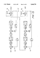
- the sigma-delta modulator of FIG. 1 is an example of a fourth-order sigma-delta modulator which is formed by connecting two, second-order sigma-delta modulators. This is similar to the fourth-order modulator described in U.S. Pat. No. 5,061,928 by Karema, et al. This modulator is characterized as a cascade of two second-order modulators. These second-order modulators are characterized as including two integrators each of which can be characterized as having the following transfer function:
- Such second-order modulators are also characterized as having a quantizer, which typically is used to quantize only the sign of the signal presented at its input. This is commonly modeled as a summing node where one input is the input to the quantizer (Q) and the other input is a noise source (E) which represents the quantization noise of the quantizer.
- Q the input to the quantizer
- E noise source
- FIG. 1 The overall transfer function of such a second-order modulator is typically given by the following equation:
- y(z) is the output of the modulator
- x(z) is the sampled input to the modulator
- E(z) is the quantization noise of the quantizer within the modulator.
- Output y 2 (z) can be characterized by the following equation:
- E 1 (z) is the quantization noise due to quantizer Q 1
- K is a constant that is frequently used as a scaling factor for the connection between the first and second modulator
- E 2 (z) is the quantization noise due to the quantizer Q 1 .
- the two modulator outputs, y 1 (z) and y 2 (z) are typically combined using a post-quantization network which results in a final modulator output y out (z).
- An appropriate post-quantization network for use with the circuit of FIG. 1 is shown in FIG. 2.
- Such a circuit along with the two, second-order sigma-delta modulators shown in FIG. 1 will result in an overall fourth-order sigma-delta modulator which may be characterized by the following equation:
- the post-quantization circuit of FIG. 2 removes the quantization noise E 1 (z) due to quantizer Q 1 . It also results in an overall fourth-order high pass filtering function on the quantization noise E 2 (z) due to quantizer Q 2 . As can be seen in the above equation, such a modulator has an overall constant group delay of four sample periods due to the z -4 term in front of the x(z) term.
- a fourth-order sigma-delta modulator is formed by connecting two, second-order sigma-delta modulators together such that only the input of the first quantizer is fed to the second, second-order sigma-delta modulator.
- the output of each quantizer for each second-order sigma-delta modulator is then fed to a post-quantization network which removes the quantization noise of the first, second-order sigma-delta modulator and shapes the quantization noise of the second, second-order sigma-delta modulator with a fourth-order high pass filter function.
- a post-quantization network which removes the quantization noise of the first, second-order sigma-delta modulator and shapes the quantization noise of the second, second-order sigma-delta modulator with a fourth-order high pass filter function.
- An example of a prior art second-order modulator having unit delays less than one is described in the IEEE Journal of Solid State Circuits, Vol. 25, no. 4, Aug. 1990, pp. 979-986, in the article entitled "The Implementation of Digital Echo Cancellation in Codecs," by Friedman, et al. Friedman describes a second-order modulator characterized as having integrators with 1/2 unit delays from input to output.
- the second-order sigma-delta modulator of Friedman is characterized as requiring two flip-flops to perform delay functions in the feedback of the modulator to obtain the desired transfer function.
- Such a second-order sigma-delta modulator is shown in FIG. 5.
- the fourth-order sigma-delta modulator of the present invention utilizes two, second-order sigma-delta modulators connected together.
- Each second-order sigma-delta modulator is characterized as including integrators with a 1/2 sample period delay from input to output.
- a second-order sigma-delta modulator including such integrators exhibits a single sample period delay from input to output.
- a fourth-order sigma-delta modulator which includes two such second-order sigma-delta modulators exhibits a delay of two sample periods from input to output.
- a fourth-order analog-to-digital converter circuit is described by combining two such second-order sigma-delta modulators which include the characteristic that all capacitors which are connected to the output of each op amp within the sigma-delta modulator would be charged on the same clock phase. Because of this characteristic, glitches between clock phases are avoided and performance of the analog-todigital converter is improved.
- the two second-order sigma-delta modulators, and a portion of the post-quantization network are constructed as a digital circuit that can be used as a digital noise shaper for a D/A converter.
- the resultant outputs of the post-quantization network may then be input into a plurality of D/A converters whose outputs are summed to form a single analog output.
- FIG. 1 is a block diagram of a fourth-order sigma-delta modulator of the prior art
- FIG. 2 is a block diagram of a post-quantization circuit of the prior art
- FIG. 3 is a block diagram of a fourth-order sigma-delta system of the prior art
- FIG. 4 is a block diagram of a post-quantization circuit of the prior art
- FIG. 5 is a block diagram of a second-order sigma-delta modulator of the prior art
- FIG. 6 is a block diagram of a second-order sigma-delta modulator of the present invention.
- FIG. 7 is an embodiment of two integrators, each having one-half unit delay
- FIG. 8 is an embodiment of two integrators, each having one unit delay
- FIG. 9 is a timing diagram of the timing signals, ⁇ 1 and ⁇ 2 , used with the switching capacitors of the present invention.
- FIG. 10 is a block diagram of a fourth-order sigma-delta modulator of the present invention.
- FIG. 11 is a block diagram of a post-quantization network of the present invention.
- FIG. 12 is a block diagram of a second-order sigma-delta modulator of the present invention.
- FIG. 13 is a block diagram of a fourth-order sigma-delta modulator of the present invention.
- FIG. 14 is an embodiment of a fourth-order sigma-delta modulator of the present invention, which utilizes summing integrators;
- FIG. 15 is a timing diagram showing the relationship between the switch capacitor timing signals, ⁇ 1 and ⁇ 2 , and the outputs y1a(z), y1b(z), y2a(z), and y2b(z), and of FIG. 14 of the present invention;
- FIG. 16 shows an alternative embodiment of an integration stage of a sigma-delta modulator of the present invention
- FIG. 17 illustrates an additional embodiment of an integration stage of a sigma-delta/modulator of the present invention
- FIG. 18 is a timing diagram showing the timing of the switches in the sigma-delta embodiment illustrated in FIG. 19;
- FIG. 19 is an embodiment of an integration stage of a sigma-delta modulator of the present invention.
- FIG. 20 is a graphic illustration of a plot of simulated signal noise plus distortion ratio levels (SNDR), with an oversampling ratio of 64, of a sigma-delta modulator of the present invention.
- FIG. 21 is a post-quantization network for a D/A modulator of the present invention.
- FIG. 6 is a functional block diagram of a second-order sigma-delta modulator 5 of the present invention. Integrators 12 and 14, each having a 1/2 unit delay with the following transfer function, are utilized:
- FIG. 7 schematically depicts a single-ended implementation of two integrators in series with half unit delays in each integrator.
- FIG. 8 is a single-ended implementation of two integrators in series with unit delays in each integrator.
- ⁇ 1 and ⁇ 2 are two-phase non-overlapping clocks and are characterized such that neither clock is at a logic ⁇ 1 ⁇ during the same instant in time.
- An example of such clocks is shown in FIG. 9.
- ⁇ 1 is at a logic ⁇ 1 ⁇ any switch which is denoted as being controlled by ⁇ 1 is closed. Such a switch is open at all other times.
- ⁇ 2 is at a logic ⁇ 1 ⁇ any switch is denoted as being controlled by ⁇ 2 is closed. Such a switch is open at all other times.
- capacitor 24 and capacitor 22 are charging on the same clock phase. Because of this, op amp output node 28 does not glitch between clock phases. Such a structure may have the added benefit of increased performance when used in a sigma-delta modulator which is configured as an A/D converter circuit.
- Equation A E(z) represents the quantization noise of a quantizer Q 1 modelled as a summing node 30 in FIG. 6, where y(z) represents the output signal 6 of modulator 5 and x(z) represents a sampled analog input signal 7.
- y(z) can be represented by the following equation
- the desired transfer function there would be a delay of 1/2 of a sample period from the output of the quantizer Q 1 to the input of the gain of 2 block 8.
- FIG. 10 illustrates the functional block diagram implementation of the current invention illustrated by a fourth-order sigma-delta modulator 9 formed by connecting together two, second-order sigma-delta modulators 11 and 13, each including 1/2 unit delay integrators associated therewith.
- the output signal 15, y 1 (z), in FIG. 10 is represented by the following equation:
- E 1 (z) is removed in equations for y 1 (z) and y 2 (z) so the following desired fourth-order output equation of the fourth-order modulator, as shown in FIG. 10, is achieved.
- Equation y 1 (z) is then multiplied by the term z -1 which yields equation y 6 , as follows:
- equation y 5 (z) is added to equation y 6 (z) yielding the desired equation for y out (z), as follows:
- FIG. 11 illustrates the post-quantization network 23 which corresponds to the aforementioned equations that results in the above equation for y out (z), 21.
- Output signals 15 and 17, y 1 (z) and y 2 (z) from FIG. 10 are connected to y 1 (z) and y 2 (z), respectively, in FIG. 11.
- the output signal 21, y out (z), in FIG. 11 is available as an input signal to additional circuitry, such as a decimator filter.
- FIG. 12 illustrates how scaling is employed in the design of the second-order modulator 25 to prevent the integrators 36 and 38 from clipping, while not affecting the transfer function of the second-order sigma-delta modulator 25.
- the scaling is accomplished by using constants K 1 and K 2 .
- the integrator in FIG. 12 is shown within the dashed area 36, which includes summing node 10, 1/2 unit delay integrator block 12 and a scaling factor 1/K 1 .
- the other integrator in FIG. 12 shown within the dashed area 38 includes summing node 18, 1/2 unit delay integrator block 14, and constants K 1 , 1/K 2 and 2.
- 1/K 1 in integrator 36 is compensated by factor K 1 in integrator 38, no net change occurs in the transfer function due to scaling factor 1/K 1 .
- the quantizer Q 1 denoted by summing node 19, with noise E 1 (z) as an input, is typically a comparator which quantizes only the sign of the signal input to it.
- the term 1/K 2 can be of arbitrary size and will not affect the transfer function of the second-order sigma-delta modulator 25.
- FIG. 14 depicts an embodiment of the analog portion of the fourth-order sigma-delta A/D converter of the present invention.
- the implementation shown is a single ended configuration. If output signal CMP 1 is a logic ⁇ 1 ⁇ and output signal CMP 1 * is a logic ⁇ 0 ⁇ , then negative reference voltage DNEG is selected as an input to the summing integrator 40 and positive reference voltage DPOS is selected as an input to the summing integrator 41. If output signal CMP 1 is a logic ⁇ 0 ⁇ and output signal CMP 1 * is a logic ⁇ 1 ⁇ then reference voltage DPOS is selected as an input to the summing integrator 40 and reference voltage DNEG is selected as an input to the summing integrator 41.
- output signal CMP 2 is a logic ⁇ 1 ⁇ and output signal CMP 2 * is a logic ⁇ 0 ⁇ then reference voltage DNEG is selected as an input to the summing integrator 42 and reference voltage DPOS is selected as an input to the summing integrator 43.
- reference voltage DPOS is selected as an input to the summing integrator 42 and reference voltage DNEG is selected as an input to the summing integrator 43.
- FIG. 15 is a timing diagram illustrating the timing relationships between the following signals which are shown in FIG. 14: ⁇ 1 , ⁇ 2 , the output y 1 a(z) of integrator 40, the output y 1 b(z) of integrator 41, the output y 2 a(z) of integrator 42, and the output y 2 b(z) of integrator 43.
- the transfer function of summing integrator 40 in FIG. 14 can be represented by the following equation:
- the output y 1 (z), which is essentially y 1 b(z) that has been sampled during the ⁇ 2 , can be represented by the following equation:
- y 1 (z) is the output of comparator 47
- x(z) is the sampled analog input to the sigma-delta modulator
- E 1 (z) is the quantization noise due to comparator 47.
- a preferred method of implementing the analog portion of the architecture is to utilize fully differential design techniques.
- Examples of differential differencing integrators which may replace the summing integrators 40-43 shown in FIG. 14, are shown in FIGS. 16 and 17.
- the timing shown in FIGS. 16 and 17 is preferred where the differential differencing integrators shown therein replace summing integrators 40 and 42 in FIG. 14.
- the integrators of FIGS. 16 and 17 are substituted for integrators 41 and 43 in FIG. 14, the clocks ⁇ 1 and ⁇ 2 shown within hashed area A of FIGS. 16 and 17 are reversed (i.e., ⁇ 1 clocks become ⁇ 2 and vice versa).
- integrators have been described in the literature, including correlated-double-sampled and chopper stabilized integrators. These techniques may also be used to implement the aforementioned integrators. Three-phase clocking may also be employed which would allow both the input signal and the DPOS/DNEG signals to be double-sampled.
- clock phases ⁇ 1 and ⁇ 2 can be implemented as four clocks, as shown in FIG. 18. This technique is described by Kuang-Lu Lee and Robert G. Meyer, IEEE JSSC, December 1985, Vol. SC-20, No. 6, pp. 1103-1113, entitled, Low-Distortion Switched Capacitor Filter Design Techniques, incorporated herein for all purposes.
- switches controlled by S 3 open slightly before switches controlled by S 1 and switches controlled by S 4 open slightly before switches controlled by S 2 .
- switches controlled by S 3 open charge is injected onto capacitors C 1 A and C 1 B. Since switches controlled by S 3 previously connected one plate of C 1 A and one plate of C 1 B to a reference point, the charge that is injected due to switches controlled by S 1 opening is not input signal dependent.
- switches controlled by S 1 open capacitors C 1 A and C 1 B already have one plate floating. Thus, the action of switches controlled by S 1 cannot inject charge onto C 1 A or C 1 B.
- Zero dB is defined as a full-scale input voltage which is one-half the D/A converter reference voltage, which for a differential implementation of FIGS. 16 and 17 would be the voltage defined by DPOS-DNEG.
- the invention disclosed herein may be used as a digital noise shaper for a D/A converter implementation.
- the two second-order sigma-delta modulators which are connected together in FIG. 10 would be implemented as digital circuitry comprised of appropriate adders, subtractors, accumulators, multipliers, and quantizers.
- the post-quantizer circuitry shown in FIG. 11 would be modified as shown in FIG. 21.
- Digital signal y 6 (z) would be converted to an analog signal by D/A converter 32.
- digital signal y 5 (z) would be converted to an analog signal by D/A converter 34.
- the resultant signals, y 6 a(z) and y 5 a(z) respectively would then be summed together by an analog summing node 72.
- the quantizer Q 1 in the second-order sigma-delta modulator 11 shown in FIG. 10 quantizes only the sign of the signal input to it, signal y 1 (z), and thus signal y 6 (z), of FIG. 21 would be represented by a 1-bit digital signal.
- a D/A converter which converts a 1-bit digital signal to an analog signal would result in an analog signal with only two output voltage, or current levels, possible. Such a D/A converter would be inherently linear and thus would contribute no distortion terms to the final analog signal, y out (2).
- signal y 2 (z) would also be represented by a 1-bit digital signal.
- signal y 5 (z) would be represented by a plurality of bits for any value of C greater than one.
- the D/A converter 34 would convert a signal represented by a plurality of bits to an analog signal would have a plurality of possible output voltages, or currents, which correspond to any possible code represented by y 5 (z).
- signal y 5 (z) can be represented by the following equation:
- y 5 (z) contains no terms which represent the input signal, x(z).
- the D/A converter 34 in FIG. 21 will add no terms which would cause harmonic distortion in the final output signal y out if there are any nonidealities in the D/A converter 34.
- signal y 5 a(z) may be represented by the following equation:
- R is a term which represents any nonidealities, or nonlinearities, in D/A converter 34 in FIG. 21. If D/A converter 32 in FIG. 21 is ideal, then the following equation would represent y 6 a(z):
- the final output signal, y out (z) would then be the sum of y 5 a(z) and y 6 a(z) and would be represented by the following equation:
Abstract
Description
H(z)=z.sup.-1 /(1-z.sup.-1)
y(z)=z.sup.-2 x(z)+E(z)(1-z.sup.-1).sup.2
y.sub.1 (z)=z.sup.-2 x(z)+E.sub.1 (z)(1-z.sup.-1).sup.2
y.sub.2 (z)=z.sup.-2 E.sub.1 (z)+KE.sub.2 (z)(1-z.sup.-1).sup.2
y.sub.out (z)=z.sup.-4 x(z)+KE.sub.2 (z)(1-z.sup.-1).sup.4
H.sub.1 (z)=z.sup.-1/2 /(1-z.sup.-1)
H.sub.2 (z)=z.sup.-1 /(1-z.sup.-1)
y(z)=z.sup.-1 x(z)+E(z)(1-z.sup.-1).sup.2 Equation A
y(z)=E(z)+C(z)Equation 1
C(z)={z.sup.-1 x(z)-y(z)[z.sup.-(Q+1) +2z.sup.-(P+1/2) -2z.sup.-(P+3/2) ]/(1-z.sup.-1).sup.2 } Equation 2
y(z)(1-z.sup.-1).sup.2 =E(1-z.sup.-1).sup.2 +z.sup.-1 x(z)-y(z)[z.sup.-(Q+1) +2z.sup.-(P+1/2) -2z.sup.-(P+3/2) ]
y(z)[1-2z.sup.-1 +z.sup.-2 +z.sup.-(Q+1) +2z.sup.-(P+1/2) -2z.sup.-(P+3/2) ]=z.sup.-1 x(z)+E(z)(1-z.sup.-1).sup.2
1-2z.sup.-1 +z.sup.-2 +z.sup.-(Q+1) +2z.sup.(P+1/2) -2z.sup.-(P+3/2) =1
-2z.sup.-1 +z.sup.-2 +z.sup.-(Q+1) +2z.sup.-(P+1/2) -2z.sup.-(P+3/2) =0
y.sub.1 (z)=z.sup.-1 x(z)+E.sub.1 (z)(1-z.sup.-1).sup.2
y.sub.2 (z)=(1/ C)z.sup.-1 y.sub.1 (z)-(1/C)z.sup.-1 E.sub.1 (z)
y.sub.out (z)=z.sup.-2 x(z)+CE.sub.2 (z)(1-z.sup.-1).sup.4
y.sub.3 (z)=z.sup.-1 y1(z)-z.sup.-1 E.sub.1 (z)+CE.sub.2 (z)(1-z.sup.-1).sup.2
y.sub.4 (z)=-z.sup.-1 E.sub.1 (z)+CE.sub.2 (z)(1-z.sup.-1).sup.2
y.sub.5 (z)=-z.sup.-1 (1-z.sup.-1).sup.2 E.sub.1 (z)+C(1-z.sup.-1).sup.4 E.sub.2 (z)
y.sub.6 (z)=z.sup.-2 x(z)+z.sup.-1 E.sub.1 (z)(1-z.sup.-1).sup.2
y.sub.out (z)=z.sup.-2 x(z)+CE.sub.2 (z)(1-z.sup.-1).sup.4
y.sub.1 a(z)=[(C.sub.1 /C.sub.3)x(z)-z.sup.-1 (C.sub.2 /C.sub.3)y.sub.1 (z)]z.sup.-1/2 /(1-z.sup.-1)
y.sub.1 (z)=[(C.sub.4 /C.sub.6)y.sub.1 a(z)-(C.sub.5 /C.sub.6)z.sup.-1/2 y.sub.1 (z)]z-1/2/(1-z.sup.-1)
y.sub.1 d.sub.1 (z)=(1/K.sub.1)[x(z)-z.sup.-1 y.sub.2 d.sub.1 (z)]z.sup.-1/2 (1-z.sup.-1)
y.sub.2 d.sub.1 (z)=[(K.sub.1 /K.sub.2)y.sub.1 d(z)-(2/K.sub.2)z.sup.-1/2 y.sub.2 d.sub.1 (z)]z.sup.-1/2 /(1-z.sup.-1)
y.sub.1 (z)=z.sup.-1 x(z)+E.sub.1 (z)(1-z.sup.-1).sup.2
y.sub.5 (z)=-z.sup.-1 (1-z.sup.-1).sup.2 E.sub.1 (z)+C(1-z.sup.-1).sup.4 E.sub.2 (z)
y.sub.5 a(z)=R[-z.sup.-1 (1-z.sup.-1).sup.2 E.sub.1 (z)+C(1-z.sup.-1).sup.4 E.sub.2 (z)]
y.sub.6 a(z)=z.sup.-2 x(z)+z.sup.-1 E.sub.1 (z)(1-z.sup.-1).sup.2
y.sub.out (z)=z.sup.-2 x(z)+E.sub.1 (z)z.sup.-1 (1-z.sup.-1).sup.2 (1-R)+RCE.sub.2 (z)(1-z.sup.-1).sup.4
Claims (11)
Priority Applications (5)
| Application Number | Priority Date | Filing Date | Title |
|---|---|---|---|
| US08/352,665 US5648779A (en) | 1994-12-09 | 1994-12-09 | Sigma-delta modulator having reduced delay from input to output |
| EP95942400A EP0796525B1 (en) | 1994-12-09 | 1995-11-02 | Sigma-delta modulator with reduced delay from input to output |
| DE69520048T DE69520048T2 (en) | 1994-12-09 | 1995-11-02 | SIGMA DELTA MODULATOR WITH REDUCED DELAY FROM INPUT TO OUTPUT |
| PCT/US1995/014357 WO1996018242A1 (en) | 1994-12-09 | 1995-11-02 | Sigma-delta modulator with reduced delay from input to output |
| JP51758496A JP3452200B2 (en) | 1994-12-09 | 1995-11-02 | Sigma-delta modulator with reduced input to output delay |
Applications Claiming Priority (1)
| Application Number | Priority Date | Filing Date | Title |
|---|---|---|---|
| US08/352,665 US5648779A (en) | 1994-12-09 | 1994-12-09 | Sigma-delta modulator having reduced delay from input to output |
Publications (1)
| Publication Number | Publication Date |
|---|---|
| US5648779A true US5648779A (en) | 1997-07-15 |
Family
ID=23386002
Family Applications (1)
| Application Number | Title | Priority Date | Filing Date |
|---|---|---|---|
| US08/352,665 Expired - Lifetime US5648779A (en) | 1994-12-09 | 1994-12-09 | Sigma-delta modulator having reduced delay from input to output |
Country Status (5)
| Country | Link |
|---|---|
| US (1) | US5648779A (en) |
| EP (1) | EP0796525B1 (en) |
| JP (1) | JP3452200B2 (en) |
| DE (1) | DE69520048T2 (en) |
| WO (1) | WO1996018242A1 (en) |
Cited By (27)
| Publication number | Priority date | Publication date | Assignee | Title |
|---|---|---|---|---|
| WO1998048515A1 (en) * | 1997-04-18 | 1998-10-29 | Steensgaard Madsen Jesper | Oversampled digital-to-analog converter based on nonlinear separation and linear recombination |
| US5949361A (en) * | 1997-05-12 | 1999-09-07 | The United States Of America Represented By The Secretary Of The Navy | Multi-stage delta sigma modulator with one or more high order sections |
| US6061008A (en) * | 1997-12-19 | 2000-05-09 | Rockwell Science Center, Inc. | Sigma-delta-sigma modulator for high performance analog-to-digital and digital-to-analog conversion |
| WO2001011785A2 (en) * | 1999-08-06 | 2001-02-15 | Siemens Aktiengesellschaft | Cascade sigma-delta modulator |
| US20020121994A1 (en) * | 2001-01-09 | 2002-09-05 | Bolton Jerry Thomas | Delta-sigma modulator system and method |
| US6496128B2 (en) * | 1999-05-05 | 2002-12-17 | Infineon Technologies Ag | Sigma-delta analog-to-digital converter array |
| WO2002103609A1 (en) * | 2001-06-15 | 2002-12-27 | Analog Devices, Inc. | A variable modulus interpolator, and a variable frequency synthesiser incorporating the variable modulus interpolator |
| US20030039319A1 (en) * | 2001-08-22 | 2003-02-27 | Willem Engelse | Monitoring upstream frequency band |
| US20030038660A1 (en) * | 2001-08-22 | 2003-02-27 | Paul Dormitzer | Compensating for differences between clock signals |
| WO2003019786A2 (en) * | 2001-08-22 | 2003-03-06 | Adc Broadband Access Systems, Inc. | Digital down converter |
| US6535154B1 (en) * | 2001-11-05 | 2003-03-18 | Texas Instruments Incorporated | Enhanced noise-shaped quasi-dynamic-element-matching technique |
| WO2003028218A1 (en) * | 2001-09-26 | 2003-04-03 | Ashvattha Semiconductor, Inc. | Fractional-n type frequency synthesizer |
| US6608575B2 (en) * | 2001-01-31 | 2003-08-19 | Qualcomm Incorporated | Hybrid multi-stage circuit |
| WO2003077424A1 (en) * | 2002-03-08 | 2003-09-18 | Zarlink Semiconductor (U.S.) Inc. | Delta-sigma modulator with feed-forward path |
| KR20040016127A (en) * | 2002-08-16 | 2004-02-21 | 한건희 | Time-interleaved band-pass Δ-∑ modulator |
| US6816100B1 (en) | 1999-03-12 | 2004-11-09 | The Regents Of The University Of California | Analog-to-digital converters with common-mode rejection dynamic element matching, including as used in delta-sigma modulators |
| US20040233091A1 (en) * | 2003-05-23 | 2004-11-25 | Patrick Clement | Analog to digital converter |
| US20050162887A1 (en) * | 2000-02-18 | 2005-07-28 | Sony Corporation | Digital signal processing device, a method and a delta-sigma modulator using the same method |
| US20060071834A1 (en) * | 2004-09-10 | 2006-04-06 | Del Mar Charmarro Marti Maria | Feedback DAC chopper stabilization in a CT single ended multi-bit sigma delta ADC |
| US20070210947A1 (en) * | 2006-03-10 | 2007-09-13 | Portal Player, Inc. | Method and apparatus for adc size and performance optimization |
| US20070252736A1 (en) * | 2005-05-19 | 2007-11-01 | Neaz Farooqi | Low power sigma delta modulator |
| US7398065B1 (en) | 2004-08-31 | 2008-07-08 | Rockwell Collins, Inc. | Programmable sampling band pass filter |
| US20080272944A1 (en) * | 2007-05-03 | 2008-11-06 | Texas Instruments Incorporated | Feed-forward circuitry and corresponding error cancellation circuit for cascaded delta-sigma modulator |
| US20120326905A1 (en) * | 2009-12-29 | 2012-12-27 | Thine Electronics, Inc. | Sigma-delta modulator |
| TWI620417B (en) * | 2013-08-20 | 2018-04-01 | 西凱渥資訊處理科技公司 | Dither-less multi-stage noise shaping fractional-n frequency synthesizer systems and methods |
| US20220045691A1 (en) * | 2020-08-10 | 2022-02-10 | Analog Devices, Inc. | System and method to compensate for feedback delays in digital class-d modulators |
| US11621722B2 (en) * | 2021-08-27 | 2023-04-04 | Analog Devices, Inc. | Multi quantizer loops for delta-sigma converters |
Families Citing this family (1)
| Publication number | Priority date | Publication date | Assignee | Title |
|---|---|---|---|---|
| JP4302672B2 (en) * | 2005-07-14 | 2009-07-29 | シャープ株式会社 | AD converter |
Citations (33)
| Publication number | Priority date | Publication date | Assignee | Title |
|---|---|---|---|---|
| EP0104988A1 (en) * | 1982-09-21 | 1984-04-04 | Patrice Senn | Double integration delta-sigma encoder and use of this encoder in a PCM transmission path and in the measuring of DC voltages |
| US4590457A (en) * | 1983-12-20 | 1986-05-20 | American Microsystems, Inc. | Digital to analog converter utilizing pulse width modulation |
| US4704600A (en) * | 1985-02-04 | 1987-11-03 | Nippon Telegraph And Telephone Corporation | Oversampling converter |
| US4849662A (en) * | 1986-04-14 | 1989-07-18 | Crystal Semiconductor Corporation | Switched-capacitor filter having digitally-programmable capacitive element |
| US4851841A (en) * | 1987-10-02 | 1989-07-25 | Crystal Semiconductor Corporation | Gain scaling of oversampled analog-to-digital converters |
| EP0328318A2 (en) * | 1988-02-10 | 1989-08-16 | Fujitsu Limited | Delta-sigma modulator |
| US4876542A (en) * | 1988-01-25 | 1989-10-24 | Motorola, Inc. | Multiple output oversampling A/D converter with each output containing data and noise |
| US4918454A (en) * | 1988-10-13 | 1990-04-17 | Crystal Semiconductor Corporation | Compensated capacitors for switched capacitor input of an analog-to-digital converter |
| US4939516A (en) * | 1988-06-13 | 1990-07-03 | Crystal Semiconductor | Chopper stabilized delta-sigma analog-to-digital converter |
| US5039989A (en) * | 1989-10-27 | 1991-08-13 | Crystal Semiconductor Corporation | Delta-sigma analog-to-digital converter with chopper stabilization at the sampling frequency |
| US5055843A (en) * | 1990-01-31 | 1991-10-08 | Analog Devices, Inc. | Sigma delta modulator with distributed prefiltering and feedback |
| EP0450947A2 (en) * | 1990-04-06 | 1991-10-09 | General Electric Company | Analog-to-digital converter |
| US5061928A (en) * | 1988-11-09 | 1991-10-29 | Oy Nokia Ab | System and method of scaling error signals of caseload second order modulators |
| US5068660A (en) * | 1989-10-27 | 1991-11-26 | Crystal Semiconductor Corporation | Combining fully-differential and single-ended signal processing in a delta-sigma modulator |
| US5068661A (en) * | 1987-09-14 | 1991-11-26 | Matsushita Electric Industrial Co., Ltd. | Multi-stage noise shaping over-sampling d/a converter |
| US5079550A (en) * | 1989-10-27 | 1992-01-07 | Crystal Semiconductor Corporation | Combining continuous time and discrete time signal processing in a delta-sigma modulator |
| US5084702A (en) * | 1990-11-01 | 1992-01-28 | General Electric Company | Plural-order sigma-delta analog-to-digital converter using both single-bit and multiple-bit quantizers |
| US5103229A (en) * | 1990-04-23 | 1992-04-07 | General Electric Company | Plural-order sigma-delta analog-to-digital converters using both single-bit and multiple-bit quantization |
| US5148166A (en) * | 1990-04-06 | 1992-09-15 | General Electric Company | Third order sigma delta oversampled analog-to-digital converter network with low component sensitivity |
| US5148167A (en) * | 1990-04-06 | 1992-09-15 | General Electric Company | Sigma-delta oversampled analog-to-digital converter network with chopper stabilization |
| US5153593A (en) * | 1990-04-26 | 1992-10-06 | Hughes Aircraft Company | Multi-stage sigma-delta analog-to-digital converter |
| US5157395A (en) * | 1991-03-04 | 1992-10-20 | Crystal Semiconductor Corporation | Variable decimation architecture for a delta-sigma analog-to-digital converter |
| US5162799A (en) * | 1990-11-30 | 1992-11-10 | Kabushiki Kaisha Toshiba | A/d (analog-to-digital) converter |
| US5184130A (en) * | 1991-02-08 | 1993-02-02 | Analog Devices, Incorporated | Multi-stage A/D converter |
| US5189419A (en) * | 1990-05-21 | 1993-02-23 | University College Cork | Single shot sigma-delta analog to digital converter |
| US5198817A (en) * | 1990-04-26 | 1993-03-30 | Hughes Aircraft Company | High-order sigma-delta analog-to-digital converter |
| US5208597A (en) * | 1988-10-13 | 1993-05-04 | Crystal Semiconductor | Compensated capacitors for switched capacitor input of an analog-to-digital converter |
| US5210537A (en) * | 1991-02-08 | 1993-05-11 | Analog Devices, Incorporated | Multi-stage A/D converter |
| US5274375A (en) * | 1992-04-17 | 1993-12-28 | Crystal Semiconductor Corporation | Delta-sigma modulator for an analog-to-digital converter with low thermal noise performance |
| US5283578A (en) * | 1992-11-16 | 1994-02-01 | General Electric Company | Multistage bandpass Δ Σ modulators and analog-to-digital converters |
| EP0586021A1 (en) * | 1990-01-31 | 1994-03-09 | Analog Devices, Inc. | Digital noise shaper circuit |
| US5298900A (en) * | 1992-03-12 | 1994-03-29 | Siemens Aktiengesellschaft | Sigma-delta modulator |
| US5442354A (en) * | 1993-08-26 | 1995-08-15 | Advanced Micro Devices, Inc. | Fourth-order cascaded sigma-delta modulator |
-
1994
- 1994-12-09 US US08/352,665 patent/US5648779A/en not_active Expired - Lifetime
-
1995
- 1995-11-02 JP JP51758496A patent/JP3452200B2/en not_active Expired - Fee Related
- 1995-11-02 EP EP95942400A patent/EP0796525B1/en not_active Expired - Lifetime
- 1995-11-02 DE DE69520048T patent/DE69520048T2/en not_active Expired - Lifetime
- 1995-11-02 WO PCT/US1995/014357 patent/WO1996018242A1/en active IP Right Grant
Patent Citations (38)
| Publication number | Priority date | Publication date | Assignee | Title |
|---|---|---|---|---|
| EP0104988A1 (en) * | 1982-09-21 | 1984-04-04 | Patrice Senn | Double integration delta-sigma encoder and use of this encoder in a PCM transmission path and in the measuring of DC voltages |
| US4590457A (en) * | 1983-12-20 | 1986-05-20 | American Microsystems, Inc. | Digital to analog converter utilizing pulse width modulation |
| US4704600A (en) * | 1985-02-04 | 1987-11-03 | Nippon Telegraph And Telephone Corporation | Oversampling converter |
| US4849662A (en) * | 1986-04-14 | 1989-07-18 | Crystal Semiconductor Corporation | Switched-capacitor filter having digitally-programmable capacitive element |
| US5068661A (en) * | 1987-09-14 | 1991-11-26 | Matsushita Electric Industrial Co., Ltd. | Multi-stage noise shaping over-sampling d/a converter |
| US4851841A (en) * | 1987-10-02 | 1989-07-25 | Crystal Semiconductor Corporation | Gain scaling of oversampled analog-to-digital converters |
| US4876542A (en) * | 1988-01-25 | 1989-10-24 | Motorola, Inc. | Multiple output oversampling A/D converter with each output containing data and noise |
| US4920544A (en) * | 1988-02-10 | 1990-04-24 | Fujitsu Limited | Delta-sigma modulator |
| EP0328318A2 (en) * | 1988-02-10 | 1989-08-16 | Fujitsu Limited | Delta-sigma modulator |
| US4939516A (en) * | 1988-06-13 | 1990-07-03 | Crystal Semiconductor | Chopper stabilized delta-sigma analog-to-digital converter |
| US4939516B1 (en) * | 1988-06-13 | 1993-10-26 | Crystal Semiconductor Corporation | Chopper stabilized delta-sigma analog-to-digital converter |
| US4918454A (en) * | 1988-10-13 | 1990-04-17 | Crystal Semiconductor Corporation | Compensated capacitors for switched capacitor input of an analog-to-digital converter |
| US5208597A (en) * | 1988-10-13 | 1993-05-04 | Crystal Semiconductor | Compensated capacitors for switched capacitor input of an analog-to-digital converter |
| US4918454B1 (en) * | 1988-10-13 | 1994-02-22 | Crystal Semiconductor Corporation | |
| US5061928A (en) * | 1988-11-09 | 1991-10-29 | Oy Nokia Ab | System and method of scaling error signals of caseload second order modulators |
| US5039989A (en) * | 1989-10-27 | 1991-08-13 | Crystal Semiconductor Corporation | Delta-sigma analog-to-digital converter with chopper stabilization at the sampling frequency |
| US5068660A (en) * | 1989-10-27 | 1991-11-26 | Crystal Semiconductor Corporation | Combining fully-differential and single-ended signal processing in a delta-sigma modulator |
| US5079550A (en) * | 1989-10-27 | 1992-01-07 | Crystal Semiconductor Corporation | Combining continuous time and discrete time signal processing in a delta-sigma modulator |
| US5311181A (en) * | 1990-01-31 | 1994-05-10 | Analog Devices, Inc. | Sigma delta modulator |
| EP0586021A1 (en) * | 1990-01-31 | 1994-03-09 | Analog Devices, Inc. | Digital noise shaper circuit |
| US5055843A (en) * | 1990-01-31 | 1991-10-08 | Analog Devices, Inc. | Sigma delta modulator with distributed prefiltering and feedback |
| US5148166A (en) * | 1990-04-06 | 1992-09-15 | General Electric Company | Third order sigma delta oversampled analog-to-digital converter network with low component sensitivity |
| US5148167A (en) * | 1990-04-06 | 1992-09-15 | General Electric Company | Sigma-delta oversampled analog-to-digital converter network with chopper stabilization |
| US5065157A (en) * | 1990-04-06 | 1991-11-12 | General Electric Company | High order sigma delta oversampled analog-to-digital converter integrated circuit network with minimal power dissipation and chip area requirements |
| EP0450947A2 (en) * | 1990-04-06 | 1991-10-09 | General Electric Company | Analog-to-digital converter |
| US5103229A (en) * | 1990-04-23 | 1992-04-07 | General Electric Company | Plural-order sigma-delta analog-to-digital converters using both single-bit and multiple-bit quantization |
| US5198817A (en) * | 1990-04-26 | 1993-03-30 | Hughes Aircraft Company | High-order sigma-delta analog-to-digital converter |
| US5153593A (en) * | 1990-04-26 | 1992-10-06 | Hughes Aircraft Company | Multi-stage sigma-delta analog-to-digital converter |
| US5189419A (en) * | 1990-05-21 | 1993-02-23 | University College Cork | Single shot sigma-delta analog to digital converter |
| US5084702A (en) * | 1990-11-01 | 1992-01-28 | General Electric Company | Plural-order sigma-delta analog-to-digital converter using both single-bit and multiple-bit quantizers |
| US5162799A (en) * | 1990-11-30 | 1992-11-10 | Kabushiki Kaisha Toshiba | A/d (analog-to-digital) converter |
| US5184130A (en) * | 1991-02-08 | 1993-02-02 | Analog Devices, Incorporated | Multi-stage A/D converter |
| US5210537A (en) * | 1991-02-08 | 1993-05-11 | Analog Devices, Incorporated | Multi-stage A/D converter |
| US5157395A (en) * | 1991-03-04 | 1992-10-20 | Crystal Semiconductor Corporation | Variable decimation architecture for a delta-sigma analog-to-digital converter |
| US5298900A (en) * | 1992-03-12 | 1994-03-29 | Siemens Aktiengesellschaft | Sigma-delta modulator |
| US5274375A (en) * | 1992-04-17 | 1993-12-28 | Crystal Semiconductor Corporation | Delta-sigma modulator for an analog-to-digital converter with low thermal noise performance |
| US5283578A (en) * | 1992-11-16 | 1994-02-01 | General Electric Company | Multistage bandpass Δ Σ modulators and analog-to-digital converters |
| US5442354A (en) * | 1993-08-26 | 1995-08-15 | Advanced Micro Devices, Inc. | Fourth-order cascaded sigma-delta modulator |
Non-Patent Citations (64)
| Title |
|---|
| "A 120dB Linear Switched-Capacitor Delta-Sigma Modulator," Donald A. Kerth, et al., 1994 IEEE International Solid-State Circuits Conference, Digest of Technical Papers, TP 11.6, pp. 196-197, ISSCC94/Thursday, Feb. 17, 1994/Sea Cliff. |
| "A 12-Bit Successive-Approximation-Type ADC with Digital Error Correction," Kanit Bacrania, IEEE Journal of Solid-State Circuits, vol. SC-21, No. 6, Dec. 1986. |
| "A 16b Oversampling A/D Conversion Technology using Triple Integration Noise Shaping," Yasuyuki Matsuya, et al., 1987 IEEE International Solid-State Circuits Conference, ISSCC 87/Wednesday, Feb. 25, 1987/Trianon Ballroom, pp. 48-50. |
| "A 192ks/s Sigma-Delta ADC with Integrated Decimation Filters Providing -97.4dB THD," Mark A. Alexander, et al., ISSCC94/Session 11/Oversampled Data Coversion/Paper TP 11.3, 1994 IEEE International Solid-State Circuits Conference. |
| "A 3-μm CMOS Digital Codec with Programmable Echo Cancellation and Gain Setting," Paul Defraeye, et al., IEEE Journal of Solid-State Circuits, vol. SC-20, No. 3, Jun. 1985, pp. 679-687. |
| "A Comparison of Modulator Networks for High-Order Oversampled ΣΔ Analog-to-Digital Converters," D. B. Ribner, IEEE Transactions on Circuits and Systems, (1991) Feb., No. 2, pp. 145-159. |
| "A Digitally-Corrected 20b Delta-Sigma Modulator," Charles D. Thompson, et al., 1994 IEEE International Solid-State Circuits Conference, ISSCC94/Session 11/Oversampled Data Conversion/Paper TP 11.5, pp. 194-195. |
| "A Monolithic 50 KHz 16-Bit A/D-D/A Converter Using Sigma-Delta Modulation," Charles D. Thompson, et al., Digital Signal Processor Operation/Motorola, Inc. 1990 IEEE. |
| "A Multistage Delta-Sigma Modulator without Double Integration Loop," Toshio Hayashi, et al., 1986 IEEE International Solid-State Circuits Conference, ISSCC 86/Thursday, Feb. 20, 1986/California Pavilion C, pp. 182-183. |
| "A Per-Channel A/D Converter Having 15-Segment μ-255 Companding," James C. Candy, et al., IEEE Transactions on Communications, vol. COM-24, Jan. 1976. |
| "A Self-Calibrating 15 Bit CMOS A/D Converter," Hae-Seung Lee et al.; IEEE Journal of Solid State Circuits, vol. SC-19, No. 6, Dec. 1984. |
| "A Stereo 97dB SNR Audio Sigma-Delta ADC," Tapani Ritoniemi, et al., 1994 IEEE International Solid-State Circuits Conference, ISSCC94/Session 11/Oversampled Data Conversion/Paper TP 11.7, pp. 198-199. |
| "A Third-Order Cascaded Sigma-Delta Modulators," Louis A. Williams III et al., IEEE Transactions on Circuits and Systems, 38 (1991) May, No. 5, New York, pp. 489-497. |
| "A Voiceband Codec with Digital Filtering," James C. Candy, et al., IEEE Transactions on Communications, vol. COM-29, No. 6, Jun. 1981, pp. 815-829. |
| "An Economical Class of Digital Filters for Decimation and Interpolation," Eugene B. Hogenauer., IEEE Transactions on Acoustics, Speech, and Signal Processing, vol. ASSP-29, No. 2, Apr. 1981, pp. 155-162. |
| "Area-Efficient Multichannel Oversampled PCM Voice-Band Coder," Bosco H. Leung, et al., IEEE Journal of Solid-State Circuits, vol. 23, No. 6, Dec. 1988, pp. 1351-1357. |
| "Circuit and Technology Considerations for MOS Delta-Sigma A/D Converters," Max W. Hauser et al., 1986 IEEE, pp. 1310-1315. |
| "Decimation for Sigma Delta Modulation," James C. Candy, IEEE Transactions on Communications, vol. COM-34, No. 1, Jan. 1986, pp. 72-76. |
| "Design and Implementation of Digital FIR Filters," P. P. Vaidyanathan, Chapter 2 in Handbook of DSP Engineering Applications, D. F. Elliott, editor, Academic Press, 1987. |
| "Design of Stable High Order 1-Bit Sigma-Delta Modulators," Tapani Ritoniemi, et al., Signal Processing Laboratory, Tampere University of Technology, reprinted from IEEE Proc. ISCAS '90, pp. 3267-3270, May 1990. |
| "Fourth Order Sigma-Delta Modulator Circuit for Digital Audio and ISDN Applications," T. Karema, et al., Tampere University of Technology, Finland, pp. 223-227. |
| "Low-Distortion Switched-Capacitor Filter Design Techniques," Kuang-Lu Lee, et al., IEEE Journal of Solid-State Circuits, vol. SC-20, No. 6, Dec. 1985, pp. 1103-1113. |
| "Multirate Digital Filters, Filter Banks, Polyphase Networks, and Applications: A Tutorial," P. P. Vaidyanathan, Proceedings of the IEEE, vol. 78, No. 1, Jan. 1990, pp. 56-93. |
| "Multirate Filter Designs Using Comb Filters," Shuni Chu, et al., IEEE Transactions on Circuits and Systems, vol. CAS-31, No. 11, Nov. 1984, pp. 913-924. |
| "Reduction of Quantizing Noise by Use of Feedback," H. A. Spang, III, and P. M. Schultheiss, reprinted from IRE Trans. Commun. Systems, pp. 373-380, Dec. 1962. |
| "Switched-Capacitor Second-Order Noise-Shaping Coder," G. Lainey, et al., Electronics Letters, 17th Feb. 1983, Vo. 19, No. 4, pp. 149-150. |
| "The Implementation of Digital Echo Cancellation in Codecs," Vladimir Friedman, et al., IEEE Journal of Solid-State Circuits, vol. 25, No. 4, Aug. 1990, pp. 979-986. |
| A 12 Bit Successive Approximation Type ADC with Digital Error Correction, Kanit Bacrania, IEEE Journal of Solid State Circuits, vol. SC 21, No. 6, Dec. 1986. * |
| A 120dB Linear Switched Capacitor Delta Sigma Modulator, Donald A. Kerth, et al., 1994 IEEE International Solid State Circuits Conference, Digest of Technical Papers, TP 11.6, pp. 196 197, ISSCC94 /Thursday, Feb. 17, 1994/Sea Cliff. * |
| A 16b Oversampling A/D Conversion Technology using Triple Integration Noise Shaping, Yasuyuki Matsuya, et al., 1987 IEEE International Solid State Circuits Conference, ISSCC 87 /Wednesday, Feb. 25, 1987/Trianon Ballroom, pp. 48 50. * |
| A 192ks/s Sigma Delta ADC with Integrated Decimation Filters Providing 97.4dB THD, Mark A. Alexander, et al., ISSCC94 /Session 11/Oversampled Data Coversion/Paper TP 11.3, 1994 IEEE International Solid State Circuits Conference . * |
| A 3 m CMOS Digital Codec with Programmable Echo Cancellation and Gain Setting, Paul Defraeye, et al., IEEE Journal of Solid State Circuits, vol. SC 20, No. 3, Jun. 1985, pp. 679 687. * |
| A Comparison of Modulator Networks for High Order Oversampled Analog to Digital Converters, D. B. Ribner, IEEE Transactions on Circuits and Systems, (1991) Feb., No. 2, pp. 145 159. * |
| A Digitally Corrected 20b Delta Sigma Modulator, Charles D. Thompson, et al., 1994 IEEE International Solid State Circuits Conference, ISSCC94 /Session 11/Oversampled Data Conversion/Paper TP 11.5, pp. 194 195. * |
| A Monolithic 50 KHz 16 Bit A/D D/A Converter Using Sigma Delta Modulation, Charles D. Thompson, et al., Digital Signal Processor Operation/Motorola, Inc. 1990 IEEE . * |
| A Multistage Delta Sigma Modulator without Double Integration Loop, Toshio Hayashi, et al., 1986 IEEE International Solid State Circuits Conference, ISSCC 86 /Thursday, Feb. 20, 1986/California Pavilion C, pp. 182 183. * |
| A Per Channel A/D Converter Having 15 Segment 255 Companding, James C. Candy, et al., IEEE Transactions on Communications, vol. COM 24, Jan. 1976. * |
| A Self Calibrating 15 Bit CMOS A/D Converter, Hae Seung Lee et al.; IEEE Journal of Solid State Circuits, vol. SC 19, No. 6, Dec. 1984. * |
| A Stereo 97dB SNR Audio Sigma Delta ADC, Tapani Ritoniemi, et al., 1994 IEEE International Solid State Circuits Conference, ISSCC94 /Session 11/Oversampled Data Conversion/Paper TP 11.7, pp. 198 199. * |
| A Third Order Cascaded Sigma Delta Modulators, Louis A. Williams III et al., IEEE Transactions on Circuits and Systems, 38 (1991) May, No. 5, New York, pp. 489 497. * |
| A Voiceband Codec with Digital Filtering, James C. Candy, et al., IEEE Transactions on Communications, vol. COM 29, No. 6, Jun. 1981, pp. 815 829. * |
| An Economical Class of Digital Filters for Decimation and Interpolation, Eugene B. Hogenauer., IEEE Transactions on Acoustics, Speech, and Signal Processing, vol. ASSP 29, No. 2, Apr. 1981, pp. 155 162. * |
| Area Efficient Multichannel Oversampled PCM Voice Band Coder, Bosco H. Leung, et al., IEEE Journal of Solid State Circuits, vol. 23, No. 6, Dec. 1988, pp. 1351 1357. * |
| Chao, et al., "A Higher Order Topology for Interpolative Modulators for Oversampling A/D Converters," IEEE Transactions on Circuits and Systems, vol. 37, No. 3, pp. 309-318, Mar. 1990. |
| Chao, et al., A Higher Order Topology for Interpolative Modulators for Oversampling A/D Converters, IEEE Transactions on Circuits and Systems, vol. 37, No. 3, pp. 309 318, Mar. 1990. * |
| Circuit and Technology Considerations for MOS Delta Sigma A/D Converters, Max W. Hauser et al., 1986 IEEE, pp. 1310 1315. * |
| Decimation for Sigma Delta Modulation, James C. Candy, IEEE Transactions on Communications, vol. COM 34, No. 1, Jan. 1986, pp. 72 76. * |
| Design and Implementation of Digital FIR Filters, P. P. Vaidyanathan, Chapter 2 in Handbook of DSP Engineering Applications, D. F. Elliott, editor, Academic Press, 1987. * |
| Design of Stable High Order 1 Bit Sigma Delta Modulators, Tapani Ritoniemi, et al., Signal Processing Laboratory, Tampere University of Technology, reprinted from IEEE Proc. ISCAS 90, pp. 3267 3270, May 1990. * |
| Fourth Order Sigma Delta Modulator Circuit for Digital Audio and ISDN Applications, T. Karema, et al., Tampere University of Technology, Finland, pp. 223 227. * |
| Friedman, et al., "The Implementation of Digital Echo Cancellation in Codecs," IEEE Journal of Solid-State Circuits, vol. 25, No. 4, 1 Aug. 1990, pp. 979-986, XP 000149247. |
| Friedman, et al., The Implementation of Digital Echo Cancellation in Codecs, IEEE Journal of Solid State Circuits, vol. 25, No. 4, 1 Aug. 1990, pp. 979 986, XP 000149247. * |
| Low Distortion Switched Capacitor Filter Design Techniques, Kuang Lu Lee, et al., IEEE Journal of Solid State Circuits, vol. SC 20, No. 6, Dec. 1985, pp. 1103 1113. * |
| Matsuya, et al., "A 16-Bit Oversampling A-to-D Conversion Technology Using Triple-Integration Noise Shaping," IEEE Journal of Solid State Circuits, vol. SC-22, No. 6, pp. 921-929, Dec. 1987. |
| Matsuya, et al., A 16 Bit Oversampling A to D Conversion Technology Using Triple Integration Noise Shaping, IEEE Journal of Solid State Circuits, vol. SC 22, No. 6, pp. 921 929, Dec. 1987. * |
| Multirate Digital Filters, Filter Banks, Polyphase Networks, and Applications: A Tutorial, P. P. Vaidyanathan, Proceedings of the IEEE, vol. 78, No. 1, Jan. 1990, pp. 56 93. * |
| Multirate Filter Designs Using Comb Filters, Shuni Chu, et al., IEEE Transactions on Circuits and Systems, vol. CAS 31, No. 11, Nov. 1984, pp. 913 924. * |
| Norsworthy, et al., "A 14-bit 80-kHz Sigma-Delta A/D Converter: Modeling, Design, and Performance Evaluation," IEEE Journal of Solid-State Circuits, vol. 24, No. 2, 1 Apr. 1989, pp. 256-266, XP 000122348. |
| Norsworthy, et al., A 14 bit 80 kHz Sigma Delta A/D Converter: Modeling, Design, and Performance Evaluation, IEEE Journal of Solid State Circuits, vol. 24, No. 2, 1 Apr. 1989, pp. 256 266, XP 000122348. * |
| Reduction of Quantizing Noise by Use of Feedback, H. A. Spang, III, and P. M. Schultheiss, reprinted from IRE Trans. Commun. Systems, pp. 373 380, Dec. 1962. * |
| Ribner, et al., "A Third-Order Multistate Sigma-Delta Modulator with Reduced Sensitivity to Nonidealities," IEEE Journal of Solid-State Circuits, vol. 26, No. 12, pp. 1764-1774, Dec. 1991. |
| Ribner, et al., A Third Order Multistate Sigma Delta Modulator with Reduced Sensitivity to Nonidealities, IEEE Journal of Solid State Circuits, vol. 26, No. 12, pp. 1764 1774, Dec. 1991. * |
| Switched Capacitor Second Order Noise Shaping Coder, G. Lainey, et al., Electronics Letters, 17th Feb. 1983, Vo. 19, No. 4, pp. 149 150. * |
| The Implementation of Digital Echo Cancellation in Codecs, Vladimir Friedman, et al., IEEE Journal of Solid State Circuits, vol. 25, No. 4, Aug. 1990, pp. 979 986. * |
Cited By (45)
| Publication number | Priority date | Publication date | Assignee | Title |
|---|---|---|---|---|
| US5982317A (en) * | 1997-04-18 | 1999-11-09 | Jesper Steensgaard-Madsen | Oversampled digital-to-analog converter based on nonlinear separation and linear recombination |
| WO1998048515A1 (en) * | 1997-04-18 | 1998-10-29 | Steensgaard Madsen Jesper | Oversampled digital-to-analog converter based on nonlinear separation and linear recombination |
| US5949361A (en) * | 1997-05-12 | 1999-09-07 | The United States Of America Represented By The Secretary Of The Navy | Multi-stage delta sigma modulator with one or more high order sections |
| US6061008A (en) * | 1997-12-19 | 2000-05-09 | Rockwell Science Center, Inc. | Sigma-delta-sigma modulator for high performance analog-to-digital and digital-to-analog conversion |
| US6816100B1 (en) | 1999-03-12 | 2004-11-09 | The Regents Of The University Of California | Analog-to-digital converters with common-mode rejection dynamic element matching, including as used in delta-sigma modulators |
| US6496128B2 (en) * | 1999-05-05 | 2002-12-17 | Infineon Technologies Ag | Sigma-delta analog-to-digital converter array |
| US6518904B1 (en) | 1999-08-06 | 2003-02-11 | Siemens Aktiengesellschaft | Cascade sigma-delta modulator |
| WO2001011785A3 (en) * | 1999-08-06 | 2001-09-27 | Siemens Ag | Cascade sigma-delta modulator |
| WO2001011785A2 (en) * | 1999-08-06 | 2001-02-15 | Siemens Aktiengesellschaft | Cascade sigma-delta modulator |
| US20050162887A1 (en) * | 2000-02-18 | 2005-07-28 | Sony Corporation | Digital signal processing device, a method and a delta-sigma modulator using the same method |
| US7450648B2 (en) * | 2000-02-18 | 2008-11-11 | Sony Corporation | Digital signal processing device, a method and a delta-sigma modulator using the same method |
| US20020121994A1 (en) * | 2001-01-09 | 2002-09-05 | Bolton Jerry Thomas | Delta-sigma modulator system and method |
| US6920182B2 (en) * | 2001-01-09 | 2005-07-19 | Microtune (Texas), L.P. | Delta-sigma modulator system and method |
| US6608575B2 (en) * | 2001-01-31 | 2003-08-19 | Qualcomm Incorporated | Hybrid multi-stage circuit |
| US7006024B2 (en) | 2001-06-15 | 2006-02-28 | Analog Devices, Inc. | Variable modulus interpolator, and a variable frequency synthesiser incorporating the variable modulus interpolator |
| WO2002103609A1 (en) * | 2001-06-15 | 2002-12-27 | Analog Devices, Inc. | A variable modulus interpolator, and a variable frequency synthesiser incorporating the variable modulus interpolator |
| US20030067405A1 (en) * | 2001-06-15 | 2003-04-10 | Keaveney Michael Francis | Variable modulus interpolator, and a variable frequency synthesiser incorporating the variable modulus interpolator |
| US6927716B2 (en) | 2001-06-15 | 2005-08-09 | Analog Devices, Inc. | Variable modulus interpolator, and a variable frequency synthesizer incorporating the variable modulus interpolator |
| US20030039319A1 (en) * | 2001-08-22 | 2003-02-27 | Willem Engelse | Monitoring upstream frequency band |
| WO2003019786A2 (en) * | 2001-08-22 | 2003-03-06 | Adc Broadband Access Systems, Inc. | Digital down converter |
| WO2003019786A3 (en) * | 2001-08-22 | 2003-11-20 | Adc Broadband Access Sys Inc | Digital down converter |
| US20030038660A1 (en) * | 2001-08-22 | 2003-02-27 | Paul Dormitzer | Compensating for differences between clock signals |
| US20030053558A1 (en) * | 2001-08-22 | 2003-03-20 | David Unger | Digital down converter |
| US6873195B2 (en) | 2001-08-22 | 2005-03-29 | Bigband Networks Bas, Inc. | Compensating for differences between clock signals |
| US6570452B2 (en) * | 2001-09-26 | 2003-05-27 | Ashvattha Semiconductor, Inc. | Fractional-N type frequency synthesizer |
| WO2003028218A1 (en) * | 2001-09-26 | 2003-04-03 | Ashvattha Semiconductor, Inc. | Fractional-n type frequency synthesizer |
| US6535154B1 (en) * | 2001-11-05 | 2003-03-18 | Texas Instruments Incorporated | Enhanced noise-shaped quasi-dynamic-element-matching technique |
| US6697000B2 (en) * | 2002-03-08 | 2004-02-24 | Zarlink Semiconductor (U.S.) Inc. | Delta-sigma modulator with feed-forward path |
| WO2003077424A1 (en) * | 2002-03-08 | 2003-09-18 | Zarlink Semiconductor (U.S.) Inc. | Delta-sigma modulator with feed-forward path |
| KR20040016127A (en) * | 2002-08-16 | 2004-02-21 | 한건희 | Time-interleaved band-pass Δ-∑ modulator |
| US7079068B2 (en) * | 2003-05-23 | 2006-07-18 | Freescale Semiconductor, Inc. | Analog to digital converter |
| US20040233091A1 (en) * | 2003-05-23 | 2004-11-25 | Patrick Clement | Analog to digital converter |
| US7398065B1 (en) | 2004-08-31 | 2008-07-08 | Rockwell Collins, Inc. | Programmable sampling band pass filter |
| US20060071834A1 (en) * | 2004-09-10 | 2006-04-06 | Del Mar Charmarro Marti Maria | Feedback DAC chopper stabilization in a CT single ended multi-bit sigma delta ADC |
| US7227481B2 (en) * | 2004-09-10 | 2007-06-05 | Analog Devices, Inc. | Feedback DAC chopper stabilization in a CT single-ended multi-bit sigma delta ADC |
| US7692568B2 (en) * | 2005-05-19 | 2010-04-06 | Ami Semiconductor, Inc. | Low power sigma delta modulator with successive approximation converter |
| US20070252736A1 (en) * | 2005-05-19 | 2007-11-01 | Neaz Farooqi | Low power sigma delta modulator |
| US20070210947A1 (en) * | 2006-03-10 | 2007-09-13 | Portal Player, Inc. | Method and apparatus for adc size and performance optimization |
| US20080272944A1 (en) * | 2007-05-03 | 2008-11-06 | Texas Instruments Incorporated | Feed-forward circuitry and corresponding error cancellation circuit for cascaded delta-sigma modulator |
| US7626525B2 (en) * | 2007-05-03 | 2009-12-01 | Texas Instruments Incorporated | Feed-forward circuitry and corresponding error cancellation circuit for cascaded delta-sigma modulator |
| US20120326905A1 (en) * | 2009-12-29 | 2012-12-27 | Thine Electronics, Inc. | Sigma-delta modulator |
| US8552895B2 (en) * | 2009-12-29 | 2013-10-08 | Thine Electronics, Inc. | Sigma-delta modulator for reducing power consumption and suitable for high-speed operations |
| TWI620417B (en) * | 2013-08-20 | 2018-04-01 | 西凱渥資訊處理科技公司 | Dither-less multi-stage noise shaping fractional-n frequency synthesizer systems and methods |
| US20220045691A1 (en) * | 2020-08-10 | 2022-02-10 | Analog Devices, Inc. | System and method to compensate for feedback delays in digital class-d modulators |
| US11621722B2 (en) * | 2021-08-27 | 2023-04-04 | Analog Devices, Inc. | Multi quantizer loops for delta-sigma converters |
Also Published As
| Publication number | Publication date |
|---|---|
| DE69520048T2 (en) | 2001-05-23 |
| DE69520048D1 (en) | 2001-03-08 |
| EP0796525A1 (en) | 1997-09-24 |
| JP3452200B2 (en) | 2003-09-29 |
| JPH10510405A (en) | 1998-10-06 |
| EP0796525B1 (en) | 2001-01-31 |
| WO1996018242A1 (en) | 1996-06-13 |
Similar Documents
| Publication | Publication Date | Title |
|---|---|---|
| US5648779A (en) | Sigma-delta modulator having reduced delay from input to output | |
| US5369403A (en) | Dual quantization oversampling digital-to-analog converter | |
| US5311181A (en) | Sigma delta modulator | |
| US4920544A (en) | Delta-sigma modulator | |
| US5055843A (en) | Sigma delta modulator with distributed prefiltering and feedback | |
| US5414424A (en) | Fourth-order cascaded sigma-delta modulator | |
| US5757301A (en) | Instability recovery method for sigma-delta modulators | |
| US5084702A (en) | Plural-order sigma-delta analog-to-digital converter using both single-bit and multiple-bit quantizers | |
| US5654711A (en) | Analog-to-digital converter with local feedback | |
| US5061928A (en) | System and method of scaling error signals of caseload second order modulators | |
| US5682161A (en) | High-order delta sigma modulator | |
| US6670902B1 (en) | Delta-sigma modulators with improved noise performance | |
| US5103229A (en) | Plural-order sigma-delta analog-to-digital converters using both single-bit and multiple-bit quantization | |
| US5148166A (en) | Third order sigma delta oversampled analog-to-digital converter network with low component sensitivity | |
| US6956514B1 (en) | Delta-sigma modulators with improved noise performance | |
| US5181032A (en) | High-order, plural-bit-quantization sigma-delta modulators using single-bit digital-to-analog conversion feedback | |
| US7167119B1 (en) | Delta-sigma modulators with double sampling input networks and systems using the same | |
| JPH04225624A (en) | Sigma-delta analog-digital converter | |
| Leung | The oversampling technique for analog to digital conversion: A tutorial overview | |
| JP3290314B2 (en) | Method for cascading three sigma-delta modulators and sigma-delta modulator system | |
| US5206648A (en) | Oversampling da converter with operational amplifier driven by a single reference voltage | |
| US6741197B1 (en) | Digital-to-analog converter (DAC) output stage | |
| US9859916B1 (en) | Multistage noise shaping sigma-delta modulator | |
| US6107947A (en) | Parallel sigma delta modulator | |
| JPH11308110A (en) | Delta sigma type analog/digital converter |
Legal Events
| Date | Code | Title | Description |
|---|---|---|---|
| AS | Assignment |
Owner name: ADVANCED MICRO DEVICES, INC., TEXAS Free format text: ASSIGNMENT OF ASSIGNORS INTEREST;ASSIGNOR:CABLER, CARLIN DRU;REEL/FRAME:007263/0353 Effective date: 19941206 |
|
| FEPP | Fee payment procedure |
Free format text: PAYOR NUMBER ASSIGNED (ORIGINAL EVENT CODE: ASPN); ENTITY STATUS OF PATENT OWNER: LARGE ENTITY |
|
| STCF | Information on status: patent grant |
Free format text: PATENTED CASE |
|
| AS | Assignment |
Owner name: MORGAN STANLEY & CO. INCORPORATED, NEW YORK Free format text: SECURITY INTEREST;ASSIGNOR:LEGERITY, INC.;REEL/FRAME:011601/0539 Effective date: 20000804 |
|
| FPAY | Fee payment |
Year of fee payment: 4 |
|
| AS | Assignment |
Owner name: LEGERITY, INC., TEXAS Free format text: ASSIGNMENT OF ASSIGNORS INTEREST;ASSIGNOR:ADVANCED MICRO DEVICES, INC.;REEL/FRAME:011700/0686 Effective date: 20000731 |
|
| AS | Assignment |
Owner name: MORGAN STANLEY & CO. INCORPORATED, AS FACILITY COL Free format text: SECURITY AGREEMENT;ASSIGNORS:LEGERITY, INC.;LEGERITY HOLDINGS, INC.;LEGERITY INTERNATIONAL, INC.;REEL/FRAME:013372/0063 Effective date: 20020930 |
|
| FPAY | Fee payment |
Year of fee payment: 8 |
|
| AS | Assignment |
Owner name: LEGERITY, INC., TEXAS Free format text: RELEASE BY SECURED PARTY;ASSIGNOR:MORGAN STANLEY SENIOR FUNDING INC;REEL/FRAME:019640/0676 Effective date: 20070803 Owner name: LEGERITY, INC.,TEXAS Free format text: RELEASE BY SECURED PARTY;ASSIGNOR:MORGAN STANLEY SENIOR FUNDING INC;REEL/FRAME:019640/0676 Effective date: 20070803 |
|
| FPAY | Fee payment |
Year of fee payment: 12 |
|
| AS | Assignment |
Owner name: MICROSEMI SEMICONDUCTOR (U.S.) INC., TEXAS Free format text: CHANGE OF NAME;ASSIGNOR:ZARLINK SEMICONDUCTOR (U.S.) INC.;REEL/FRAME:031746/0214 Effective date: 20111121 Owner name: ZARLINK SEMICONDUCTOR (U.S.) INC., TEXAS Free format text: MERGER;ASSIGNOR:LEGERITY, INC.;REEL/FRAME:031746/0171 Effective date: 20071130 |
|
| AS | Assignment |
Owner name: MORGAN STANLEY & CO. LLC, NEW YORK Free format text: PATENT SECURITY AGREEMENT;ASSIGNOR:MICROSEMI SEMICONDUCTOR (U.S.) INC.;REEL/FRAME:031729/0667 Effective date: 20131125 |
|
| AS | Assignment |
Owner name: MICROSEMI COMMUNICATIONS, INC. (F/K/A VITESSE SEMI Free format text: RELEASE BY SECURED PARTY;ASSIGNOR:BANK OF AMERICA, N.A.;REEL/FRAME:037558/0711 Effective date: 20160115 Owner name: MICROSEMI SEMICONDUCTOR (U.S.) INC., A DELAWARE CO Free format text: RELEASE BY SECURED PARTY;ASSIGNOR:BANK OF AMERICA, N.A.;REEL/FRAME:037558/0711 Effective date: 20160115 Owner name: MICROSEMI SOC CORP., A CALIFORNIA CORPORATION, CAL Free format text: RELEASE BY SECURED PARTY;ASSIGNOR:BANK OF AMERICA, N.A.;REEL/FRAME:037558/0711 Effective date: 20160115 Owner name: MICROSEMI CORP.-MEMORY AND STORAGE SOLUTIONS (F/K/ Free format text: RELEASE BY SECURED PARTY;ASSIGNOR:BANK OF AMERICA, N.A.;REEL/FRAME:037558/0711 Effective date: 20160115 Owner name: MICROSEMI CORP.-ANALOG MIXED SIGNAL GROUP, A DELAW Free format text: RELEASE BY SECURED PARTY;ASSIGNOR:BANK OF AMERICA, N.A.;REEL/FRAME:037558/0711 Effective date: 20160115 Owner name: MICROSEMI CORPORATION, CALIFORNIA Free format text: RELEASE BY SECURED PARTY;ASSIGNOR:BANK OF AMERICA, N.A.;REEL/FRAME:037558/0711 Effective date: 20160115 Owner name: MICROSEMI FREQUENCY AND TIME CORPORATION, A DELAWA Free format text: RELEASE BY SECURED PARTY;ASSIGNOR:BANK OF AMERICA, N.A.;REEL/FRAME:037558/0711 Effective date: 20160115 |