US5648887A - Electric current limiting device for winch responsive to multiple device states - Google Patents
Electric current limiting device for winch responsive to multiple device states Download PDFInfo
- Publication number
- US5648887A US5648887A US08/257,654 US25765494A US5648887A US 5648887 A US5648887 A US 5648887A US 25765494 A US25765494 A US 25765494A US 5648887 A US5648887 A US 5648887A
- Authority
- US
- United States
- Prior art keywords
- motor
- current
- interval
- state
- magnitude
- Prior art date
- Legal status (The legal status is an assumption and is not a legal conclusion. Google has not performed a legal analysis and makes no representation as to the accuracy of the status listed.)
- Expired - Fee Related
Links
Images


Classifications
-
- H—ELECTRICITY
- H02—GENERATION; CONVERSION OR DISTRIBUTION OF ELECTRIC POWER
- H02H—EMERGENCY PROTECTIVE CIRCUIT ARRANGEMENTS
- H02H7/00—Emergency protective circuit arrangements specially adapted for specific types of electric machines or apparatus or for sectionalised protection of cable or line systems, and effecting automatic switching in the event of an undesired change from normal working conditions
- H02H7/08—Emergency protective circuit arrangements specially adapted for specific types of electric machines or apparatus or for sectionalised protection of cable or line systems, and effecting automatic switching in the event of an undesired change from normal working conditions for dynamo-electric motors
- H02H7/085—Emergency protective circuit arrangements specially adapted for specific types of electric machines or apparatus or for sectionalised protection of cable or line systems, and effecting automatic switching in the event of an undesired change from normal working conditions for dynamo-electric motors against excessive load
-
- B—PERFORMING OPERATIONS; TRANSPORTING
- B66—HOISTING; LIFTING; HAULING
- B66D—CAPSTANS; WINCHES; TACKLES, e.g. PULLEY BLOCKS; HOISTS
- B66D1/00—Rope, cable, or chain winding mechanisms; Capstans
- B66D1/28—Other constructional details
- B66D1/40—Control devices
-
- H—ELECTRICITY
- H02—GENERATION; CONVERSION OR DISTRIBUTION OF ELECTRIC POWER
- H02H—EMERGENCY PROTECTIVE CIRCUIT ARRANGEMENTS
- H02H1/00—Details of emergency protective circuit arrangements
- H02H1/04—Arrangements for preventing response to transient abnormal conditions, e.g. to lightning or to short duration over voltage or oscillations; Damping the influence of dc component by short circuits in ac networks
- H02H1/043—Arrangements for preventing response to transient abnormal conditions, e.g. to lightning or to short duration over voltage or oscillations; Damping the influence of dc component by short circuits in ac networks to inrush currents
-
- H—ELECTRICITY
- H02—GENERATION; CONVERSION OR DISTRIBUTION OF ELECTRIC POWER
- H02H—EMERGENCY PROTECTIVE CIRCUIT ARRANGEMENTS
- H02H3/00—Emergency protective circuit arrangements for automatic disconnection directly responsive to an undesired change from normal electric working condition with or without subsequent reconnection ; integrated protection
- H02H3/006—Calibration or setting of parameters
-
- H—ELECTRICITY
- H02—GENERATION; CONVERSION OR DISTRIBUTION OF ELECTRIC POWER
- H02H—EMERGENCY PROTECTIVE CIRCUIT ARRANGEMENTS
- H02H7/00—Emergency protective circuit arrangements specially adapted for specific types of electric machines or apparatus or for sectionalised protection of cable or line systems, and effecting automatic switching in the event of an undesired change from normal working conditions
- H02H7/08—Emergency protective circuit arrangements specially adapted for specific types of electric machines or apparatus or for sectionalised protection of cable or line systems, and effecting automatic switching in the event of an undesired change from normal working conditions for dynamo-electric motors
- H02H7/085—Emergency protective circuit arrangements specially adapted for specific types of electric machines or apparatus or for sectionalised protection of cable or line systems, and effecting automatic switching in the event of an undesired change from normal working conditions for dynamo-electric motors against excessive load
- H02H7/0853—Emergency protective circuit arrangements specially adapted for specific types of electric machines or apparatus or for sectionalised protection of cable or line systems, and effecting automatic switching in the event of an undesired change from normal working conditions for dynamo-electric motors against excessive load specially adapted for motors rotating in both directions
Definitions
- the present invention relates generally to a winch and associated control circuitry used to pull or lift heavy loads, and relates particularly to an electric current limiting device sensing a magnitude of current used by the winch and shutting down winch operation as a function of the magnitude of electric current drawn in conjunction with particular states of winch operation.
- Winches support a wide range of applications and assume a variety of sizes and types. Winches typically have an upper load limit. Thus, a winch may be rated, for example, as a 10,000 pound winch indicating that load bearing components may withstand applied forces to a maximum 10,000 pound force.
- the subject matter of the present invention finds application in maintaining loads at or below a given rating.
- Sensing the load condition on a given winch may be accomplished by sensing the magnitude of current delivered to the winch.
- U.S. Pat. No. 4,873,474 assigned in common to the assignee of the present invention, illustrates a winch with a shut-off load limiting device.
- the load limiting device of U.S. Pat. No. 4,873,474 senses a magnitude of current delivered to the winch and shuts off winch operation when a given magnitude is exceeded. While the load limiting device of U.S. Pat. No. 4,873,474 does allow adjustment in a threshold current used to trigger a winch shutdown, the device of U.S. Pat. No. 4,873,474 is advanced by the invention herein.
- a load limiting device for a winch takes into account multiple states of winch operation in conjunction with the magnitude of current drawn by the winch to more appropriately determine whether a shutdown procedure need be invoked.
- different current thresholds may be referenced by recognizing certain states of winch operation and corresponding current drawn by the winch.
- the current limiting device allows an appropriate magnitude of current flow to the winch motor depending on the present state of winch operation. For example, during an initial "inrush" interval, a relatively high current magnitude threshold accommodates the onset of winch operation. During subsequent winch operation, however, a relatively lower current magnitude threshold maintains the winch within appropriate operating conditions.
- FIG. 1 is a block diagram of a winch assembly including a current limiting device in accordance with the present invention.
- FIGS. 2A and 2B illustrate by schematic drawing a preferred embodiment of the current limiting device of FIG. 1.
- FIG. 3 is a flow chart illustrating operation of the current limiting device of the present invention including initialization procedures and a main control loop.
- FIGS. 4-11 illustrate procedures executed in the main control loop of FIG. 3 during corresponding operational states.
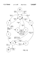
- FIG. 12 is a state diagram illustrating relationships between operational states and conditional transitions therebetween.
- FIGS. 13-18 illustrate current versus time for various paths of operation through the state diagram of FIG. 12.
- winch By serving as a shut-off device halting winch operation under certain conditions, i.e., under potentially damaging or hazardous conditions.
- winch shall refer generally to any device employing a motor to move a load.
- a winch as used herein may refer to devices for lifting loads or pulling loads and need not be limited to any particular application.
- FIG. 1 illustrates a winch system 10 in accordance with the present invention.
- Winch system 10 includes an electric motor 12 with a spool (not shown) for deploying or collecting a cable 14 attached to a load 16.
- Control terminals 12a and 12b of motor 12 receive electrical energy and, depending on the relative potential therebetween, cause motor 12 to operate in one of two rotational directions.
- a third terminal 12c of motor 12 ties to ground potential.
- a fourth terminal 12d ties to the armature of motor 12. While a variety of electric motors may be monitored under the present invention, motor 12 as illustrated herein is a series wound electric motor. By manipulating the relative potential between terminals 12a and 12b, motor 12 may be driven into one of two rotational directions.
- motor 12 may be operated in one mode to collect cable 14 by movement toward motor 12 in a direction 14a and another mode to deploy cable 14 outward in a direction 14b.
- movements of cable 14 in directions 14a and 14b are "powered" movements under the influence of motor 12.
- Motor 12 receives electrical energy from a battery 20. To accomplish selected control over motor 12, however, electrical energy from battery 20 is routed through a solenoid pack 22. As may be appreciated, solenoid pack 22 may selectably provide no energy to motor 12, energy for powered operation in direction 14a, or energy for powered operation in direction 14b. Use of a solenoid pack 22 for this purpose is known in the art. Thus, terminal 20b of battery 20 is applied to solenoid pack 22, and solenoid pack 22 couples to the terminals 12a, 12b, and 12d of motor 12. Terminal 20a of battery 20 is tied to ground potential.
- System 10 further includes a remote control station 24, e.g., a handheld control unit or a remote operator switch.
- Remote control station 24 operates in three modes, i.e., power out, off, and power in.
- Remote control station 24 provides as output a power in signal 26 and a power out signal 28.
- the signals 26 and 28 carry a positive voltage when the associated function is to be invoked by solenoid pack 22, and otherwise carry zero potential.
- motor 12 shutdown is invoked only with respect to the power in, i.e., collection of cable 14 in the direction 14a, mode of operation. Deploying cable 14, i.e., in the direction 14b, does not generally result in an overload condition for motor 12 and need not be monitored for an overload condition. Accordingly, the power out signal 28 is applied directly to solenoid pack 22, but the power in signal 26 is routed through a current limiter 30 and appears as a qualified power in signal 26' to solenoid pack 22.
- a current sensing device 32 provides a measure of current taken from terminal 20b of battery 20 and applied to the solenoid pack 22.
- current limiter 30 allows direct application of the power out signal 28 to the solenoid pack 22, i.e., has no shutdown authority over a power out command. Under a detected shutdown condition during a power in command, however, current limiter 30 prevents application of the power in signal 26' to solenoid pack 22.
- Solenoid pack 22 is a conventional arrangement of solenoids responsive to signals of remote station 24, i.e., responsive to the power in signal 26' as provided by current limiter 30 and responsive to the power out signal 28 as provided directly by remote control station 24.
- remote control station 24 generates the power in signal 26 and power out signal 28 to control solenoid pack 22, and thereby dictates normal operation of motor 12.
- Current limiter 30 intervenes, however, when necessary to shutdown operation of motor 12 during collection of cable 14 in the direction 14a as described more fully hereafter.
- FIGS. 2A and 2B illustrate by schematic diagram the current limiter 30 of FIG. 1. Details of implementation and operation of the current limiter 30 will be apparent to those skilled in the art. Several features illustrated in FIGS. 2A and 2B will be discussed more fully as follows.
- Small signal PNP transistor 50 provides a power management function by switching a positive 5 volt supply 52 employed by the hall effects transducer 32 and other circuit elements not utilized when the winch is not operating.
- the primary controlling element in current limiter 30 is a micro-controller 54.
- micro-controller 54 is an eight bit micro-controller manufactured by MicroChip, Inc. under product No. PIC16C71.
- Micro-controller 54 is a high performance, low cost CMOS fully static EPROM microcontroller with on-chip analog-to-digital conversion.
- Micro-controller 54 has four analog-to-digital (A/D) inputs.
- the A/D convertor of micro-controller 54 translates analog input voltage between zero and Vref to an eight bit digital value (zero to 255 decimal).
- Analog input 54a measures a threshold adjustment potentiometer 57 voltage to establish an overcurrent condition.
- Analog input 54b measures battery voltage as taken from voltage supply 56.
- Analog input 54c measures the output of the hall effects transducer 32.
- Analog input 54d provides a voltage reference (Vref) input. The output of the hall effects transducer 32 is measured during every cycle of the maintain control loop, described more fully hereafter.
- the battery voltage is monitored at analog input 54b during every cycle of the maintain control loop.
- resisters 58 and 60 provide voltage division to scale the potential of voltage supply 56.
- the voltage threshold taken from potentiometer 57 is the primary input determining a point at which a current overload condition begins.
- analog input 54a is calibrated by manipulation of potentiometer 57.
- the voltage source for the potentiometer 57 corresponds to the precise voltage reference applied to analog input 54d of micro-controller 54. This coordinates the threshold trip point with a precise voltage supply, and thereby provides a more accurate and constant trip point.
- transistors 68 and 70 detect the state of the power in signal 26 and power out signal 28, respectively.
- current limiter 30 merely detects the present state of power out signal 28, but dictates further application of the power in signal 26, presented as the signal 26', to the solenoid pack 22. More particularly, the power in signal 26 is applied via a relay 72 to solenoid pack 22. Power in signal 26 connects to the common terminal 72a of relay 72. Relay 72 selectively couples terminal 72a to terminal 72b. Terminal 72b, therefore, delivers the qualified power in signal 26' to the solenoid pack 22.
- current limiter 30 selectively delivers the power in signal 26 to the solenoid pack 22, i.e., may shutdown motor 12 when collecting cable 14 against the load 16. Furthermore, current limiter 30 senses the state of both power in signal 26 and power out signal 28, and dictates whether the power in signal 26 is applied to the solenoid pack 22 as a function of a present winch system 10 state of operation.
- Programming micro-controller 54 is by state machine design. As illustrated herein, the state machine includes states 0 through 7, with an additional "sleep" mode state invoked as a power conservation measure. Furthermore, micro-processor 54 employs a state counter and fixed execution time control loop to measure the duration of each state, and thereby provide an additional transition condition, e.g., state time-out, for certain states as described more fully hereafter.
- Micro-controller 54 further includes a diagnostics interface 55, i.e., a serial port, for monitoring activity of micro-controller 54 during programming and testing development.
- Interface 55 would not, however, necessarily be employed in a commercial embodiment of current limiter 30.
- interaction with micro-controller 54 during development by way of interface 55 should be limited so as not to interfere with the normal processing and control loops implemented under direction of micro-controller 54.
- FIG. 3 illustrates programming of micro-controller 54 including an initialization sequence 80 and a main control loop 82.
- the initialization sequence begins in block 84 where micro-controller 54 initializes the analog-to-digital components and input and output (I/O) resources.
- Micro-controller 54 employs a variable STATE to drive transition from one state to the next.
- a switch control structure references variable STATE to select one of a collection of procedures, each corresponding to a state of operation.
- micro-controller 54 initializes the variable STATE to a value zero, state zero being a default state of operation.
- micro-controller 54 resets a state counter register. The state counter register represents the duration of each state of operation.
- the timer interrupt of micro-controller 54 is set for a one millisecond interval.
- micro-controller 54 executes conversions on all analog-to-digital channels.
- Micro-controller 54 calculates in block 94 the battery voltage and threshold adjustment. More particularly, micro-controller 54 compensates for battery voltage variation to maintain appropriate current magnitude thresholds corresponding to a given pulling force reference, i.e., as the battery 20 voltage decreases the current trip level increases or as battery 20 voltage increases the current trip level decreases.
- the current thresholds employed as trip points correspond to a consistent load force reference. In this manner, the method of inferring load force as a function of current drawn by motor 12 accurately reflects load forces applied by motor 12.
- micro-controller 54 executes a selected procedure, i.e., one of the procedures illustrated in FIGS. 4-11 as described hereafter, as a function of the variable STATE. Each of these procedures can drive the state machine into a next state by assigning a new value to the variable STATE. Following block 96, therefore, micro-controller 54 detects in decision block 95 a change in the variable STATE, and returns to block 96 if the variable STATE has changed. Otherwise processing advances to block 98. Thus, upon a state change micro-controller 54 immediately executes a new state procedure in block 96, but otherwise completes one iteration of the main control loop 82.
- the state counter register is incremented to reflect one iteration of the main control loop 82.
- micro-controller 100 waits for the interrupt timer. With the interrupt timer set for one millisecond and the state counter register incremented once for every iteration of main control loop 82, the state counter register reflects a duration of each state.
- FIGS. 4-11 describe individually each of the procedures available for execution in block 96 as a function of the current value of the variable STATE.
- a simple switch or case control structure referencing the variable STATE drives micro-controller 54 into one of the procedures illustrated in FIGS. 4-11.
- Each of states 0-7 may be associated generally with a given mode of operation for current limiter 30 as follows.
- State 0 is an off or idle state pending user activation of remote station 24 into either the power in mode or power out mode.
- State 1 corresponds to an initial interval of operation referred to herein as an inrush interval wherein motor 12 draws, even under normal operation, an unusually large magnitude current (I 2 as described hereafter) during start-up.
- State 2 corresponds to an error condition wherein motor 12 draws current beyond that expected during the inrush interval.
- State 3 is a normal run state.
- State 4 corresponds to an overcurrent condition relative to a relatively smaller magnitude current (I 1 as described hereafter) threshold, i.e., when motor 12 draws current in excess of a normal operation current threshold.
- State 5 corresponds to a condition which is latched by an excess current condition.
- State 6 is an initial reset state.
- State 7 is a reset state.
- FIG. 4 illustrates programming of micro-controller 54 when in state 0.
- State 0 corresponds to the following conditions: power in signal 26 off, power out signal 28 off, relay 72 enabled, and no overcurrent condition detected.
- state 0 time-out interval corresponds to a time from the last power out or power in command to initiation of sleep mode.
- a suggested state 0 time-out interval is one minute.
- state 0 procedure begins in decision block 120 where the power in signal 26 is evaluated. If the power in signal 26 is on, then processing advances to block 122 where the variable STATE is assigned the value 1 and the state counter is reset to 0. Processing then terminates following execution of block 122.
- micro-controller 54 determines whether a sleep mode is required, i.e., checks a state 0 time-out interval. If no sleep mode is required, processing terminates from the NO branch of decision block 124. If, however, a sleep mode is indicated in decision block 124, then processing advances to block 126 where micro-controller 54 turns off relay 72, and also turns off transistor 50 to shutdown the 5 volt supply. Continuing to block 128, micro-processor 54 sets the interrupt for transition on a power in or power out condition.
- micro-controller 54 determines in decision block 130 whether a power in on condition exists. If a power in on condition exists, processing branches through block 132 where the variable STATE is assigned the value 1 and the state counter is reset to 0. Otherwise, processing branches from decision block 130 to decision block 134 where micro-controller 54 determines whether a power out on condition exists. If a power out on condition exists, then processing branches through block 136 where the variable STATE is assigned the value 7 and the state counter is reset to 0. Following execution of each of blocks 132 and 136, processing terminates. If no power out on condition is detected in decision block 134, then processing branches from decision block 134 back to block 126. Thus, current limiter 30 remains in a sleep mode until the next power in on condition or the next power out on condition arises.
- state 0 maintains the sleep mode until a power in on signal 26, or power out on signal 28 condition occurs. If power in on condition occurs, transition to state 1 next occurs, or until a power out on condition is detected, in which case transition to state 7 occurs.
- FIG. 5 illustrates programming of micro-controller 54 when in state 1.
- State 1 corresponds to the following conditions: power in signal 26 initially on (inrush period), power out signal 28 off, relay 72 enabled, and maximum current 12 is not exceeded.
- Processing begins in decision block 150 where the power in signal 26 is interrogated. If the power in signal 26 is on, then processing advances to decision block 152 where micro-controller 54 determines whether a maximum current 12 magnitude has been exceeded. If the maximum current 12 magnitude has been exceeded, then processing branches to block 154 where the variable STATE receives the value 2 and the state counter is reset to 0.
- micro-controller 54 determines whether an initial inrush current state 1 time-out interval is complete.
- the state 1 time-out interval corresponds to the inrush interval for motor 12, e.g., 100 milliseconds. If the inrush current time-out interval is not complete, then processing terminates. If, however, the inrush current time-out interval is complete, then processing advances to block 158 where micro-controller 54 assigns to the variable STATE the value 3 and resets the state counter.
- FIG. 6 illustrates programing of micro-controller 54 when in state 2.
- State 2 corresponds to the following conditions: power in signal 26 on, power out signal 28 off, relay 72 disabled, and maximum current 12 exceeded.
- micro-controller 54 turns off the relay 72 and advances to decision block 172 where the power in signal 26 is interrogated. If the power in signal 26 is on, then processing terminates. If, however, the power in signal 26 is not on then processing branches through block 174 where the variable STATE receives a value 5 and the state counter is reset to 0.
- FIG. 7 illustrates operation of micro-controller 54 when in state 3.
- State 3 corresponds to the following conditions: power in signal 26 on (inrush period over), power out signal 28 off, relay 72 enabled, and no overcurrent condition.
- micro-controller 54 determines whether the power in signal 26 is on. If power in signal 26 is on, then processing advances to decision block 182 where micro-controller 54 determines whether the current I 1 limit is exceeded. If the current I 1 limit is exceeded, then processing branches through block 184 where the variable STATE receives a value 4 and the state counter is reset to 0. If the current I 1 limit is not exceeded, then processing terminates from decision block 182.
- micro-controller 54 assigns in block 186 the value 0 to the variable STATE and resets the state counter.
- FIG. 8 illustrates operation of micro-controller 54 during state 4.
- State 4 corresponds to the following conditions: power in signal 26 on (inrush period over), power out signal 28 off, relay 72 enabled, and overcurrent condition exceeded.
- micro-controller 54 interrogates the power in signal 26. If power in signal 26 is on, then processing advances to block 192 where micro-controller 54 determines whether the current I 1 limit has been exceeded. If the current I 1 limit has not been exceeded, then processing advances to block 194 where micro-controller 54 assigns to the variable STATE the value 3 and resets the state counter. If the current I 1 limit has been exceeded, then processing advances from block 192 to block 196 where micro-controller 54 determines whether a state 4 time-out interval is complete.
- the state 4 time-out interval represents the maximum time allowed for an overcurrent condition after the inrush interval, i.e., a maximum time for which current limiter 30 allows current flow in excess of the current I 1 limit. A 50 millisecond period for the state 4 time-out interval is suggested. If the state 4 time-out interval is complete, then processing branches through block 198 where micro-controller 54 assigns to the variable STATE the value 5 and resets the state counter to 0. If the state 4 time-out interval is not complete, then processing terminates from decision block 196. Returning to block 190, if the power in signal 26 is not on, then processing branches through block 200 where micro-controller 54 assigns to the variable STATE the value 0 and resets the state counter to 0.
- FIG. 9 illustrates operation of micro-controller 54 during state 5.
- State 5 corresponds to the following conditions: power in signal 26 either on or off, power out signal 28 off, relay 72 disabled, and overcurrent condition was exceeded.
- Micro-controller 54 turns off relay 72 in block 210 and advances to decision block 212 where the state of power out signal 28 is detected. If the power out signal 28 is on, then processing branches through block 214 where the variable STATE receives a value 6 and the state counter is reset to 0. If, however, the power out signal 28 is not on, then processing branches from block 212 to decision block 216 where micro-controller 54 determines whether a state 5 time-out interval is complete.
- the state 5 time-out interval is the time allotted from the last power out command or power in command before current limiter 30 enters the sleep mode. A 60 second state 5 time-out interval is suggested. If the state 5 time-out interval is not complete, then processing terminates. Otherwise, processing advances from decision block 216 to block 218, i.e., goes into a sleep mode, where micro-controller 54 turns off relay 72 and turns off transistor 50 to shutdown the 5 volt supply for current limiter 30. Continuing to block 220, micro-controller 54 sets an interrupt for transition on the power in signal 26 or power out signal 28 condition.
- micro-controller 54 determines whether power in signal 26 is on. If the power in signal is not on, then processing advances to decision block 224 where the power out signal 28 is interrogated. If either of the power in signal 26 or the power out signal 28 is on, then processing advances from corresponding blocks 222 and 224 to block 226 where the variable STATE receives a value 6 and the state counter is reset. If, however, neither the power in signal 26 nor the power out signal 28 is on, then processing returns from decision block 224 to block 218 to continue the sleep mode of current limiter 30.
- FIG. 10 illustrates operation of micro-controller 54 during state 6.
- State 6 corresponds to the following conditions: power in signal 26 off, power out signal 28 on, and relay 72 disabled.
- decision block 240 micro-controller 54 interrogates the status of the power out signal 28. If on, processing branches to decision block 242 where micro-controller 54 determines whether a state 6 time-out interval is complete. The state 6 time-out interval is the minimum time that the power out command must be on to allow reset from a previous overcurrent condition. A suggested state 6 time-out interval is 500 milliseconds. If the state 6 time-out is complete, then processing branches through block 244 where the variable STATE receives a value 7 and the state counter is reset to 0. If, however, the power out signal 28 is not on, then processing branches through block 246 where the variable STATE receives the value 5 and the state counter is reset to 0.
- FIG. 11 illustrates operation during state 7.
- State 7 corresponds to the following conditions: power in signal 26 off, power out signal 28 on, relay 72 disabled, and overcurrent condition reset (exits to state 0).
- decision block 250 if the power out signal 28 is not on, then processing terminates. Otherwise, processing branches to decision block 252 where micro-controller 54 determines whether the state 7 time-out interval is complete.
- the state 7 time-out interval represents the minimum time that the power out signal 28 must be off before returning to state 0.
- a suggested state 7 time-out interval is 75 milliseconds. If the state 7 time-out interval is not complete, then processing terminates.
- FIG. 12 illustrates by state diagram transitions among the states 0-7.
- the default state is state 0 and transition out of state 0 into one of states 1 or state 7 occurs upon assertion of the power in signal 26 or power out signal 28, respectively. Transition back to state 0 from states 1 and 7 occurs upon termination of the power in signal 26 or power out signal 28. State 7 may continue indefinitely, terminating with return to state 0 upon the condition of power out signal 28 being turned off.
- State 1 may return directly to state 0 only if the power in signal 26 is turned off during the initial inrush interval. If the inrush interval is complete during state 1, then upon the corresponding inrush time-out condition transition to state 3 occurs. This corresponds to normal operation wherein a relatively high current flow is allowed during an initial inrush interval.
- transition from state 1 to state 2 occurs.
- processing in state 2 shuts down motor 12, i.e., turns off relay 72 and remains in state 2 until the power in signal 26 has been terminated and transition from state 2 to state 5 occurs. Transition from state 5 to state 6 occurs upon activation of the power out signal 28.
- transition back to state 5 may occur if the power out signal 28 is turned off, but otherwise transition to state 7 will occur upon a power out signal 28 on condition time-out interval.
- the operator must turn off the power out signal 28 to return to state 0, otherwise operation in state 7 generally represents powered deployment of cable 14 from motor 12 in direction 14b.
- transition from state 1 through states 2, 5 and 6 represents an overcurrent error condition resulting in a shutdown of the motor 12 when a maximum current I 1 limit has been exceeded during an initial inrush interval.
- transition from state 1 to state 3 denotes normal operation when an initial inrush interval has been completed after which a relatively lower current I 1 limit is employed during a power in operation of motor 12.
- State 3 may return any time directly to state 0 upon termination of the power in signal 26.
- Transition from state 3 to state 4 occurs, however, any time the relatively lower current I 1 limit is exceeded.
- the current I 1 limit may be exceeded for a brief state 4 time-out interval, but upon completion of such state 4 time-out interval, transition to state 5 occurs, i.e., processing under abnormal conditions detected.
- Transition from state 4 back to state 0 occurs, however, when the power in signal 26 is deactivated prior to the state 4 time-out interval. Transition from state 4 back to state 3 will occur any time during the state 4 time-out interval that the current falls below the current I 1 limit.
- FIGS. 13-18 illustrate operation of winch system 10 by plotting current drawn by motor 12 through intervals of time, including indication of states of operation as described herein above.
- the vertical axis represents a percentage of a selected current threshold.
- the vertical axis of FIG. 13 represents the maximum current 12 magnitude and the vertical axis in FIGS. 14-18 represent the current I 1 limit.
- the horizontal axis in FIGS. 13-18 represents both time and sequential states of operation.
- FIG. 13 represents an example of overcurrent during the initial inrush interval.
- signal 300 represents current drawn by motor 12, in particular the percentage of current drawn with respect to the current 12 magnitude.
- Signal 302 represents the condition of the power in signal 26, essentially a bistate signal, and signal 304 represents the condition of power out signal 28, also a bistate signal. Illustration of signals 300, 302 and 304 is provided to depict generally the relative timing, and not necessarily to scale or accurate signal shapes.
- Current limiter 30 is initially in state 0. At time t 0 the remote control station 24 moves to the power in position and the current limiter 30 enters state 1. The inrush current 300 to motor 12 rises quickly in state 1 to a value greater than the maximum current 12 magnitude.
- current limiter 30 enters state 2 and disconnects power from the solenoid pack 22 to motor 12 at time t 1 , turning off motor 12 and causing signal 300 to return to zero.
- remote control station 24 returns to its center off position, equivalent to a power in signal 26 off, and current limiter 30 enters state 5.
- the remote control station 24 moves to the power out position and current limiter 30 enters state 6.
- current limiter 30 enters state 7.
- remote control station 24 returns to its center off position, equivalent to power out signal 28 off, and current limiter 30 returns to state 0.
- FIG. 14 illustrated normal operation, including entry into sleep mode.
- current limiter 30 turns on the +5 V supply to non-critical circuit elements, turns on output relay 72, and enters state 1.
- the inrush current 300 to motor 12 rises quickly, but does not exceed the maximum current 12 limit during state 1.
- Current limiter 30 then enters state 3 at time t 1 , i.e., following the state 1 time-out interval.
- remote control station 24 returns to its center off position, equivalent to power in signal 26 off, and current limiter 30 returns to state 0.
- current limiter 30 turns off the +5 V supply to non-critical circuits, turns off output relay 72, and goes into sleep mode.
- FIG. 15 illustrates an overcurrent condition relative to the current I 1 limit, i.e., an overcurrent condition following the initial inrush interval.
- current limiter 30 is initially in state 0.
- the remote control station 24 moves to the power in position and current limiter 30 enters state 1.
- the inrush current 300 to motor 12 rises quickly in state 1, but does not exceed the maximum current 12 magnitude.
- Current limiter 30 then enters state 3 after the state 1 time-out interval.
- the current 300 drawn by motor 12 exceeds the current I 1 magnitude and enters state 4.
- FIG. 16 illustrates an overcurrent condition relative to the current I 1 limit with power in signal 26 being discontinued before the state 4 time-out interval has elapsed.
- current limiter 30 is initially in state 0.
- remote control station 24 moves to the power in position and current limiter 30 enters state 1.
- the inrush current 300 to motor 12 rises quickly in state 1, but does not exceed the maximum current 12 magnitude.
- Current limiter 30 then enters state 3 after expiration of the state 1 time-out interval.
- the current drawn by motor 12 exceeds the current I 1 magnitude and current limiter 30 enters state 4.
- remote control switch 24 moves to the off position before the state 4 time-out interval is complete, and current limiter 30 returns directly to state 0.
- FIG. 17 illustrates an overcurrent condition relative to current I 1 limit including a failed reset time-out in state 6.
- current limiter 30 is initially in state 0.
- remote control station 24 moves to the power in position and current limiter 30 enters state 1.
- the inrush current 300 to motor 12 rises quickly in state 1, but does not exceed the maximum current I 2 magnitude.
- Current limiter 30 then enters state 3 after the state 1 time-out interval.
- the current signal 300 exceeds the current I 1 magnitude and current limiter 30 enters state 4.
- current signal 300 has exceeded the current I 1 limit for a maximum period of time, and current limiter 30 disconnects power from the solenoid pack 22, turning off motor 12, i.e., driving signal 300 to zero, and current limiter 30 enters state 5.
- remote control station 24 returns to its center off position, equivalent to power in signal 26 off.
- remote control station 24 moves to the power out position and current limiter 30 enters state 6.
- remote control station 24 returns to its center off position before the state 6 time-out interval and current limiter 30 returns to state 5 without resetting the overcurrent condition.
- FIG. 18 illustrates a momentary overcurrent condition relative to the current I 1 limit.
- remote control station 24 moves to the power in position and current limiter 30 turns on the +5 V supply to non-critical circuit elements, turns on output relay 72, and enters state 1.
- the inrush current 300 to the motor rises quickly but does not exceed the current I 2 magnitude during state 1.
- Current limiter 30 then enters state 3 at time t 1 after the state 1 time-out interval.
- the current signal 300 exceeds the current I 1 limit and state 4 begins.
- the current signal 300 drops to a level less than the current I 1 limit, before the state 4 time-out interval, and current limiter 30 returns to state 3.
- remote control station 24 returns to its center off position, equivalent to power in signal 26 off, and current limiter 30 returns to state 0.
- winch system 10 may be enhanced by incorporating additional inputs to current limiter 30.
- motor 12 includes a layer output 400 representing the number of layers of cable 14 residing on the spool of motor 12. Implementation of such sensing devices as represented by layer output 400 in FIG. 1 will be apparent to those skilled in the art. Layer output 400 is applied to the current limiter 30 as an additional operational input parameter for enhanced use of winch system 10.
- a given magnitude of current drawn by motor 12 actually represents a range of potential pulling force provided by motor 12 relative to cable 14.
- a fixed magnitude pulling force by motor 12 corresponds to a range of potential current magnitudes, depending on the number of layers on the motor 12 spool, i.e., as a function of layer output 400. For example, to achieve a given pulling force with a maximum number of layers, a given magnitude current is drawn by motor 12, but a lesser magnitude of current is drawn by motor 12 when the spool thereof has fewer layers of cable 14 thereon.
- current limiter 30 is employed to shutdown motor 12 operation when a given magnitude current is detected and this actually corresponds to a range of pulling force.
- Current limiter 30 may be modified, therefore, to provide as a shut-off condition a given magnitude pulling force.
- threshold calculations performed in block 94 of FIG. 3 account for the layer output 400 and offset such current threshold trip points as a function of the lever arm advantage provided by the spool of motor 12, i.e., as a function of the layer output 400.
- the current threshold trip points are reduced as the layer output 400 indicates fewer layers of cable 14 on the spool of motor 12.
- Such adjustment in threshold trip points as a function of layer output 400 provides as a shut-off condition a constant magnitude pulling force.
- current limiter 30 may be modified to shutdown motor 12 operation when the selected magnitude pulling force is exceeded.
- the current limiter allow a relatively high magnitude of current during an initial inrush interval. During such initial inrush interval, if the relatively high magnitude threshold is exceeded, then processing advances to handle the abnormal operating condition. Following the initial inrush interval, current limiter 30 employs a relatively lower current threshold level to detect excess load conditions on the motor. In this manner, the motor and associated support structures are protected against an overload condition throughout operation, i.e., commencing with the inrush interval and continuing throughout operation of the motor. Furthermore, the current limiter may take into account variation in battery voltage to establish a consistent current threshold trip point, and thereby consistently shutdown winch operation relative to a given pulling force, or range of pulling force.
- the current limiter can take into account a variable lever arm resulting from variation in the number of layers of wire rope on the motor spool to establish as a shutdown condition, when desired, a relatively fixed magnitude pulling force, as opposed to a range of pulling force as associated with a constant magnitude current threshold.
Abstract
Description
Claims (22)
Priority Applications (1)
| Application Number | Priority Date | Filing Date | Title |
|---|---|---|---|
| US08/257,654 US5648887A (en) | 1994-06-09 | 1994-06-09 | Electric current limiting device for winch responsive to multiple device states |
Applications Claiming Priority (1)
| Application Number | Priority Date | Filing Date | Title |
|---|---|---|---|
| US08/257,654 US5648887A (en) | 1994-06-09 | 1994-06-09 | Electric current limiting device for winch responsive to multiple device states |
Publications (1)
| Publication Number | Publication Date |
|---|---|
| US5648887A true US5648887A (en) | 1997-07-15 |
Family
ID=22977187
Family Applications (1)
| Application Number | Title | Priority Date | Filing Date |
|---|---|---|---|
| US08/257,654 Expired - Fee Related US5648887A (en) | 1994-06-09 | 1994-06-09 | Electric current limiting device for winch responsive to multiple device states |
Country Status (1)
| Country | Link |
|---|---|
| US (1) | US5648887A (en) |
Cited By (35)
| Publication number | Priority date | Publication date | Assignee | Title |
|---|---|---|---|---|
| US5847908A (en) * | 1997-12-17 | 1998-12-08 | Ingersoll-Rand Company | Machine having current loss shutdown circuit with low resistance relay |
| US5994650A (en) * | 1996-03-28 | 1999-11-30 | Bt Industries Ab | Safety system for lift trucks |
| EP0969579A2 (en) * | 1998-06-30 | 2000-01-05 | Siemens Aktiengesellschaft | Electronic overcurrent tripping relay and method of operating same |
| US6046893A (en) * | 1998-06-06 | 2000-04-04 | Warn Industries, Inc. | Programmable electronic current limiter |
| WO2001024338A1 (en) * | 1999-09-30 | 2001-04-05 | Siemens Aktiengesellschaft | Method for operating a circuit-breaker |
| US6268708B1 (en) * | 1998-02-24 | 2001-07-31 | Nsk Ltd. | Control apparatus for electric power steering system |
| US20020191361A1 (en) * | 2001-06-19 | 2002-12-19 | Schneider Electric Industries S.A. | Electronic trip device comprising a capacitor for supply of a trip coil |
| US20040263100A1 (en) * | 2003-06-24 | 2004-12-30 | Oliver Heravi | Winch controller |
| US20050211966A1 (en) * | 2004-03-12 | 2005-09-29 | Oliver Heravi | Low voltage interrupter for electric winch |
| US20080055807A1 (en) * | 2004-09-28 | 2008-03-06 | Freescale Semiconductor Inc. | Power Switching Apparatus With Overload Protection |
| WO2008025237A1 (en) * | 2006-08-23 | 2008-03-06 | Mile Marker (Shenzhen) Limited | Motor control device and its control method |
| WO2008025235A1 (en) * | 2006-08-23 | 2008-03-06 | Mile Marker (Shenzhen) Limited | Motor control device and its control method |
| US20080084172A1 (en) * | 2006-10-10 | 2008-04-10 | Square D Company | DC motor mechanical shock protection system |
| WO2008043238A1 (en) * | 2006-09-27 | 2008-04-17 | Mile Marker (Shenzhen) Limited | An h-bridge control system and its control method |
| US20080116430A1 (en) * | 2006-11-20 | 2008-05-22 | Warn Industries, Inc. | Winch Assembly Including Clutch Mechanism |
| US20080116431A1 (en) * | 2006-11-20 | 2008-05-22 | Warn Industries, Inc. | Winch Assembly Including Clutch Mechanism |
| US20080246011A1 (en) * | 2007-04-05 | 2008-10-09 | Warn Industries, Inc. | Portable Pulling Tool |
| US20090284877A1 (en) * | 2008-05-15 | 2009-11-19 | Warn Industries, Inc. | Integrated Overload and Low Voltage Interrupt Module |
| US8164293B2 (en) | 2009-09-08 | 2012-04-24 | Hoffman Enclosures, Inc. | Method of controlling a motor |
| US8183810B2 (en) | 2009-09-08 | 2012-05-22 | Hoffman Enclosures, Inc. | Method of operating a motor |
| US20120188673A1 (en) * | 2011-01-20 | 2012-07-26 | Triune Ip Llc | Electrical line status monitoring system |
| US8297369B2 (en) | 2009-09-08 | 2012-10-30 | Sta-Rite Industries, Llc | Fire-extinguishing system with servo motor-driven foam pump |
| CN102810850A (en) * | 2011-05-31 | 2012-12-05 | 比亚迪股份有限公司 | Method for protecting overload running of electric motor |
| US20140368956A1 (en) * | 2013-03-13 | 2014-12-18 | Andre Pierre Perra | Apparatus, System, and/or Method for Intelligent Motor Protection and/or Control |
| US8958956B1 (en) | 2014-03-10 | 2015-02-17 | Jimmie Doyle Felps | Battery supervisor system having smart winch control |
| USD807733S1 (en) | 2016-10-28 | 2018-01-16 | Warn Industries, Inc. | Lighted fairlead |
| USD807732S1 (en) | 2016-10-28 | 2018-01-16 | Warn Industries, Inc. | Fairlead |
| USD807731S1 (en) | 2016-10-28 | 2018-01-16 | Warn Industries, Inc. | Fairlead |
| USD811684S1 (en) | 2016-10-28 | 2018-02-27 | Warn Industries, Inc. | Control pack of a winch |
| USD811685S1 (en) | 2016-10-28 | 2018-02-27 | Warn Industries, Inc. | Clutch lever of a winch |
| US10093523B2 (en) * | 2014-10-06 | 2018-10-09 | Warn Industries, Inc. | Programmable controls for a winch |
| WO2019090324A1 (en) | 2017-11-06 | 2019-05-09 | Ramsey Winch Company | Electric winch control module with magnetic flux shield |
| US10958265B1 (en) | 2020-01-07 | 2021-03-23 | Inpower Llc | Winch motor protection circuit |
| CN113555851A (en) * | 2020-04-26 | 2021-10-26 | 浙江阜康机械有限公司 | High-precision overcurrent protector of electric capstan |
| US11225401B2 (en) * | 2018-01-19 | 2022-01-18 | Soucy International Inc. | Circuit and method for controlling electric power delivered to an electric motor |
Citations (15)
| Publication number | Priority date | Publication date | Assignee | Title |
|---|---|---|---|---|
| US3965407A (en) * | 1973-02-15 | 1976-06-22 | Bucyrus-Erie Company | Method and means for measuring the torque delivered by an electric motor |
| JPS54153248A (en) * | 1978-05-24 | 1979-12-03 | Mitsubishi Electric Corp | Current controller |
| JPS5612890A (en) * | 1979-07-06 | 1981-02-07 | Mitsubishi Electric Corp | Controlling circuit for motor |
| US4260938A (en) * | 1975-02-28 | 1981-04-07 | Lucas Industries Limited | Control circuits for electrically driven vehicles |
| US4517506A (en) * | 1980-12-27 | 1985-05-14 | Robert Bosch Gmbh | Wrench provided with an alternating current drive motor |
| US4532571A (en) * | 1982-11-12 | 1985-07-30 | Tokyo Shibaura Denki Kabushiki Kaisha | Circuit breaker |
| US4713720A (en) * | 1986-05-14 | 1987-12-15 | Litton Systems, Inc. | Fast acting solid state AC circuit breaker |
| US4854547A (en) * | 1987-08-24 | 1989-08-08 | Harnischfeger Corporation | Vehicle-mounted retrieval winch and control means therefor |
| US4873474A (en) * | 1989-04-20 | 1989-10-10 | Warn Industries, Inc. | Winch with shut-off load limiter |
| US4905117A (en) * | 1988-09-02 | 1990-02-27 | Westinghouse Electric Corp. | Circuit and method for DC content protection of parallel VSCF power systems |
| US4956590A (en) * | 1988-10-06 | 1990-09-11 | Techco Corporation | Vehicular power steering system |
| US4987358A (en) * | 1989-04-21 | 1991-01-22 | Branam Timothy R | Electronic torque switch |
| US5214359A (en) * | 1991-11-01 | 1993-05-25 | Warn Industries, Inc. | Winch with electronic current limiter |
| US5436579A (en) * | 1993-09-07 | 1995-07-25 | Advanced Micro Devices, Inc. | Input transition detection circuit for zero-power part |
| US5448442A (en) * | 1988-06-22 | 1995-09-05 | Siemens Energy & Automation, Inc. | Motor controller with instantaneous trip protection |
-
1994
- 1994-06-09 US US08/257,654 patent/US5648887A/en not_active Expired - Fee Related
Patent Citations (15)
| Publication number | Priority date | Publication date | Assignee | Title |
|---|---|---|---|---|
| US3965407A (en) * | 1973-02-15 | 1976-06-22 | Bucyrus-Erie Company | Method and means for measuring the torque delivered by an electric motor |
| US4260938A (en) * | 1975-02-28 | 1981-04-07 | Lucas Industries Limited | Control circuits for electrically driven vehicles |
| JPS54153248A (en) * | 1978-05-24 | 1979-12-03 | Mitsubishi Electric Corp | Current controller |
| JPS5612890A (en) * | 1979-07-06 | 1981-02-07 | Mitsubishi Electric Corp | Controlling circuit for motor |
| US4517506A (en) * | 1980-12-27 | 1985-05-14 | Robert Bosch Gmbh | Wrench provided with an alternating current drive motor |
| US4532571A (en) * | 1982-11-12 | 1985-07-30 | Tokyo Shibaura Denki Kabushiki Kaisha | Circuit breaker |
| US4713720A (en) * | 1986-05-14 | 1987-12-15 | Litton Systems, Inc. | Fast acting solid state AC circuit breaker |
| US4854547A (en) * | 1987-08-24 | 1989-08-08 | Harnischfeger Corporation | Vehicle-mounted retrieval winch and control means therefor |
| US5448442A (en) * | 1988-06-22 | 1995-09-05 | Siemens Energy & Automation, Inc. | Motor controller with instantaneous trip protection |
| US4905117A (en) * | 1988-09-02 | 1990-02-27 | Westinghouse Electric Corp. | Circuit and method for DC content protection of parallel VSCF power systems |
| US4956590A (en) * | 1988-10-06 | 1990-09-11 | Techco Corporation | Vehicular power steering system |
| US4873474A (en) * | 1989-04-20 | 1989-10-10 | Warn Industries, Inc. | Winch with shut-off load limiter |
| US4987358A (en) * | 1989-04-21 | 1991-01-22 | Branam Timothy R | Electronic torque switch |
| US5214359A (en) * | 1991-11-01 | 1993-05-25 | Warn Industries, Inc. | Winch with electronic current limiter |
| US5436579A (en) * | 1993-09-07 | 1995-07-25 | Advanced Micro Devices, Inc. | Input transition detection circuit for zero-power part |
Cited By (50)
| Publication number | Priority date | Publication date | Assignee | Title |
|---|---|---|---|---|
| US5994650A (en) * | 1996-03-28 | 1999-11-30 | Bt Industries Ab | Safety system for lift trucks |
| US5847908A (en) * | 1997-12-17 | 1998-12-08 | Ingersoll-Rand Company | Machine having current loss shutdown circuit with low resistance relay |
| US6268708B1 (en) * | 1998-02-24 | 2001-07-31 | Nsk Ltd. | Control apparatus for electric power steering system |
| US6046893A (en) * | 1998-06-06 | 2000-04-04 | Warn Industries, Inc. | Programmable electronic current limiter |
| EP0969579A2 (en) * | 1998-06-30 | 2000-01-05 | Siemens Aktiengesellschaft | Electronic overcurrent tripping relay and method of operating same |
| EP0969579A3 (en) * | 1998-06-30 | 2002-12-18 | Siemens Aktiengesellschaft | Electronic overcurrent tripping relay and method of operating same |
| WO2001024338A1 (en) * | 1999-09-30 | 2001-04-05 | Siemens Aktiengesellschaft | Method for operating a circuit-breaker |
| US20020191361A1 (en) * | 2001-06-19 | 2002-12-19 | Schneider Electric Industries S.A. | Electronic trip device comprising a capacitor for supply of a trip coil |
| US20040263100A1 (en) * | 2003-06-24 | 2004-12-30 | Oliver Heravi | Winch controller |
| US6864650B2 (en) | 2003-06-24 | 2005-03-08 | Warn Industries, Inc. | Winch controller |
| US20050211966A1 (en) * | 2004-03-12 | 2005-09-29 | Oliver Heravi | Low voltage interrupter for electric winch |
| US7262947B2 (en) | 2004-03-12 | 2007-08-28 | Warn Industries, Inc. | Low voltage interrupter for electric winch |
| US20080055807A1 (en) * | 2004-09-28 | 2008-03-06 | Freescale Semiconductor Inc. | Power Switching Apparatus With Overload Protection |
| US7808757B2 (en) * | 2004-09-28 | 2010-10-05 | Freescale Semiconductor, Inc. | Power switching apparatus with overload protection |
| WO2008025237A1 (en) * | 2006-08-23 | 2008-03-06 | Mile Marker (Shenzhen) Limited | Motor control device and its control method |
| WO2008025235A1 (en) * | 2006-08-23 | 2008-03-06 | Mile Marker (Shenzhen) Limited | Motor control device and its control method |
| WO2008043238A1 (en) * | 2006-09-27 | 2008-04-17 | Mile Marker (Shenzhen) Limited | An h-bridge control system and its control method |
| US20080084172A1 (en) * | 2006-10-10 | 2008-04-10 | Square D Company | DC motor mechanical shock protection system |
| US7548036B2 (en) * | 2006-10-10 | 2009-06-16 | Square D Company | DC motor mechanical shock protection system |
| US7703751B2 (en) | 2006-11-20 | 2010-04-27 | Warn Industries, Inc. | Winch assembly including clutch mechanism |
| US7588233B2 (en) | 2006-11-20 | 2009-09-15 | Warn Industries, Inc. | Winch assembly including clutch mechanism |
| US20080116431A1 (en) * | 2006-11-20 | 2008-05-22 | Warn Industries, Inc. | Winch Assembly Including Clutch Mechanism |
| US20080116430A1 (en) * | 2006-11-20 | 2008-05-22 | Warn Industries, Inc. | Winch Assembly Including Clutch Mechanism |
| US7850145B2 (en) | 2007-04-05 | 2010-12-14 | Warn Industries, Inc. | Portable pulling tool |
| US20080246011A1 (en) * | 2007-04-05 | 2008-10-09 | Warn Industries, Inc. | Portable Pulling Tool |
| US20090284877A1 (en) * | 2008-05-15 | 2009-11-19 | Warn Industries, Inc. | Integrated Overload and Low Voltage Interrupt Module |
| US8076885B2 (en) * | 2008-05-15 | 2011-12-13 | Warn Industries, Inc. | Integrated overload and low voltage interrupt module |
| US8297369B2 (en) | 2009-09-08 | 2012-10-30 | Sta-Rite Industries, Llc | Fire-extinguishing system with servo motor-driven foam pump |
| US8164293B2 (en) | 2009-09-08 | 2012-04-24 | Hoffman Enclosures, Inc. | Method of controlling a motor |
| US8183810B2 (en) | 2009-09-08 | 2012-05-22 | Hoffman Enclosures, Inc. | Method of operating a motor |
| US9906018B2 (en) * | 2011-01-20 | 2018-02-27 | Triune Systems, LLC | Electrical line status monitoring system |
| US20120188673A1 (en) * | 2011-01-20 | 2012-07-26 | Triune Ip Llc | Electrical line status monitoring system |
| CN102810850A (en) * | 2011-05-31 | 2012-12-05 | 比亚迪股份有限公司 | Method for protecting overload running of electric motor |
| CN102810850B (en) * | 2011-05-31 | 2015-08-26 | 比亚迪股份有限公司 | A kind of motor overload operation protection method |
| US20140368956A1 (en) * | 2013-03-13 | 2014-12-18 | Andre Pierre Perra | Apparatus, System, and/or Method for Intelligent Motor Protection and/or Control |
| CN105453361A (en) * | 2013-03-13 | 2016-03-30 | 富兰克林控制系统有限公司 | Apparatus, system, and/or method for intelligent motor protection and/or control |
| US8958956B1 (en) | 2014-03-10 | 2015-02-17 | Jimmie Doyle Felps | Battery supervisor system having smart winch control |
| US11104557B2 (en) | 2014-10-06 | 2021-08-31 | Warn Industries, Inc. | Programmable controls for a winch |
| US10093523B2 (en) * | 2014-10-06 | 2018-10-09 | Warn Industries, Inc. | Programmable controls for a winch |
| USD811684S1 (en) | 2016-10-28 | 2018-02-27 | Warn Industries, Inc. | Control pack of a winch |
| USD811685S1 (en) | 2016-10-28 | 2018-02-27 | Warn Industries, Inc. | Clutch lever of a winch |
| USD807731S1 (en) | 2016-10-28 | 2018-01-16 | Warn Industries, Inc. | Fairlead |
| USD807732S1 (en) | 2016-10-28 | 2018-01-16 | Warn Industries, Inc. | Fairlead |
| USD807733S1 (en) | 2016-10-28 | 2018-01-16 | Warn Industries, Inc. | Lighted fairlead |
| WO2019090324A1 (en) | 2017-11-06 | 2019-05-09 | Ramsey Winch Company | Electric winch control module with magnetic flux shield |
| US10934141B2 (en) | 2017-11-06 | 2021-03-02 | Ramsey Winch Company | Electric winch control module with magnetic flux shield |
| US11225401B2 (en) * | 2018-01-19 | 2022-01-18 | Soucy International Inc. | Circuit and method for controlling electric power delivered to an electric motor |
| US10958265B1 (en) | 2020-01-07 | 2021-03-23 | Inpower Llc | Winch motor protection circuit |
| CN113555851A (en) * | 2020-04-26 | 2021-10-26 | 浙江阜康机械有限公司 | High-precision overcurrent protector of electric capstan |
| CN113555851B (en) * | 2020-04-26 | 2023-12-08 | 浙江阜康机械有限公司 | High-precision overcurrent protector of electric winch |
Similar Documents
| Publication | Publication Date | Title |
|---|---|---|
| US5648887A (en) | Electric current limiting device for winch responsive to multiple device states | |
| US4430681A (en) | Overload protection arrangement for an electric motor, especially of a hand-held power tool | |
| EP1851842B1 (en) | Independent automatic shedding branch circuit breaker | |
| US5117325A (en) | Controllable recloser for power line | |
| EP1769316A1 (en) | Power saver controller | |
| CA1331797C (en) | Combined input/output circuit for a programmable controller | |
| CN107701782B (en) | A kind of valve positioner of the hall signal using brushless motor | |
| JP2002534943A (en) | Event analysis method for electronic devices with advanced processing capabilities | |
| CA2698290A1 (en) | Brushless dc motor with soft-starting of pwm signals | |
| US4875000A (en) | Current fault detection system and method for AC controller | |
| CN1987695B (en) | Method for the operation of a home automation device | |
| EP1589629B1 (en) | A self-supplied electronic protection device for automatic circuit-breakers | |
| CN104836484B (en) | A kind of rope drive system and its control method based on redundancy backup | |
| US9449777B2 (en) | Circuit breaker arrangement and power distribution unit | |
| US4707760A (en) | Mains protection device | |
| JP2000060172A (en) | Motor drive/stop control device | |
| KR20010080785A (en) | Overload Cutoff Device for Hoist and Crane | |
| JP2005012892A (en) | Power load coordination control system | |
| CN111817609B (en) | Soft start method and system for motor | |
| EP0275633B1 (en) | Control of multiphase ac motors | |
| JP2002525002A (en) | Control circuit for motor operated switch | |
| JP3527316B2 (en) | Excitation control device for synchronous generator | |
| CN209860580U (en) | Intelligent motor protector | |
| CN206727633U (en) | A kind of overvoltage crowbar and earth leakage protective device | |
| JP2831806B2 (en) | Motor control device |
Legal Events
| Date | Code | Title | Description |
|---|---|---|---|
| AS | Assignment |
Owner name: WARN INDUSTRIES, INC., OREGON Free format text: ASSIGNMENT OF ASSIGNORS INTEREST;ASSIGNORS:HERNDON, RICHARD S.;PAULSON, JEFFREY E.;PROEBSTEL, ROBERT C.;REEL/FRAME:007108/0325 Effective date: 19940816 |
|
| CC | Certificate of correction | ||
| AS | Assignment |
Owner name: FLEET CAPITAL CORPORATION, CALIFORNIA Free format text: SECURITY AGREEMENT;ASSIGNOR:WARN INDUSTRIES, INC.;REEL/FRAME:010628/0024 Effective date: 20000215 |
|
| FPAY | Fee payment |
Year of fee payment: 4 |
|
| AS | Assignment |
Owner name: WARN INDUSTRIES, INC., OREGON Free format text: RELEASE OF ASSIGNMENT FOR SECURITY OF PATENTS;ASSIGNOR:FLEET CAPITAL CORPORATION;REEL/FRAME:014609/0435 Effective date: 20031001 |
|
| REMI | Maintenance fee reminder mailed | ||
| LAPS | Lapse for failure to pay maintenance fees | ||
| STCH | Information on status: patent discontinuation |
Free format text: PATENT EXPIRED DUE TO NONPAYMENT OF MAINTENANCE FEES UNDER 37 CFR 1.362 |
|
| FP | Lapsed due to failure to pay maintenance fee |
Effective date: 20050715 |