US5659563A - Solid state laser with relay optics - Google Patents
Solid state laser with relay optics Download PDFInfo
- Publication number
- US5659563A US5659563A US08/331,359 US33135994A US5659563A US 5659563 A US5659563 A US 5659563A US 33135994 A US33135994 A US 33135994A US 5659563 A US5659563 A US 5659563A
- Authority
- US
- United States
- Prior art keywords
- laser
- delivery device
- location
- constant
- optical
- Prior art date
- Legal status (The legal status is an assumption and is not a legal conclusion. Google has not performed a legal analysis and makes no representation as to the accuracy of the status listed.)
- Expired - Fee Related
Links
Images


Classifications
-
- G—PHYSICS
- G02—OPTICS
- G02B—OPTICAL ELEMENTS, SYSTEMS OR APPARATUS
- G02B6/00—Light guides; Structural details of arrangements comprising light guides and other optical elements, e.g. couplings
- G02B6/24—Coupling light guides
- G02B6/42—Coupling light guides with opto-electronic elements
- G02B6/4296—Coupling light guides with opto-electronic elements coupling with sources of high radiant energy, e.g. high power lasers, high temperature light sources
-
- H—ELECTRICITY
- H01—ELECTRIC ELEMENTS
- H01S—DEVICES USING THE PROCESS OF LIGHT AMPLIFICATION BY STIMULATED EMISSION OF RADIATION [LASER] TO AMPLIFY OR GENERATE LIGHT; DEVICES USING STIMULATED EMISSION OF ELECTROMAGNETIC RADIATION IN WAVE RANGES OTHER THAN OPTICAL
- H01S3/00—Lasers, i.e. devices using stimulated emission of electromagnetic radiation in the infrared, visible or ultraviolet wave range
- H01S3/02—Constructional details
- H01S3/04—Arrangements for thermal management
- H01S3/042—Arrangements for thermal management for solid state lasers
-
- H—ELECTRICITY
- H01—ELECTRIC ELEMENTS
- H01S—DEVICES USING THE PROCESS OF LIGHT AMPLIFICATION BY STIMULATED EMISSION OF RADIATION [LASER] TO AMPLIFY OR GENERATE LIGHT; DEVICES USING STIMULATED EMISSION OF ELECTROMAGNETIC RADIATION IN WAVE RANGES OTHER THAN OPTICAL
- H01S3/00—Lasers, i.e. devices using stimulated emission of electromagnetic radiation in the infrared, visible or ultraviolet wave range
- H01S3/09—Processes or apparatus for excitation, e.g. pumping
- H01S3/091—Processes or apparatus for excitation, e.g. pumping using optical pumping
- H01S3/0915—Processes or apparatus for excitation, e.g. pumping using optical pumping by incoherent light
- H01S3/092—Processes or apparatus for excitation, e.g. pumping using optical pumping by incoherent light of flash lamp
-
- H—ELECTRICITY
- H01—ELECTRIC ELEMENTS
- H01S—DEVICES USING THE PROCESS OF LIGHT AMPLIFICATION BY STIMULATED EMISSION OF RADIATION [LASER] TO AMPLIFY OR GENERATE LIGHT; DEVICES USING STIMULATED EMISSION OF ELECTROMAGNETIC RADIATION IN WAVE RANGES OTHER THAN OPTICAL
- H01S3/00—Lasers, i.e. devices using stimulated emission of electromagnetic radiation in the infrared, visible or ultraviolet wave range
- H01S3/23—Arrangements of two or more lasers not provided for in groups H01S3/02 - H01S3/22, e.g. tandem arrangements of separate active media
- H01S3/2383—Parallel arrangements
-
- H—ELECTRICITY
- H01—ELECTRIC ELEMENTS
- H01S—DEVICES USING THE PROCESS OF LIGHT AMPLIFICATION BY STIMULATED EMISSION OF RADIATION [LASER] TO AMPLIFY OR GENERATE LIGHT; DEVICES USING STIMULATED EMISSION OF ELECTROMAGNETIC RADIATION IN WAVE RANGES OTHER THAN OPTICAL
- H01S3/00—Lasers, i.e. devices using stimulated emission of electromagnetic radiation in the infrared, visible or ultraviolet wave range
- H01S3/005—Optical devices external to the laser cavity, specially adapted for lasers, e.g. for homogenisation of the beam or for manipulating laser pulses, e.g. pulse shaping
- H01S3/0071—Beam steering, e.g. whereby a mirror outside the cavity is present to change the beam direction
-
- H—ELECTRICITY
- H01—ELECTRIC ELEMENTS
- H01S—DEVICES USING THE PROCESS OF LIGHT AMPLIFICATION BY STIMULATED EMISSION OF RADIATION [LASER] TO AMPLIFY OR GENERATE LIGHT; DEVICES USING STIMULATED EMISSION OF ELECTROMAGNETIC RADIATION IN WAVE RANGES OTHER THAN OPTICAL
- H01S3/00—Lasers, i.e. devices using stimulated emission of electromagnetic radiation in the infrared, visible or ultraviolet wave range
- H01S3/02—Constructional details
- H01S3/025—Constructional details of solid state lasers, e.g. housings or mountings
-
- H—ELECTRICITY
- H01—ELECTRIC ELEMENTS
- H01S—DEVICES USING THE PROCESS OF LIGHT AMPLIFICATION BY STIMULATED EMISSION OF RADIATION [LASER] TO AMPLIFY OR GENERATE LIGHT; DEVICES USING STIMULATED EMISSION OF ELECTROMAGNETIC RADIATION IN WAVE RANGES OTHER THAN OPTICAL
- H01S3/00—Lasers, i.e. devices using stimulated emission of electromagnetic radiation in the infrared, visible or ultraviolet wave range
- H01S3/02—Constructional details
- H01S3/04—Arrangements for thermal management
- H01S3/0407—Liquid cooling, e.g. by water
-
- H—ELECTRICITY
- H01—ELECTRIC ELEMENTS
- H01S—DEVICES USING THE PROCESS OF LIGHT AMPLIFICATION BY STIMULATED EMISSION OF RADIATION [LASER] TO AMPLIFY OR GENERATE LIGHT; DEVICES USING STIMULATED EMISSION OF ELECTROMAGNETIC RADIATION IN WAVE RANGES OTHER THAN OPTICAL
- H01S3/00—Lasers, i.e. devices using stimulated emission of electromagnetic radiation in the infrared, visible or ultraviolet wave range
- H01S3/09—Processes or apparatus for excitation, e.g. pumping
- H01S3/091—Processes or apparatus for excitation, e.g. pumping using optical pumping
- H01S3/0915—Processes or apparatus for excitation, e.g. pumping using optical pumping by incoherent light
- H01S3/092—Processes or apparatus for excitation, e.g. pumping using optical pumping by incoherent light of flash lamp
- H01S3/093—Processes or apparatus for excitation, e.g. pumping using optical pumping by incoherent light of flash lamp focusing or directing the excitation energy into the active medium
- H01S3/0931—Imaging pump cavity, e.g. elliptical
-
- H—ELECTRICITY
- H01—ELECTRIC ELEMENTS
- H01S—DEVICES USING THE PROCESS OF LIGHT AMPLIFICATION BY STIMULATED EMISSION OF RADIATION [LASER] TO AMPLIFY OR GENERATE LIGHT; DEVICES USING STIMULATED EMISSION OF ELECTROMAGNETIC RADIATION IN WAVE RANGES OTHER THAN OPTICAL
- H01S3/00—Lasers, i.e. devices using stimulated emission of electromagnetic radiation in the infrared, visible or ultraviolet wave range
- H01S3/10—Controlling the intensity, frequency, phase, polarisation or direction of the emitted radiation, e.g. switching, gating, modulating or demodulating
- H01S3/10038—Amplitude control
- H01S3/10046—Pulse repetition rate control
-
- H—ELECTRICITY
- H01—ELECTRIC ELEMENTS
- H01S—DEVICES USING THE PROCESS OF LIGHT AMPLIFICATION BY STIMULATED EMISSION OF RADIATION [LASER] TO AMPLIFY OR GENERATE LIGHT; DEVICES USING STIMULATED EMISSION OF ELECTROMAGNETIC RADIATION IN WAVE RANGES OTHER THAN OPTICAL
- H01S3/00—Lasers, i.e. devices using stimulated emission of electromagnetic radiation in the infrared, visible or ultraviolet wave range
- H01S3/10—Controlling the intensity, frequency, phase, polarisation or direction of the emitted radiation, e.g. switching, gating, modulating or demodulating
- H01S3/10053—Phase control
-
- H—ELECTRICITY
- H01—ELECTRIC ELEMENTS
- H01S—DEVICES USING THE PROCESS OF LIGHT AMPLIFICATION BY STIMULATED EMISSION OF RADIATION [LASER] TO AMPLIFY OR GENERATE LIGHT; DEVICES USING STIMULATED EMISSION OF ELECTROMAGNETIC RADIATION IN WAVE RANGES OTHER THAN OPTICAL
- H01S3/00—Lasers, i.e. devices using stimulated emission of electromagnetic radiation in the infrared, visible or ultraviolet wave range
- H01S3/10—Controlling the intensity, frequency, phase, polarisation or direction of the emitted radiation, e.g. switching, gating, modulating or demodulating
- H01S3/102—Controlling the intensity, frequency, phase, polarisation or direction of the emitted radiation, e.g. switching, gating, modulating or demodulating by controlling the active medium, e.g. by controlling the processes or apparatus for excitation
- H01S3/1022—Controlling the intensity, frequency, phase, polarisation or direction of the emitted radiation, e.g. switching, gating, modulating or demodulating by controlling the active medium, e.g. by controlling the processes or apparatus for excitation by controlling the optical pumping
-
- Y—GENERAL TAGGING OF NEW TECHNOLOGICAL DEVELOPMENTS; GENERAL TAGGING OF CROSS-SECTIONAL TECHNOLOGIES SPANNING OVER SEVERAL SECTIONS OF THE IPC; TECHNICAL SUBJECTS COVERED BY FORMER USPC CROSS-REFERENCE ART COLLECTIONS [XRACs] AND DIGESTS
- Y10—TECHNICAL SUBJECTS COVERED BY FORMER USPC
- Y10S—TECHNICAL SUBJECTS COVERED BY FORMER USPC CROSS-REFERENCE ART COLLECTIONS [XRACs] AND DIGESTS
- Y10S165/00—Heat exchange
- Y10S165/228—Heat exchange with fan or pump
- Y10S165/302—Rotary gas pump
- Y10S165/303—Annular heat exchanger
-
- Y—GENERAL TAGGING OF NEW TECHNOLOGICAL DEVELOPMENTS; GENERAL TAGGING OF CROSS-SECTIONAL TECHNOLOGIES SPANNING OVER SEVERAL SECTIONS OF THE IPC; TECHNICAL SUBJECTS COVERED BY FORMER USPC CROSS-REFERENCE ART COLLECTIONS [XRACs] AND DIGESTS
- Y10—TECHNICAL SUBJECTS COVERED BY FORMER USPC
- Y10S—TECHNICAL SUBJECTS COVERED BY FORMER USPC CROSS-REFERENCE ART COLLECTIONS [XRACs] AND DIGESTS
- Y10S165/00—Heat exchange
- Y10S165/228—Heat exchange with fan or pump
- Y10S165/302—Rotary gas pump
- Y10S165/314—Radial impeller
Definitions
- the invention pertain to pulsed lasers, specifically to optically pumped solid state lasers.
- the present invention has particular application to optically-pumped lasers which include a plurality of laser rods and in which each laser rod is optically pumped at a level below its maximum output operation so that refrigeration cooling is not required.
- the gain medium is a cylindrical rod
- the optical pumping means comprises elongated flash lamps positioned parallel to the rod. Radiation for optically pumping the rod is focused from the lamps onto the rod's central longitudinal axis.
- the rod and the adjacent flash lamps are mounted within a reflective housing. The entire assembly (comprising rod, flash lamps, and housing) is referred to as a "laser head.”
- solid state gain media in common use can be maintained at a relatively high temperature during lasing operation.
- some solid state gain media such as Holmium:YAG material, Holmium:YLF material, and other Holmium-doped gain media, are preferably maintained at a low temperature during lasing operation (for example, a low temperature in the range from about +10 degrees Celsius to as low as about -15 degrees Celsius) for maximum power output.
- a cooling system is required for this purpose, since the flash lamps (or other optical pumping means) will otherwise increase the temperature of the entire laser head (including the gain medium) to undesirably high levels.
- Existing lasers use refrigerant cooling to achieve the range of temperatures specified above.
- refrigerator-cooled Ho:YAG lasers have serious drawbacks.
- the cooling system typically is heavy, bulky, noisy, and expensive to fabricate. Also, there are problems in shipping laser systems with the typical water/alcohol refrigeration coolant.
- the invention is an optically-pumped solid state laser that has a plurality of laser rods, each of which is sequentially pumped.
- the outputs of each laser rod are combined into a single, pulsed, output beam.
- the individual laser rods are pumped at a power level less than that for maximum laser efficiency.
- a plurality of laser rods are used, and the repetitive rate for each individual laser rod is reduced. More specifically, the repetition rate is chosen to be at or less than the thermal relaxation time of the laser medium so that thermal build-up in the medium can be prevented using standard air/water cooling systems.
- each laser rod Since the repetitive rate for pumping each laser rod is reduced, refrigeration-cooling of each laser rod is not required. But since the output beam is a combination of each of the individual laser rods, the laser pulse rate and average energy level is high. In the case of an actual embodiment employing four Ho:YAG rods, each laser rod is pulsed at 10 Hz and the output of each rod is combined and interleaved into a single output beam. Its interleaved pulse rate is 40 Hz at a power level of 100 watts, which exceeds that of most refrigeration-cooled Ho:YAG lasers using a single rod.
- an improved, compact optical system for interleaving the outputs of the individual laser rods.
- the optical delivery system insures that the beam size is substantially independent of the laser pump power. This is important for many applications such as medical laser systems.
- FIG. 1 is a perspective, diagrammatic view of a solid state laser which embodies the invention.
- FIG. 2 is a side view of a preferred embodiment of the invention solid state laser.
- FIG. 3 is a cross-section view of the laser of FIG. 2 in a direction and location indicated by the arrows marked 3--3.
- FIG. 4 is a cross-sectional view of the laser of FIG. 2 in a direction and location indicated by the arrows marked 4--4.
- FIG. 5 is a bottom view, partially in section, of one of the laser heads shown in FIG. 2.
- FIG. 6 is a schematic diagram of the high voltage power supply for the laser of FIG. 2.
- FIG. 7 is a block schematic diagram of the control circuit for the power supply of FIG. 6.
- FIG. 8 is a timing diagram showing the relationship of the individual laser outputs and the combined, interleaved beam.
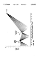
- FIGS. 9A, 9B and 9C illustrate the diameter of the laser beams within the optical system as a function of the distance from the laser cavity and as a function of pump power.
- FIG. 10 is a block schematic diagram of the cooling system for the laser system of the present invention.
- FIG. 11 shows the relationship of the laser heads in the cooling system.
- FIG. 12 illustrates the heat exchanger of FIG. 11 in greater detail.
- FIGS. 1-4 a solid state laser 10 is shown having four separate laser head assemblies 11-14. Associated with each laser head assembly are a pair of resonator mirrors 16 and 18 which define the laser cavity for each of the laser heads. Each of the mirrors 16 is totally reflecting and each of the mirrors 18 is partially transmissive in the standard manner.
- output beams 20, 22, 24 and 26 are provided for laser heads 11-14.
- the laser heads 11-14 are held and supported by a head support structure 28, which includes a horizontal support 30, shown in FIG. 2 which has a central hole 32.
- the interleaved pulsed output beam 34 from laser 10 passes through hole 32.
- An optical path 36 is provided for each of the pulsed laser beam outputs 22, 24, 26 and 28 which includes mirror 38, a reflector 40 and a rotatable reflecting wedge 42.
- the output for each of the laser head assemblies is imaged on the mirror 38, which has a curved surface to focus the beam on the rotatable reflecting wedge 42.
- Reflector 40 is a mirror which is flat with no curvature.
- the surface of the reflecting wedge 42 from which the interleaved output beam 34 is formed has a curved surface so the output beam may be focused by a lens 35, for example, on the face of a fiber-optic surgical delivery tube.
- Each of the resonator mirrors 16 are supported in mirror mounts, which are adjustably secured to a first resonator support 46, having a central hole 48 for passage of the output beam 34.
- mirrors 18 are supported by mirror mounts 50 which are adjustably mounted to a second resonator support 52, which also supports reflector mounts 54.
- the rotatable reflecting wedge 42 is rotated by motor 56 both of which are mounted to support 58.
- Support 58 also secures mount 60 of output coupler 38 in an adjustable fashion.
- the rotatable reflector 42 is rotated sequentially to each of four positions.
- the reflector 42 When the reflector 42 is stopped in one of the four positions it provides an optical path, in combination with reflectors 38 and 40, from one of the laser heads 11-14 along a common output path 34.
- the corresponding laser head is energized to provide a laser pulse onto the surface of rotatable reflector 42 and then along the output path 34.
- a composite, interleaved pulsed laser output is provided from reflector 42 along the output path 34.
- FIG. 5 shows one actual laser head assembly 11, in accordance with the present invention, of a type referred to as a diffuse reflector.
- the active lasing medium is a cylindrical Ho:YAG laser rod 62.
- the laser rod 62 fits within a first channel 64 of an oval-shaped, elongated dynasil glass enclosure 66.
- a second channel 68 in glass enclosure 66 houses an elongated flashlamp 70 for optically pumping laser rod 62. Flashlamp 70 is terminated with terminals 72 and 74.
- Surrounding the glass enclosure 66 is a jacket of BaSO 4 76 which acts as a light reflector to maximize the efficiency of the pump source 70.
- the combination of the BaSO 4 76 and glass enclosure 66 is encased in an aluminum housing 78.
- Cooling for each of the laser head assembly does not require refrigeration, since each laser rod 62 is not pumped for maximum output. That is, the pump energy per laser pulse times the pulse rate is less for the laser of the present invention than typically used in a Ho:YAG laser with refrigeration cooling. Cooling is carried out by passing de-ionized water through the head assembly. Cooling water passes into inlet 80, through the laser head block 82 and out of outlet 84. A plug 86 permits access to the block 82.
- the Ho:YAG rod 62 is 31/2 inches long and has a diameter of 4 mm.
- FIG. 6 is a schematic diagram of the high voltage power supply 87 for sequentially triggering each of the flashlamps 70, which in turn pump each of the laser rods 62.
- Each of the flashlamps has associated with it an external trigger wire 38, which in turn is connected to an individual simmer power supply 90-93.
- Power supplies 90-93 maintain a sufficient electric field on each of the trigger wires 88 so that the gas within the flashlamps 70 is ionized and conducting. However, the level of conduction, approximately 100 milliamps, is low and so not enough light is emitted to trigger lasing of the rods 62.
- SCRs 96-99 Connected in series with the flashlamps 70 are SCRs 96-99, having gate electrodes 102-105, respectively. Each SCR is also connected to an inductor 108 and a capacitor 110. Capacitor 110 is charged by a regulated constant current source 112, which charges the capacitor 110 to approximately 1.5 KV.
- the flashlamps 70 are sequentially energized to a level which provides a high power burst of light to sequentially energize laser rods 62 in laser heads 11-14. This is accomplished by sequentially turning each of the SCRs 96-99 from an "off” state to an “on” state by putting a signal on the appropriate gate electrode 102-105. When this happens, capacitor 110 is discharged through the selected flashlamp 70.
- FIG. 7 is a block schematic diagram of the capacitor and SCR control circuit 114.
- An encoder 116 senses the position of the rotating reflecting wedge 42. This positional information is fed a microprocessor 118, which in turn controls the sequence and timing of the switching of SCRs 96-99. That is, when the rotating wedge is in position to accept the output beam from laser head 11, the SCR of the corresponding flashlamp is turned on via line 119 and the corresponding laser rod is energized. This occurs again each time the rotating wedge 42 is ready for the beam from the next laser head.
- Each of the laser rods 62 has a somewhat different efficiency associated with it. Since it is important that the composite output beam 34 have pulses of the same magnitude, this difference in individual laser rods must be accounted for. This is accomplished by controlling the regulated current source 112 and the level to which capacitor 110 is charged.
- microprocessor 118 The output power of each laser rod is measured empirically and the degree to which the capacitor must be charged to maintain equal output pulses from each laser rod is stored in a look-up table in microprocessor 118. Additionally, feedback is provided to maintain constant output pulses. An optical pick-off 120 samples each output pulse and a signal indicative of the magnitude of the pulse is sent to microprocessor 118. Based upon the look-up table and the fact that the output from each flashlamp is proportional to the square of the voltage on capacitor 110, microprocessor 118, by controlling current source 112, controls the voltage stored on capacitor 110 for each laser rod, which in turn determines the output from each flashlamp.
- motor 56 is supplied by the Escape Co. It makes one full revolution every 100 milliseconds. It makes a stop four times, for a stop time period of 5 msec.
- Capacitor 110 is one actual embodiment is 140 uf and inductor 108 is 300 microhenries. Flashlamps 70 have cerium-doped quartz envelopes and are filled with xenon gas at a pressure of 1000 torr. The combined power from the four flashlamps 70 is approximately 5000 watts.
- FIG. 8 is a timing diagram showing the relationship between the outputs from each of the individual rods.
- each is pulsed at a 10 Hz repetition rate.
- the resulting interleaved output beam 34 has a repetition rate of 40 Hz.
- the present invention is not limited to a particular number of individual rods or a particular repetition rate. What is important is that the average pump power be kept below that for maximum output power for any given rod. Since power is equal to the pump energy times the pump repetition rate, both can be varied in pumping the individual laser rods sufficient time following each pump input light pulse to allow thermal relaxation in the laser rods, so that temperature build-up is not sufficiently large to require refrigeration cooling.
- the individual lasers to be combined need not be of the same wavelengths, so that the affects on tissue can be varied. That is, the individual laser rods may be of different materials resulting in different pulse characteristics within the interleaved output 34.
- the optical system of the present invention is unique in several respects. It is both compact and it provides an interleaved output beam whose size (diameter) is independent of pump power, and even though thermal lensing gets stronger as the laser rods are pumped at greater power levels.
- the optical system also is unique in that it provides a laser beam of constant numerical aperture (beam divergence) inside an optical fiber delivery system. Also, it is arranged in a way that even if the rotating reflector 42 is somewhat out of position relative to the laser beams, the action of the laser beam at the input to the optical fiber remains fairly constant. To realize all three features at the same time, the point of constant beam diameter inside the laser is first imaged onto the moving element and this image is then relayed to the input end of the fiber. Simultaneously, the second point of constant image size is imaged to the focusing lens that produces the final image on the fiber.
- the x-axis represents the distance as measured along the optical path from one of the output couplers 18 of one of the laser heads 11-14.
- the y-axis represents the beam diameter from the laser head and the series of lines represent the beam diameter as a function of the pump power. It can be seen, for example, that the output beam diameter varies from 1 to 4 mm, depending upon the pump power.
- the laser resonator is designed to image the beam to a spot 125 which corresponds to the surface of the curved mirror 38, which is positioned approximately 15 cm from output coupler 18.
- the mirror 38 is concave with a curve to re-focus the laser beam to a spot 127, which corresponds to the surface of the rotatable mirror 42. As can be seen from FIG. 9A and and FIG. 1 this occurs at a distance of approximately 40 cm from output coupler 18.
- Rotatable mirror 42 also has concave, curved, surface and focuses the beam to a spot 129 on lens 35, which may be part of an optical fiber surgical delivery tube 37, where lens 35 focuses the beam, in the well-known manner, onto one end of an optical fiber or fiber bundle 37.
- the limit in the width of the gain medium defines a point where the beam width is constant regardless of laser power. That is to say, that at a point within each of the laser cavities the laser beam has the same width as the gain medium.
- the output coupler 18 re-focuses an image of this point, corresponding to spot 127, onto the rotatable mirror 42, and thereafter the image of this point is refocused by lens 35 at the input to the optical fiber 37. In this manner the output laser beam provided to the input to the optical fiber surgical delivery tube will be the same size regardless of pump power. This is seen graphically in FIG. 9B. Point 131 is the location of the input to fiber focal lens 35.
- the system is configured so that the image on the rotatable mirror 42 is re-imagined by lens 35 on the optical fiber 37.
- rotation of the moving element produces only a rotation of the element on the fiber 37, but no translation of the image on the fiber. Consequently small errors in the position of rotatable mirror 42 do not produce errors in the location of the laser beam at the input to fiber 37. Instead variations in the position of the moving element produce small changes in the input angle of the beam inside fiber 37.
- the optical fibers tend to be more tolerant of these errors.
- resonator mirror or coupler 16 has a radius of curvature of 100 cm and is located 11 cm from one end of the Ho:YAG laser rod 62.
- Output coupler 18, which is 84% reflecting within the laser cavity, is provided with an outside convex curvature, with a radius of curvature of 30 cm.
- Coupler 18 is positioned 11 cm from the opposite end of the Ho:YAG laser rod 62.
- Reflector 38 has a focal length of 13.47 cm
- rotatable reflector 42 has a focal length of 18.24 cm
- lens 35 has a focal length of 2.4 cm.
- Each of the reflectors 40 in combination with the other optical components, provides an important function of allowing the optical system to be compact. Also, reflectors 40 allow each of the beams 22, 24, 26 and 28 from the individual lasers, to be directed at rotatable reflector 42 at small angle to the interleaved output beam 34. This allows the mechanical components, including the rotatable reflector 42, to have greater mechanical tolerances, thereby making the system less expensive to manufacture and maintain. Mirror 38 and rotatable mirror 42 need not be reflectors. They can be built as convex lenses as well.
- FIG. 10 illustrates details of the cooling system 135 used in one actual embodiment to cool laser heads 11-14.
- a single pump 137 is used for all of the laser heads.
- Pump 137 is a positive-displacement pump which provides a constant flow of about 4 gallons/min of water coolant, regardless of pressure.
- a deionizing cartridge 139 is put in parallel with the main conduit 140, to keep the water-coolant non-conducting.
- a flow switch 143 provides the safety function of shutting down the system if no water is circulating. Prior to entering the laser heads the cooling water passes through a filter 145 to remove particulate material.
- the cooling water passes at 147 through the laser heads, which are arranged with 2 laser heads in series with each other, and each pair in parallel with each other. This arrangement is shown in FIG. 11.
- the resulting flow through each laser head is approximately 1 gallon per minute.
- a very small space 67 of 0.4 mm is provided between the glass enclosure 70 and around each laser rod 62.
- Space 69 also is provided around the flashlamps 70 so they are cooled along with the laser rods.
- the cooling water now heated, flows through a heat exchange system 149 which is air-cooled by a fan (not shown) in the well-known manner.
- Water exits the heat exchanger at near ambient temperatures and then flows through a venturi 151 which introduces turbulence into the flow.
- the water then flows into a main holding tank 151 which acts in a manner equivalent to a mechanical "fly wheel.” That is, by having a tank with the capacity to store several gallons of water, the lasers can be operated at maximum output power for extended periods of time, since the additional water in the system can absorb additional heat generated in the laser heads.
- a fill tank 153 is used to "top-off" the main tank 151 as is necessary.
- the actual heat exchanger 160 is conventional with a water inlet 162 and a water outlet 164. Coils of pipes thru which the water flows (not shown) are provided within the heat exchanger 160. Air for cooling enters at the bottom of the heat exchanger 160 and exits from the top.
- Air is drawn thru the heat exchanger by a backward curved impeller fan driven by a fan motor 168.
- a characteristic of such a fan is that air enters the fan axially, in this case at the bottom, and is then expelled radially, as shown by the arrows in FIG. 12.
- the heat exchanger is very compact, measuring approximately 1 foot square and 5 inches in thickness. Such a heat exchanger requires large volumes of air to pass thru it, resulting of a large pressure drop across it.
- the use of a backward curved impeller is ideal for this application because it is compact, powerful, and directs the air out radially.
- the optical pump repetition rate for the laser rods can be as high as 7 Hz with no loss in output power. As the repetition rate gets higher the output begins to drop because the thermal time constant of the Ho:YAG rod doesn't allow sufficient thermal relaxation to occur. Above approximately 10 Hz the output drops more rapidly. It should be noted, however, that the specifics of the foregoing characteristics will change depending upon the pump and optical systems and the individual laser rod design.
Abstract
Description
Claims (16)
Priority Applications (4)
| Application Number | Priority Date | Filing Date | Title |
|---|---|---|---|
| US08/331,359 US5659563A (en) | 1993-05-05 | 1994-10-27 | Solid state laser with relay optics |
| US08/873,823 US5781574A (en) | 1993-05-05 | 1997-06-12 | Liquid circulation system for cooling a laser head |
| US09/105,874 US5999555A (en) | 1993-05-05 | 1998-06-26 | Apparatus for combining laser beams |
| US09/382,405 US6115396A (en) | 1993-05-05 | 1999-08-24 | Control system for a laser with multiple solid state rods |
Applications Claiming Priority (2)
| Application Number | Priority Date | Filing Date | Title |
|---|---|---|---|
| US08/057,084 US5375132A (en) | 1993-05-05 | 1993-05-05 | Solid state laser with interleaved output |
| US08/331,359 US5659563A (en) | 1993-05-05 | 1994-10-27 | Solid state laser with relay optics |
Related Parent Applications (1)
| Application Number | Title | Priority Date | Filing Date |
|---|---|---|---|
| US08/057,084 Division US5375132A (en) | 1993-05-05 | 1993-05-05 | Solid state laser with interleaved output |
Related Child Applications (1)
| Application Number | Title | Priority Date | Filing Date |
|---|---|---|---|
| US08/873,823 Division US5781574A (en) | 1993-05-05 | 1997-06-12 | Liquid circulation system for cooling a laser head |
Publications (1)
| Publication Number | Publication Date |
|---|---|
| US5659563A true US5659563A (en) | 1997-08-19 |
Family
ID=22008400
Family Applications (5)
| Application Number | Title | Priority Date | Filing Date |
|---|---|---|---|
| US08/057,084 Expired - Lifetime US5375132A (en) | 1993-05-05 | 1993-05-05 | Solid state laser with interleaved output |
| US08/331,359 Expired - Fee Related US5659563A (en) | 1993-05-05 | 1994-10-27 | Solid state laser with relay optics |
| US08/873,823 Expired - Fee Related US5781574A (en) | 1993-05-05 | 1997-06-12 | Liquid circulation system for cooling a laser head |
| US09/105,874 Expired - Lifetime US5999555A (en) | 1993-05-05 | 1998-06-26 | Apparatus for combining laser beams |
| US09/382,405 Expired - Lifetime US6115396A (en) | 1993-05-05 | 1999-08-24 | Control system for a laser with multiple solid state rods |
Family Applications Before (1)
| Application Number | Title | Priority Date | Filing Date |
|---|---|---|---|
| US08/057,084 Expired - Lifetime US5375132A (en) | 1993-05-05 | 1993-05-05 | Solid state laser with interleaved output |
Family Applications After (3)
| Application Number | Title | Priority Date | Filing Date |
|---|---|---|---|
| US08/873,823 Expired - Fee Related US5781574A (en) | 1993-05-05 | 1997-06-12 | Liquid circulation system for cooling a laser head |
| US09/105,874 Expired - Lifetime US5999555A (en) | 1993-05-05 | 1998-06-26 | Apparatus for combining laser beams |
| US09/382,405 Expired - Lifetime US6115396A (en) | 1993-05-05 | 1999-08-24 | Control system for a laser with multiple solid state rods |
Country Status (4)
| Country | Link |
|---|---|
| US (5) | US5375132A (en) |
| EP (1) | EP0697143A1 (en) |
| JP (1) | JPH08509843A (en) |
| WO (1) | WO1994026010A2 (en) |
Cited By (11)
| Publication number | Priority date | Publication date | Assignee | Title |
|---|---|---|---|---|
| US20010016732A1 (en) * | 1998-02-03 | 2001-08-23 | James L. Hobart | Dual mode laser delivery system providing controllable depth of tissue ablation and corresponding controllable depth of coagulation |
| US6575964B1 (en) | 1998-02-03 | 2003-06-10 | Sciton, Inc. | Selective aperture for laser delivery system for providing incision, tissue ablation and coagulation |
| US20030219094A1 (en) * | 2002-05-21 | 2003-11-27 | Basting Dirk L. | Excimer or molecular fluorine laser system with multiple discharge units |
| US6678308B1 (en) * | 2002-09-06 | 2004-01-13 | The Boeing Company | Laser resonator system using offner relay |
| US6743221B1 (en) | 2001-03-13 | 2004-06-01 | James L. Hobart | Laser system and method for treatment of biological tissues |
| US6770069B1 (en) | 2001-06-22 | 2004-08-03 | Sciton, Inc. | Laser applicator |
| US6904075B1 (en) * | 1999-07-30 | 2005-06-07 | Mitsubishi Denki Kabushiki Kaisha | Orthogonal gas laser device |
| US20060251141A1 (en) * | 2005-05-06 | 2006-11-09 | Mefferd Wayne S | Optically pumped external-cavity semiconductor laser with multiple gain structures |
| US20120155503A1 (en) * | 2010-10-23 | 2012-06-21 | Jan Vetrovec | Solid-state laser with multi-pass beam delivery optics |
| US20130322471A1 (en) * | 2012-06-04 | 2013-12-05 | The Boeing Company | Modal Corrector Mirror With Compliant Actuation For Optical Aberrations |
| US20180366896A1 (en) * | 2017-06-20 | 2018-12-20 | Boston Scientific Scimed, Inc. | Laser systems and methods |
Families Citing this family (40)
| Publication number | Priority date | Publication date | Assignee | Title |
|---|---|---|---|---|
| US5528612A (en) * | 1993-11-19 | 1996-06-18 | The United States Of America As Represented By The Secretary Of The Navy | Laser with multiple gain elements |
| WO1996033538A1 (en) * | 1995-04-17 | 1996-10-24 | Coherent, Inc. | High repetition rate erbium: yag laser for tissue ablation |
| FR2737814B1 (en) * | 1995-08-11 | 1997-09-12 | Soc D Production Et De Rech Ap | METHOD AND DEVICE FOR CONTROLLING A LASER SOURCE WITH MULTIPLE LASER MODULES TO OPTIMIZE LASER SURFACE TREATMENT |
| JP3067686B2 (en) * | 1997-04-21 | 2000-07-17 | 日本電気株式会社 | Solid-state laser device |
| FR2765413B1 (en) * | 1997-06-27 | 1999-07-30 | Commissariat Energie Atomique | MULTIPLE HEAD LASER DEVICE |
| US6320993B1 (en) | 1998-06-05 | 2001-11-20 | Astarte Fiber Networks, Inc. | Optical switch pathway configuration using control signals |
| RU2267143C2 (en) | 1998-06-05 | 2005-12-27 | Эй Эф Эн Ллк | Optical switch( variants ), optical switching device( variants ) and mode of switching of an optical signal |
| FR2814599B1 (en) * | 2000-09-27 | 2005-05-20 | Commissariat Energie Atomique | HIGH-STRENGTH LASER DEVICE CREATED AND APPLICATION TO LIGHT GENERATION IN EXTREME ULTRA VIOLET |
| US6904069B2 (en) * | 2000-12-29 | 2005-06-07 | The Regents Of The University Of California | Parasitic oscillation suppression in solid state lasers using optical coatings |
| US20050259709A1 (en) | 2002-05-07 | 2005-11-24 | Cymer, Inc. | Systems and methods for implementing an interaction between a laser shaped as a line beam and a film deposited on a substrate |
| US6928093B2 (en) * | 2002-05-07 | 2005-08-09 | Cymer, Inc. | Long delay and high TIS pulse stretcher |
| US6765941B2 (en) | 2001-12-03 | 2004-07-20 | Agfa Corporation | Method and apparatus for cooling a self-contained laser head |
| US7058100B2 (en) | 2002-04-18 | 2006-06-06 | The Boeing Company | Systems and methods for thermal management of diode-pumped solid-state lasers |
| US6647049B1 (en) * | 2002-12-27 | 2003-11-11 | General Atomics | Iodine on-demand system for a chemical laser |
| US7277188B2 (en) | 2003-04-29 | 2007-10-02 | Cymer, Inc. | Systems and methods for implementing an interaction between a laser shaped as a line beam and a film deposited on a substrate |
| JP2006237540A (en) * | 2004-03-30 | 2006-09-07 | Ricoh Co Ltd | Solid laser apparatus by semiconductor laser exciting |
| US7427289B2 (en) * | 2005-01-14 | 2008-09-23 | Cynosure, Inc. | Multiple wavelength laser workstation |
| US20070014517A1 (en) * | 2005-05-25 | 2007-01-18 | Biolase Technology, Inc. | Electromagnetic energy emitting device with increased spot size |
| US20060293644A1 (en) * | 2005-06-21 | 2006-12-28 | Donald Umstadter | System and methods for laser-generated ionizing radiation |
| US7317179B2 (en) | 2005-10-28 | 2008-01-08 | Cymer, Inc. | Systems and methods to shape laser light as a homogeneous line beam for interaction with a film deposited on a substrate |
| US7679029B2 (en) | 2005-10-28 | 2010-03-16 | Cymer, Inc. | Systems and methods to shape laser light as a line beam for interaction with a substrate having surface variations |
| US20070263684A1 (en) | 2006-05-09 | 2007-11-15 | Nolan John F | Method and system for cooling and pressurizing an imaging head |
| JP5499432B2 (en) * | 2007-10-05 | 2014-05-21 | ソニー株式会社 | Imaging device |
| CN101256255B (en) * | 2008-03-21 | 2010-10-13 | 北京理工大学 | System for joining light path of multiplex laser |
| US8774244B2 (en) * | 2009-04-21 | 2014-07-08 | Daylight Solutions, Inc. | Thermal pointer |
| US8509272B2 (en) * | 2009-06-10 | 2013-08-13 | Lee Laser, Inc. | Laser beam combining and power scaling device |
| CN101814693A (en) * | 2010-04-01 | 2010-08-25 | 深圳市大族激光科技股份有限公司 | laser |
| US8599891B2 (en) | 2011-03-21 | 2013-12-03 | Soreq Nuclear Research Center | Laser diode driver |
| CN102570265B (en) * | 2011-05-25 | 2014-01-08 | 北京国科世纪激光技术有限公司 | Device and method for improving working frequency of lamp pump laser amplifiers |
| CN102570263B (en) * | 2011-09-28 | 2013-10-30 | 北京国科世纪激光技术有限公司 | Device and method for improving working frequencies of lamp pump laser amplifiers |
| CN102354908B (en) * | 2011-11-02 | 2012-11-21 | 浙江大学 | Method for improving output peak power of semiconductor laser unit |
| CN102621695A (en) * | 2012-03-22 | 2012-08-01 | 华中科技大学 | Pulse laser beam combining method |
| RU2532649C2 (en) * | 2012-12-29 | 2014-11-10 | федеральное государственное автономное образовательное учреждение высшего образования "Санкт-Петербургский национальный исследовательский университет информационных технологий, механики и оптики" | Pancratic focusing system |
| CN103064157A (en) * | 2013-01-05 | 2013-04-24 | 中国科学院合肥物质科学研究院 | Multichannel laser fiber coupling device |
| US9220563B1 (en) | 2014-12-29 | 2015-12-29 | InnovaQuartz LLC | Multiwavelength surgical laser |
| CN104659641A (en) * | 2015-02-13 | 2015-05-27 | 合肥大族科瑞达激光设备有限公司 | Four-way holmium laser with four-cavity space |
| US20160294148A1 (en) * | 2015-04-01 | 2016-10-06 | Lumenis Ltd. | High efficiency laser cavity |
| WO2017211375A1 (en) | 2016-06-10 | 2017-12-14 | MAX-PLANCK-Gesellschaft zur Förderung der Wissenschaften e.V. | Optical beam switch apparatus, beam switching method and applications thereof |
| WO2019094722A1 (en) * | 2017-11-10 | 2019-05-16 | Boston Scientific Scimed, Inc. | Apparatus and methodology for reshaping a laser beam |
| KR102004169B1 (en) * | 2019-01-30 | 2019-07-29 | 원텍 주식회사 | Medical multi-laser amplification output device |
Citations (29)
| Publication number | Priority date | Publication date | Assignee | Title |
|---|---|---|---|---|
| US3322231A (en) * | 1964-12-29 | 1967-05-30 | Mobil Oil Corp | Methods and systems utilizing lasers for generating seismic energy |
| US3543183A (en) * | 1965-06-23 | 1970-11-24 | Ringsdorff Werke Gmbh | Apparatus for the development of a coherent monochromatic light beam |
| US3924937A (en) * | 1974-01-30 | 1975-12-09 | Jersey Nuclear Avco Isotopes | Method and apparatus for sequentially combining pulsed beams of radiation |
| FR2293086A1 (en) * | 1974-11-28 | 1976-06-25 | Bret Georges | Correction of induced deformation in light amplifier - using cooling liq to maintain amplifying medium temp constant |
| US3983511A (en) * | 1975-09-08 | 1976-09-28 | Sanders Associates, Inc. | Normal incidence face pumped disc laser |
| US4097235A (en) * | 1975-06-05 | 1978-06-27 | Firma Hermann Stock | Autoclave and autoclave system |
| US4154507A (en) * | 1977-12-08 | 1979-05-15 | Jersey Nuclear-Avco Isotopes, Inc. | Optical combiner/distributor using V-shaped mirror assembly |
| US4217558A (en) * | 1976-03-03 | 1980-08-12 | Trw Inc. | Pulsed chemical laser system |
| US4243942A (en) * | 1978-01-11 | 1981-01-06 | The United States Of America As Represented By The United States Department Of Energy | Fully relayed regenerative amplifier |
| US4311360A (en) * | 1980-04-07 | 1982-01-19 | Rockwell International Corporation | Laser beam power multiplication |
| US4520472A (en) * | 1983-02-07 | 1985-05-28 | Rca Corporation | Beam expansion and relay optics for laser diode array |
| FR2578691A1 (en) * | 1985-03-06 | 1986-09-12 | Bouchlaghem Daniel | Laser generator with adjustable power |
| US4677636A (en) * | 1985-10-23 | 1987-06-30 | The United States Of America As Represented By The Administrator Of The National Aeronautics And Space Administration | Multiplex electric discharge gas laser system |
| US4732460A (en) * | 1986-07-01 | 1988-03-22 | Coherent, Inc. | Beam selector for a photocoagulator |
| DE3904287A1 (en) * | 1988-02-15 | 1989-09-07 | Kurt Dr Schirmer | Arrangement for cutting with laser beams |
| US4922502A (en) * | 1987-06-30 | 1990-05-01 | Hoya Corporation | Solid-state laser device comprising a plurality of excitation units selectively energized |
| US4953950A (en) * | 1987-04-30 | 1990-09-04 | Yoshiaki Arata | Apparatus for producing ultra-high power ultra-high density laser beam |
| US4991182A (en) * | 1989-09-22 | 1991-02-05 | Rockwell International Corporation | Optical relay imaging in the common pass annular laser amplifier |
| US4998259A (en) * | 1990-03-29 | 1991-03-05 | The United States Of America As Represented By The Secretary Of The Army | Gatling gun laser pulse amplifier using rotating mirrors |
| US5001718A (en) * | 1989-06-02 | 1991-03-19 | Lumonics, Ltd. | Telescopic thermal lens compensating laser |
| US5025446A (en) * | 1988-04-01 | 1991-06-18 | Laserscope | Intra-cavity beam relay for optical harmonic generation |
| US5052017A (en) * | 1988-12-01 | 1991-09-24 | Coherent, Inc. | High power laser with focusing mirror sets |
| DE4009859A1 (en) * | 1990-03-28 | 1991-10-02 | Fraunhofer Ges Forschung | High power laser beam prodn. - by combining successive laser pulses from separate solid state lasers |
| US5088103A (en) * | 1990-04-30 | 1992-02-11 | The United States Of America As Represented By The Secretary Of The Navy | Room-temperature, flashpumped, 2.09 micron solid state laser |
| US5095383A (en) * | 1989-09-29 | 1992-03-10 | Kabushiki Kaisha Toshiba | Optical unit for use in a laser beam printer or the like |
| US5172264A (en) * | 1991-02-21 | 1992-12-15 | Surgilase, Inc. | Method and apparatus for combining continuous wave laser with TEA pulsed laser |
| US5336216A (en) * | 1991-10-10 | 1994-08-09 | Coherent, Inc. | Apparatus for delivering a defocused laser beam having a sharp-edged cross-section |
| GB2276014A (en) * | 1993-03-10 | 1994-09-14 | Trimedyne Inc | Multi-head combined beam laser assembly |
| US5355387A (en) * | 1992-07-14 | 1994-10-11 | The United States Of America As Represented By The United States Department Of Energy | Interface module for transverse energy input to dye laser modules |
Family Cites Families (52)
| Publication number | Priority date | Publication date | Assignee | Title |
|---|---|---|---|---|
| US3310753A (en) * | 1963-02-07 | 1967-03-21 | Martin Marietta Corp | Sequentially firing array of laser units |
| US3444479A (en) * | 1965-02-02 | 1969-05-13 | Sylvania Electric Prod | Method and apparatus for producing a frequency modulated laser beam |
| US3443243A (en) * | 1965-06-23 | 1969-05-06 | Bell Telephone Labor Inc | Frequency selective laser |
| US3428812A (en) * | 1965-10-22 | 1969-02-18 | Nasa | Optical spin compensator |
| US3602572A (en) * | 1968-12-03 | 1971-08-31 | Westinghouse Electric Corp | Two-dimensional optical beam scanner |
| US3638140A (en) * | 1969-07-28 | 1972-01-25 | Hughes Aircraft Co | Laser-cooling system |
| US3665338A (en) * | 1969-10-28 | 1972-05-23 | Synergetics Research Inc | Variable frequency infra red source |
| US3731110A (en) * | 1971-07-12 | 1973-05-01 | Laser system for producing wavelength-tunable optical radiation | |
| US3772609A (en) * | 1972-06-30 | 1973-11-13 | Us Army | Laser cavity configuration yielding dual output beam |
| US3817604A (en) * | 1973-01-03 | 1974-06-18 | Atomic Energy Commission | Method of focusing a high-powered laser beam |
| JPS5643635B2 (en) * | 1973-03-26 | 1981-10-14 | ||
| US4114112A (en) * | 1976-12-22 | 1978-09-12 | Northwestern University | Apparatus and method for efficient synthesis of laser light |
| US4283116A (en) * | 1977-04-22 | 1981-08-11 | Jersey Nuclear-Avco Isotopes, Inc. | Beam combiner |
| GB2007014B (en) * | 1977-10-04 | 1982-03-31 | Commissariat Energie Atomique | Fast-switching multiwavelength laser |
| DE2809007A1 (en) * | 1978-03-02 | 1979-09-13 | Messerschmitt Boelkow Blohm | Live tissue cutting and coagulating instrument - has two different wavelength laser beams and pilot light(s) passed together through manipulator to emerge coaxially from it |
| US4338578A (en) * | 1980-03-05 | 1982-07-06 | Yefim Sukhman | Multicolor pulsed coherent-light source |
| US4408602A (en) * | 1981-01-14 | 1983-10-11 | Asahi Kogaku Kogyo Kabushiki Kaisha | Laser knife device |
| JPS5844784A (en) * | 1981-09-11 | 1983-03-15 | Nippon Sekigaisen Kogyo Kk | Laser device |
| JPS5886787A (en) * | 1981-11-19 | 1983-05-24 | Nippon Sekigaisen Kogyo Kk | Laser emitting device |
| US4441186A (en) * | 1981-12-31 | 1984-04-03 | Gte Products Corporation | Electronically switchable multiwavelength laser system |
| US4450563A (en) * | 1982-04-23 | 1984-05-22 | Westinghouse Electric Corp. | Rapidly turnable laser system |
| US4502144A (en) * | 1982-06-10 | 1985-02-26 | Westinghouse Electric Corp. | Gain tuned laser resonator |
| JPS5914848A (en) * | 1982-07-15 | 1984-01-25 | 株式会社トプコン | Light treating apparatus |
| US4601036A (en) * | 1982-09-30 | 1986-07-15 | Honeywell Inc. | Rapidly tunable laser |
| US4473673A (en) * | 1983-05-09 | 1984-09-25 | Wildon Industries, Inc. | Cast polyester resin process and product |
| US4672969A (en) * | 1983-10-06 | 1987-06-16 | Sonomo Corporation | Laser healing method |
| JPS60149232A (en) * | 1984-01-17 | 1985-08-06 | Nec Corp | Relay broadcasting device |
| US4627068A (en) * | 1984-06-13 | 1986-12-02 | The United States Of America As Represented By The Department Of Energy | Fiber optics interface for a dye laser oscillator and method |
| US4910746A (en) * | 1984-06-14 | 1990-03-20 | Peter Nicholson | Multiple crystal pumping cavity laser with thermal and mechanical isolation |
| US4674096A (en) * | 1985-03-04 | 1987-06-16 | California Institute Of Technology | Lateral coupled cavity semiconductor laser |
| DE3508707A1 (en) * | 1985-03-12 | 1986-09-18 | Battelle-Institut E.V., 6000 Frankfurt | ARRANGEMENT FOR FAST SWITCHING BETWEEN DIFFERENT WAVELENGTHS WITH LASERS |
| JPS6211285A (en) * | 1985-07-09 | 1987-01-20 | Toshiba Corp | Laser apparatus |
| US4917084A (en) * | 1985-07-31 | 1990-04-17 | C. R. Bard, Inc. | Infrared laser catheter system |
| US4674091A (en) * | 1985-08-14 | 1987-06-16 | The United States Of America As Represented By The Secretary Of The Air Force | Methods for tuning free electron lasers to multiple wavelengths |
| US4761059A (en) * | 1986-07-28 | 1988-08-02 | Rockwell International Corporation | External beam combining of multiple lasers |
| US4751706A (en) * | 1986-12-31 | 1988-06-14 | The United States Of America As Represented By The Secretary Of The Army | Laser for providing rapid sequence of different wavelengths |
| DE3704338C2 (en) * | 1987-02-12 | 1995-04-06 | Gsf Forschungszentrum Umwelt | Device for generating different laser wavelengths from the same laser medium |
| US4818049A (en) * | 1987-06-10 | 1989-04-04 | Allied-Signal Inc. | Method and apparatus for efficiently conveying light over a distance and effecting controlled illumination by projection thereof |
| JPS6429877A (en) * | 1987-07-24 | 1989-01-31 | Asahi Optical Co Ltd | Energy modulating device for semiconductor laser |
| US5037421A (en) * | 1989-10-06 | 1991-08-06 | Coherent, Inc., Medical Group | Mid-infrared laser arthroscopic procedure |
| JPH0260179A (en) * | 1988-08-26 | 1990-02-28 | Fuji Photo Film Co Ltd | Laser ray source device for wave multiplexing |
| EP0368512A3 (en) * | 1988-11-10 | 1990-08-08 | Premier Laser Systems, Inc. | Multiwavelength medical laser system |
| IL88722A (en) * | 1988-12-19 | 1993-03-15 | Israel State | Holmium laser |
| JPH07117668B2 (en) * | 1988-12-28 | 1995-12-18 | 富士写真フイルム株式会社 | Optical amplifier |
| US4982166A (en) * | 1989-03-01 | 1991-01-01 | Morrow Clifford E | Method and apparatus for combining two lower power laser beams to produce a combined higher power beam |
| US5327442A (en) * | 1992-02-19 | 1994-07-05 | Coherent, Inc. | Solid state laser with dual cooling loops |
| EP0568727B1 (en) * | 1992-05-06 | 1997-07-23 | Electrox Ltd. | Laser beam combination system |
| US5278404A (en) * | 1992-07-20 | 1994-01-11 | At&T Bell Laboratories | Optical sub-system utilizing an embedded micro-controller |
| US5272713A (en) * | 1992-08-27 | 1993-12-21 | Spectra-Physics Lasers, Inc. | High repetition rate pulsed laser |
| US5390204A (en) * | 1992-09-25 | 1995-02-14 | Incisive Technologies, Inc. | Intracavity modulated pulsed laser with a variably controllable modulation frequency |
| US5353293A (en) * | 1993-04-27 | 1994-10-04 | Spectra-Physics Lasers, Inc. | Hybrid cooled ion laser |
| US5481556A (en) * | 1993-10-01 | 1996-01-02 | S.L.T. Japan Co., Ltd. | Laser oscillation apparatus with cooling fan and cooling fins |
-
1993
- 1993-05-05 US US08/057,084 patent/US5375132A/en not_active Expired - Lifetime
-
1994
- 1994-04-07 WO PCT/US1994/003810 patent/WO1994026010A2/en not_active Application Discontinuation
- 1994-04-07 JP JP6524290A patent/JPH08509843A/en active Pending
- 1994-04-07 EP EP94928701A patent/EP0697143A1/en not_active Withdrawn
- 1994-10-27 US US08/331,359 patent/US5659563A/en not_active Expired - Fee Related
-
1997
- 1997-06-12 US US08/873,823 patent/US5781574A/en not_active Expired - Fee Related
-
1998
- 1998-06-26 US US09/105,874 patent/US5999555A/en not_active Expired - Lifetime
-
1999
- 1999-08-24 US US09/382,405 patent/US6115396A/en not_active Expired - Lifetime
Patent Citations (29)
| Publication number | Priority date | Publication date | Assignee | Title |
|---|---|---|---|---|
| US3322231A (en) * | 1964-12-29 | 1967-05-30 | Mobil Oil Corp | Methods and systems utilizing lasers for generating seismic energy |
| US3543183A (en) * | 1965-06-23 | 1970-11-24 | Ringsdorff Werke Gmbh | Apparatus for the development of a coherent monochromatic light beam |
| US3924937A (en) * | 1974-01-30 | 1975-12-09 | Jersey Nuclear Avco Isotopes | Method and apparatus for sequentially combining pulsed beams of radiation |
| FR2293086A1 (en) * | 1974-11-28 | 1976-06-25 | Bret Georges | Correction of induced deformation in light amplifier - using cooling liq to maintain amplifying medium temp constant |
| US4097235A (en) * | 1975-06-05 | 1978-06-27 | Firma Hermann Stock | Autoclave and autoclave system |
| US3983511A (en) * | 1975-09-08 | 1976-09-28 | Sanders Associates, Inc. | Normal incidence face pumped disc laser |
| US4217558A (en) * | 1976-03-03 | 1980-08-12 | Trw Inc. | Pulsed chemical laser system |
| US4154507A (en) * | 1977-12-08 | 1979-05-15 | Jersey Nuclear-Avco Isotopes, Inc. | Optical combiner/distributor using V-shaped mirror assembly |
| US4243942A (en) * | 1978-01-11 | 1981-01-06 | The United States Of America As Represented By The United States Department Of Energy | Fully relayed regenerative amplifier |
| US4311360A (en) * | 1980-04-07 | 1982-01-19 | Rockwell International Corporation | Laser beam power multiplication |
| US4520472A (en) * | 1983-02-07 | 1985-05-28 | Rca Corporation | Beam expansion and relay optics for laser diode array |
| FR2578691A1 (en) * | 1985-03-06 | 1986-09-12 | Bouchlaghem Daniel | Laser generator with adjustable power |
| US4677636A (en) * | 1985-10-23 | 1987-06-30 | The United States Of America As Represented By The Administrator Of The National Aeronautics And Space Administration | Multiplex electric discharge gas laser system |
| US4732460A (en) * | 1986-07-01 | 1988-03-22 | Coherent, Inc. | Beam selector for a photocoagulator |
| US4953950A (en) * | 1987-04-30 | 1990-09-04 | Yoshiaki Arata | Apparatus for producing ultra-high power ultra-high density laser beam |
| US4922502A (en) * | 1987-06-30 | 1990-05-01 | Hoya Corporation | Solid-state laser device comprising a plurality of excitation units selectively energized |
| DE3904287A1 (en) * | 1988-02-15 | 1989-09-07 | Kurt Dr Schirmer | Arrangement for cutting with laser beams |
| US5025446A (en) * | 1988-04-01 | 1991-06-18 | Laserscope | Intra-cavity beam relay for optical harmonic generation |
| US5052017A (en) * | 1988-12-01 | 1991-09-24 | Coherent, Inc. | High power laser with focusing mirror sets |
| US5001718A (en) * | 1989-06-02 | 1991-03-19 | Lumonics, Ltd. | Telescopic thermal lens compensating laser |
| US4991182A (en) * | 1989-09-22 | 1991-02-05 | Rockwell International Corporation | Optical relay imaging in the common pass annular laser amplifier |
| US5095383A (en) * | 1989-09-29 | 1992-03-10 | Kabushiki Kaisha Toshiba | Optical unit for use in a laser beam printer or the like |
| DE4009859A1 (en) * | 1990-03-28 | 1991-10-02 | Fraunhofer Ges Forschung | High power laser beam prodn. - by combining successive laser pulses from separate solid state lasers |
| US4998259A (en) * | 1990-03-29 | 1991-03-05 | The United States Of America As Represented By The Secretary Of The Army | Gatling gun laser pulse amplifier using rotating mirrors |
| US5088103A (en) * | 1990-04-30 | 1992-02-11 | The United States Of America As Represented By The Secretary Of The Navy | Room-temperature, flashpumped, 2.09 micron solid state laser |
| US5172264A (en) * | 1991-02-21 | 1992-12-15 | Surgilase, Inc. | Method and apparatus for combining continuous wave laser with TEA pulsed laser |
| US5336216A (en) * | 1991-10-10 | 1994-08-09 | Coherent, Inc. | Apparatus for delivering a defocused laser beam having a sharp-edged cross-section |
| US5355387A (en) * | 1992-07-14 | 1994-10-11 | The United States Of America As Represented By The United States Department Of Energy | Interface module for transverse energy input to dye laser modules |
| GB2276014A (en) * | 1993-03-10 | 1994-09-14 | Trimedyne Inc | Multi-head combined beam laser assembly |
Non-Patent Citations (2)
| Title |
|---|
| Japanese Abstract, Patent No. 62 11285, dated Jan. 20, 1987, vol. 11, No. 179 ( Jun. 9, 1987 ), applicant Toshiba. * |
| Japanese Abstract, Patent No. 62-11285, dated Jan. 20, 1987, vol. 11, No. 179 ("Jun. 9, 1987"), applicant Toshiba. |
Cited By (24)
| Publication number | Priority date | Publication date | Assignee | Title |
|---|---|---|---|---|
| US6575964B1 (en) | 1998-02-03 | 2003-06-10 | Sciton, Inc. | Selective aperture for laser delivery system for providing incision, tissue ablation and coagulation |
| US20010016732A1 (en) * | 1998-02-03 | 2001-08-23 | James L. Hobart | Dual mode laser delivery system providing controllable depth of tissue ablation and corresponding controllable depth of coagulation |
| US6904075B1 (en) * | 1999-07-30 | 2005-06-07 | Mitsubishi Denki Kabushiki Kaisha | Orthogonal gas laser device |
| US6743221B1 (en) | 2001-03-13 | 2004-06-01 | James L. Hobart | Laser system and method for treatment of biological tissues |
| US6770069B1 (en) | 2001-06-22 | 2004-08-03 | Sciton, Inc. | Laser applicator |
| US20030219094A1 (en) * | 2002-05-21 | 2003-11-27 | Basting Dirk L. | Excimer or molecular fluorine laser system with multiple discharge units |
| US6678308B1 (en) * | 2002-09-06 | 2004-01-13 | The Boeing Company | Laser resonator system using offner relay |
| US20060251141A1 (en) * | 2005-05-06 | 2006-11-09 | Mefferd Wayne S | Optically pumped external-cavity semiconductor laser with multiple gain structures |
| US7408970B2 (en) | 2005-05-06 | 2008-08-05 | Coherent, Inc. | Optically pumped external-cavity semiconductor laser with multiple gain structures |
| US9490604B2 (en) * | 2010-10-23 | 2016-11-08 | Jan Vetrovec | Solid-state laser with multi-pass beam delivery optics |
| US20120155503A1 (en) * | 2010-10-23 | 2012-06-21 | Jan Vetrovec | Solid-state laser with multi-pass beam delivery optics |
| US9500855B2 (en) * | 2012-06-04 | 2016-11-22 | The Boeing Company | Modal corrector mirror with compliant actuation for optical aberrations |
| US20130322471A1 (en) * | 2012-06-04 | 2013-12-05 | The Boeing Company | Modal Corrector Mirror With Compliant Actuation For Optical Aberrations |
| US20180366896A1 (en) * | 2017-06-20 | 2018-12-20 | Boston Scientific Scimed, Inc. | Laser systems and methods |
| WO2018236664A1 (en) * | 2017-06-20 | 2018-12-27 | Boston Scientific Scimed, Inc. | Laser systems and methods |
| CN110770984A (en) * | 2017-06-20 | 2020-02-07 | 波士顿科学医学有限公司 | Laser system and method |
| JP2020524394A (en) * | 2017-06-20 | 2020-08-13 | ボストン サイエンティフィック サイムド,インコーポレイテッドBoston Scientific Scimed,Inc. | Laser system and method |
| US10840666B2 (en) | 2017-06-20 | 2020-11-17 | Boston Scientific Scimed, Inc. | Laser systems and methods |
| EP3961825A1 (en) * | 2017-06-20 | 2022-03-02 | Boston Scientific Scimed, Inc. | Laser systems and methods |
| US11342722B2 (en) | 2017-06-20 | 2022-05-24 | Boston Scientific Scimed, Inc. | Laser systems and methods |
| US20220263284A1 (en) * | 2017-06-20 | 2022-08-18 | Boston Scientific Scimed, Inc. | Laser systems and methods |
| AU2018288649B2 (en) * | 2017-06-20 | 2023-05-11 | Boston Scientific Scimed, Inc. | Laser systems and methods |
| CN110770984B (en) * | 2017-06-20 | 2023-07-14 | 波士顿科学医学有限公司 | Laser system and method |
| US11916347B2 (en) * | 2017-06-20 | 2024-02-27 | Boston Scientific Scimed, Inc. | Laser systems and methods |
Also Published As
| Publication number | Publication date |
|---|---|
| US5999555A (en) | 1999-12-07 |
| WO1994026010A2 (en) | 1994-11-10 |
| US6115396A (en) | 2000-09-05 |
| EP0697143A1 (en) | 1996-02-21 |
| US5375132A (en) | 1994-12-20 |
| JPH08509843A (en) | 1996-10-15 |
| WO1994026010A3 (en) | 1995-01-12 |
| US5781574A (en) | 1998-07-14 |
Similar Documents
| Publication | Publication Date | Title |
|---|---|---|
| US5659563A (en) | Solid state laser with relay optics | |
| US5422899A (en) | High repetition rate mid-infrared laser | |
| US5619522A (en) | Laser pump cavity | |
| US5243615A (en) | High-powered intracavity non-linear optic laser | |
| EP2389889B1 (en) | Portable laser device | |
| US5099399A (en) | High efficiency fiber optics illuminator with thermally controlled light guide bushing | |
| EP0525891B1 (en) | Method and apparatus for an increased pulse repetition rate for a CW pumped laser | |
| JPH07106665A (en) | Solid state laser unit | |
| JPH07123173B2 (en) | Pump type laser device and method therefor | |
| EP0580867B1 (en) | Laser | |
| US5757842A (en) | Method and apparatus for compensating thermal lensing effects in a laser cavity | |
| US6021151A (en) | Laser oscillation apparatus | |
| US5999554A (en) | Fiber stub end-pumped laser | |
| EP3467969B1 (en) | Solid-state laser device | |
| US5608748A (en) | Cooling device for a pulsed laser and process for the operation of such a cooling device | |
| US5077751A (en) | Diode laser pumped solid state laser | |
| JPH09153655A (en) | Laser device | |
| JPH05211361A (en) | Semiconductor laser-pumping solid laser device | |
| Hirth et al. | Comparison of coaxial-and preionized linear flashlamps as pumping sources for high power repetitive pulsed dye lasers | |
| CN218983540U (en) | Miniature laser device | |
| RU2735133C1 (en) | Radiation reflection device for solid-state lasers | |
| JPH09270552A (en) | Solid-state laser device | |
| Burlamacchi et al. | A simple, reliable waveguide dye laser for ophthalmological applications | |
| Muendel et al. | High-repetition-rate tabletop x-ray lasers | |
| JPH05129707A (en) | Neodymium laser having long wavelength |
Legal Events
| Date | Code | Title | Description |
|---|---|---|---|
| FEPP | Fee payment procedure |
Free format text: PAYOR NUMBER ASSIGNED (ORIGINAL EVENT CODE: ASPN); ENTITY STATUS OF PATENT OWNER: LARGE ENTITY |
|
| REMI | Maintenance fee reminder mailed | ||
| FPAY | Fee payment |
Year of fee payment: 4 |
|
| SULP | Surcharge for late payment | ||
| AS | Assignment |
Owner name: BANK HAPOALIM B.M., ISRAEL Free format text: SECURITY INTEREST;ASSIGNOR:ESC MEDICAL SYSTEMS INC.;REEL/FRAME:011846/0061 Effective date: 20010413 Owner name: ESC MEDICAL SYSTEMS, INC., MASSACHUSETTS Free format text: ASSIGNMENT OF ASSIGNORS INTEREST;ASSIGNOR:COHERENT, INC.;REEL/FRAME:011846/0115 Effective date: 20010427 |
|
| AS | Assignment |
Owner name: LUMENIS INC., MASSACHUSETTS Free format text: CHANGE OF NAME;ASSIGNOR:ESC MEDICAL SYSTEMS INC.;REEL/FRAME:011911/0540 Effective date: 20010425 |
|
| REMI | Maintenance fee reminder mailed | ||
| LAPS | Lapse for failure to pay maintenance fees | ||
| STCH | Information on status: patent discontinuation |
Free format text: PATENT EXPIRED DUE TO NONPAYMENT OF MAINTENANCE FEES UNDER 37 CFR 1.362 |
|
| FP | Lapsed due to failure to pay maintenance fee |
Effective date: 20050819 |