US5672871A - Corona wire handling device - Google Patents
Corona wire handling device Download PDFInfo
- Publication number
- US5672871A US5672871A US08/609,073 US60907396A US5672871A US 5672871 A US5672871 A US 5672871A US 60907396 A US60907396 A US 60907396A US 5672871 A US5672871 A US 5672871A
- Authority
- US
- United States
- Prior art keywords
- corona wire
- corona
- frame
- side members
- wire
- Prior art date
- Legal status (The legal status is an assumption and is not a legal conclusion. Google has not performed a legal analysis and makes no representation as to the accuracy of the status listed.)
- Expired - Lifetime
Links
- 238000003780 insertion Methods 0.000 claims abstract description 9
- 230000037431 insertion Effects 0.000 claims abstract description 9
- 238000000926 separation method Methods 0.000 claims description 5
- 230000007246 mechanism Effects 0.000 abstract description 22
- 238000007600 charging Methods 0.000 description 5
- 230000008901 benefit Effects 0.000 description 4
- 239000004020 conductor Substances 0.000 description 4
- 238000012546 transfer Methods 0.000 description 4
- 230000009471 action Effects 0.000 description 3
- 238000005452 bending Methods 0.000 description 3
- 238000011109 contamination Methods 0.000 description 3
- 230000000694 effects Effects 0.000 description 3
- 239000002245 particle Substances 0.000 description 3
- 238000004873 anchoring Methods 0.000 description 2
- 239000011248 coating agent Substances 0.000 description 2
- 238000000576 coating method Methods 0.000 description 2
- 238000009434 installation Methods 0.000 description 2
- 150000002500 ions Chemical class 0.000 description 2
- 229910000510 noble metal Inorganic materials 0.000 description 2
- 239000004793 Polystyrene Substances 0.000 description 1
- 229910001260 Pt alloy Inorganic materials 0.000 description 1
- 230000001154 acute effect Effects 0.000 description 1
- 230000002411 adverse Effects 0.000 description 1
- 238000002144 chemical decomposition reaction Methods 0.000 description 1
- 238000010276 construction Methods 0.000 description 1
- 230000008878 coupling Effects 0.000 description 1
- 238000010168 coupling process Methods 0.000 description 1
- 238000005859 coupling reaction Methods 0.000 description 1
- 230000001419 dependent effect Effects 0.000 description 1
- 238000013461 design Methods 0.000 description 1
- 230000005684 electric field Effects 0.000 description 1
- 238000007786 electrostatic charging Methods 0.000 description 1
- 230000006872 improvement Effects 0.000 description 1
- 238000002347 injection Methods 0.000 description 1
- 239000007924 injection Substances 0.000 description 1
- 230000001788 irregular Effects 0.000 description 1
- 239000000463 material Substances 0.000 description 1
- 238000000034 method Methods 0.000 description 1
- 238000012986 modification Methods 0.000 description 1
- 230000004048 modification Effects 0.000 description 1
- 238000004806 packaging method and process Methods 0.000 description 1
- 239000004033 plastic Substances 0.000 description 1
- 229920002223 polystyrene Polymers 0.000 description 1
- 230000008569 process Effects 0.000 description 1
- 239000011347 resin Substances 0.000 description 1
- 229920005989 resin Polymers 0.000 description 1
- 230000000717 retained effect Effects 0.000 description 1
- 239000007787 solid Substances 0.000 description 1
Images


Classifications
-
- H—ELECTRICITY
- H01—ELECTRIC ELEMENTS
- H01T—SPARK GAPS; OVERVOLTAGE ARRESTERS USING SPARK GAPS; SPARKING PLUGS; CORONA DEVICES; GENERATING IONS TO BE INTRODUCED INTO NON-ENCLOSED GASES
- H01T19/00—Devices providing for corona discharge
-
- G—PHYSICS
- G03—PHOTOGRAPHY; CINEMATOGRAPHY; ANALOGOUS TECHNIQUES USING WAVES OTHER THAN OPTICAL WAVES; ELECTROGRAPHY; HOLOGRAPHY
- G03G—ELECTROGRAPHY; ELECTROPHOTOGRAPHY; MAGNETOGRAPHY
- G03G15/00—Apparatus for electrographic processes using a charge pattern
- G03G15/02—Apparatus for electrographic processes using a charge pattern for laying down a uniform charge, e.g. for sensitising; Corona discharge devices
- G03G15/0291—Apparatus for electrographic processes using a charge pattern for laying down a uniform charge, e.g. for sensitising; Corona discharge devices corona discharge devices, e.g. wires, pointed electrodes, means for cleaning the corona discharge device
Definitions
- a latent image charge pattern is formed on a uniformly charged charge-retentive or photoconductive member having dielectric characteristics (hereinafter referred to as the dielectric member).
- Pigmented marking particles are attracted to the latent image charge pattern to develop such image on the dielectric member.
- a receiver member is then brought into contact with the dielectric member, and an electric field applied to transfer the marking particle developed image to the receiver member from the dielectric member. After transfer, the receiver member bearing the transferred image is transported away from the dielectric member, and the image is fixed to the receiver member by heat and/or pressure to form a permanent reproduction thereon.
- the high voltage on the corona wire creates a corrosive environment which adversely effects the wire. That is, the highly energized atmosphere surrounding the wire is conducive to the promotion of coating and/or pitting of the wire.
- the coating of the corona wire is irregular and comprises non-uniform deposits of solids produced by chemical degradation of contamination species in the air surrounding the corona wire.
- Such action on the corona wire will cause the wire, which by its very nature and geometry is extremely fragile, to no longer be effective in producing the desired uniform charging of the surface intended to have a charge applied thereto.
- the fragile corona wire may become weakened by the corrosive action and eventually will break. In either eventuality, the corona wire has to be periodically replaced.
- due to the mounting of the corona wire under tension it has been difficult to readily effect wire replacement.
- this invention is directed to a device for handling corona charger wires in order to facilitate the placement of wires within the housing of the corona charger.
- the corona wire handling device includes a substantially rectangular frame, the frame having opposed long side members and opposed short side members.
- the long side members of the rectangular frame are readily separable from the short side members thereof.
- a mechanism, associated with the rectangular frame is provided for supporting an intermediate portion of at least one corona wire on the frame. Further, a mechanism is provided for controlling tension on the corona wire induced by the corona wire intermediate support mechanism.
- the tension control mechanism when the rectangular frame is associated with the corona charger for placement of a corona wire operatively therein and the tension control mechanism is activated, tension increase in the corona wire induced by insertion of the corona wire in the corona charger is controlled to balance wire tension in order to prevent corona wire damage or breakage. Thereafter, the long side members of the rectangular frame are separated from the short side members to enable removal of excess portions of the rectangular frame and the wire supporting mechanism.
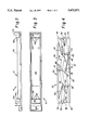
- FIG. 1 is a view, in perspective, of a typical corona charger, with portions removed or broken away to facilitate viewing;
- FIG. 2 is a side elevational view of the corona charger of FIG. 1;
- FIG. 4 is a top plan view of the corona wire handling device, according 16 this invention, for facilitating replacement of the corona wires for the corona charger of FIG. 1;
- FIG. 5 is side elevational view, on an enlarged scale, of a wire guide post for the corona wire handling device of FIG. 5;
- FIG. 6 is a top plan view of a corona charger and the corona wire handling device, according to this invention, in association for replacement of the corona wires;
- FIG. 7 is a top plan view of a corona charger and the corona wire handling device, according to this invention, after replacement of the corona wires and with excess portions of the handling device removed.
- FIGS. 1-3 show a typical corona charger, designated generally by the numeral 10.
- the corona charger 10 is utilized, for example, for the general purpose of uniformly charging a dielectric member surface in any well known electrostatographic reproduction apparatus or the like, although other suitable uses for the corona charger are contemplated.
- the corona charger 10 includes a housing shell 12 having a first end portion 12a and a second end portion 12b interconnected by an elongated central portion 12c.
- the housing shell 12 is formed, for example, from an insulative resin material molded in the desired shape as shown.
- At least one corona wire is supported to span the length of the central portion 12c of the housing shell. There may, of course, be multiple corona wires, or a single wire threaded back-and-forth to make multiple passes over the length of the central portion 12c.
- the corona wire handling device 30 includes a frame 32 formed for example from a single piece of suitable plastic, such as for example, polystyrene.
- the frame 32 which is preferably injection molded, is substantially rectangular so as to include opposing parallel, equal length long side members 34, and opposing parallel, equal length short side members 36 respectively connected to the long side members.
- the portions of the short side members 36, designated by the numerals 38, representing the areas of connection of the short side members 36 to the long side members 34, are substantially thinner, than the short side members themselves. This enables the short side members 36 to be readily selectively separable from the long side members 34 for the purpose more fully described below.
- the frame 32 also includes at least one member for supporting the intermediate portion of a corona wire 14 on the frame.
- the corona wire intermediate supporting member designated generally by the numeral 40, is substantially J-shaped.
- Each of the members 40 has a first leg portion 42 and an integral second leg portion 44.
- the first leg portion 42 which is relatively flexible in the direction perpendicular to the longitudinal axis of the leg portion, is connected to one of the long side members 34 and extends at an angle therefrom.
- the second leg portion 44 which is relatively rigid, is connected to the opposite long side member and extends at a substantial right angle thereto.
- connection of the first leg portion 42 to the long side member is substantially at the full size of the first leg portion, while the area 45 of, connection of the second leg portion to the respective long side member is substantially thinner than such side member so that the member 40 is readily selectively separable from the long side member for the purpose more fully described below.
- each of the guide posts 46 have a plurality of guide posts 46 extending respectively therefrom.
- the guide posts 46 serve to redirect a corona wire 14 supported thereon (as will be described in more detail below), and readily permit relative movement of the corona wire to the guide posts, in the direction along the longitudinal axis of the corona wire.
- each of the guide posts include a cap 46a.
- the caps 46a which may be formed for example by ultrasonically deforming the tops of the respective guide posts, serve to retain a corona wire in engagement with the posts.
- the caps 46a on the guide posts 46 which serve to capture the wire, can be replaced by other functional mechanisms (e.g., notches, hooks or the like) suitable for holding the wires to prevent their escape but permitting relative movement therebetween.
- Similar guide posts 48 which may also be capped, extend from the short side members 36.
- the opposing short side members 36 also respectively include a first stanchion 50 and a second stanchion 52 attached thereto.
- a single typical corona wire 14 is strung under tension in zigzag fashion from a first stanchion 50 to the second (final) stanchion 52, past the guide posts 46 and 48, under virtually no, or only a slight degree of, tension.
- the corona wire 14 may be stung manually, or by means of a suitable robotics device (not shown).
- the use of robotics in stringing the corona wire offers distinct advantages. That is, by substantially eliminating manual intervention (the wires are untouched by human hands), contamination of the wires is substantially reduced, as would also wire breakage, especially for very thin wires (e.g., on the order of 0.3 mils or less).
- Robotic stringing is especially useful for expensive noble metal corona wires or noble metal plated corona wires (such as gold-plated or platinum alloy wires) because such wires are generally very soft and easily scratched or damaged.
- the handling devices are readily packaged by any suitable robotic device for shipping. This will substantially reduce the danger of damage during packaging.
- the ability to handle each corona wire handling device 30, at all times, by the frame 32 substantially reduces the risk of corona wire contamination and/or breakage.
- the number and location of the guide posts 46 and 48 is dependent upon the geometrical configuration of the corona charger with which the frame 32 of the corona wire handling device 30 is to be associated. That is, the frame 32 may be readily modified to fit any desired corona charger shell design, including single or multi-wire chargers. For example, if more than one corona wire is to be used for corona chargers having one or any number of parallel longitudinal wires, there may be more than just the two stanchions 50, 52. Rather than using a single length of wire in a frame according to this invention, more than one wire can be used, each wire anchored to appropriate stanchions (which may be common stanchions).
- the frame 32 of the corona wire handling device 30 has particular connecting portions 38 and 45 which are much thinner than the remainder of the frame. These necked down portions enable the frame to be easily severed, such as by being cut with a tool or snapped apart manually, to separate the various members of the frame.
- the corona wire handling device 30 is employed to insert a corona wire 14 into the housing shell 12 of the corona charger 10, first the areas 45 are severed.
- the short side members 36 of the frame 32 are then aligned with the ends portions 12a and 12b of the charger housing shell 12 as shown in solid lines in FIG. 6.
- the short side members are then forced into the shell housing end portions 12a, 12b to initiate application of a desired tension to the corona wire by bending the flexible frame 32 over bridge walls 16a, 16b of the housing of the corona charger 10.
- the rims of the corona wire 14 Prior to applying the bending stress to the frame 32 of the corona wire handling device 30, the rims of the corona wire 14 are inserted into the notches 18 of the bridge walls 16a, 16b.
- the short side members 36 are retained near the floor of each of the housing portions 12a, 12b, located outboard of the walls 16a, 16b, such as by the anchor assembly 22 (see FIG. 1).
- the corona wire 14 tends to straighten out from its initial zigzag configuration between the bridge walls 16a, 16b.
- FIG. 1 As can be seen in the phantom lines of FIG.
- the straightening of the corona wire is accompanied by opening up the gaps produced by the previous separation of the legs 44 of the members 40 from the long side members 34 by the severing of portions 45.
- the reactive action of the members 40 serve to balance any tension build-up on the corona wire 14 during the process of insertion into the corona charger 10. That is, an appropriate degree of tension is maintained on the corona wire to enable proper insertion of the corona wire without breakage due to excessive tension.
- the guide posts 48 attached to the short side members 36 are not equidistantly spaced and are located in a way so as not to line up with the notches 18. This forces the runs of the corona wire 14 to bind at the edges of the notches 18 after the short side members 36 have been gripped in the anchor assembly 22. As such, the bind in the wire serves to help retard wire vibration during operation of the corona charger.
- equidistantly spaced guide posts, or guide posts aligned with the notches 18, can be used on the short side members 36.
- the thinned portions 38 connecting the short side members 36 with the long side members 34 are severed.
- the two long side members 34 of frame 32 which are then no longer connected to the short side members 36, are considered excess and can be removed and discarded (see FIG. 7).
- the J-shaped members 40, connected to the long side members 34, are of course also discarded with the long side members.
Abstract
Description
Claims (20)
Priority Applications (1)
| Application Number | Priority Date | Filing Date | Title |
|---|---|---|---|
| US08/609,073 US5672871A (en) | 1996-02-29 | 1996-02-29 | Corona wire handling device |
Applications Claiming Priority (1)
| Application Number | Priority Date | Filing Date | Title |
|---|---|---|---|
| US08/609,073 US5672871A (en) | 1996-02-29 | 1996-02-29 | Corona wire handling device |
Publications (1)
| Publication Number | Publication Date |
|---|---|
| US5672871A true US5672871A (en) | 1997-09-30 |
Family
ID=24439249
Family Applications (1)
| Application Number | Title | Priority Date | Filing Date |
|---|---|---|---|
| US08/609,073 Expired - Lifetime US5672871A (en) | 1996-02-29 | 1996-02-29 | Corona wire handling device |
Country Status (1)
| Country | Link |
|---|---|
| US (1) | US5672871A (en) |
Cited By (8)
| Publication number | Priority date | Publication date | Assignee | Title |
|---|---|---|---|---|
| US6098911A (en) * | 1999-03-08 | 2000-08-08 | Sheldon; Bradley | Portable filament dispenser |
| US6294782B1 (en) * | 1999-03-26 | 2001-09-25 | Nexpress Solutions Llc | Corona charger with a serpentine strung corona wire |
| US6298204B1 (en) | 1999-11-11 | 2001-10-02 | Nexpress Solutions Llc | Corona Charger with integral latch member for locating the charger relative to a roller |
| US6303933B1 (en) * | 1999-03-26 | 2001-10-16 | Nexpress Solutions Llc | Apparatus and method of attaching corona wire to corona charger housing |
| US6366753B1 (en) | 1999-11-11 | 2002-04-02 | Heidelberger Druckmaschinen Ag | Charger wire tensioning mounting mechanism and method of using |
| US6900436B1 (en) | 2000-10-14 | 2005-05-31 | Eastman Kodak Company | Corona wire tensioning mechanism |
| US20060176641A1 (en) * | 2003-06-11 | 2006-08-10 | Peter Gefter | Ionizing electrode structure and apparatus |
| US7339778B1 (en) * | 2003-06-11 | 2008-03-04 | Ion Systems | Corona discharge static neutralizing apparatus |
Citations (6)
| Publication number | Priority date | Publication date | Assignee | Title |
|---|---|---|---|---|
| US4764675A (en) * | 1987-10-22 | 1988-08-16 | Xerox Corporation | Self-tensioning coronode structure |
| US5074484A (en) * | 1990-06-27 | 1991-12-24 | Xerox Corporation | Corotron restringing tool |
| US5140367A (en) * | 1990-07-23 | 1992-08-18 | Station Eight, Inc. | Method and apparatus for rewiring corona wire cartridge |
| US5181069A (en) * | 1990-07-23 | 1993-01-19 | Station Eight, Inc. | Method and apparatus for rewiring corona wire cartridge |
| US5424540A (en) * | 1994-08-19 | 1995-06-13 | Eastman Kodak Company | Corona charger wire tensioning mechanism |
| US5449906A (en) * | 1994-01-03 | 1995-09-12 | Xerox Corporation | Corona generating electrode replacement tool |
-
1996
- 1996-02-29 US US08/609,073 patent/US5672871A/en not_active Expired - Lifetime
Patent Citations (6)
| Publication number | Priority date | Publication date | Assignee | Title |
|---|---|---|---|---|
| US4764675A (en) * | 1987-10-22 | 1988-08-16 | Xerox Corporation | Self-tensioning coronode structure |
| US5074484A (en) * | 1990-06-27 | 1991-12-24 | Xerox Corporation | Corotron restringing tool |
| US5140367A (en) * | 1990-07-23 | 1992-08-18 | Station Eight, Inc. | Method and apparatus for rewiring corona wire cartridge |
| US5181069A (en) * | 1990-07-23 | 1993-01-19 | Station Eight, Inc. | Method and apparatus for rewiring corona wire cartridge |
| US5449906A (en) * | 1994-01-03 | 1995-09-12 | Xerox Corporation | Corona generating electrode replacement tool |
| US5424540A (en) * | 1994-08-19 | 1995-06-13 | Eastman Kodak Company | Corona charger wire tensioning mechanism |
Cited By (9)
| Publication number | Priority date | Publication date | Assignee | Title |
|---|---|---|---|---|
| US6098911A (en) * | 1999-03-08 | 2000-08-08 | Sheldon; Bradley | Portable filament dispenser |
| US6294782B1 (en) * | 1999-03-26 | 2001-09-25 | Nexpress Solutions Llc | Corona charger with a serpentine strung corona wire |
| US6303933B1 (en) * | 1999-03-26 | 2001-10-16 | Nexpress Solutions Llc | Apparatus and method of attaching corona wire to corona charger housing |
| US6298204B1 (en) | 1999-11-11 | 2001-10-02 | Nexpress Solutions Llc | Corona Charger with integral latch member for locating the charger relative to a roller |
| US6366753B1 (en) | 1999-11-11 | 2002-04-02 | Heidelberger Druckmaschinen Ag | Charger wire tensioning mounting mechanism and method of using |
| US6900436B1 (en) | 2000-10-14 | 2005-05-31 | Eastman Kodak Company | Corona wire tensioning mechanism |
| US20060176641A1 (en) * | 2003-06-11 | 2006-08-10 | Peter Gefter | Ionizing electrode structure and apparatus |
| US7339778B1 (en) * | 2003-06-11 | 2008-03-04 | Ion Systems | Corona discharge static neutralizing apparatus |
| US7483255B2 (en) | 2003-06-11 | 2009-01-27 | Ion Systems | Ionizing electrode structure and apparatus |
Similar Documents
| Publication | Publication Date | Title |
|---|---|---|
| US5672871A (en) | Corona wire handling device | |
| US5424540A (en) | Corona charger wire tensioning mechanism | |
| EP0433621A2 (en) | Universal fastener | |
| DE69428922T2 (en) | Charging part, charging device and process cassette which can be removed from an image-forming device | |
| EP1365294A3 (en) | Developing apparatus | |
| US5449906A (en) | Corona generating electrode replacement tool | |
| EP0151865B1 (en) | Corona discharge device | |
| EP0465125B1 (en) | Corotron restringing tool | |
| JP3400269B2 (en) | Ball forming device in wire bonding | |
| US6303933B1 (en) | Apparatus and method of attaching corona wire to corona charger housing | |
| US3339069A (en) | Corona charging device with means to prevent toner dust contamination | |
| GB1596854A (en) | Corona generating device | |
| US4558613A (en) | Thermal wire stripper | |
| US5528808A (en) | Wire installation tool | |
| CA1232007A (en) | Corona generating device | |
| US4551784A (en) | Corona generating device | |
| US7208732B2 (en) | Structure for attaching wire assembly to a dicor housing | |
| JPH08323633A (en) | Sheet material grasping tool and image forming device with sheet material clamping tool | |
| JPS6290675A (en) | Transfer device for color copying machine | |
| US5303886A (en) | Method and apparatus for supporting an object from a channel | |
| JPS58196553A (en) | Corotron device of electrophotographic copying machine or the like | |
| JPH0438357Y2 (en) | ||
| JPS59126554A (en) | Corotron of copying machine | |
| CA2358630C (en) | Corona wire tensioning mechanism | |
| JP2003045610A (en) | Corona discharge wire, corona discharge apparatus having the corona discharge wire and securing method of corona discharge wire |
Legal Events
| Date | Code | Title | Description |
|---|---|---|---|
| AS | Assignment |
Owner name: EASTMAN KODAK COMPANY, NEW YORK Free format text: ASSIGNMENT OF ASSIGNORS INTEREST;ASSIGNORS:JACOBS, MICHAEL E.;MAY, JOHN W.;REEL/FRAME:007902/0034 Effective date: 19960229 |
|
| FEPP | Fee payment procedure |
Free format text: PAYOR NUMBER ASSIGNED (ORIGINAL EVENT CODE: ASPN); ENTITY STATUS OF PATENT OWNER: LARGE ENTITY |
|
| STCF | Information on status: patent grant |
Free format text: PATENTED CASE |
|
| FEPP | Fee payment procedure |
Free format text: PAYER NUMBER DE-ASSIGNED (ORIGINAL EVENT CODE: RMPN); ENTITY STATUS OF PATENT OWNER: LARGE ENTITY Free format text: PAYOR NUMBER ASSIGNED (ORIGINAL EVENT CODE: ASPN); ENTITY STATUS OF PATENT OWNER: LARGE ENTITY |
|
| FPAY | Fee payment |
Year of fee payment: 4 |
|
| AS | Assignment |
Owner name: NEXPRESS SOLUTIONS LLC, NEW YORK Free format text: ASSIGNMENT OF ASSIGNORS INTEREST;ASSIGNOR:EASTMAN KODAK COMPANY;REEL/FRAME:012036/0959 Effective date: 20000717 |
|
| AS | Assignment |
Owner name: EASTMAN KODAK COMPANY, NEW YORK Free format text: ASSIGNMENT OF ASSIGNORS INTEREST;ASSIGNOR:NEXPRESS SOLUTIONS, INC. (FORMERLY NEXPRESS SOLUTIONS LLC);REEL/FRAME:015928/0176 Effective date: 20040909 |
|
| FEPP | Fee payment procedure |
Free format text: PAYER NUMBER DE-ASSIGNED (ORIGINAL EVENT CODE: RMPN); ENTITY STATUS OF PATENT OWNER: LARGE ENTITY Free format text: PAYOR NUMBER ASSIGNED (ORIGINAL EVENT CODE: ASPN); ENTITY STATUS OF PATENT OWNER: LARGE ENTITY |
|
| FEPP | Fee payment procedure |
Free format text: PAYER NUMBER DE-ASSIGNED (ORIGINAL EVENT CODE: RMPN); ENTITY STATUS OF PATENT OWNER: LARGE ENTITY Free format text: PAYOR NUMBER ASSIGNED (ORIGINAL EVENT CODE: ASPN); ENTITY STATUS OF PATENT OWNER: LARGE ENTITY |
|
| FPAY | Fee payment |
Year of fee payment: 8 |
|
| FEPP | Fee payment procedure |
Free format text: PAYER NUMBER DE-ASSIGNED (ORIGINAL EVENT CODE: RMPN); ENTITY STATUS OF PATENT OWNER: LARGE ENTITY Free format text: PAYOR NUMBER ASSIGNED (ORIGINAL EVENT CODE: ASPN); ENTITY STATUS OF PATENT OWNER: LARGE ENTITY |
|
| FPAY | Fee payment |
Year of fee payment: 12 |
|
| AS | Assignment |
Owner name: CITICORP NORTH AMERICA, INC., AS AGENT, NEW YORK Free format text: SECURITY INTEREST;ASSIGNORS:EASTMAN KODAK COMPANY;PAKON, INC.;REEL/FRAME:028201/0420 Effective date: 20120215 |
|
| AS | Assignment |
Owner name: WILMINGTON TRUST, NATIONAL ASSOCIATION, AS AGENT, Free format text: PATENT SECURITY AGREEMENT;ASSIGNORS:EASTMAN KODAK COMPANY;PAKON, INC.;REEL/FRAME:030122/0235 Effective date: 20130322 Owner name: WILMINGTON TRUST, NATIONAL ASSOCIATION, AS AGENT, MINNESOTA Free format text: PATENT SECURITY AGREEMENT;ASSIGNORS:EASTMAN KODAK COMPANY;PAKON, INC.;REEL/FRAME:030122/0235 Effective date: 20130322 |
|
| AS | Assignment |
Owner name: BARCLAYS BANK PLC, AS ADMINISTRATIVE AGENT, NEW YORK Free format text: INTELLECTUAL PROPERTY SECURITY AGREEMENT (SECOND LIEN);ASSIGNORS:EASTMAN KODAK COMPANY;FAR EAST DEVELOPMENT LTD.;FPC INC.;AND OTHERS;REEL/FRAME:031159/0001 Effective date: 20130903 Owner name: JPMORGAN CHASE BANK, N.A., AS ADMINISTRATIVE, DELAWARE Free format text: INTELLECTUAL PROPERTY SECURITY AGREEMENT (FIRST LIEN);ASSIGNORS:EASTMAN KODAK COMPANY;FAR EAST DEVELOPMENT LTD.;FPC INC.;AND OTHERS;REEL/FRAME:031158/0001 Effective date: 20130903 Owner name: EASTMAN KODAK COMPANY, NEW YORK Free format text: RELEASE OF SECURITY INTEREST IN PATENTS;ASSIGNORS:CITICORP NORTH AMERICA, INC., AS SENIOR DIP AGENT;WILMINGTON TRUST, NATIONAL ASSOCIATION, AS JUNIOR DIP AGENT;REEL/FRAME:031157/0451 Effective date: 20130903 Owner name: JPMORGAN CHASE BANK, N.A., AS ADMINISTRATIVE, DELA Free format text: INTELLECTUAL PROPERTY SECURITY AGREEMENT (FIRST LIEN);ASSIGNORS:EASTMAN KODAK COMPANY;FAR EAST DEVELOPMENT LTD.;FPC INC.;AND OTHERS;REEL/FRAME:031158/0001 Effective date: 20130903 Owner name: PAKON, INC., NEW YORK Free format text: RELEASE OF SECURITY INTEREST IN PATENTS;ASSIGNORS:CITICORP NORTH AMERICA, INC., AS SENIOR DIP AGENT;WILMINGTON TRUST, NATIONAL ASSOCIATION, AS JUNIOR DIP AGENT;REEL/FRAME:031157/0451 Effective date: 20130903 Owner name: BARCLAYS BANK PLC, AS ADMINISTRATIVE AGENT, NEW YO Free format text: INTELLECTUAL PROPERTY SECURITY AGREEMENT (SECOND LIEN);ASSIGNORS:EASTMAN KODAK COMPANY;FAR EAST DEVELOPMENT LTD.;FPC INC.;AND OTHERS;REEL/FRAME:031159/0001 Effective date: 20130903 Owner name: BANK OF AMERICA N.A., AS AGENT, MASSACHUSETTS Free format text: INTELLECTUAL PROPERTY SECURITY AGREEMENT (ABL);ASSIGNORS:EASTMAN KODAK COMPANY;FAR EAST DEVELOPMENT LTD.;FPC INC.;AND OTHERS;REEL/FRAME:031162/0117 Effective date: 20130903 |
|
| AS | Assignment |
Owner name: EASTMAN KODAK COMPANY, NEW YORK Free format text: RELEASE BY SECURED PARTY;ASSIGNOR:BARCLAYS BANK PLC;REEL/FRAME:041656/0531 Effective date: 20170202 |
|
| AS | Assignment |
Owner name: KODAK AMERICAS, LTD., NEW YORK Free format text: RELEASE BY SECURED PARTY;ASSIGNOR:JP MORGAN CHASE BANK, N.A., AS ADMINISTRATIVE AGENT;REEL/FRAME:050239/0001 Effective date: 20190617 Owner name: KODAK (NEAR EAST), INC., NEW YORK Free format text: RELEASE BY SECURED PARTY;ASSIGNOR:JP MORGAN CHASE BANK, N.A., AS ADMINISTRATIVE AGENT;REEL/FRAME:050239/0001 Effective date: 20190617 Owner name: KODAK IMAGING NETWORK, INC., NEW YORK Free format text: RELEASE BY SECURED PARTY;ASSIGNOR:JP MORGAN CHASE BANK, N.A., AS ADMINISTRATIVE AGENT;REEL/FRAME:050239/0001 Effective date: 20190617 Owner name: LASER PACIFIC MEDIA CORPORATION, NEW YORK Free format text: RELEASE BY SECURED PARTY;ASSIGNOR:JP MORGAN CHASE BANK, N.A., AS ADMINISTRATIVE AGENT;REEL/FRAME:050239/0001 Effective date: 20190617 Owner name: FPC, INC., NEW YORK Free format text: RELEASE BY SECURED PARTY;ASSIGNOR:JP MORGAN CHASE BANK, N.A., AS ADMINISTRATIVE AGENT;REEL/FRAME:050239/0001 Effective date: 20190617 Owner name: KODAK PHILIPPINES, LTD., NEW YORK Free format text: RELEASE BY SECURED PARTY;ASSIGNOR:JP MORGAN CHASE BANK, N.A., AS ADMINISTRATIVE AGENT;REEL/FRAME:050239/0001 Effective date: 20190617 Owner name: NPEC, INC., NEW YORK Free format text: RELEASE BY SECURED PARTY;ASSIGNOR:JP MORGAN CHASE BANK, N.A., AS ADMINISTRATIVE AGENT;REEL/FRAME:050239/0001 Effective date: 20190617 Owner name: KODAK PORTUGUESA LIMITED, NEW YORK Free format text: RELEASE BY SECURED PARTY;ASSIGNOR:JP MORGAN CHASE BANK, N.A., AS ADMINISTRATIVE AGENT;REEL/FRAME:050239/0001 Effective date: 20190617 Owner name: PAKON, INC., NEW YORK Free format text: RELEASE BY SECURED PARTY;ASSIGNOR:JP MORGAN CHASE BANK, N.A., AS ADMINISTRATIVE AGENT;REEL/FRAME:050239/0001 Effective date: 20190617 Owner name: KODAK REALTY, INC., NEW YORK Free format text: RELEASE BY SECURED PARTY;ASSIGNOR:JP MORGAN CHASE BANK, N.A., AS ADMINISTRATIVE AGENT;REEL/FRAME:050239/0001 Effective date: 20190617 Owner name: EASTMAN KODAK COMPANY, NEW YORK Free format text: RELEASE BY SECURED PARTY;ASSIGNOR:JP MORGAN CHASE BANK, N.A., AS ADMINISTRATIVE AGENT;REEL/FRAME:050239/0001 Effective date: 20190617 Owner name: KODAK AVIATION LEASING LLC, NEW YORK Free format text: RELEASE BY SECURED PARTY;ASSIGNOR:JP MORGAN CHASE BANK, N.A., AS ADMINISTRATIVE AGENT;REEL/FRAME:050239/0001 Effective date: 20190617 Owner name: QUALEX, INC., NEW YORK Free format text: RELEASE BY SECURED PARTY;ASSIGNOR:JP MORGAN CHASE BANK, N.A., AS ADMINISTRATIVE AGENT;REEL/FRAME:050239/0001 Effective date: 20190617 Owner name: FAR EAST DEVELOPMENT LTD., NEW YORK Free format text: RELEASE BY SECURED PARTY;ASSIGNOR:JP MORGAN CHASE BANK, N.A., AS ADMINISTRATIVE AGENT;REEL/FRAME:050239/0001 Effective date: 20190617 Owner name: CREO MANUFACTURING AMERICA LLC, NEW YORK Free format text: RELEASE BY SECURED PARTY;ASSIGNOR:JP MORGAN CHASE BANK, N.A., AS ADMINISTRATIVE AGENT;REEL/FRAME:050239/0001 Effective date: 20190617 |
|
| AS | Assignment |
Owner name: KODAK AMERICAS, LTD., NEW YORK Free format text: RELEASE BY SECURED PARTY;ASSIGNOR:JP MORGAN CHASE BANK, N.A., AS ADMINISTRATIVE AGENT;REEL/FRAME:049901/0001 Effective date: 20190617 Owner name: EASTMAN KODAK COMPANY, NEW YORK Free format text: RELEASE BY SECURED PARTY;ASSIGNOR:JP MORGAN CHASE BANK, N.A., AS ADMINISTRATIVE AGENT;REEL/FRAME:049901/0001 Effective date: 20190617 Owner name: KODAK REALTY, INC., NEW YORK Free format text: RELEASE BY SECURED PARTY;ASSIGNOR:JP MORGAN CHASE BANK, N.A., AS ADMINISTRATIVE AGENT;REEL/FRAME:049901/0001 Effective date: 20190617 Owner name: LASER PACIFIC MEDIA CORPORATION, NEW YORK Free format text: RELEASE BY SECURED PARTY;ASSIGNOR:JP MORGAN CHASE BANK, N.A., AS ADMINISTRATIVE AGENT;REEL/FRAME:049901/0001 Effective date: 20190617 Owner name: PFC, INC., NEW YORK Free format text: RELEASE BY SECURED PARTY;ASSIGNOR:JP MORGAN CHASE BANK, N.A., AS ADMINISTRATIVE AGENT;REEL/FRAME:049901/0001 Effective date: 20190617 Owner name: QUALEX, INC., NEW YORK Free format text: RELEASE BY SECURED PARTY;ASSIGNOR:JP MORGAN CHASE BANK, N.A., AS ADMINISTRATIVE AGENT;REEL/FRAME:049901/0001 Effective date: 20190617 Owner name: KODAK (NEAR EAST), INC., NEW YORK Free format text: RELEASE BY SECURED PARTY;ASSIGNOR:JP MORGAN CHASE BANK, N.A., AS ADMINISTRATIVE AGENT;REEL/FRAME:049901/0001 Effective date: 20190617 Owner name: KODAK IMAGING NETWORK, INC., NEW YORK Free format text: RELEASE BY SECURED PARTY;ASSIGNOR:JP MORGAN CHASE BANK, N.A., AS ADMINISTRATIVE AGENT;REEL/FRAME:049901/0001 Effective date: 20190617 Owner name: FAR EAST DEVELOPMENT LTD., NEW YORK Free format text: RELEASE BY SECURED PARTY;ASSIGNOR:JP MORGAN CHASE BANK, N.A., AS ADMINISTRATIVE AGENT;REEL/FRAME:049901/0001 Effective date: 20190617 Owner name: KODAK PHILIPPINES, LTD., NEW YORK Free format text: RELEASE BY SECURED PARTY;ASSIGNOR:JP MORGAN CHASE BANK, N.A., AS ADMINISTRATIVE AGENT;REEL/FRAME:049901/0001 Effective date: 20190617 Owner name: PAKON, INC., NEW YORK Free format text: RELEASE BY SECURED PARTY;ASSIGNOR:JP MORGAN CHASE BANK, N.A., AS ADMINISTRATIVE AGENT;REEL/FRAME:049901/0001 Effective date: 20190617 Owner name: KODAK AVIATION LEASING LLC, NEW YORK Free format text: RELEASE BY SECURED PARTY;ASSIGNOR:JP MORGAN CHASE BANK, N.A., AS ADMINISTRATIVE AGENT;REEL/FRAME:049901/0001 Effective date: 20190617 Owner name: NPEC, INC., NEW YORK Free format text: RELEASE BY SECURED PARTY;ASSIGNOR:JP MORGAN CHASE BANK, N.A., AS ADMINISTRATIVE AGENT;REEL/FRAME:049901/0001 Effective date: 20190617 Owner name: KODAK PORTUGUESA LIMITED, NEW YORK Free format text: RELEASE BY SECURED PARTY;ASSIGNOR:JP MORGAN CHASE BANK, N.A., AS ADMINISTRATIVE AGENT;REEL/FRAME:049901/0001 Effective date: 20190617 Owner name: CREO MANUFACTURING AMERICA LLC, NEW YORK Free format text: RELEASE BY SECURED PARTY;ASSIGNOR:JP MORGAN CHASE BANK, N.A., AS ADMINISTRATIVE AGENT;REEL/FRAME:049901/0001 Effective date: 20190617 |
|
| AS | Assignment |
Owner name: NPEC INC., NEW YORK Free format text: RELEASE BY SECURED PARTY;ASSIGNOR:BARCLAYS BANK PLC;REEL/FRAME:052773/0001 Effective date: 20170202 Owner name: KODAK PHILIPPINES LTD., NEW YORK Free format text: RELEASE BY SECURED PARTY;ASSIGNOR:BARCLAYS BANK PLC;REEL/FRAME:052773/0001 Effective date: 20170202 Owner name: FPC INC., NEW YORK Free format text: RELEASE BY SECURED PARTY;ASSIGNOR:BARCLAYS BANK PLC;REEL/FRAME:052773/0001 Effective date: 20170202 Owner name: LASER PACIFIC MEDIA CORPORATION, NEW YORK Free format text: RELEASE BY SECURED PARTY;ASSIGNOR:BARCLAYS BANK PLC;REEL/FRAME:052773/0001 Effective date: 20170202 Owner name: KODAK (NEAR EAST) INC., NEW YORK Free format text: RELEASE BY SECURED PARTY;ASSIGNOR:BARCLAYS BANK PLC;REEL/FRAME:052773/0001 Effective date: 20170202 Owner name: EASTMAN KODAK COMPANY, NEW YORK Free format text: RELEASE BY SECURED PARTY;ASSIGNOR:BARCLAYS BANK PLC;REEL/FRAME:052773/0001 Effective date: 20170202 Owner name: FAR EAST DEVELOPMENT LTD., NEW YORK Free format text: RELEASE BY SECURED PARTY;ASSIGNOR:BARCLAYS BANK PLC;REEL/FRAME:052773/0001 Effective date: 20170202 Owner name: KODAK REALTY INC., NEW YORK Free format text: RELEASE BY SECURED PARTY;ASSIGNOR:BARCLAYS BANK PLC;REEL/FRAME:052773/0001 Effective date: 20170202 Owner name: KODAK AMERICAS LTD., NEW YORK Free format text: RELEASE BY SECURED PARTY;ASSIGNOR:BARCLAYS BANK PLC;REEL/FRAME:052773/0001 Effective date: 20170202 Owner name: QUALEX INC., NEW YORK Free format text: RELEASE BY SECURED PARTY;ASSIGNOR:BARCLAYS BANK PLC;REEL/FRAME:052773/0001 Effective date: 20170202 |