US5678609A - Aerial duct with ribbed liner - Google Patents
Aerial duct with ribbed liner Download PDFInfo
- Publication number
- US5678609A US5678609A US08/398,978 US39897895A US5678609A US 5678609 A US5678609 A US 5678609A US 39897895 A US39897895 A US 39897895A US 5678609 A US5678609 A US 5678609A
- Authority
- US
- United States
- Prior art keywords
- duct
- aerial
- recited
- ribs
- web
- Prior art date
- Legal status (The legal status is an assumption and is not a legal conclusion. Google has not performed a legal analysis and makes no representation as to the accuracy of the status listed.)
- Expired - Lifetime
Links
Images


Classifications
-
- F—MECHANICAL ENGINEERING; LIGHTING; HEATING; WEAPONS; BLASTING
- F16—ENGINEERING ELEMENTS AND UNITS; GENERAL MEASURES FOR PRODUCING AND MAINTAINING EFFECTIVE FUNCTIONING OF MACHINES OR INSTALLATIONS; THERMAL INSULATION IN GENERAL
- F16L—PIPES; JOINTS OR FITTINGS FOR PIPES; SUPPORTS FOR PIPES, CABLES OR PROTECTIVE TUBING; MEANS FOR THERMAL INSULATION IN GENERAL
- F16L11/00—Hoses, i.e. flexible pipes
- F16L11/04—Hoses, i.e. flexible pipes made of rubber or flexible plastics
- F16L11/12—Hoses, i.e. flexible pipes made of rubber or flexible plastics with arrangements for particular purposes, e.g. specially profiled, with protecting layer, heated, electrically conducting
- F16L11/121—Hoses, i.e. flexible pipes made of rubber or flexible plastics with arrangements for particular purposes, e.g. specially profiled, with protecting layer, heated, electrically conducting specially profiled cross sections
-
- F—MECHANICAL ENGINEERING; LIGHTING; HEATING; WEAPONS; BLASTING
- F16—ENGINEERING ELEMENTS AND UNITS; GENERAL MEASURES FOR PRODUCING AND MAINTAINING EFFECTIVE FUNCTIONING OF MACHINES OR INSTALLATIONS; THERMAL INSULATION IN GENERAL
- F16L—PIPES; JOINTS OR FITTINGS FOR PIPES; SUPPORTS FOR PIPES, CABLES OR PROTECTIVE TUBING; MEANS FOR THERMAL INSULATION IN GENERAL
- F16L11/00—Hoses, i.e. flexible pipes
- F16L11/22—Multi-channel hoses
-
- F—MECHANICAL ENGINEERING; LIGHTING; HEATING; WEAPONS; BLASTING
- F16—ENGINEERING ELEMENTS AND UNITS; GENERAL MEASURES FOR PRODUCING AND MAINTAINING EFFECTIVE FUNCTIONING OF MACHINES OR INSTALLATIONS; THERMAL INSULATION IN GENERAL
- F16L—PIPES; JOINTS OR FITTINGS FOR PIPES; SUPPORTS FOR PIPES, CABLES OR PROTECTIVE TUBING; MEANS FOR THERMAL INSULATION IN GENERAL
- F16L3/00—Supports for pipes, cables or protective tubing, e.g. hangers, holders, clamps, cleats, clips, brackets
- F16L3/26—Supports for pipes, cables or protective tubing, e.g. hangers, holders, clamps, cleats, clips, brackets specially adapted for supporting the pipes all along their length, e.g. pipe channels or ducts
-
- G—PHYSICS
- G02—OPTICS
- G02B—OPTICAL ELEMENTS, SYSTEMS OR APPARATUS
- G02B6/00—Light guides; Structural details of arrangements comprising light guides and other optical elements, e.g. couplings
- G02B6/44—Mechanical structures for providing tensile strength and external protection for fibres, e.g. optical transmission cables
- G02B6/4401—Optical cables
- G02B6/4415—Cables for special applications
- G02B6/4416—Heterogeneous cables
- G02B6/4422—Heterogeneous cables of the overhead type
-
- G—PHYSICS
- G02—OPTICS
- G02B—OPTICAL ELEMENTS, SYSTEMS OR APPARATUS
- G02B6/00—Light guides; Structural details of arrangements comprising light guides and other optical elements, e.g. couplings
- G02B6/44—Mechanical structures for providing tensile strength and external protection for fibres, e.g. optical transmission cables
- G02B6/4439—Auxiliary devices
- G02B6/4459—Ducts; Conduits; Hollow tubes for air blown fibres
-
- G—PHYSICS
- G02—OPTICS
- G02B—OPTICAL ELEMENTS, SYSTEMS OR APPARATUS
- G02B6/00—Light guides; Structural details of arrangements comprising light guides and other optical elements, e.g. couplings
- G02B6/46—Processes or apparatus adapted for installing or repairing optical fibres or optical cables
- G02B6/48—Overhead installation
- G02B6/483—Installation of aerial type
-
- H—ELECTRICITY
- H02—GENERATION; CONVERSION OR DISTRIBUTION OF ELECTRIC POWER
- H02G—INSTALLATION OF ELECTRIC CABLES OR LINES, OR OF COMBINED OPTICAL AND ELECTRIC CABLES OR LINES
- H02G15/00—Cable fittings
- H02G15/08—Cable junctions
- H02G15/18—Cable junctions protected by sleeves, e.g. for communication cable
- H02G15/182—Cable junctions protected by sleeves, e.g. for communication cable held in expanded condition in radial direction prior to installation
- H02G15/1826—Cable junctions protected by sleeves, e.g. for communication cable held in expanded condition in radial direction prior to installation on a removable hollow core, e.g. a tube
- H02G15/1833—Cable junctions protected by sleeves, e.g. for communication cable held in expanded condition in radial direction prior to installation on a removable hollow core, e.g. a tube formed of helically wound strip with adjacent windings, which are removable by applying a pulling force to a strip end
-
- H—ELECTRICITY
- H02—GENERATION; CONVERSION OR DISTRIBUTION OF ELECTRIC POWER
- H02G—INSTALLATION OF ELECTRIC CABLES OR LINES, OR OF COMBINED OPTICAL AND ELECTRIC CABLES OR LINES
- H02G7/00—Overhead installations of electric lines or cables
- H02G7/05—Suspension arrangements or devices for electric cables or lines
- H02G7/06—Suspensions for lines or cables along a separate supporting wire, e.g. S-hook
-
- B—PERFORMING OPERATIONS; TRANSPORTING
- B29—WORKING OF PLASTICS; WORKING OF SUBSTANCES IN A PLASTIC STATE IN GENERAL
- B29L—INDEXING SCHEME ASSOCIATED WITH SUBCLASS B29C, RELATING TO PARTICULAR ARTICLES
- B29L2023/00—Tubular articles
- B29L2023/003—Tubular articles having irregular or rough surfaces
-
- B—PERFORMING OPERATIONS; TRANSPORTING
- B29—WORKING OF PLASTICS; WORKING OF SUBSTANCES IN A PLASTIC STATE IN GENERAL
- B29L—INDEXING SCHEME ASSOCIATED WITH SUBCLASS B29C, RELATING TO PARTICULAR ARTICLES
- B29L2023/00—Tubular articles
- B29L2023/005—Hoses, i.e. flexible
Definitions
- This invention relates to ducts adapted to receive a cable and, more particularly to such ducts which have a support strand encased within a support duct that is connected to a second duct having a liner and being adapted to receive transmission cable.
- Aerial installations of transmission cables have been described in the art. Some aerially installed transmission cables have self-supporting capabilities incorporated into their design. However, transmission cables which do not possess the mechanical integrity to be self-supporting must either be lashed to a guide wire or inserted into a duct that is in turn lashed to a guide wire.
- the lashing process requires several steps which include stringing the guide wire between supports to a desired tautness; temporarily securing the transmission cable or duct containing the transmission cable to the guide wire; and permanently securing the transmission cable or duct to the guide wire with a lashing machine. These steps are time and labor intensive, and increase the expense of installation.
- One technique implemented to avoid the lashing process is permanently joining the guide wire to the transmission cable by placing the guide wire within the sheathing which surrounds and protects the transmission cable.
- the guide wire is joined within the sheathing in an offset manner so the guide wire can be independently manipulated relative to the transmission cable.
- the guide wire and transmission cable are aerially mounted, the guide wire is permanently fixed within the sheathing of the transmission cable, and the lashing process is eliminated.
- fiber optic transmission cables have the benefits of speed and capacity over copper cable, they possess mechanical characteristics which require careful handling. Fiber optic cables are fragile in nature and sensitive to the differing coefficients of thermal expansion between plastic, glass, and metal. Therefore, fiber optic cables do not easily lend themselves to having a guide wire permanently joined within the sheathing surrounding them without potentially damaging the fiber optic cable. Also, the fragility of fiber optic cable prevents it from being lashed to a guide wire without possible damage resulting. Consequently, an approach to aerially mounting fiber optic transmission cable which will allow damaged or obsolete transmission cable to be replaced in a reasonably practical and cost effective manner is needed.
- Fiber optic transmission cable is usually encased within a thermoplastic sheathing.
- a thermoplastic sheathing When installing or replacing a cable within a duct there are a number of problems that must be avoided.
- the plastic sheathing must not encounter any sharp surfaces that might damage or shave it away to any substantial degree. If the plastic sheathing is damaged in any way, detrimental exposure of the fragile optic transmission cable occurs.
- corrugated ducts when used alone in the standard process of burying ducted cable is very problematic.
- U.S. Pat. No. 5,087,153 disclosed that although corrugated duct, i.e. transverse ribs, have a lower coefficient of friction than smooth wall ducts, corrugated ducts have relatively thin and non-uniform wall thickness. Moreover, the thin walled corrugations have a tendency to stretch or break during field installation due to their relatively low tensile strength, and wear quickly when transmission cable is pulled therethrough.
- the flexible nature of corrugated tubing also allowed it to rotate and shear.
- corrugated ribs provide a very low coefficient of friction and the problems associated with its flexible nature can be overcome by using it as a liner contained within a separate distinct duct.
- Polyethylene duct products have historically been made out of high density polyethylene resins because their higher crystallinity imparts high strength, high modulus of elasticity, surface hardness and low friction. This higher hardness improves pulling performance significantly, and imbues the duct with toughness and resistance to ovalization and kinking.
- the high modulus of elasticity also resists premature elongation and stretching, which could otherwise damage the duct or compromise the diameter by either ovalizing or necking.
- the low surface friction of high density polyethylene (HDPE) makes it the material of choice when building a duct product.
- Thermal expansion is a significant problem. Unchecked, it can cause kinking of the duct at joints, corners or vertical transitions. Essentially anywhere that the duct is separated from the support strand expansion loads will begin to concentrate. HDPE expands 10 to 14 times as much as the steel strand, and may result in a difference in length of over 50 inches in a 300 ft. span of duct over a temperature drop of 120° F. to -20° F.
- Expansion and contraction of the duct surrounding the support strand can also cause problems in the long term survivability of the aerial duct.
- Continued cycles break down adhesive systems, and the continual rubbing can saw through this duct.
- Once the duct has been compromised a discontinuity forms.
- the expansion and contraction of the duct filling the discontinuity causes further accelerated destruction of the bond and jacket at the periphery of the discontinuity.
- Unattended, kinks or general unzipping of the duct from the strand can occur. Obviously this is a major problem since these duct systems would be commonly zigzagged across streets and highways
- the present invention comprises an aerial duct having multiple ducts for supporting optic transmission cable, and the like, comprising: a first duct; a support strand contained within said first duct, said support strand having a sufficient strength to hold the aerial duct suspended between pole supports; a second duct having an outside surface and an inside surface, said second duct being joined to said first duct; an inner duct contained within said second duct having an exterior surface and an interior surface; and a multiplicity of ribs formed along the length of the interior surface of said inner duct, said ribs having peaks of a predetermined height which are spaced apart a predetermined distance so that valleys are formed therebetween.
- the rib's valleys function to reduce contact between the cable and the duct surfaces and to store lubricant that facilitates the passage of an optic transmission cable through the second duct.
- the first duct and second duct are joined by an intervening web so that the first duct and second duct have substantially parallel longitudinal axes.
- the web is connected to the exterior surfaces of both the first and second duct.
- the web may also have a notch for controlled slitting.
- the first duct, the web, and the second duct comprise a jacket formed around the inner duct or liner and support strand.
- the inner duct or liner is preferably formed of a different material than that of the first and second duct, although this does not necessarily need to be the case.
- the inner duct or liner is formed from High Density Polyethylene (HDPE) to take advantage of the low coefficient of friction
- the first duct, web, and the second duct comprising the jacket are formed from a Linear Low Density Polyethylene (LLDPE) to take advantage of the lower modulus of elasticity.
- HDPE High Density Polyethylene
- LLDPE Linear Low Density Polyethylene
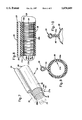
- FIG. 1 illustrates a first embodiment of the aerial duct being strung between two pole supports
- FIG. 2 is a partial perspective view of the aerial duct of FIG. 1 with the support strand and fiber optic cable shown in dashed lines;
- FIG. 3 is a partial longitudinal cross section of the aerial duct of FIG. 2;
- FIG. 4 is a partial expanded view of the internal spiral ribs of the aerial duct of FIG. 3;
- FIG. 5 is a partial perspective view of a second embodiment of the aerial duct having longitudinal ribs
- FIG. 6 is a transverse cross section of the aerial duct of FIG. 5;
- FIG. 7 is a partial perspective view of a preferred embodiment of the aerial duct having transverse ribs
- FIG. 8 is a partial longitudinal cross section of the aerial duct of FIG. 7;
- FIG. 9 is a transverse cross section of the aerial duct of FIG. 7.
- FIG. 10 is a transverse cross section of the web having a notch.
- FIG. 1 shows a truck 10 having a bed 12 upon which a spool 14 is rotatably support by spool support 16.
- a preferred embodiment of the ducted support strand or aerial duct 18 is wound around spool 14 for storage, transportation, an installation purposes.
- FIG. 1 shows the aerial duct 18 being strung between two pole supports 20.
- the ducted support strand or aerial duct 18 is connected to the pole supports 20 via mountings 22 in any conventional manner.
- the truck 10 moves ahead slowly so the aerial duct 18 can be unwound and connected to the next pole support.
- the technique of aerially mounting duct can be accomplished in any suitable manner.
- the fiber optic transmission cable 24 or other cable can be strung through a second duct 26 of the aerial duct 18, as best shown in FIG. 2.
- the aerial duct 18 includes a support or first duct 25 and a conduit or second duct 26.
- the first duct 25 includes a wall 23 having an outer surface 28 and an inner surface 30.
- a support strand 32 is encased within the first duct 25.
- the support strand 32 is used to secure the aerial duct 18 to the mountings 22 in any conventional manner and contributes to the overall strength and rigidity of the aerial duct 18.
- the support strand 32 is molded within the first duct 25 when the aerial duct 18 is extruded or otherwise manufactured. Alternately, the support strand 32 could be placed within the first duct 25 after the first duct is manufactured.
- the support strand 32 is made of extra strength Class C steel which is galvanized to reduce corrosion of any exposed areas but could alternatively be made of other suitable material known in the art.
- the support strand 32 is preferably a multistranded twisted strand for a large diameter aerial duct (ducts having a second duct inside diameter of one inch or greater).
- the multistranded twisted strand is a twisted multiple of seven strands of steel having a diameter of at least 0.25 inches and a tensile strength of at least 6600 pounds when the aerial duct 18 is connected between pole supports 20 spaced about 200 feet apart.
- a single strand of steel may be used for smaller aerial ducts.
- a single strand with a diameter of about 0.109 inches and a tensile strength of about 1200 pounds may be used with an aerial duct having an inner diameter of about 0.63 inches.
- multiply bundled twisted wires could be braided or twisted and inserted within the first duct 25, or; multiple support strands 32 can be linearly placed within the first duct 25 to further increase the rigidity and/or strength of the aerial duct 18. Multiple strands could further reduce rocking or rotation of the aerial duct 18 in high winds.
- the support strand 32 could alternatively be made of fiberglass, Kevlar, polyester, or other synthetic fibers such as a polyaramide composite, for example, when necessary to maintain the dielectric integrity of a fiber optic transmission system.
- the liner or inner duct 27 which has an exterior surface 54 and an interior surface 56.
- the exterior surface 54 abuts or lines the inside surface 38 of the second duct 26.
- the first duct 25 is joined to the second duct 26 by an intervening web 34.
- the web 34 is designed to provide adequate separation of the first duct 25 and the second duct 26 so that the first duct 25 can be properly clamped or otherwise secured to the pole supports 20.
- the web 34 is about 0.120 inches in width and about 0.250 inches in height for use with a second duct 26 having an inside diameter of about 1.520 inches and an outside diameter of about 1.660 inches.
- the stresses exerted by the second duct 26 can be absorbed, to a degree, by the web 34. This effect reduces the demands on the adhesive system at the strand and in turn improves the integrity of the duct system. Increased web height allows for the expansion stresses to be absorbed over the web, as opposed to transferring them directly to the strand.
- a molded narrowing or notch 60 may be formed in the web 34a in order to have a more controlled path for slitting and to make the web 34a more facile to cut.
- the notch 60 should be located nearer to the second duct 26, certainly no further than 1/2 half the length of the web 34a away from the second duct 26.
- the notch 60 located nearer to the second duct 26 prevents the shear stress that is expected if the notch 60 is located nearer to the first duct 25.
- the notch 60 extends no more than one half the way through the thickness of the web 34.
- the second duct 26 includes a wall 35 having an outside surface 36 and an inside surface 38.
- the interior surface 56 has spiral ribs 44 formed thereon which define peaks 40 and valleys 42 running the length of an inner duct or liner 27 encased within the second duct 26.
- the inner duct 27 has an outside diameter smaller than that of the inner diameter of second duct 26.
- the thickness of the liner 27 from peak 40 to exterior surface 54 is between 0.02 inches to about 0.25 inches.
- the problems with designing a self-supporting aerial duct system described above were addressed as follows.
- a jacketing process was developed, whereby the liner 27 is formed first, and a jacket 29 is formed over the liner 27 and the support strand secondly.
- the term "jacket" as used herein to describe the present invention refers to the first duct 25, the web 34, and the second duct 26. Because of this jacketing process, the materials used in the liner 27 relative to the jacket 29 can be selected from a wide variety of choices. Since HDPE is still the desired choice for low pulling friction, the liner 27 should remain HDPE. Alternatively, the liner 27 could be formed of PVC.
- the jacket 29, on the other hand can be comprised from a material which would be more flexible and stress relieving.
- LLDPE linear low density polyethylene
- the jacket 29 may also be formed of olefinic materials, such as olefinic elastomers.
- the ribs within the inner duct 27 may be either spiral 44, unidirectional or alternating (FIG. 2); longitudinal 46 (FIG. 5), or corrugated 48 (FIG. 7).
- the peaks 40, 40a, 40b of the ribs form a surface over which the fiber optic cable may pass at reduced friction.
- spiral 44 and corrugated 48 ribs have been found to give the best combination of results when used with a fiber optic cable 24 for reducing the friction between the cable 24 and the inner duct 27, providing structural integrity of the tubing, and not damaging the sheath on the cable 24.
- the spiral 44 and corrugated 48 ribs have the advantage in that the ribs do not shave off the sheathing because the cable tends to pass over them in a transverse manner.
- the internally spiraled duct is structurally strong and does not have a tendency to rip or tear during its installation. It is also flexible enough to go around corners if necessary. Also, the problems associated with the flexibility of the corrugated duct when used alone have been overcome by using the corrugated duct as an internal liner 27.
- the following embodiments include structural features such as the web 34 which are identical to those described above. For convenience, these features have been assigned the same reference numeral where appropriate.
- the web 34a shown in FIG. 10, having the notch 60 is interchangeable with the web 34, to thereby attain the benefits of the notch 60 discussed above.
- a second embodiment, shown in FIGS. 5 and 6, includes longitudinal ribs 46 formed by the liner 27a running the length of the second duct 26.
- the longitudinal ribs 46 also form peaks 40a and valleys or furrows 42a running the length of the liner 27a.
- the third embodiment illustrated in FIGS. 7-9, has corrugated ribs 48 along the length of the liner 27b forming peaks 40b and valleys 42b.
- the use of a corrugated duct as the liner 27b has many benefits associated with it. Because the liner 27b would be best comprised of HDPE, it would still be expected to expand and contract in a negative fashion as discussed above. Substituting a transversely corrugated liner 27b would allow the liner 27b to act as an accordion with regard to the expansion/contraction forces.
- corrugated liner 27b Another advantage of the corrugated liner 27b is low friction.
- the corrugated inner duct 27b offers one of the lowest friction configurations, since the contact area between the cable 24 and duct 27b are reduced to a series of points.
- the problem with corrugated ducts is that their inherent flexibility generally results in a less than straight installation, and the twists and undulations resulted in higher loads.
- the support strand 32 encased within the first duct 25 holds the aerial duct 18 in position, insuring a straight path.
- the corrugations contribute significant hoop or crush strength. This allows the combined wall thickness of the second duct 26 and the liner 27 to be reduced.
- the corrugations also function to lock the second duct 26. What results is an aerial duct 18 that has better flexibility and handling characteristics, has high crush strength and resistance to kinking, exhibits lower pulling friction, eliminates the need for expansion joints, has lower material cost, is easier for the lineman to install, and has the highest long term structural integrity.
- the liner 27, 27a, 27b respectfully, is essentially a stand-alone duct, around which a second duct 26 is placed.
- the jacket 29 around the liner 27 comprises the second duct 26, the first duct 25, and the web 34. These three are usually co-extruded. This allows considerable flexibility in adding features.
- Lubrication may be introduced, either as a surface spray to the interior surface 56, 56a, 56b respectfully, or in the compound throughout the body of the interior surface 56. In the latter case, the compounded lubricant migrates to the interior surface. Because there are discrete layers, separate colors for identification purposes can also be used.
- the manufacturing process may be a dual pass system which extrudes the liner 27 first, then passes the liner 27 through the line a second time to add self-supporting features such as metal or reinforcing fibers.
- This method also allows an armored duct to be formed by wrapping, longitudinally or spirally, a layer of metal or fiber-reinforced composite around the liner 27 prior to applying the jacket 29 and self-supporting features.
- the approach taken is a dual pass system, not coextrusion, however co-extrusion could be used if some of the options were limited.
- Both the support strand 32 and liner 27 can be glued to the jacket 29 with a flexible hot-melt adhesive. This is critical because of the thermal expansion and contraction characteristic of unreinforced plastics.
- the expansion stresses can be held back and dissipated though the web 34. This prevents a number of problems which would otherwise occur in aerial installation, such as: kinking of the aerial duct 18 and fiber optic cable 24 in corners due to expansion, pull-out of couplers due to contraction, saw-through of the support strand 32 though the jacket 29, etc.
- Putting the strand 32 in adhesive also acts to resist the penetration by water, which could induce corrosion of the strand 32, and result in damage to the first duct 25 due to expansion of ice.
- a glued liner construction is a means for incorporating damping into the composite design.
- the dual pass system also allows the creation of multiple duct combinations. This is very important because it is labor intensive to install support stranding and aerial ducts, but is generally very easy to pull cable into an aerial duct system.
- a multiple duct composite design requires the same equipment and effort to install as a single duct system, but offers the capacity of future modifications. Otherwise, additional cables would have to be lashed to the structure.
- An alternate configuration of the preferred embodiments described herein could include more than one inner duct in case it was necessary to keep various transmission cables separate from one another.
- the second duct's 26 inside diameter is not critical, although typically it ranges from 0.4 inch to about 2 inches.
- the inner duct's 27 inside diameter and wall thickness being slightly smaller so that it will fit in the second duct 26.
- Wall thickness may also vary, but common to this invention are sizes such as Standard Thermoplastic Pipe Dimension Ratio (SIDR) 5 through 21.
- SIDR Standard Thermoplastic Pipe Dimension Ratio
- the wall thickness of the first duct 25 and the second duct 26 preferably ranges from about 0.04 inches to about 0.2 inches.
- Rib height for spiral 44, longitudinal 46, and corrugated ribs 48 typically varies from about 0.005 inch to 0.250 inch from furrow to peak, with the preferred height for spiral 44, and longitudinal 46 ribs being about 0.020 inch, and the preferred height for corrugated ribs 48 being about 0.120 inch.
- Rib spacing for ribs typically varies between from about 0.025 inch and 0.500 inch, with the preferred spacing being about 0.125 inch for spiral 44, and longitudinal 46 ribs, and the preferred spacing for corrugated ribs 48 being about 0.300 inch.
- the frequency of spirals can range between 1.0 revolutions per foot and 0.05 revolution per foot, the preferred being about 0.33 revolution per foot, or one revolution every three feet.
- the direction of spiral rotation can be altered in a periodic fashion to create a sinusoidal wave, as well, without diminishing the improved effect.
- the second duct 26 of the preferred embodiments are substantially circular in cross section.
- the second duct 26 could alternatively be oval, triangular, rectangular, or other shapes in cross section if necessary.
- the exterior surface 54 of the corrugated inner duct 27b has apexes 51b and recess 52b which can be formed to be in contact with the interior surface 38b of the second duct 26 by coextrusion.
- the inner duct 27b is constructed first.
- a layer of metal or fiber reinforced composite (not shown) may be wrapped longitudinally or spirally around the inner duct 27b prior to applying the polymer jacket 29 which forms the second duct 26 the web 34, and the first duct 25. Besides the advantages of this wrapping to further reduce expansion and contraction, prior wrapping prevents the flexibilized polymer jacket that forms the first duct 25, the web 34, and the second duct 26 from entering the recesses 52b of the inner duct 27b.
- the metal or fiber reinforced composite may also function to protect the inner duct 27 from external damage. This damage is often caused by rodents such as squirrels, which are known to cause significant damage to aerial installations, or other forms of mechanical abuse such as gunshot damage.
- the inner duct 27 being made from a different material than the second duct 26, web 34, and first duct 25 has many desirable ramifications.
- High density and Linear Low Density Polyethylene have different physical characteristics discussed herein which heretofore have not been exploited for the formation of aerial ducts.
- the modulus of elasticity for HDPE is much greater than that of LLDPE. Therefore, LLDPE allows expansion of the polymer but does not cause too much stress. Under normal weather conditions, the modulus of elasticity for HDPE ranges from about 120,000 psi to about 200,000 psi and that of LLDPE ranges from about 20,000 psi to about 40,000 psi.
- HDPE could be used as the outer jacket (first duct 25, web 34, and second duct 26), and LLDPE as the interior liner or inner duct 27. As discussed above, the preferred embodiments have the outer jacket formed of LLDPE and the liner formed of HDPE.
- LLDPE low stress associated with LLDPE eliminates the need for expansion joints and allows for the aerial duct 18 to be attached at the poles which are spaced from 30 feet to about 300 feet.
- the LLDPE allows expansion, but does not produce a great deal of force.
- HDPE on the other hand has a desirable coefficient of friction in relationship to the optical fibers, and the corrugated ribs allow for a desired degree of flexibility, as well as expansion and contraction.
- LLDPE low density polyethylene
Landscapes
- Engineering & Computer Science (AREA)
- General Engineering & Computer Science (AREA)
- Physics & Mathematics (AREA)
- Mechanical Engineering (AREA)
- General Physics & Mathematics (AREA)
- Optics & Photonics (AREA)
- Rigid Pipes And Flexible Pipes (AREA)
Abstract
Description
Claims (38)
Priority Applications (1)
| Application Number | Priority Date | Filing Date | Title |
|---|---|---|---|
| US08/398,978 US5678609A (en) | 1995-03-06 | 1995-03-06 | Aerial duct with ribbed liner |
Applications Claiming Priority (1)
| Application Number | Priority Date | Filing Date | Title |
|---|---|---|---|
| US08/398,978 US5678609A (en) | 1995-03-06 | 1995-03-06 | Aerial duct with ribbed liner |
Publications (1)
| Publication Number | Publication Date |
|---|---|
| US5678609A true US5678609A (en) | 1997-10-21 |
Family
ID=23577605
Family Applications (1)
| Application Number | Title | Priority Date | Filing Date |
|---|---|---|---|
| US08/398,978 Expired - Lifetime US5678609A (en) | 1995-03-06 | 1995-03-06 | Aerial duct with ribbed liner |
Country Status (1)
| Country | Link |
|---|---|
| US (1) | US5678609A (en) |
Cited By (58)
| Publication number | Priority date | Publication date | Assignee | Title |
|---|---|---|---|---|
| US6135209A (en) * | 1998-10-01 | 2000-10-24 | Uhlenkott; William | Method for installing a water well pump |
| US6188821B1 (en) * | 1998-06-22 | 2001-02-13 | Siecor Operations, Llc | Apparatuses and methods for use in the making of a self-supporting fiber optic cable |
| US6344614B1 (en) * | 1997-10-27 | 2002-02-05 | Pirelli General Plc | Limiting electrical degradation of all-dielectric self supporting cables |
| US6548004B2 (en) * | 1996-05-09 | 2003-04-15 | Werner Born | Process for manufacturing individual pipe sections of a pipe system, and pipe system manufactured in said manner |
| US20030102043A1 (en) * | 2001-11-30 | 2003-06-05 | Field Larry W. | High density fiber optic cable inner ducts |
| WO2003085304A2 (en) * | 2002-03-29 | 2003-10-16 | Tvc Communications, L.L.C. | Multi-compartment aerial duct |
| US6695012B1 (en) * | 1999-10-12 | 2004-02-24 | Shell Oil Company | Lubricant coating for expandable tubular members |
| US6725919B2 (en) | 1998-12-07 | 2004-04-27 | Shell Oil Company | Forming a wellbore casing while simultaneously drilling a wellbore |
| US20040165957A1 (en) * | 1998-05-06 | 2004-08-26 | Serrano Jorge R. | Fiber optic installation structures in a paved surface, ducts, and methods therefor |
| US6796547B1 (en) | 2002-02-20 | 2004-09-28 | Arnco Corporation | Collapsible duct |
| US20040226623A1 (en) * | 1999-10-12 | 2004-11-18 | Oem/Miller, A Division Of Holm Industries | Dual wall co-extruded corrugated tubing |
| US20040232286A1 (en) * | 2003-03-18 | 2004-11-25 | Newkirk David C. | Patient line management system |
| US6823937B1 (en) | 1998-12-07 | 2004-11-30 | Shell Oil Company | Wellhead |
| US20050011570A1 (en) * | 2003-06-30 | 2005-01-20 | Rolls Royce Plc | Hose assembly |
| US20050072884A1 (en) * | 2001-07-17 | 2005-04-07 | Rivera Alexander F. | Single-handed cord/cable management device |
| US20050091826A1 (en) * | 2003-11-04 | 2005-05-05 | Fonville Carl E. | Expendable torque converter alignment ring and assembly method |
| US20060086016A1 (en) * | 2004-08-27 | 2006-04-27 | Anthony Cornell | Device for fixing lines |
| US7044218B2 (en) * | 1998-12-07 | 2006-05-16 | Shell Oil Company | Apparatus for radially expanding tubular members |
| US20060138286A1 (en) * | 2004-12-29 | 2006-06-29 | Connolly Michael J | Pipe hanger assembly |
| US20070026179A1 (en) * | 2005-07-26 | 2007-02-01 | Jan De Boer | PVC tube provided with a friction-reducing layer and method for the production thereof |
| US7182104B2 (en) | 2002-02-20 | 2007-02-27 | Arnco Corporation | Collapsible duct |
| US20070201799A1 (en) * | 2006-02-28 | 2007-08-30 | Conrad Craig M | Fiber optic cables having a toning lobe |
| US20080073106A1 (en) * | 2006-09-25 | 2008-03-27 | Commscope Solutions Properties Llc | Twisted pairs cable having shielding layer and dual jacket |
| US20080099226A1 (en) * | 2006-10-25 | 2008-05-01 | Goch Waymon P | Messenger supported overhead cable for electrical transmission |
| US20080121410A1 (en) * | 2006-06-20 | 2008-05-29 | Mccall Thomas Richard | Main duct with inner duct and method for producing the same |
| US20080128041A1 (en) * | 2006-12-04 | 2008-06-05 | The Lamson & Sessions Co. | Duct having silicone inner striping and composition for lubricious stripe coating |
| US7389961B1 (en) * | 2006-11-15 | 2008-06-24 | Floyd Haws | Hose outlet support bracket |
| US7447414B1 (en) * | 2006-06-19 | 2008-11-04 | Wayne Camick | Cable protector apparatus |
| US20090142138A1 (en) * | 2005-06-27 | 2009-06-04 | Saipem Uk Limited | Pipe Structure and Methods of Laying and Use of a Pipeline Including Such a Pipe Structure |
| US7578486B1 (en) | 2000-05-22 | 2009-08-25 | Jim Taylor | Drip hose hanger |
| ES2325942A1 (en) * | 2007-11-08 | 2009-09-24 | Nordix S.A. | Subscriber cable for optical fiber connections with dielectric autosoporte (Machine-translation by Google Translate, not legally binding) |
| US20090288727A1 (en) * | 2008-05-22 | 2009-11-26 | Lars-Ingvar Nordstrom | Tube of fabric reinforced pvc |
| US7665532B2 (en) | 1998-12-07 | 2010-02-23 | Shell Oil Company | Pipeline |
| US7712522B2 (en) | 2003-09-05 | 2010-05-11 | Enventure Global Technology, Llc | Expansion cone and system |
| US7740076B2 (en) | 2002-04-12 | 2010-06-22 | Enventure Global Technology, L.L.C. | Protective sleeve for threaded connections for expandable liner hanger |
| US7739917B2 (en) | 2002-09-20 | 2010-06-22 | Enventure Global Technology, Llc | Pipe formability evaluation for expandable tubulars |
| US7775290B2 (en) | 2003-04-17 | 2010-08-17 | Enventure Global Technology, Llc | Apparatus for radially expanding and plastically deforming a tubular member |
| US7793721B2 (en) | 2003-03-11 | 2010-09-14 | Eventure Global Technology, Llc | Apparatus for radially expanding and plastically deforming a tubular member |
| US20100247052A1 (en) * | 2009-03-27 | 2010-09-30 | 3M Innovative Properties Company | Low profile fiber drop point of entry system and method of installing |
| US20100243096A1 (en) * | 2009-03-27 | 2010-09-30 | 3M Innovative Properties Company | Ducts to support a drop access location system for horizontal cabling in multi-dwelling unit applications |
| US7819185B2 (en) | 2004-08-13 | 2010-10-26 | Enventure Global Technology, Llc | Expandable tubular |
| US20110030832A1 (en) * | 2009-08-06 | 2011-02-10 | 3M Innovative Properties Company | Adhesive backed ducts for cabling applications |
| US7886831B2 (en) | 2003-01-22 | 2011-02-15 | Enventure Global Technology, L.L.C. | Apparatus for radially expanding and plastically deforming a tubular member |
| US7918284B2 (en) | 2002-04-15 | 2011-04-05 | Enventure Global Technology, L.L.C. | Protective sleeve for threaded connections for expandable liner hanger |
| US20110078965A1 (en) * | 2009-08-18 | 2011-04-07 | Terry Umlor | Continuous heat welded flexible pvc membrane with an interlocking vapor barrier system |
| US8360127B2 (en) | 2008-06-25 | 2013-01-29 | 3M Innovative Properties Company | System for installing horizontal cabling in multi-dwelling units |
| US20140020783A1 (en) * | 2012-07-17 | 2014-01-23 | Chevron U.S.A. Inc. | Method and Apparatus for Reducing Fluid Flow Friction in a Pipe |
| WO2015088896A1 (en) * | 2013-12-09 | 2015-06-18 | Wagner Spray Tech Corporation | Collapsible hose for a painting system |
| USD745243S1 (en) * | 2013-02-07 | 2015-12-15 | Nisshin Foods Inc. | Macaroni |
| US9640958B2 (en) | 2010-04-14 | 2017-05-02 | 3M Innovative Properties Company | Removable adhesive backed ducts for cabling and a removal method |
| JP2017096427A (en) * | 2015-11-25 | 2017-06-01 | 株式会社カテックス | Multiple string parts, branch forming device and process of manufacture |
| EP3214473A1 (en) * | 2016-03-02 | 2017-09-06 | ING3 Beteiligungs GmbH | Support structure for an optical fiber cable |
| US9855696B2 (en) | 2013-11-25 | 2018-01-02 | Commscope, Inc. Of North Carolina | Aerial integrated messenger conduit |
| WO2018144529A1 (en) | 2017-02-01 | 2018-08-09 | Commscope Technologies Llc | Low friction indoor/outdoor optic fiber cable with fluted outer shape |
| US20190032837A1 (en) * | 2016-03-31 | 2019-01-31 | Alfred Kärcher SE & Co. KG | Fluid hose stabilizing device, fluid hose and cleaning apparatus |
| JP2019207373A (en) * | 2018-05-30 | 2019-12-05 | 住友電気工業株式会社 | Optical fiber cable |
| US20200055469A1 (en) * | 2017-03-30 | 2020-02-20 | Autonetworks Technologies, Ltd. | Path regulating member, clamp, and wire harness |
| US11355262B2 (en) * | 2002-09-24 | 2022-06-07 | Commscope Technologies Llc | Communication wire |
Citations (26)
| Publication number | Priority date | Publication date | Assignee | Title |
|---|---|---|---|---|
| US960291A (en) * | 1908-12-01 | 1910-06-07 | Carl Emil Egner | Aerial electric cable. |
| GB398627A (en) * | 1931-07-22 | 1933-09-21 | Lynenwerk Ges Mit Beschraenkte | Improvements in or relating to aerial electric cables with carrying devices |
| US2956311A (en) * | 1956-06-26 | 1960-10-18 | Osnabrucker Kupfer Und Drahtwe | Method of forming a suspension-type electric transmission cable |
| DE1106381B (en) * | 1960-06-08 | 1961-05-10 | Chem Fab Dr Franz & Rutenbeck | Self-supporting insulated electrical line or self-supporting cable |
| US3207836A (en) * | 1961-12-29 | 1965-09-21 | Western Electric Co | Self-supporting cable |
| US3267201A (en) * | 1963-10-04 | 1966-08-16 | Superior Cable Corp | Bonded messenger cable with messenger adhesively bonded to a common support jacket |
| US3532783A (en) * | 1968-02-28 | 1970-10-06 | Superior Continental Corp | Method of molding bonded messenger cable |
| US3540203A (en) * | 1965-04-27 | 1970-11-17 | Int Standard Electric Corp | Self-supporting cables with fine grained powder between support strands and extruded jacket and method of manufacture |
| US3720235A (en) * | 1970-09-30 | 1973-03-13 | Moore & Co Samuel | Composite tubing |
| CA1024228A (en) * | 1975-07-11 | 1978-01-10 | Friedrich K. Levacher | Electric cables with tension-supporting elements |
| US4160872A (en) * | 1976-08-24 | 1979-07-10 | Telefonaktiebolaget L M Ericsson | Self-floating cable for marine operations |
| JPS55150502A (en) * | 1979-05-14 | 1980-11-22 | Nippon Telegraph & Telephone | Selffsupport cable |
| US4378462A (en) * | 1980-08-01 | 1983-03-29 | Western Electric Company, Inc. | Self-supporting aerial cable and method of making same |
| US4410476A (en) * | 1980-10-20 | 1983-10-18 | The United States Of America As Represented By The Secretary Of The Navy | Method for making radially compliant line array hose |
| US4565351A (en) * | 1984-06-28 | 1986-01-21 | Arnco Corporation | Method for installing cable using an inner duct |
| GB2169094A (en) * | 1984-12-19 | 1986-07-02 | Telephone Cables Ltd | Optical cables |
| US4650715A (en) * | 1979-09-18 | 1987-03-17 | Kupferdraht-Isolierwerk Ag Wildegg | Element for transmission of tractive forces |
| US4662712A (en) * | 1982-12-18 | 1987-05-05 | Tohoku Electric Power Co., Inc. | Non-metallic self-supporting aerial optical cable |
| US4791965A (en) * | 1987-02-13 | 1988-12-20 | James Hardie Irrigation, Inc. | Co-extruded tube |
| US5073682A (en) * | 1990-08-09 | 1991-12-17 | Northern Telecom Limited | Telecommunications cable |
| US5087153A (en) * | 1989-08-23 | 1992-02-11 | Arnco Corporation | Internally spiraled duct and method of installation |
| US5089074A (en) * | 1989-09-11 | 1992-02-18 | Dayco Products, Inc. | Flexible hose construction and method of making the same |
| US5145545A (en) * | 1989-09-11 | 1992-09-08 | Dayco Products, Inc. | Flexible hose construction and method of making the same |
| GB2258711A (en) * | 1991-08-16 | 1993-02-17 | Integral Corp | Empty conduit assembly with detachable cable |
| US5238328A (en) * | 1992-01-23 | 1993-08-24 | Adams Robert M | System for coextruded innerduct with filled outer layer |
| US5256233A (en) * | 1989-09-11 | 1993-10-26 | Dayco Products, Inc. | Flexible hose construction and method of making the same |
-
1995
- 1995-03-06 US US08/398,978 patent/US5678609A/en not_active Expired - Lifetime
Patent Citations (28)
| Publication number | Priority date | Publication date | Assignee | Title |
|---|---|---|---|---|
| US960291A (en) * | 1908-12-01 | 1910-06-07 | Carl Emil Egner | Aerial electric cable. |
| GB398627A (en) * | 1931-07-22 | 1933-09-21 | Lynenwerk Ges Mit Beschraenkte | Improvements in or relating to aerial electric cables with carrying devices |
| US2956311A (en) * | 1956-06-26 | 1960-10-18 | Osnabrucker Kupfer Und Drahtwe | Method of forming a suspension-type electric transmission cable |
| DE1106381B (en) * | 1960-06-08 | 1961-05-10 | Chem Fab Dr Franz & Rutenbeck | Self-supporting insulated electrical line or self-supporting cable |
| US3207836A (en) * | 1961-12-29 | 1965-09-21 | Western Electric Co | Self-supporting cable |
| US3267201A (en) * | 1963-10-04 | 1966-08-16 | Superior Cable Corp | Bonded messenger cable with messenger adhesively bonded to a common support jacket |
| US3540203A (en) * | 1965-04-27 | 1970-11-17 | Int Standard Electric Corp | Self-supporting cables with fine grained powder between support strands and extruded jacket and method of manufacture |
| US3532783A (en) * | 1968-02-28 | 1970-10-06 | Superior Continental Corp | Method of molding bonded messenger cable |
| US3720235A (en) * | 1970-09-30 | 1973-03-13 | Moore & Co Samuel | Composite tubing |
| CA1024228A (en) * | 1975-07-11 | 1978-01-10 | Friedrich K. Levacher | Electric cables with tension-supporting elements |
| US4160872A (en) * | 1976-08-24 | 1979-07-10 | Telefonaktiebolaget L M Ericsson | Self-floating cable for marine operations |
| JPS55150502A (en) * | 1979-05-14 | 1980-11-22 | Nippon Telegraph & Telephone | Selffsupport cable |
| US4650715A (en) * | 1979-09-18 | 1987-03-17 | Kupferdraht-Isolierwerk Ag Wildegg | Element for transmission of tractive forces |
| US4378462A (en) * | 1980-08-01 | 1983-03-29 | Western Electric Company, Inc. | Self-supporting aerial cable and method of making same |
| US4410476A (en) * | 1980-10-20 | 1983-10-18 | The United States Of America As Represented By The Secretary Of The Navy | Method for making radially compliant line array hose |
| US4662712A (en) * | 1982-12-18 | 1987-05-05 | Tohoku Electric Power Co., Inc. | Non-metallic self-supporting aerial optical cable |
| US4565351A (en) * | 1984-06-28 | 1986-01-21 | Arnco Corporation | Method for installing cable using an inner duct |
| US4565351B1 (en) * | 1984-06-28 | 1992-12-01 | Arnco Corp | |
| GB2169094A (en) * | 1984-12-19 | 1986-07-02 | Telephone Cables Ltd | Optical cables |
| US4791965A (en) * | 1987-02-13 | 1988-12-20 | James Hardie Irrigation, Inc. | Co-extruded tube |
| US5087153A (en) * | 1989-08-23 | 1992-02-11 | Arnco Corporation | Internally spiraled duct and method of installation |
| US5087153B1 (en) * | 1989-08-23 | 1994-01-18 | Arnco Corporation | |
| US5089074A (en) * | 1989-09-11 | 1992-02-18 | Dayco Products, Inc. | Flexible hose construction and method of making the same |
| US5145545A (en) * | 1989-09-11 | 1992-09-08 | Dayco Products, Inc. | Flexible hose construction and method of making the same |
| US5256233A (en) * | 1989-09-11 | 1993-10-26 | Dayco Products, Inc. | Flexible hose construction and method of making the same |
| US5073682A (en) * | 1990-08-09 | 1991-12-17 | Northern Telecom Limited | Telecommunications cable |
| GB2258711A (en) * | 1991-08-16 | 1993-02-17 | Integral Corp | Empty conduit assembly with detachable cable |
| US5238328A (en) * | 1992-01-23 | 1993-08-24 | Adams Robert M | System for coextruded innerduct with filled outer layer |
Cited By (98)
| Publication number | Priority date | Publication date | Assignee | Title |
|---|---|---|---|---|
| US6548004B2 (en) * | 1996-05-09 | 2003-04-15 | Werner Born | Process for manufacturing individual pipe sections of a pipe system, and pipe system manufactured in said manner |
| US6344614B1 (en) * | 1997-10-27 | 2002-02-05 | Pirelli General Plc | Limiting electrical degradation of all-dielectric self supporting cables |
| US7351009B2 (en) * | 1998-05-06 | 2008-04-01 | Corning Cable Systems Llc | Fiber optic installation structures in a paved surface, ducts, and methods therefor |
| US20040165957A1 (en) * | 1998-05-06 | 2004-08-26 | Serrano Jorge R. | Fiber optic installation structures in a paved surface, ducts, and methods therefor |
| US6188821B1 (en) * | 1998-06-22 | 2001-02-13 | Siecor Operations, Llc | Apparatuses and methods for use in the making of a self-supporting fiber optic cable |
| US6135209A (en) * | 1998-10-01 | 2000-10-24 | Uhlenkott; William | Method for installing a water well pump |
| US6513597B2 (en) | 1998-10-01 | 2003-02-04 | William Uhlenkott | Method for installing a water well pump |
| US6302213B1 (en) * | 1998-10-01 | 2001-10-16 | William Uhlenkott | Method for installing a water well pump |
| US6668934B2 (en) | 1998-10-01 | 2003-12-30 | William Uhlenkott | Method for installing a water well pump |
| US20060065405A1 (en) * | 1998-10-01 | 2006-03-30 | William Uhlenkott | Method for installing a water well pump |
| US6988555B2 (en) * | 1998-10-01 | 2006-01-24 | William Uhlenkott | Method for installing a water well pump |
| US20050039924A1 (en) * | 1998-10-01 | 2005-02-24 | William Uhlenkott | Method for installing a water well pump |
| US6834716B2 (en) | 1998-10-01 | 2004-12-28 | William Uhlenkott | Water well including a pump |
| US6758278B2 (en) | 1998-12-07 | 2004-07-06 | Shell Oil Company | Forming a wellbore casing while simultaneously drilling a wellbore |
| US7044218B2 (en) * | 1998-12-07 | 2006-05-16 | Shell Oil Company | Apparatus for radially expanding tubular members |
| US7665532B2 (en) | 1998-12-07 | 2010-02-23 | Shell Oil Company | Pipeline |
| US6725919B2 (en) | 1998-12-07 | 2004-04-27 | Shell Oil Company | Forming a wellbore casing while simultaneously drilling a wellbore |
| US6739392B2 (en) | 1998-12-07 | 2004-05-25 | Shell Oil Company | Forming a wellbore casing while simultaneously drilling a wellbore |
| US6823937B1 (en) | 1998-12-07 | 2004-11-30 | Shell Oil Company | Wellhead |
| US20040226623A1 (en) * | 1999-10-12 | 2004-11-18 | Oem/Miller, A Division Of Holm Industries | Dual wall co-extruded corrugated tubing |
| US20060225803A1 (en) * | 1999-10-12 | 2006-10-12 | Chenoweth Kenneth R | Dual wall co-extruded corrugated tubing |
| US6695012B1 (en) * | 1999-10-12 | 2004-02-24 | Shell Oil Company | Lubricant coating for expandable tubular members |
| US7578486B1 (en) | 2000-05-22 | 2009-08-25 | Jim Taylor | Drip hose hanger |
| US20050072884A1 (en) * | 2001-07-17 | 2005-04-07 | Rivera Alexander F. | Single-handed cord/cable management device |
| US7077363B2 (en) * | 2001-07-17 | 2006-07-18 | Alexander F. Rivera | Single-handed cord/cable management device |
| US20030102043A1 (en) * | 2001-11-30 | 2003-06-05 | Field Larry W. | High density fiber optic cable inner ducts |
| US6845789B2 (en) | 2001-11-30 | 2005-01-25 | Corning Cable Systems Llc | High density fiber optic cable inner ducts |
| US20070130760A1 (en) * | 2002-02-20 | 2007-06-14 | Arnco Corporation | Collapsible duct |
| US6796547B1 (en) | 2002-02-20 | 2004-09-28 | Arnco Corporation | Collapsible duct |
| US7182104B2 (en) | 2002-02-20 | 2007-02-27 | Arnco Corporation | Collapsible duct |
| WO2003085304A2 (en) * | 2002-03-29 | 2003-10-16 | Tvc Communications, L.L.C. | Multi-compartment aerial duct |
| WO2003085304A3 (en) * | 2002-03-29 | 2004-01-08 | Marc Talon Inc | Multi-compartment aerial duct |
| US20050139279A1 (en) * | 2002-03-29 | 2005-06-30 | Allen Jerry L. | Multi-compartment aerial duct |
| US6886601B2 (en) * | 2002-03-29 | 2005-05-03 | Tvc Communications, L.L.C. | Multi-compartment aerial duct |
| US7740076B2 (en) | 2002-04-12 | 2010-06-22 | Enventure Global Technology, L.L.C. | Protective sleeve for threaded connections for expandable liner hanger |
| US7918284B2 (en) | 2002-04-15 | 2011-04-05 | Enventure Global Technology, L.L.C. | Protective sleeve for threaded connections for expandable liner hanger |
| US7739917B2 (en) | 2002-09-20 | 2010-06-22 | Enventure Global Technology, Llc | Pipe formability evaluation for expandable tubulars |
| US11355262B2 (en) * | 2002-09-24 | 2022-06-07 | Commscope Technologies Llc | Communication wire |
| US7886831B2 (en) | 2003-01-22 | 2011-02-15 | Enventure Global Technology, L.L.C. | Apparatus for radially expanding and plastically deforming a tubular member |
| US7793721B2 (en) | 2003-03-11 | 2010-09-14 | Eventure Global Technology, Llc | Apparatus for radially expanding and plastically deforming a tubular member |
| US7083150B2 (en) * | 2003-03-18 | 2006-08-01 | Hill-Rom Services, Inc. | Patient line management system |
| US20040232286A1 (en) * | 2003-03-18 | 2004-11-25 | Newkirk David C. | Patient line management system |
| US7775290B2 (en) | 2003-04-17 | 2010-08-17 | Enventure Global Technology, Llc | Apparatus for radially expanding and plastically deforming a tubular member |
| US7316246B2 (en) * | 2003-06-30 | 2008-01-08 | Rolls-Royce, Plc. | Hose assembly |
| US20050011570A1 (en) * | 2003-06-30 | 2005-01-20 | Rolls Royce Plc | Hose assembly |
| US7712522B2 (en) | 2003-09-05 | 2010-05-11 | Enventure Global Technology, Llc | Expansion cone and system |
| US20050091826A1 (en) * | 2003-11-04 | 2005-05-05 | Fonville Carl E. | Expendable torque converter alignment ring and assembly method |
| US7103957B2 (en) * | 2003-11-04 | 2006-09-12 | General Motors Corporation | Expendable torque converter alignment ring and assembly method |
| US7819185B2 (en) | 2004-08-13 | 2010-10-26 | Enventure Global Technology, Llc | Expandable tubular |
| US20060086016A1 (en) * | 2004-08-27 | 2006-04-27 | Anthony Cornell | Device for fixing lines |
| US7284728B2 (en) * | 2004-12-29 | 2007-10-23 | Connolly Michael J | Pipe hanger assembly |
| US20060138286A1 (en) * | 2004-12-29 | 2006-06-29 | Connolly Michael J | Pipe hanger assembly |
| AU2006263760B2 (en) * | 2005-06-27 | 2011-03-31 | Saipem Limited | Pipe structure and methods of laying and use of a pipeline including such a pipe structure |
| US8398336B2 (en) * | 2005-06-27 | 2013-03-19 | Saipem Uk Limited | Pipe structure and methods of laying and use of a pipeline including such a pipe structure |
| US20090142138A1 (en) * | 2005-06-27 | 2009-06-04 | Saipem Uk Limited | Pipe Structure and Methods of Laying and Use of a Pipeline Including Such a Pipe Structure |
| US20070026179A1 (en) * | 2005-07-26 | 2007-02-01 | Jan De Boer | PVC tube provided with a friction-reducing layer and method for the production thereof |
| US20070201799A1 (en) * | 2006-02-28 | 2007-08-30 | Conrad Craig M | Fiber optic cables having a toning lobe |
| US7627217B2 (en) | 2006-02-28 | 2009-12-01 | Corning Cable Systems Llc | Fiber optic cables having a toning lobe |
| US7447414B1 (en) * | 2006-06-19 | 2008-11-04 | Wayne Camick | Cable protector apparatus |
| US20080121410A1 (en) * | 2006-06-20 | 2008-05-29 | Mccall Thomas Richard | Main duct with inner duct and method for producing the same |
| US20080073106A1 (en) * | 2006-09-25 | 2008-03-27 | Commscope Solutions Properties Llc | Twisted pairs cable having shielding layer and dual jacket |
| US20080099226A1 (en) * | 2006-10-25 | 2008-05-01 | Goch Waymon P | Messenger supported overhead cable for electrical transmission |
| US8203074B2 (en) | 2006-10-25 | 2012-06-19 | Advanced Technology Holdings Ltd. | Messenger supported overhead cable for electrical transmission |
| US7389961B1 (en) * | 2006-11-15 | 2008-06-24 | Floyd Haws | Hose outlet support bracket |
| US20080128041A1 (en) * | 2006-12-04 | 2008-06-05 | The Lamson & Sessions Co. | Duct having silicone inner striping and composition for lubricious stripe coating |
| ES2325942A1 (en) * | 2007-11-08 | 2009-09-24 | Nordix S.A. | Subscriber cable for optical fiber connections with dielectric autosoporte (Machine-translation by Google Translate, not legally binding) |
| US20090288727A1 (en) * | 2008-05-22 | 2009-11-26 | Lars-Ingvar Nordstrom | Tube of fabric reinforced pvc |
| US7841367B2 (en) * | 2008-05-22 | 2010-11-30 | Nordstroem Lars-Ingvar | Tube of fabric reinforced PVC |
| US8360127B2 (en) | 2008-06-25 | 2013-01-29 | 3M Innovative Properties Company | System for installing horizontal cabling in multi-dwelling units |
| US8842960B2 (en) * | 2009-03-27 | 2014-09-23 | 3M Innovative Properties Company | Ducts to support a drop access location system for horizontal cabling in multi-dwelling unit applications |
| US20100247052A1 (en) * | 2009-03-27 | 2010-09-30 | 3M Innovative Properties Company | Low profile fiber drop point of entry system and method of installing |
| US20100243096A1 (en) * | 2009-03-27 | 2010-09-30 | 3M Innovative Properties Company | Ducts to support a drop access location system for horizontal cabling in multi-dwelling unit applications |
| US8295670B2 (en) | 2009-03-27 | 2012-10-23 | 3M Innovative Properties Company | Low profile fiber drop point of entry system |
| US9343886B2 (en) | 2009-08-06 | 2016-05-17 | 3M Innovative Properties Company | System and method for providing final drop in a living unit in a building |
| US9343885B2 (en) | 2009-08-06 | 2016-05-17 | 3M Innovative Properties Company | System and method for providing final drop in a living unit in a building |
| US20110030832A1 (en) * | 2009-08-06 | 2011-02-10 | 3M Innovative Properties Company | Adhesive backed ducts for cabling applications |
| US20110030190A1 (en) * | 2009-08-06 | 2011-02-10 | 3M Innovative Properties Company | System and method for providing final drop in a living unit in a building |
| US20110078965A1 (en) * | 2009-08-18 | 2011-04-07 | Terry Umlor | Continuous heat welded flexible pvc membrane with an interlocking vapor barrier system |
| US8156700B2 (en) | 2009-08-18 | 2012-04-17 | Terry Umlor | Continuous heat welded flexible PVC membrane with an interlocking vapor barrier system |
| US9640958B2 (en) | 2010-04-14 | 2017-05-02 | 3M Innovative Properties Company | Removable adhesive backed ducts for cabling and a removal method |
| US9151415B2 (en) * | 2012-07-17 | 2015-10-06 | Chevron U.S.A. Inc. | Method and apparatus for reducing fluid flow friction in a pipe |
| US20140020783A1 (en) * | 2012-07-17 | 2014-01-23 | Chevron U.S.A. Inc. | Method and Apparatus for Reducing Fluid Flow Friction in a Pipe |
| USD745243S1 (en) * | 2013-02-07 | 2015-12-15 | Nisshin Foods Inc. | Macaroni |
| USD759343S1 (en) | 2013-02-07 | 2016-06-21 | Nisshin Foods Inc. | Macaroni |
| USD775450S1 (en) | 2013-02-07 | 2017-01-03 | Nisshin Foods Inc. | Macaroni |
| USD775451S1 (en) | 2013-02-07 | 2017-01-03 | Nisshin Foods Inc. | Macaroni |
| US9855696B2 (en) | 2013-11-25 | 2018-01-02 | Commscope, Inc. Of North Carolina | Aerial integrated messenger conduit |
| WO2015088896A1 (en) * | 2013-12-09 | 2015-06-18 | Wagner Spray Tech Corporation | Collapsible hose for a painting system |
| US9829126B2 (en) | 2013-12-09 | 2017-11-28 | Wagner Spray Tech Corporation | Collapsible hose for a painting system |
| JP2017096427A (en) * | 2015-11-25 | 2017-06-01 | 株式会社カテックス | Multiple string parts, branch forming device and process of manufacture |
| WO2017148580A1 (en) * | 2016-03-02 | 2017-09-08 | Ing3 Beteiligungs Gmbh | Support structure for an optical fiber cable |
| EP3214473A1 (en) * | 2016-03-02 | 2017-09-06 | ING3 Beteiligungs GmbH | Support structure for an optical fiber cable |
| US20190146173A1 (en) * | 2016-03-02 | 2019-05-16 | Ing3 Beteiligungs Gmbh | Support structure for an optical fiber cable |
| US10488614B2 (en) | 2016-03-02 | 2019-11-26 | Ing3 Beteiligungs Gmbh | Support structure for an optical fiber cable |
| US20190032837A1 (en) * | 2016-03-31 | 2019-01-31 | Alfred Kärcher SE & Co. KG | Fluid hose stabilizing device, fluid hose and cleaning apparatus |
| WO2018144529A1 (en) | 2017-02-01 | 2018-08-09 | Commscope Technologies Llc | Low friction indoor/outdoor optic fiber cable with fluted outer shape |
| US20200055469A1 (en) * | 2017-03-30 | 2020-02-20 | Autonetworks Technologies, Ltd. | Path regulating member, clamp, and wire harness |
| JP2019207373A (en) * | 2018-05-30 | 2019-12-05 | 住友電気工業株式会社 | Optical fiber cable |
Similar Documents
| Publication | Publication Date | Title |
|---|---|---|
| US5678609A (en) | Aerial duct with ribbed liner | |
| AU2018236787B2 (en) | Armored optical fiber cable | |
| US8304651B2 (en) | Umbilical | |
| KR900006817B1 (en) | Composite overhead cable structure for electric and optical transmission | |
| AP1290A (en) | Multiple channel duct assembly for cables. | |
| RU166005U1 (en) | FILM BINDING MATERIAL FOR FIBER OPTICAL CABLE | |
| US6101305A (en) | Fiber optic cable | |
| US4143942A (en) | Fiber optic cable and method of making same | |
| US4836639A (en) | Optical fiber cable having a neutral axis defining a zero stress | |
| US5087153A (en) | Internally spiraled duct and method of installation | |
| US5692545A (en) | Fiber optic cable duct | |
| AU707427B2 (en) | Optical fibre cable | |
| WO1995034837A1 (en) | Fiber optic cable having extended contraction window and associated method and apparatus for fabricating the cable | |
| US5619606A (en) | Method of manufacturing a reinforced cable containing optical fibers apparatus for implementing the method and a cable obtained by performing the method | |
| AU2001275704B2 (en) | Optical fibre cable | |
| EP1351083A2 (en) | Optical fiber cable assembly with interstitial support members | |
| AU2001275704A1 (en) | Optical fibre cable | |
| US6757465B1 (en) | Optical fiber cable and method of producing the same | |
| SE506366C2 (en) | Self-supporting cable and method of manufacture thereof | |
| PL194212B1 (en) | Bowden string cable and conduit | |
| US20210302677A1 (en) | Optical fiber cable having rollable ribbons and central strength member | |
| JP3462770B2 (en) | Fiber optic cable | |
| US20220291471A1 (en) | Systems and methods of managing cables in telecommunication systems | |
| US6987916B2 (en) | Fiber optic central tube cable with bundled support member | |
| GB2101392A (en) | An electric and/or optical cable |
Legal Events
| Date | Code | Title | Description |
|---|---|---|---|
| AS | Assignment |
Owner name: ARNCO CORPORATION, OHIO Free format text: ASSIGNMENT OF ASSIGNORS INTEREST;ASSIGNOR:WASHBURN, ROBERT B.;REEL/FRAME:008418/0375 Effective date: 19950303 |
|
| FEPP | Fee payment procedure |
Free format text: PAYOR NUMBER ASSIGNED (ORIGINAL EVENT CODE: ASPN); ENTITY STATUS OF PATENT OWNER: LARGE ENTITY |
|
| STCF | Information on status: patent grant |
Free format text: PATENTED CASE |
|
| CC | Certificate of correction | ||
| FPAY | Fee payment |
Year of fee payment: 4 |
|
| FPAY | Fee payment |
Year of fee payment: 8 |
|
| AS | Assignment |
Owner name: MADISON CAPITAL FUNDING LLC, AS AGENT, ILLINOIS Free format text: SECURITY AGREEMENT;ASSIGNOR:ARNCO CORPORATION;REEL/FRAME:019069/0310 Effective date: 20070326 |
|
| FEPP | Fee payment procedure |
Free format text: PAT HOLDER NO LONGER CLAIMS SMALL ENTITY STATUS, ENTITY STATUS SET TO UNDISCOUNTED (ORIGINAL EVENT CODE: STOL); ENTITY STATUS OF PATENT OWNER: LARGE ENTITY |
|
| REFU | Refund |
Free format text: REFUND - PAYMENT OF MAINTENANCE FEE, 12TH YR, SMALL ENTITY (ORIGINAL EVENT CODE: R2553); ENTITY STATUS OF PATENT OWNER: LARGE ENTITY |
|
| FPAY | Fee payment |
Year of fee payment: 12 |
|
| AS | Assignment |
Owner name: DURA-LINE CORPORATION, TENNESSEE Free format text: RELEASE BY SECURED PARTY;ASSIGNOR:MADISON CAPITAL FUNDING LLC;REEL/FRAME:026248/0914 Effective date: 20110509 |
|
| AS | Assignment |
Owner name: DURA-LINE CORPORATION, AS SUCCESSOR IN INTEREST TO Free format text: CORRECTIVE ASSIGNMENT TO CORRECT THE COVER SHEET TO ADD RECEIVING PARTY: BOREFLEX LLC PREVIOUSLY RECORDED ON REEL 026248 FRAME 0914. ASSIGNOR(S) HEREBY CONFIRMS THE RELEASE OF ASSIGNMENT FOR SECURITY OF PATENTS;ASSIGNOR:MADISON CAPITAL FUNDING LLC;REEL/FRAME:026399/0395 Effective date: 20110509 Owner name: BOREFLEX LLC, TENNESSEE Free format text: CORRECTIVE ASSIGNMENT TO CORRECT THE COVER SHEET TO ADD RECEIVING PARTY: BOREFLEX LLC PREVIOUSLY RECORDED ON REEL 026248 FRAME 0914. ASSIGNOR(S) HEREBY CONFIRMS THE RELEASE OF ASSIGNMENT FOR SECURITY OF PATENTS;ASSIGNOR:MADISON CAPITAL FUNDING LLC;REEL/FRAME:026399/0395 Effective date: 20110509 |
|
| AS | Assignment |
Owner name: DURA-LINE CORPORATION, TENNESSEE Free format text: ASSIGNMENT OF ASSIGNORS INTEREST;ASSIGNOR:ARNCO CORPORATION;REEL/FRAME:026556/0557 Effective date: 20110509 |
|
| AS | Assignment |
Owner name: WILMINGTON TRUST FSB, AS COLLATERAL AGENT, DELAWAR Free format text: SECURITY AGREEMENT;ASSIGNOR:DURA-LINE CORPORATION, A DELAWARE CORPORATION;REEL/FRAME:026569/0358 Effective date: 20110711 |
|
| AS | Assignment |
Owner name: BANK OF AMERICA, N.A., AS AGENT, MARYLAND Free format text: PATENT SECURITY AGREEMENT;ASSIGNORS:DURA-LINE CORPORATION;BOREFLEX, LLC;POLYPIPE HOLDINGS, INC.;AND OTHERS;REEL/FRAME:028302/0184 Effective date: 20120413 |
|
| AS | Assignment |
Owner name: DURA-LINE CORPORATION, TENNESSEE Free format text: RELEASE BY SECURED PARTY;ASSIGNOR:WILMINGTON TRUST, NATIONAL ASSOCIATION;REEL/FRAME:033881/0398 Effective date: 20140918 |