US5688114A - Progressing cavity pumps with split extension tubes - Google Patents
Progressing cavity pumps with split extension tubes Download PDFInfo
- Publication number
- US5688114A US5688114A US08/618,926 US61892696A US5688114A US 5688114 A US5688114 A US 5688114A US 61892696 A US61892696 A US 61892696A US 5688114 A US5688114 A US 5688114A
- Authority
- US
- United States
- Prior art keywords
- rotor
- stator
- extension tube
- defining
- sections
- Prior art date
- Legal status (The legal status is an assumption and is not a legal conclusion. Google has not performed a legal analysis and makes no representation as to the accuracy of the status listed.)
- Expired - Lifetime
Links
Images


Classifications
-
- F—MECHANICAL ENGINEERING; LIGHTING; HEATING; WEAPONS; BLASTING
- F04—POSITIVE - DISPLACEMENT MACHINES FOR LIQUIDS; PUMPS FOR LIQUIDS OR ELASTIC FLUIDS
- F04C—ROTARY-PISTON, OR OSCILLATING-PISTON, POSITIVE-DISPLACEMENT MACHINES FOR LIQUIDS; ROTARY-PISTON, OR OSCILLATING-PISTON, POSITIVE-DISPLACEMENT PUMPS
- F04C2/00—Rotary-piston machines or pumps
- F04C2/08—Rotary-piston machines or pumps of intermeshing-engagement type, i.e. with engagement of co-operating members similar to that of toothed gearing
- F04C2/10—Rotary-piston machines or pumps of intermeshing-engagement type, i.e. with engagement of co-operating members similar to that of toothed gearing of internal-axis type with the outer member having more teeth or tooth-equivalents, e.g. rollers, than the inner member
- F04C2/107—Rotary-piston machines or pumps of intermeshing-engagement type, i.e. with engagement of co-operating members similar to that of toothed gearing of internal-axis type with the outer member having more teeth or tooth-equivalents, e.g. rollers, than the inner member with helical teeth
- F04C2/1071—Rotary-piston machines or pumps of intermeshing-engagement type, i.e. with engagement of co-operating members similar to that of toothed gearing of internal-axis type with the outer member having more teeth or tooth-equivalents, e.g. rollers, than the inner member with helical teeth the inner and outer member having a different number of threads and one of the two being made of elastic materials, e.g. Moineau type
-
- F—MECHANICAL ENGINEERING; LIGHTING; HEATING; WEAPONS; BLASTING
- F04—POSITIVE - DISPLACEMENT MACHINES FOR LIQUIDS; PUMPS FOR LIQUIDS OR ELASTIC FLUIDS
- F04C—ROTARY-PISTON, OR OSCILLATING-PISTON, POSITIVE-DISPLACEMENT MACHINES FOR LIQUIDS; ROTARY-PISTON, OR OSCILLATING-PISTON, POSITIVE-DISPLACEMENT PUMPS
- F04C13/00—Adaptations of machines or pumps for special use, e.g. for extremely high pressures
- F04C13/001—Pumps for particular liquids
- F04C13/002—Pumps for particular liquids for homogeneous viscous liquids
-
- F—MECHANICAL ENGINEERING; LIGHTING; HEATING; WEAPONS; BLASTING
- F04—POSITIVE - DISPLACEMENT MACHINES FOR LIQUIDS; PUMPS FOR LIQUIDS OR ELASTIC FLUIDS
- F04C—ROTARY-PISTON, OR OSCILLATING-PISTON, POSITIVE-DISPLACEMENT MACHINES FOR LIQUIDS; ROTARY-PISTON, OR OSCILLATING-PISTON, POSITIVE-DISPLACEMENT PUMPS
- F04C2230/00—Manufacture
- F04C2230/70—Disassembly methods
Definitions
- the present invention pertains to positive displacement fluid power devices, and more particularly to progressing cavity pumps having extension tubes adapted to accommodate portions of the drive systems of the devices and to provide access to those portions of the drive systems for inspection and maintenance.
- Progressing cavity devices are positive displacement fluid power devices which make use of helical gear sets to provide cavities which move along a spiral path from one end of the gear set toward the other.
- the principles underlying progressing cavity devices are described in Moineau, U.S. Pat. No. 1,892,217, the disclosure of which is incorporated herein by reference.
- a progressing cavity device includes a gear set comprising a stator and a rotor. Both an inner surface of an internal passageway through the stator and an outer surface of the rotor define helical profiles.
- the rotor is capable of rolling along an inner surface of the internal passageway of the stator so that an axis of the rotor moves eccentrically about an axis of the stator. This eccentric movement of the helical rotor along the inner surface of the stator creates cavities between the rotor and the stator. These cavities move progressively from one end of the stator to the other as the rotor turns.
- the three-dimensional helical profiles of the rotor and stator are each defined by an envelope formed when a two-dimensional cross-sectional shape is displaced along an axis, rotated by a helix angle which is a continuous function of the displacement, and simultaneously scaled by a factor which is likewise a continuous function of the displacement.
- This process may be visualized in terms of an early technique for making the rotors and stators of progressing cavity gear sets, by which flat discs were stacked upon each other, with the discs stepped with respect to one another in a helical arrangement.
- the rotor and stator profiles must meet certain geometric relationships with respect to each other to permit the rotor to move eccentrically along the inner surface of the stator.
- the gear set acts as a pump when fluid or slurry is imbibed into a cavity at one end of the stator and the rotor is turned to move that cavity toward the opposite end of the stator.
- the gear set serves as an actuator when fluid or slurry is driven through the gear set under pressure, thereby inducing the rotor to turn.
- these couplings are high maintenance items requiring periodic access.
- the rotor and stator themselves are high wear items which require periodic inspection. Since the housing which encloses the fluid power device must be fluid-tight, it is preferred that as little of the housing be disassembled as necessary to perform routine maintenance and inspection. There remains a need in the art for progressing cavity fluid power devices configured to provide access to the couplings, the rotor and the stator with minimal disassembly of the apparatus housing.
- the invention includes an inlet housing, an extension tube and a stator casing.
- the inlet housing defines a chamber and a suction port communicating with the chamber.
- the extension tube is in the form of a cylinder or a surface of revolution. It is removably fastened to the inlet housing and defines a tube interior which communicates with the inlet chamber.
- the stator casing is removably fastened to the extension tube.
- the pump also includes a stator and a rotor.
- the stator is enclosed in the stator casing. It defines an internal passageway communicating with the tube interior.
- the internal passageway defines a helical inner surface.
- the rotor which is positioned in the internal passageway in abutment against the inner wall, defines a helical outer surface.
- the "pitch" of a helical profile is defined as the displacement along the axis in which the cross-section is rotated by 360°.
- the "thread number” of the rotor is the number of worm threads on the outer surface of the rotor, while the “thread number” of the stator is the number of lobes in the cross-section of the stator for receiving worm threads.
- the internal passageway of the stator has a stator pitch which is less than the length of the stator.
- stator thread number is one greater than the rotor thread number
- the ratio of the rotor pitch to the stator pitch equals a ratio of the rotor thread number to the stator thread number
- the rotor is supported by means of a coupling which, in preferred form, transmits power (i.e., thrust and torque) from a drive shaft aligned with the stator axis to the rotor.
- the preferred coupling includes a first universal joint, a connecting rod and a second universal joint.
- the first universal joint which transfers power from the drive shaft to the connecting rod, is often positioned in the chamber of the inlet housing.
- the connecting rod extends into the extension tube, where it is connected to the second universal joint.
- the second universal joint is connected to the rotor for rolling movement along the inner surface of the internal passageway of the stator.
- the extension tube includes two sections separable along a dividing plane which includes the longitudinal axis of the extension tube, each of the two sections being removably fastened to the inlet housing and to the stator casing.
- the two sections are removably fastened together and are fastened to the housing and to the stator casing by means of threaded fasteners.
- first universal joint and the connecting rod are both at least partially enclosed in the extension tube, removal of one of the sections of the extension tube exposes the first universal joint and the connecting rod for inspection and maintenance. Since each of the sections preferably constitutes half of the shell enclosing the tube interior, removal of one of the sections provides a sufficient opening to visually inspect the rotor and stator through an upstream end of the internal passageway.
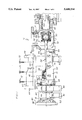
- FIG. 1 is a partially-sectioned side elevational view of a first embodiment of an improved pump according to the present invention
- FIG. 2 is an enlarged sectional view of an example of a first universal joint for use in the pump of FIG. 1;
- FIG. 3 is an enlarged partial sectional view of an example of a second universal joint for use in the pump of FIG. 1 positioned in an extension tube of the pump;
- FIG. 4 is a sectional view of a stator casing, stator and rotor for the pump of FIG. 1;
- FIG. 5 is a sectional view of the stator casing, stator and rotor of FIG. 4, taken along the line 5--5 in FIG. 4;
- FIG. 6 is a side elevational view of an extension tube for the pump of FIG. 1;
- FIG. 7 is a partially-sectioned side elevational view of a second embodiment of an improved pump according to the present invention.
- the pump 10 designed for pumping low to high viscosity fluids and slurries.
- the pump 10 includes an inlet housing 12, an extension tube 14 and a stator casing or housing 16. At least partially enclosed within these elements are a drive shaft 20, a coupling 22, a stator 24 and a rotor 26.
- the coupling 22 includes a first universal joint 30, a connecting rod 32 and a second universal joint 34.
- the inlet housing 12 defines a chamber 40 and a suction port 42 which communicates with the chamber 40.
- the suction port 42 is configured to mate to standard pipe fittings.
- an opening 44 communicates with a tube interior 46 of the extension tube 14.
- the drive shaft 20 extends into the chamber 40 through a packing or shaft sealing device 48 mounted in a stuffing box or seal housing 50.
- the inlet housing 12 includes an access port 52 sealed by a removable door 54 which provides access to the first universal joint 30 for inspection and maintenance.
- the extension tube 14 includes a first or removable section 60 and a second section 62 which may be fixed or removable.
- the first and second sections 60, 62 each define substantially semi-circular upstream flange portions 64 and substantially semi-circular downstream flange portions 66 which cooperate to form radial upstream and downstream flanges near opposite ends of the extension tube 14.
- the upstream flange portions 64 preferably comprise ring portions or flanges located extending around outer surfaces of the first and second sections 60, 62.
- the first and second sections 60, 62 also include longitudinally extending side flanges 68, 70 which are fastened together by threaded fasteners 72 to form the extension tube 14.
- a gasket 74 is positioned between the side flanges 68, 70 to seal the assembled extension tube 14.
- the stator casing 16 consists primarily of a cylindrical shell 80 which at least partially encloses the stator 24.
- a first ring 82 is attached to an outer surface of the shell 80 near an upstream end while a second ring 84 is attached to the outer surface of the shell 80 near a downstream end.
- the downstream flange portions 66 of the extension tube 14 are removably fastened by means of threaded fasteners 86 to the first ring 82 so that the extension tube 14 is attached to the stator casing 16.
- a standard discharge flange 88 defining a discharge port (not shown) is fastened to the second ring 84.
- the stator casing 16, as well as the extension tube 14, is embraced by a plurality of brackets 90 which mount the pump 10 on a substrate (not shown).
- the drive shaft 20 consists of a solid metal shaft supported by bearings (not shown) and located for rotation about a fixed axis 100 aligned with an axis 102 of the stator 24.
- the drive shaft 20 is coupled near one end to a drive head (not shown) and near an opposite end to the first universal joint 30. In operation, the drive shaft 20 transfers rotary power from the drive head (not shown) to the coupling 22.
- first and second universal joints 30, 34 of the coupling 22 comprise gear joints.
- the first universal joint 30 includes a first retainer 110 coupled to the drive shaft 20, a second retainer 112, a sleeve 114 which spaces the first and second retainers 110, 112 to form a socket, and a gear ball 116 coupled to the connecting rod 32.
- Thrust plates 118, 120 separated by a ring gear 122 restrain the gear ball 116 to pivot within a limited angle.
- the gear ball 116 includes external crowned gear teeth 124 and the ring gear 122 includes straight internal gear teeth 126 which receive the external teeth 124 such that the gear ball 116 rotates with the sleeve 114.
- a pair of keys 123, 125 connect the first retainer 110 to the ring gear 122.
- a seal 128 captured on an outer periphery between the second retainer 112 and the thrust plate 120, and on an inner periphery between the connecting rod 32 and a collar 130, protects the universal joint 30 from the fluid or slurry in the chamber 40.
- the second universal joint 34 is similar in construction to the first universal joint 30. As best shown in FIG. 3, the second universal joint 34 includes a first retainer 140 which is typically formed integrally with the rotor 26, a second retainer 142, and a gear ball 144 coupled to the connecting rod 32 near an end of the connecting rod 32 opposite the first universal joint 30.
- the second retainer 142 of the second universal joint 34 is cup-shaped and is coupled directly to the first retainer 140 to define a socket in which the gear ball 144 is positioned.
- the second universal joint 34 includes thrust plates 146, 148 located on either side of a gear ball 144 to pivot within a limited angle.
- the gear ball 144 includes external crowned gear teeth 152 (only one shown) and a ring gear 150 includes straight internal gear teeth 154 which receive external teeth 152 such that the gear ball 144 rotates with the second retainer 142.
- a pair of keys 141 (only one shown) provide a connection between the ring gear 150 and the first retainer 140.
- a seal 156 is captured on an outer periphery between the second retainer 142 and the thrust plate 148, and on an inner periphery between the connecting rod 32 and a collar 158.
- the first and second universal joints 30, 34 and the connecting rod 32 cooperate to transfer rotary power from the axis 100 of the drive shaft 20 (which coincides with the stator axis 102) to the rotor 26.
- the first universal joint 30 couples the drive shaft 20 and the connecting rod 32 in the chamber 40 of the inlet housing 12.
- the second universal joint 34 couples the connecting rod 32 to the rotor 26 in the extension tube 14. Since the connecting rod 32 is fixed to the gear ball elements 116 (FIG. 2) and 144 (FIG. 3) of the universal joints 30, 34 while the drive shaft 20 and the rotor 26 are fixed to the first retainers 110 (FIG. 2) and 140 (FIG. 3), respectively, of the universal joints 30, 34, the connecting rod 32 may pivot through a limited angle relative to the axis 100 of the drive shaft 20 to permit the rotor 26 to move eccentrically about the stator axis 102.
- the stator 24 and the rotor 26 preferably form a progressing cavity gear set.
- the stator 24 comprises an elastomeric sleeve defining an internal passageway 170 which communicates with the extension tube 14 (FIG. 1).
- the internal passageway 170 defines an inner surface 172.
- the stator 24 is enclosed in the stator casing 16 in abutment against the discharge flange 88 (FIG. 5).
- the rotor 26 comprises a worm formed from metal or composite material having an outer surface 174. The rotor 26 abuts against the inner surface 172 of the stator 24, and is connected to the coupling 22 for eccentric movement along the inner surface 172 as power is transferred from the drive shaft 20 (FIG. 1) through the coupling 22 to the rotor 26.
- the inner surface 172 of the stator 24 and the outer surface 174 of the rotor 26 each define helical profiles.
- the helical profiles are preferably derived from cross-sections generated from a combination of line segments, circular arcs and hypocycloidal arcs, and are subject to certain geometric relations which permit the rotor 26 to mesh in the internal passageway 170 of the stator 24.
- a "stator thread number” be one greater than a "rotor thread number.”
- the "rotor thread number” is the number of worm threads on the outer surface of the rotor, while the “stator thread number” is the number of lobes in the cross-section of the stator for receiving worm threads.
- the rotor 26 shown in FIG. 4 has one thread, while the cross-section of the internal passageway 170 shown in FIG. 4 has two lobes for receiving that thread.
- the thread number of the stator is two and the thread number of the rotor is one.
- the ratio of the rotor pitch to the stator pitch preferably equals the ratio of the rotor thread number to the stator thread number.
- the stator pitch is indicated at 180 and the rotor pitch is indicated at 182.
- the rotor pitch 182 is one-half the stator pitch 180, which corresponds to the 1:2 ratio between the rotor thread number and the stator thread number.
- the interaction of the helical profiles of the inner surface 172 of the stator 24 and the outer surface 174 of the rotor 26 produces a series of cavities in the internal passageway 170.
- these cavities move from an upstream end 192 of the internal passageway 172 toward a downstream end 194.
- Fluid or slurry enters into the cavities near an upstream end 192 of the internal passageway 172 facing the extension tube 14 (FIG. 1) and is carried toward the downstream end 194.
- the flow of the fluid or slurry into the cavities creates a pressure gradient which draws additional fluid or slurry through the suction port 42, the chamber 40 and the tube interior 46 toward the internal passageway 172.
- the stator length 196 should be greater than the stator pitch 180. This relationship prevents the cavities in the passageway 170 from communicating simultaneously with both the upstream and downstream ends 192, 194 of the internal passageway 170 and thereby equalizing pressure across the internal passageway 170.
- the extension tube 14 is formed from first and second sections 60, 62 separable along a dividing plane generally dividing the extension tube 14 into upper and lower halves.
- the extension tube 14 is preferably in the form of a surface of rotation with a tube axis 200.
- the side flanges 68, 70 of the first and second sections 60, 62 of the extension tube 14 abut the gasket 74 along the dividing plane, which includes the tube axis 200 and is perpendicular to the plane of the drawing.
- the threaded fasteners 72 are removed, the first and second sections 60, 62 are separable along this plane.
- toggle clamps or other quick acting mechanical fasteners could also be used to facilitate quick attachment and detachment of the sections 60, 62 to and from each other.
- the separation of the first section 60 of the extension tube 14 from the second section 62 exposes the connecting rod 32 and the second universal joint 34 for inspection and maintenance. Furthermore, the removal of the first section 60 creates a sufficient opening for maintenance personnel to inspect the rotor 26 and the stator 24 through the upstream end 192 of the stator 24. It should be noted that although the universal joints 30, 34 have been described with particular reference to gear joints, the split extension tube of the present invention may be used to facilitate maintenance on any type of drive mechanism.
- FIG. 7 shows a so-called "open-throat" pump 210 designed to connect to the bottom of a large hopper or feed chute to pump highly viscous products or semi-dry materials such as filter cakes or paper stock.
- the pump 210 includes an inlet housing 212, an extension tube 214 and a stator casing 216. At least partially enclosed within these elements are a drive shaft 220, a coupling 222, a stator 224 and a rotor 226.
- the coupling 222 includes a first universal joint 230, a connecting rod 232 and a second universal joint 234.
- the stator casing 216, the drive shaft 220, the stator 224 and the rotor 226 are identical in construction to their counterparts 16, 20, 24 and 26 in the pump 10 of FIGS. 1-6, and will not be described further.
- the inlet housing 212 defines a elongated prismatic chamber 240 and a rectangular suction port 242 which is essentially an open upper side of the chamber 240. At one end of the chamber 240, an opening 244 communicates with the extension tube 214. At an opposite end of the chamber 240, the drive shaft 220 extends into the chamber 240 through a shaft sealing device 248 mounted in a stuffing box or seal housing 250.
- the inlet housing 214 also includes an access port 252 sealed by a removable door 254 which provides access to the first universal joint 230 for inspection and maintenance.
- a plug 256 is provided at the bottom of the inlet housing 212 for drainage.
- the extension tube 214 includes a first or removable section 260 and a second or fixed section 262. As with the extension tube 14 of the pump 10, the first and second sections 260, 262 are separable along a dividing plane and are removably fastened to each other, to the inlet housing 212 and to the stator casing 216 by means of threaded fasteners 264.
- the assembled extension tube 214 is cylindrical in shape, and includes an inspection port 268.
- the connecting rod 232 extends across most of the length of the inlet housing 212 and the extension tube 214.
- the connecting rod 232 supports a sleeve 280 having a helical worm or auger 282 which serves to agitate material which accumulates at the bottom of the inlet housing 212 and to drive such material into the extension tube 214.
- the sleeve 280 is secured to the connecting rod 232 at either end by collars 284, 286 which induce the worm 282 to rotate with the connecting rod 232.
- the separation of the extension tubes 14, 214 of the two embodiments 10, 210 into sections 60, 62, 260, 262 removably fastened together by threaded fasteners facilitates the inspection and maintenance of the couplings 22, 222; the stators 24, 224 and the rotors 26, 226 of the two embodiments 10, 210.
Abstract
Description
Claims (16)
Priority Applications (2)
| Application Number | Priority Date | Filing Date | Title |
|---|---|---|---|
| US08/618,926 US5688114A (en) | 1996-03-20 | 1996-03-20 | Progressing cavity pumps with split extension tubes |
| CA002196250A CA2196250A1 (en) | 1996-03-20 | 1997-01-29 | Progressing cavity pumps with split extension tubes |
Applications Claiming Priority (1)
| Application Number | Priority Date | Filing Date | Title |
|---|---|---|---|
| US08/618,926 US5688114A (en) | 1996-03-20 | 1996-03-20 | Progressing cavity pumps with split extension tubes |
Publications (1)
| Publication Number | Publication Date |
|---|---|
| US5688114A true US5688114A (en) | 1997-11-18 |
Family
ID=24479716
Family Applications (1)
| Application Number | Title | Priority Date | Filing Date |
|---|---|---|---|
| US08/618,926 Expired - Lifetime US5688114A (en) | 1996-03-20 | 1996-03-20 | Progressing cavity pumps with split extension tubes |
Country Status (2)
| Country | Link |
|---|---|
| US (1) | US5688114A (en) |
| CA (1) | CA2196250A1 (en) |
Cited By (21)
| Publication number | Priority date | Publication date | Assignee | Title |
|---|---|---|---|---|
| FR2823537A1 (en) * | 2001-04-13 | 2002-10-18 | Pcm Pompes | Pump with spiral rotor and drive has transmission unit with cavities connected by elongated member with end pivots inside tubular sleeve |
| US6491501B1 (en) * | 2000-09-01 | 2002-12-10 | Moyno, Inc. | Progressing cavity pump system for transporting high-solids, high-viscosity, dewatered materials |
| US6497556B2 (en) | 2001-04-24 | 2002-12-24 | Cdx Gas, Llc | Fluid level control for a downhole well pumping system |
| US6604910B1 (en) | 2001-04-24 | 2003-08-12 | Cdx Gas, Llc | Fluid controlled pumping system and method |
| US20030178231A1 (en) * | 2000-07-17 | 2003-09-25 | Theodor Bruckmann | Assembly of a drive shaft with the cutting head hub of a submersible granulator |
| US20040131491A1 (en) * | 2001-11-07 | 2004-07-08 | Jean-Pierre Marielle | Moineau pump pumping device |
| US20080037361A1 (en) * | 2006-02-15 | 2008-02-14 | Jerry Fleishman | Mixer apparatus |
| US20090110578A1 (en) * | 2007-10-30 | 2009-04-30 | Moyno, Inc. | Progressing cavity pump with split stator |
| GB2455597A (en) * | 2008-07-28 | 2009-06-17 | Mono Pumps Ltd | A progressive cavity pump having a removable suction chamber |
| US20100196182A1 (en) * | 2007-08-17 | 2010-08-05 | Denise Loeker | Eccentric screw pump with split stator |
| WO2011146245A1 (en) * | 2010-05-20 | 2011-11-24 | Moyno, Inc. | Gear joint with super finished surfaces |
| US8215014B2 (en) | 2007-10-31 | 2012-07-10 | Moyno, Inc. | Method for making a stator |
| WO2013049030A1 (en) * | 2011-09-30 | 2013-04-04 | Moyno, Inc. | Universal joint with cooling system |
| WO2016198037A1 (en) * | 2015-06-12 | 2016-12-15 | Netzsch Pumpen & Systeme Gmbh | Pump housing for an eccentric screw pump, and eccentric screw pump equipped therewith |
| EP3112682A3 (en) * | 2014-05-12 | 2017-03-08 | Hugo Vogelsang Maschinenbau GmbH | Eccentric screw pump with assembly through the hollow rotor |
| WO2018087248A1 (en) * | 2016-11-10 | 2018-05-17 | Seepex Gmbh | Eccentric screw pump |
| WO2020186324A1 (en) * | 2019-03-15 | 2020-09-24 | Agostini Leandro Jose | Progressive cavity pump for the paint-mixing industry |
| US11174860B2 (en) * | 2017-03-30 | 2021-11-16 | Roper Pump Company | Progressive cavity pump with integrated heating jacket |
| US11326595B2 (en) * | 2016-11-10 | 2022-05-10 | Seepex Gmbh | Eccentric screw compressor with exposable rotor connector |
| US11391280B2 (en) * | 2017-10-20 | 2022-07-19 | Circor Pumps North America, Llc. | Dismounting device for progressive cavity pumps |
| DE102021111925A1 (en) | 2021-05-07 | 2022-11-10 | Seepex Gmbh | progressing cavity pump |
Citations (10)
| Publication number | Priority date | Publication date | Assignee | Title |
|---|---|---|---|---|
| US1892217A (en) * | 1930-05-13 | 1932-12-27 | Moineau Rene Joseph Louis | Gear mechanism |
| US2028407A (en) * | 1932-04-29 | 1936-01-21 | Moineau Rene Joseph Louis | Gear mechanism |
| US2346426A (en) * | 1941-10-30 | 1944-04-11 | Fmc Corp | Flexible rotary drive coupling |
| US2545626A (en) * | 1946-12-17 | 1951-03-20 | Robbins & Myers | Spiral gear pump and allied device |
| US2733854A (en) * | 1956-02-07 | chang | ||
| US3011445A (en) * | 1957-11-13 | 1961-12-05 | Robbin & Myers Inc | Helical gear pump with by-pass |
| DE2040748A1 (en) * | 1970-08-17 | 1972-02-24 | Willy John | Rotary screw pump - with shaft and screw element |
| DE2331585A1 (en) * | 1973-06-20 | 1975-05-15 | Netzsch Mohnopumpen Gmbh | Screw type pump for sludge material - has rotating paddle in filling hopper to prevent bridging of feed material |
| US4591322A (en) * | 1983-12-28 | 1986-05-27 | Heishin Sobi Kabushiki Kaisha | Eccentric archimedian screw pump of rotary displacement type |
| US4639200A (en) * | 1985-05-09 | 1987-01-27 | Robbins & Myers, Inc. | Sealing apparatus for a gear ball joint |
-
1996
- 1996-03-20 US US08/618,926 patent/US5688114A/en not_active Expired - Lifetime
-
1997
- 1997-01-29 CA CA002196250A patent/CA2196250A1/en not_active Abandoned
Patent Citations (10)
| Publication number | Priority date | Publication date | Assignee | Title |
|---|---|---|---|---|
| US2733854A (en) * | 1956-02-07 | chang | ||
| US1892217A (en) * | 1930-05-13 | 1932-12-27 | Moineau Rene Joseph Louis | Gear mechanism |
| US2028407A (en) * | 1932-04-29 | 1936-01-21 | Moineau Rene Joseph Louis | Gear mechanism |
| US2346426A (en) * | 1941-10-30 | 1944-04-11 | Fmc Corp | Flexible rotary drive coupling |
| US2545626A (en) * | 1946-12-17 | 1951-03-20 | Robbins & Myers | Spiral gear pump and allied device |
| US3011445A (en) * | 1957-11-13 | 1961-12-05 | Robbin & Myers Inc | Helical gear pump with by-pass |
| DE2040748A1 (en) * | 1970-08-17 | 1972-02-24 | Willy John | Rotary screw pump - with shaft and screw element |
| DE2331585A1 (en) * | 1973-06-20 | 1975-05-15 | Netzsch Mohnopumpen Gmbh | Screw type pump for sludge material - has rotating paddle in filling hopper to prevent bridging of feed material |
| US4591322A (en) * | 1983-12-28 | 1986-05-27 | Heishin Sobi Kabushiki Kaisha | Eccentric archimedian screw pump of rotary displacement type |
| US4639200A (en) * | 1985-05-09 | 1987-01-27 | Robbins & Myers, Inc. | Sealing apparatus for a gear ball joint |
Cited By (44)
| Publication number | Priority date | Publication date | Assignee | Title |
|---|---|---|---|---|
| US20030178231A1 (en) * | 2000-07-17 | 2003-09-25 | Theodor Bruckmann | Assembly of a drive shaft with the cutting head hub of a submersible granulator |
| US6491501B1 (en) * | 2000-09-01 | 2002-12-10 | Moyno, Inc. | Progressing cavity pump system for transporting high-solids, high-viscosity, dewatered materials |
| US6939235B2 (en) * | 2000-11-17 | 2005-09-06 | Bkg Bruckmann & Kreyenborg Granuliertechnik Gmbh | Assembly of a drive shaft with the cutting head hub of a submersible granulator |
| FR2823537A1 (en) * | 2001-04-13 | 2002-10-18 | Pcm Pompes | Pump with spiral rotor and drive has transmission unit with cavities connected by elongated member with end pivots inside tubular sleeve |
| US6945755B2 (en) | 2001-04-24 | 2005-09-20 | Cdx Gas, Llc | Fluid controlled pumping system and method |
| US20050079063A1 (en) * | 2001-04-24 | 2005-04-14 | Cdx Gas, Llc A Texas Limited Liability Company | Fluid controlled pumping system and method |
| US6604910B1 (en) | 2001-04-24 | 2003-08-12 | Cdx Gas, Llc | Fluid controlled pumping system and method |
| US6497556B2 (en) | 2001-04-24 | 2002-12-24 | Cdx Gas, Llc | Fluid level control for a downhole well pumping system |
| US20040131491A1 (en) * | 2001-11-07 | 2004-07-08 | Jean-Pierre Marielle | Moineau pump pumping device |
| US6962489B2 (en) * | 2001-11-07 | 2005-11-08 | Pcm Pompes | Moineau pumping device having a ball coupling |
| US20080037361A1 (en) * | 2006-02-15 | 2008-02-14 | Jerry Fleishman | Mixer apparatus |
| US8439659B2 (en) * | 2007-08-17 | 2013-05-14 | Seepex Gmbh | Eccentric screw pump with split stator |
| US20100196182A1 (en) * | 2007-08-17 | 2010-08-05 | Denise Loeker | Eccentric screw pump with split stator |
| US8182252B2 (en) | 2007-10-30 | 2012-05-22 | Moyno, Inc. | Progressing cavity pump with split stator |
| US20090110578A1 (en) * | 2007-10-30 | 2009-04-30 | Moyno, Inc. | Progressing cavity pump with split stator |
| US8215014B2 (en) | 2007-10-31 | 2012-07-10 | Moyno, Inc. | Method for making a stator |
| GB2455597A (en) * | 2008-07-28 | 2009-06-17 | Mono Pumps Ltd | A progressive cavity pump having a removable suction chamber |
| CN102099581A (en) * | 2008-07-28 | 2011-06-15 | 蒙诺泵有限公司 | Pump |
| US20110123380A1 (en) * | 2008-07-28 | 2011-05-26 | Mono Pumps Limited | Pump |
| WO2010012993A3 (en) * | 2008-07-28 | 2010-09-02 | Mono Pumps Limited | Pump |
| GB2455597B (en) * | 2008-07-28 | 2009-12-09 | Mono Pumps Ltd | Pump |
| US9777728B2 (en) * | 2008-07-28 | 2017-10-03 | Nov Process & Flow Technologies Uk Limited | Pump with stator and rotor section attachment features |
| WO2011146245A1 (en) * | 2010-05-20 | 2011-11-24 | Moyno, Inc. | Gear joint with super finished surfaces |
| US8246477B2 (en) | 2010-05-20 | 2012-08-21 | Moyno, Inc. | Gear joint with super finished surfaces |
| WO2013049030A1 (en) * | 2011-09-30 | 2013-04-04 | Moyno, Inc. | Universal joint with cooling system |
| US9435383B2 (en) | 2011-09-30 | 2016-09-06 | Moyno, Inc. | Universal joint with cooling system |
| US10233924B2 (en) | 2014-05-12 | 2019-03-19 | Hugo Vogelsang Maschinenbau Gmbh | Eccentric screw pump |
| EP3112682A3 (en) * | 2014-05-12 | 2017-03-08 | Hugo Vogelsang Maschinenbau GmbH | Eccentric screw pump with assembly through the hollow rotor |
| EP3855021A1 (en) | 2014-05-12 | 2021-07-28 | Hugo Vogelsang Maschinenbau GmbH | Eccentric screw pump with mounting through the drive shaft |
| US11035361B2 (en) | 2014-05-12 | 2021-06-15 | Hugo Vogelsang Maschinenbau Gmbh | Eccentric screw pump |
| US10767646B2 (en) | 2015-06-12 | 2020-09-08 | Netzsch Pumpen & Systeme Gmbh | Pump housing for an eccentric screw pump and an eccentric screw pump equipped therewith |
| CN107743548A (en) * | 2015-06-12 | 2018-02-27 | 耐驰泵及系统有限公司 | Pump case for eccentrie helical totorpump and the eccentrie helical totorpump equipped with the pump case |
| CN107743548B (en) * | 2015-06-12 | 2019-05-17 | 耐驰泵及系统有限公司 | Pump case for eccentrie helical totorpump and the eccentrie helical totorpump equipped with the pump case |
| WO2016198037A1 (en) * | 2015-06-12 | 2016-12-15 | Netzsch Pumpen & Systeme Gmbh | Pump housing for an eccentric screw pump, and eccentric screw pump equipped therewith |
| US11378078B2 (en) | 2016-11-10 | 2022-07-05 | Seepex Gmbh | Eccentric screw pump with telescoping housing |
| CN109952436B (en) * | 2016-11-10 | 2021-03-02 | 西派克有限公司 | Eccentric screw pump |
| WO2018087248A1 (en) * | 2016-11-10 | 2018-05-17 | Seepex Gmbh | Eccentric screw pump |
| US11326595B2 (en) * | 2016-11-10 | 2022-05-10 | Seepex Gmbh | Eccentric screw compressor with exposable rotor connector |
| CN109952436A (en) * | 2016-11-10 | 2019-06-28 | 西派克有限公司 | eccentric screw pump |
| US11174860B2 (en) * | 2017-03-30 | 2021-11-16 | Roper Pump Company | Progressive cavity pump with integrated heating jacket |
| US11391280B2 (en) * | 2017-10-20 | 2022-07-19 | Circor Pumps North America, Llc. | Dismounting device for progressive cavity pumps |
| WO2020186324A1 (en) * | 2019-03-15 | 2020-09-24 | Agostini Leandro Jose | Progressive cavity pump for the paint-mixing industry |
| US11655814B2 (en) | 2019-03-15 | 2023-05-23 | Agostini Leandro Jose | Progressive cavity pump for the tintometric industry |
| DE102021111925A1 (en) | 2021-05-07 | 2022-11-10 | Seepex Gmbh | progressing cavity pump |
Also Published As
| Publication number | Publication date |
|---|---|
| CA2196250A1 (en) | 1997-09-21 |
Similar Documents
| Publication | Publication Date | Title |
|---|---|---|
| US5688114A (en) | Progressing cavity pumps with split extension tubes | |
| US11713757B2 (en) | Pump integrated with two independently driven prime movers | |
| US5195882A (en) | Gerotor pump having spiral lobes | |
| US4923376A (en) | Moineau pump with rotating closed end outer member and nonrotating hollow inner member | |
| US4140444A (en) | Flexible shaft assembly for progressing cavity pump | |
| US5139400A (en) | Progressive cavity drive train | |
| US4591322A (en) | Eccentric archimedian screw pump of rotary displacement type | |
| US3216768A (en) | Pump construction | |
| EP0003676B1 (en) | Helical gear pumps, compressors or motors | |
| US5549464A (en) | Drive arrangement for progressing cavity pump | |
| US8182252B2 (en) | Progressing cavity pump with split stator | |
| US20120328462A1 (en) | Positive Displacement Rotary Pumps with Improved Cooling | |
| KR101728260B1 (en) | Multiple pump arrangement | |
| US2446194A (en) | Pump construction | |
| EP0100627B1 (en) | Helical gear pump | |
| US6926492B2 (en) | Suction housing for rotor/stator pump | |
| US4185839A (en) | Packing gland for pump shaft seal | |
| JPS63302189A (en) | Eccentric screw pump | |
| KR100375943B1 (en) | A fluid-conveying device using a rotary valve | |
| JPS62321B2 (en) | ||
| CN214398558U (en) | Flexible conveyor | |
| EP0457491B1 (en) | Gerotor pumps | |
| US2698577A (en) | Nutating piston fluid displacement device | |
| CA1091050A (en) | Flexible shaft assembly for progressing cavity pump | |
| RU32211U1 (en) | Screw pump |
Legal Events
| Date | Code | Title | Description |
|---|---|---|---|
| AS | Assignment |
Owner name: ROBBINS & MYERS, INC., OHIO Free format text: ASSIGNMENT OF ASSIGNORS INTEREST;ASSIGNORS:MILLINGTON, JOHN A.;WILD, ALAN G.;REEL/FRAME:007984/0291 Effective date: 19960315 |
|
| STCF | Information on status: patent grant |
Free format text: PATENTED CASE |
|
| FPAY | Fee payment |
Year of fee payment: 4 |
|
| FPAY | Fee payment |
Year of fee payment: 8 |
|
| AS | Assignment |
Owner name: J.P. MORGAN TRUST COMPANY, N.A., AS AGENT, ILLINOI Free format text: SECURITY INTEREST;ASSIGNOR:ROBBINS & MYERS, INC.;REEL/FRAME:017492/0424 Effective date: 20051223 |
|
| AS | Assignment |
Owner name: ROBBINS & MYERS, INC., OHIO Free format text: PATENT RELEASE OF SECURITY INTEREST;ASSIGNOR:BANK OF NEW YORK TRUST COMPANY, N.A., THE, AS SUCCESSOR TO J.P. MORGAN TRUST COMPANY, AS AGENT;REEL/FRAME:018866/0303 Effective date: 20061219 |
|
| AS | Assignment |
Owner name: MOYNO, INC., OHIO Free format text: ASSIGNMENT OF ASSIGNORS INTEREST;ASSIGNOR:ROBBINS & MYERS, INC.;REEL/FRAME:022231/0997 Effective date: 20090203 |
|
| FPAY | Fee payment |
Year of fee payment: 12 |