US5689330A - Laser plane generator having self-calibrating levelling system - Google Patents
Laser plane generator having self-calibrating levelling system Download PDFInfo
- Publication number
- US5689330A US5689330A US08/415,344 US41534495A US5689330A US 5689330 A US5689330 A US 5689330A US 41534495 A US41534495 A US 41534495A US 5689330 A US5689330 A US 5689330A
- Authority
- US
- United States
- Prior art keywords
- inclination
- signal
- input
- levelling
- self
- Prior art date
- Legal status (The legal status is an assumption and is not a legal conclusion. Google has not performed a legal analysis and makes no representation as to the accuracy of the status listed.)
- Expired - Lifetime
Links
Images


Classifications
-
- G—PHYSICS
- G01—MEASURING; TESTING
- G01B—MEASURING LENGTH, THICKNESS OR SIMILAR LINEAR DIMENSIONS; MEASURING ANGLES; MEASURING AREAS; MEASURING IRREGULARITIES OF SURFACES OR CONTOURS
- G01B11/00—Measuring arrangements characterised by the use of optical techniques
- G01B11/26—Measuring arrangements characterised by the use of optical techniques for measuring angles or tapers; for testing the alignment of axes
-
- G—PHYSICS
- G01—MEASURING; TESTING
- G01C—MEASURING DISTANCES, LEVELS OR BEARINGS; SURVEYING; NAVIGATION; GYROSCOPIC INSTRUMENTS; PHOTOGRAMMETRY OR VIDEOGRAMMETRY
- G01C15/00—Surveying instruments or accessories not provided for in groups G01C1/00 - G01C13/00
- G01C15/002—Active optical surveying means
- G01C15/004—Reference lines, planes or sectors
Definitions
- This invention relates generally to laser plane generators used in the construction industry and especially those which are self-levelling. More particularly, the invention relates to a method and apparatus for calibration of the self-levelling mechanism of the laser plane generator.
- a laser plane generator includes a laser source for generating a beam of collimated light and a rotating mechanism for rotating the beam of light about an axis to generate a plane of light. Such device may additionally pass a portion of the beam of light along the axis of rotation of the beam in order to provide a reference beam that is perpendicular to the light plane.
- Such laser apparatus finds use in surveying applications as well as in guiding various forms of automatically controlled construction equipment, such as road graders, dozers, excavators, and the like.
- it is necessary to have a known orientation of the laser plane with respect to true earth reference.
- the laser plane is oriented perpendicular to the earth's gravitational field.
- levelling of the apparatus may be accomplished either manually or by a self-levelling mechanism.
- a self-levelling mechanism typically includes an inclination sensor aligned with each axis of the apparatus, which typically includes three perpendicular axes.
- each inclinometer sensor The resistance of a conductive fluid in a vial in each inclinometer sensor is utilized to operate servo motors in order to drive the orientation of the beam until the inclinometer indicates a level orientation.
- the laser plane may be oriented at an angle with respect to the earth's horizontal by rotating the inclinometer according to the desired slope. This will cause the self-levelling mechanism to orient at least one axis of the apparatus according to the offset angle of its respective inclinometer.
- Self-levelling laser plane generators require factory calibration, and occasional field calibration after the unit has left the factory, of the self-levelling mechanism so that the angle of the laser plane matches that entered by the operator.
- Such calibration typically includes providing a mechanical adjustment device, such as a screw shaft or a mechanical potentiometer, which is accessible only with the housing of the apparatus removed or through an external access opening, in order to provide adjustment of the position of each inclinometer on the apparatus chassis or to electrically adjust the output signal produced by the inclinometer.
- the adjustment device may be adjusted until the laser plane produced by the apparatus is perpendicular to the earth's gravitational field.
- One difficulty with such calibration arrangement is that it requires disassembly of the unit in order to perform the calibration.
- the present invention provides a method and apparatus for electronically calibrating the levelling system of a laser plane generator in a manner which is easy to perform by factory and field operators and which is reliable and tamper resistant.
- a self-levelling laser generator and calibration method includes a light source for producing a beam of collimated light and an inclination sensor mounted to rotate with the light source about an axis of the laser generator.
- the inclination sensor produces an output that is an indication of the magnitude of inclination of the housing about the axis.
- a levelling mechanism is provided which is responsive to a drive signal in order to adjust the inclination of the beam about the axis.
- a computer-based control is provided.
- An input is provided to the control for entering data indicative of a deviation between the inclination of the beam and a predetermined grade.
- the control produces a drive signal for the levelling mechanism that is a function of the value of the inclination sensor output and any deviation entered through the input.
- an electronically controllable signal source which responds to a command by producing a signal having a particular value.
- the signal produced by the signal source is combined with the output of the inclination sensor in order to produce a drive signal which is provided to the levelling mechanism to alter the orientation of the laser generator about the axis.
- a command is provided to the signal source by a programmed computer to produce a signal which, when combined with the output of the inclination sensor, produces a drive signal to orient the generator on a predetermined grade.
- the temperature of the inclination sensor is preferably sensed and used to compensate the combined output signal.
- the command signal is preferably established as a function of calibration counts determined during a calibration of the laser generator.
- a calibration range having at least a plurality of first active targets and a plurality of second targets.
- Each of the first and second targets is arranged radially around the generator with the second targets being further than the first targets from the generator.
- a calibration computer processes the outputs of the active targets into a digital data signal which is an indication of the inclination of the beam about the axis. The inclination is determined from an output of each active target indicating which portion of that target is contacted by the beam.
- the digital data signal is provided to the laser generator input for use by the laser generator control in correcting the orientation of the beam.
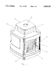
- FIG. 1 is a perspective view of a laser plane generator incorporating the invention
- FIG. 2 is a block diagram of a self-calibrating levelling system according to the invention.
- FIG. 3 is a flowchart of a factory calibration function
- FIG. 4 is a flowchart of a field calibration function
- FIG. 5 is a process flow diagram of a field calibration procedure
- FIG. 6 is a block diagram of a test range according to the invention.
- a self-levelling laser plane generator 10 includes a housing 12 and a plurality of transparent windows 14 in the housing for conducting a rotating laser beam from a rotating head (not shown) while keeping debris and the like from the interior of the housing.
- a window 16 is provided on an upper surface of the housing in order to transmit a beam of collimated light perpendicular to the laser plane transmitted through windows 14.
- An additional window may be provided on the bottom of the housing to transmit an additional perpendicular beam.
- Such laser plane generator is well known in the art and is disclosed in U.S. Pat. No.
- Laser plane generator 10 additionally includes a user input device 20, which, in the illustrative embodiment, is a keypad made up of a plurality of individual key switches 22. Keypad 22 preferably is a mylar switch panel in order to sealingly engage the surrounding portions of housing 12 and thereby keep debris and moisture from the interior housing 12.
- a user input device 20 which, in the illustrative embodiment, is a keypad made up of a plurality of individual key switches 22.
- Keypad 22 preferably is a mylar switch panel in order to sealingly engage the surrounding portions of housing 12 and thereby keep debris and moisture from the interior housing 12.
- Other input devices such as capacitive touch panels, individual switches, voice recognition systems, RF and infrared remote control, and the like may be utilized.
- Laser plane generator 10 includes a self-levelling mechanism 18, which is capable of aligning each of the three mutually orthogonal axes of apparatus 10 with true earth horizontal (FIG. 2).
- Self-levelling mechanism 18 includes an inclinometer, or inclination sensor, 24 aligned with each major axis of the laser plane generator, although only one is illustrated in FIG. 2.
- Inclinometer 24 includes first and second spaced apart input electrodes 26 and an output electrode 28.
- An inclinometer drive circuit 30 applies a square wave signal across leads 32a, 32b connected with electrodes 26.
- An output signal taken from output electrode 28, which is a function of the direction and degree of tilt of inclinometer 24, is provided as an input to an inclination summer and amplifier circuit 34.
- An output 36 of summer and amplifier circuit 34 is provided as an input to a microprocessor 38.
- a temperature sensitive thermistor 40 which is in temperature sensing proximity with the environment of inclinometer 24, provides inputs at 42a, 42b to microprocessor 38.
- Microprocessor 38 includes outputs 44a, 44b, and 44c which supply a digital command to an electronically controlled signal source such as a digital potentiometer 46.
- An output 48 of digital potentiometer 46 is provided as an input to inclination summer and amplifier circuit 34.
- Microprocessor 38 additionally includes output lines 50a, 50b, which are provided as inputs to a motor drive circuit 52.
- Motor drive circuit 52 controls movement of a servo motor 54, which adjusts the position of the beam in one axis.
- the self-levelling mechanism 18, illustrated in FIG. 2 provides self-levelling capabilities for apparatus 10 in one of three mutually perpendicular axes. For each additional axes to be self-levelled, the hardware illustrated in FIG.
- Signal source 46 could be accomplished by other programmable circuits such as an amplifier having a programmable gain. Furthermore, signal source 46 could be combined with summer and amplifier circuit 34 in a combined circuit. Indeed, the techniques of the present invention could be carried out entirely in software with only calibration data, inclination sensor output and temperature data being provided as inputs to a programmed computer.
- Input device 20 is connected with microprocessor 38 through conventional multiplexing techniques in order to provide user input selections of commands utilized in the calibration of apparatus 10 as will be set forth in more detail below.
- Inclination drive circuit 30 applies a square wave to input electrodes 26 of inclinometer 24 in response to a command from microcomputer 38 provided on an input 31.
- Inclination summer and amplifier circuit 34 sums the output of inclinometer 24 measured at electrode 28 with an offset value provided by output 48 of digital potentiometer 46. The summation of these two signals is amplified and provided on output 36 as an input to microprocessor 38. The level of the offset produced on output 48 of digital potentiometer 46 is selected by a digital command produced by microprocessor 38 on its outputs 44a-44c.
- the output produced by microprocessor 38 is a function of the temperature of the inclinometer as monitored by thermistor 40, the tilt of the inclinometer, and calibration numbers entered by the user to input keys 20, as will be described in more detail below.
- the amount the inclinometer will drift is a function of its tilt and temperature.
- Self-levelling mechanism 18 compensates for this drift by measuring the tilt and temperature of inclinometer 24 and then calculating a new inclinometer output voltage on line 36 that is considered null. Once the tilt and temperature of inclinometer 24 are known, this information is fit to a drift/tilt verses temperature curve in microprocessor 38. The value obtained from this evaluation is multiplied by the tilt of the inclinometer to determine drift.
- Calibration of self-levelling mechanism 18 is accomplished by measuring a calibration error of laser plane generator 10 and adding or subtracting calibration counts via input device 20 or data port 21.
- the calibration count changes the setting of each digital potentiometer and, thereby, inclinometer 24, with each calibration count changing the calibration by a predetermined value.
- each calibration count is equal to 4 arcseconds.
- the number of calibration counts is utilized by microprocessor 38 to determine the tilt of each inclinometer 24. Thus, for example, if the calibration is set to 25 calibration counts, the tilt of inclinometer 24 is 100 arcseconds.
- Laser plane generator 10 may be calibrated after manufacture in the factory, or when returned to the factory or repair facility for repair and/or service, utilizing an interactive calibration range 56 (FIGS. 3 and 6).
- Calibration range 56 includes a first pair of active targets 58a and 60a; a second pair of active targets 58b and 60b oriented perpendicular to the first pair; and a third pair of active targets 58c and 60c oriented perpendicular to the second pair. All active targets 58a-58c and 60a-60c provide inputs to a calibration computer 62.
- Calibration computer 62 has an output 64, which provides digital data to data port 21 of self-levelling mechanism 18.
- the effective separation between each of the targets 58a-58c and the associated targets 60a-60c is preferably on the order of approximately 100-180 feet.
- Calibration range 56 operates as follows. Laser plane generator 10 is set upon a surface S, which does not have to be perfectly level, and an input command is provided from calibration computer 62 through data port 21 to rotate beam B from a first position which passes through targets 58a and 60a, then through targets 58b and 60b and then through targets 58c and 60c. The portion of each target struck by the beam is provided as input to calibration computers 62, which stores the results therein. The scanning of the beam may be incremental or continuous rotation. The calibration computer calculates from the six (6) readings from the six (6) targets whether the generated surface is a plane and, if so, any error in the inclination of the plane. If the surface generated by beam B is not a plane, then the optics are adjusted. If the plane is inclined from earth's horizontal, or other predetermined grade, the amount of error is provided to data port 21.
- Self-levelling mechanism 10 performs a factory calibration routine 68 (FIG. 3). The routine is initiated upon microprocessor 68 sensing (70) the presence of data at data port 21. The presence of data on data port 21 is interpreted by microprocessor 68 as a command to place the self-levelling mechanism in an automatic mode (72) which causes microprocessor 38 to rotate the beam head. It is then determined at 74 whether the laser plane generator is in an upright position, as illustrated in FIG. 6, or is in a lay down position, which is utilized to calibrate the self-levelling mechanism with respect to the beam transmitted through window 16, by monitoring a tilt-switch (not shown).
- control If it is determined at 74 that the control is in an upright position, it is then determined (76) whether the data received from calibration computer 62 indicates the presence of a calibration error. If so, microprocessor 68 increments (78) the command provided on output lines 44a-44c to digital potentiometer 46 and the calibration count is saved (80) in microcomputer 38. It is then determined at 82 whether the calibration is complete. If calibration is not finished, then control passes to control function 72 where additional calibration data is processed by repeating the procedure.
- Laser plane generator 10 may be calibrated without calibration range 56 utilizing a field calibration procedure 90 (FIG. 5) and routine 91 (FIG. 4).
- the field calibration mode is established (92) by the user actuating one or more key switches 22 in a particular manner, which results in a particular mode of operation of one or more indicators.
- the key switches that are utilized are normally used for another purpose and, preferably, more than one must be actuated in order to enter the field calibration mode. This inhibits the incidental invoking of the calibration mode, which could result in a miscalibration of the apparatus.
- the automatic mode is entered (94), it is determined at 96 whether the apparatus 10 is being calibrated in a lay down or upright position by monitoring a tilt-switch (not shown).
- the laser plane generator is set on a surface and is allowed to self-level.
- the position of the stationary beam is marked on a distant wall; for example, one separated from the generator by approximately 100-180 feet.
- the housing of the unit is then rotated 180° and the beam repositioned at the same area of the wall.
- the new location of the spot is marked and one-half the distance between the two spots in the vertical direction is measured in order to arrive at a calibration error.
- a particular sequence of key switches designated A and B, are actuated in order to enter the calibration count, if a calibration error is present (98). This causes microprocessor 38 to increment digital potentiometer 46 (100) and the entered calibration count is stored (102) in microprocessor 38.
- the laser plane generator is transported to the position of the target and the beam directed back towards its original position.
- Two targets are utilized in the lay down mode calibration. The position of the beam on both targets, which are spaced about approximately the calibration distance of, for example, 100-180 feet, are measured in both positions of the instrument and used to determine the calibration error as would be apparent to one of ordinary skill in the art.
- microprocessor 38 is an 8-bit microcomputer Model No. M68HC705B5 which is marketed by Motorola.
- Digital potentiometer 46 is a commercially available circuit, which is marketed by Dallas Semiconductor under Model No. DS 1267 SN-10.
- Inclinometer 24 is a commercially available inclination sensor which is marketed by Spectron Specialty Glass under Model No. SH50055-A-009.
- Targets 58a-58c and 60a-60c utilized with calibration range 56 may be of the same general type disclosed in U.S. Pat. No. 5,243,398, which is commonly assigned with the present application, the disclosure of which is hereby incorporated herein by reference.
- the present invention provides a unique self-levelling mechanism for a laser plane generator which may be calibrated without requiring removal of the housing of the apparatus or providing of an access opening for mechanical adjustment. Furthermore, special calibration knobs and shafts, which may invite tampering by the user, resulting in miscalibration of the apparatus, are avoided.
- the present invention provides a method of calibrating a self-levelling mechanism in a laser plane generator, which is easy to explain in manuals and easy to implement by the field technician. Furthermore, a factory calibration range is provided which makes calibration of the self-levelling mechanism almost fully automated.
- the principles of the present invention may be applied to both a laser plane generator that is self-levelling to a horizontal inclination and to a laser plane generator that is self-levelling to a grade.
Abstract
Description
Claims (28)
Priority Applications (1)
| Application Number | Priority Date | Filing Date | Title |
|---|---|---|---|
| US08/415,344 US5689330A (en) | 1995-04-03 | 1995-04-03 | Laser plane generator having self-calibrating levelling system |
Applications Claiming Priority (1)
| Application Number | Priority Date | Filing Date | Title |
|---|---|---|---|
| US08/415,344 US5689330A (en) | 1995-04-03 | 1995-04-03 | Laser plane generator having self-calibrating levelling system |
Publications (1)
| Publication Number | Publication Date |
|---|---|
| US5689330A true US5689330A (en) | 1997-11-18 |
Family
ID=23645323
Family Applications (1)
| Application Number | Title | Priority Date | Filing Date |
|---|---|---|---|
| US08/415,344 Expired - Lifetime US5689330A (en) | 1995-04-03 | 1995-04-03 | Laser plane generator having self-calibrating levelling system |
Country Status (1)
| Country | Link |
|---|---|
| US (1) | US5689330A (en) |
Cited By (37)
| Publication number | Priority date | Publication date | Assignee | Title |
|---|---|---|---|---|
| US5907907A (en) * | 1996-01-31 | 1999-06-01 | Kabushiki Kaisha Topcon | Laser leveling system |
| USD416856S (en) * | 1997-11-11 | 1999-11-23 | Kabushiki Kaisha | Rotating laser |
| USD420972S (en) * | 1998-08-14 | 2000-02-22 | The Stanley Works | Rotating laser |
| US6037874A (en) * | 1998-06-30 | 2000-03-14 | Zircon Corporation | Electronic level with laser inclination indicator |
| USD429481S (en) * | 1997-11-10 | 2000-08-15 | Topcon Corporation | Rotating laser |
| US6108076A (en) * | 1998-12-21 | 2000-08-22 | Trimble Navigation Limited | Method and apparatus for accurately positioning a tool on a mobile machine using on-board laser and positioning system |
| US6195901B1 (en) | 1997-05-28 | 2001-03-06 | Laser Alignment, Inc. | Laser beam projector power and communication system |
| US6253160B1 (en) | 1999-01-15 | 2001-06-26 | Trimble Navigation Ltd. | Method and apparatus for calibrating a tool positioning mechanism on a mobile machine |
| WO2001069173A1 (en) * | 2000-03-10 | 2001-09-20 | Spectra Precision Inc. | Versatile transmitter and receiver for position measurement |
| US6314650B1 (en) | 1999-02-11 | 2001-11-13 | Laser Alignment, Inc. | Laser system for generating a reference plane |
| DE10054627A1 (en) * | 2000-11-03 | 2002-05-16 | Nestle & Fischer Gmbh & Co Kg | Method and device for aligning a light beam generated by a rotating laser |
| US6621560B2 (en) * | 2002-01-09 | 2003-09-16 | Trimble Navigation Limited | Laser transmitter with thermally induced error compensation and method of transmitter compensation |
| US6628373B2 (en) * | 2002-01-09 | 2003-09-30 | Trimble Navigation Limited | Laser transmitter with thermally induced error compensation and method of transmitter compensation |
| US6704097B2 (en) * | 2000-05-31 | 2004-03-09 | Hilti Aktiengesellschaft | Optoelectronic distance measuring device and operating method determined therefor |
| US20050117153A1 (en) * | 2003-12-02 | 2005-06-02 | Keijun Kishi | Interchangeable horizontally and vertically laser suitable for use in small spaces |
| US6938350B1 (en) | 2002-12-31 | 2005-09-06 | PLS—Pacific Laser Systems | Apparatus for producing a reference plane |
| US6981333B2 (en) * | 1999-12-08 | 2006-01-03 | Pruftechnik Dieter Busch Ag | Ergonomic, interference signal-reducing position measurement probe for mutual alignment of bodies |
| US7013570B2 (en) | 2003-06-18 | 2006-03-21 | Irwin-Industrial Tool Company | Stud finder |
| US20060242850A1 (en) * | 2005-04-29 | 2006-11-02 | Hilti Aktiengesellschaft | Tiltable construction laser |
| US20070028470A1 (en) * | 2005-08-04 | 2007-02-08 | Nash Derek J | Laser reference device |
| US20070085028A1 (en) * | 2005-10-17 | 2007-04-19 | Hilti Aktiengesellschaft | Tilt control method |
| US20070180716A1 (en) * | 2003-06-23 | 2007-08-09 | Mikael Hertzman | Surveying instrument with compensation for mechanical errors |
| US7269907B2 (en) | 2003-07-01 | 2007-09-18 | Irwin Industrial Tool Company | Laser line generating device with swivel base |
| US7278218B2 (en) | 2003-06-18 | 2007-10-09 | Irwin Industrial Tool Company | Laser line generating device with swivel base |
| US20080120853A1 (en) * | 2006-11-13 | 2008-05-29 | The Stanley Works | Pipe laser |
| US7497018B2 (en) | 2006-05-26 | 2009-03-03 | William Hersey | Laser-based alignment tool |
| US20090105986A1 (en) * | 2007-10-23 | 2009-04-23 | Los Alamos National Security, Llc | Apparatus and method for mapping an area of interest |
| US20090120914A1 (en) * | 2006-05-01 | 2009-05-14 | Wayne Lawrence | System and method for controlling the power level of a laser apparatus in a laser shock peening process |
| US20090235541A1 (en) * | 2008-03-21 | 2009-09-24 | Kaoru Kumagai | Surveying instrument, surveying system, method for detecting measured object, and computer-readable recording medium for detecting measured object |
| CN101535764B (en) * | 2006-11-03 | 2013-01-16 | 特林布尔凯泽斯劳滕有限公司 | Grade indicating device and method |
| US20140070698A1 (en) * | 2012-09-11 | 2014-03-13 | Gentex Corporation | System and method for detecting a blocked imager |
| US9441967B2 (en) | 2013-05-31 | 2016-09-13 | Stanley Black & Decker Inc. | Laser level system |
| EP3173737A1 (en) * | 2015-11-30 | 2017-05-31 | HILTI Aktiengesellschaft | Method for aligning a device axis in a defined state |
| EP2781880B1 (en) * | 2013-03-19 | 2019-01-16 | Leica Geosystems AG | Construction laser system with at least partially automatic recalibration functionality for a beam leveling function |
| WO2019156827A1 (en) * | 2018-02-06 | 2019-08-15 | Saudi Arabian Oil Company | Self-calibrating base station for offset measurements |
| WO2020051784A1 (en) * | 2018-09-12 | 2020-03-19 | Robert Bosch Gmbh | Laser leveling tool with improved laser pattern projection |
| WO2020051783A1 (en) * | 2018-09-12 | 2020-03-19 | Robert Bosch Gmbh | Laser leveling tool with gesture control |
Citations (15)
| Publication number | Priority date | Publication date | Assignee | Title |
|---|---|---|---|---|
| US3400596A (en) * | 1966-04-15 | 1968-09-10 | Spectra Physics | Adjustable optical element supporting apparatus |
| US3876309A (en) * | 1973-10-01 | 1975-04-08 | Joseph P Zicaro | Automatically adjustable laser beam positioning apparatus |
| US3936197A (en) * | 1974-05-06 | 1976-02-03 | Laser Alignment, Inc. | Self-leveling laser assembly |
| US4062634A (en) * | 1975-02-10 | 1977-12-13 | Spectra-Physics, Inc. | System for controlling attitude of laser beam plane |
| US4221483A (en) * | 1978-11-20 | 1980-09-09 | Spectra-Physics, Inc. | Laser beam level instrument |
| US4519705A (en) * | 1982-09-16 | 1985-05-28 | Spetra-Physics, Inc. | Sighting cap for rotating laser beam transmitter |
| US4674870A (en) * | 1985-10-18 | 1987-06-23 | Spectra-Physics, Inc. | Laser alignment system with modulated field |
| US4679937A (en) * | 1985-10-18 | 1987-07-14 | Spectra-Physics, Inc. | Self leveling transmitter for laser alignment systems |
| US4767208A (en) * | 1985-10-18 | 1988-08-30 | Spectra-Physics, Inc. | Self leveling transmitter for laser alignment systems |
| US4786178A (en) * | 1986-12-15 | 1988-11-22 | Spectra-Physics, Inc. | Apparatus and method for detecting the position and orientation of a reference beam of light |
| US4830489A (en) * | 1986-08-20 | 1989-05-16 | Spectra-Physics, Inc. | Three dimensional laser beam survey system |
| US4852265A (en) * | 1988-04-08 | 1989-08-01 | Spectra-Physics, Inc. | Level/plumb indicator with tilt compensation |
| US4912851A (en) * | 1988-04-08 | 1990-04-03 | Spectra-Physics, Inc. | Level/plumb indicator with tilt compensation |
| US5000564A (en) * | 1990-03-09 | 1991-03-19 | Spectra-Physics, Inc. | Laser beam measurement system |
| US5485266A (en) * | 1992-07-09 | 1996-01-16 | Kabushiki Kaisha Topcon | Laser beam survey instrument having a tiltable laser beam axis and tilt detectors |
-
1995
- 1995-04-03 US US08/415,344 patent/US5689330A/en not_active Expired - Lifetime
Patent Citations (17)
| Publication number | Priority date | Publication date | Assignee | Title |
|---|---|---|---|---|
| US3400596A (en) * | 1966-04-15 | 1968-09-10 | Spectra Physics | Adjustable optical element supporting apparatus |
| US3876309A (en) * | 1973-10-01 | 1975-04-08 | Joseph P Zicaro | Automatically adjustable laser beam positioning apparatus |
| US3936197A (en) * | 1974-05-06 | 1976-02-03 | Laser Alignment, Inc. | Self-leveling laser assembly |
| US4062634A (en) * | 1975-02-10 | 1977-12-13 | Spectra-Physics, Inc. | System for controlling attitude of laser beam plane |
| US4221483A (en) * | 1978-11-20 | 1980-09-09 | Spectra-Physics, Inc. | Laser beam level instrument |
| US4221483B1 (en) * | 1978-11-20 | 1991-08-13 | Spectra Physics | |
| US4519705A (en) * | 1982-09-16 | 1985-05-28 | Spetra-Physics, Inc. | Sighting cap for rotating laser beam transmitter |
| US4756617A (en) * | 1985-10-18 | 1988-07-12 | Spectra-Physics, Inc. | Laser alignment system with modulated field |
| US4679937A (en) * | 1985-10-18 | 1987-07-14 | Spectra-Physics, Inc. | Self leveling transmitter for laser alignment systems |
| US4767208A (en) * | 1985-10-18 | 1988-08-30 | Spectra-Physics, Inc. | Self leveling transmitter for laser alignment systems |
| US4674870A (en) * | 1985-10-18 | 1987-06-23 | Spectra-Physics, Inc. | Laser alignment system with modulated field |
| US4830489A (en) * | 1986-08-20 | 1989-05-16 | Spectra-Physics, Inc. | Three dimensional laser beam survey system |
| US4786178A (en) * | 1986-12-15 | 1988-11-22 | Spectra-Physics, Inc. | Apparatus and method for detecting the position and orientation of a reference beam of light |
| US4852265A (en) * | 1988-04-08 | 1989-08-01 | Spectra-Physics, Inc. | Level/plumb indicator with tilt compensation |
| US4912851A (en) * | 1988-04-08 | 1990-04-03 | Spectra-Physics, Inc. | Level/plumb indicator with tilt compensation |
| US5000564A (en) * | 1990-03-09 | 1991-03-19 | Spectra-Physics, Inc. | Laser beam measurement system |
| US5485266A (en) * | 1992-07-09 | 1996-01-16 | Kabushiki Kaisha Topcon | Laser beam survey instrument having a tiltable laser beam axis and tilt detectors |
Cited By (67)
| Publication number | Priority date | Publication date | Assignee | Title |
|---|---|---|---|---|
| US5907907A (en) * | 1996-01-31 | 1999-06-01 | Kabushiki Kaisha Topcon | Laser leveling system |
| US6195901B1 (en) | 1997-05-28 | 2001-03-06 | Laser Alignment, Inc. | Laser beam projector power and communication system |
| USD429481S (en) * | 1997-11-10 | 2000-08-15 | Topcon Corporation | Rotating laser |
| USD416856S (en) * | 1997-11-11 | 1999-11-23 | Kabushiki Kaisha | Rotating laser |
| US6037874A (en) * | 1998-06-30 | 2000-03-14 | Zircon Corporation | Electronic level with laser inclination indicator |
| USD420972S (en) * | 1998-08-14 | 2000-02-22 | The Stanley Works | Rotating laser |
| US6108076A (en) * | 1998-12-21 | 2000-08-22 | Trimble Navigation Limited | Method and apparatus for accurately positioning a tool on a mobile machine using on-board laser and positioning system |
| US6253160B1 (en) | 1999-01-15 | 2001-06-26 | Trimble Navigation Ltd. | Method and apparatus for calibrating a tool positioning mechanism on a mobile machine |
| US6314650B1 (en) | 1999-02-11 | 2001-11-13 | Laser Alignment, Inc. | Laser system for generating a reference plane |
| US6981333B2 (en) * | 1999-12-08 | 2006-01-03 | Pruftechnik Dieter Busch Ag | Ergonomic, interference signal-reducing position measurement probe for mutual alignment of bodies |
| US6643004B2 (en) * | 2000-03-10 | 2003-11-04 | Trimble Navigation Limited | Versatile transmitter and receiver for position measurement |
| US6870608B2 (en) | 2000-03-10 | 2005-03-22 | Trimble Navigation Limited | Versatile transmitter and receiver for position measurement |
| WO2001069173A1 (en) * | 2000-03-10 | 2001-09-20 | Spectra Precision Inc. | Versatile transmitter and receiver for position measurement |
| US7064819B2 (en) | 2000-03-10 | 2006-06-20 | Trimble Navigation Limited | Versatile transmitter and receiver for position measurement |
| US20050122507A1 (en) * | 2000-03-10 | 2005-06-09 | Detweiler Philip L. | Versatile transmitter and receiver for position measurement |
| US20040008338A1 (en) * | 2000-03-10 | 2004-01-15 | Detweiler Philip L. | Versatile transmitter and receiver for position measurement |
| US6704097B2 (en) * | 2000-05-31 | 2004-03-09 | Hilti Aktiengesellschaft | Optoelectronic distance measuring device and operating method determined therefor |
| DE10054627A1 (en) * | 2000-11-03 | 2002-05-16 | Nestle & Fischer Gmbh & Co Kg | Method and device for aligning a light beam generated by a rotating laser |
| DE10054627C2 (en) * | 2000-11-03 | 2002-10-31 | Nestle & Fischer Gmbh & Co Kg | Device for aligning a laser beam generated by a rotating laser |
| US20050073672A1 (en) * | 2002-01-09 | 2005-04-07 | Greco J. David | Laser transmitter with thermally induced error compensation and method of transmitter compensation |
| US7408626B2 (en) | 2002-01-09 | 2008-08-05 | Trimble Navigation Limited | Laser transmitter with thermally induced error compensation and method of transmitter compensation |
| US6628373B2 (en) * | 2002-01-09 | 2003-09-30 | Trimble Navigation Limited | Laser transmitter with thermally induced error compensation and method of transmitter compensation |
| US7095486B2 (en) | 2002-01-09 | 2006-08-22 | Trimble Navigation Limited | Laser transmitter with thermally induced error compensation and method of transmitter compensation |
| US20060218805A1 (en) * | 2002-01-09 | 2006-10-05 | Greco J D | Laser transmitter with thermally induced error compensation and method of transmitter compensation |
| US6621560B2 (en) * | 2002-01-09 | 2003-09-16 | Trimble Navigation Limited | Laser transmitter with thermally induced error compensation and method of transmitter compensation |
| US6938350B1 (en) | 2002-12-31 | 2005-09-06 | PLS—Pacific Laser Systems | Apparatus for producing a reference plane |
| US7013570B2 (en) | 2003-06-18 | 2006-03-21 | Irwin-Industrial Tool Company | Stud finder |
| US7278218B2 (en) | 2003-06-18 | 2007-10-09 | Irwin Industrial Tool Company | Laser line generating device with swivel base |
| US7441340B2 (en) * | 2003-06-23 | 2008-10-28 | Trimble Ab | Surveying instrument with compensation for mechanical errors |
| US20070180716A1 (en) * | 2003-06-23 | 2007-08-09 | Mikael Hertzman | Surveying instrument with compensation for mechanical errors |
| US7269907B2 (en) | 2003-07-01 | 2007-09-18 | Irwin Industrial Tool Company | Laser line generating device with swivel base |
| US20050117153A1 (en) * | 2003-12-02 | 2005-06-02 | Keijun Kishi | Interchangeable horizontally and vertically laser suitable for use in small spaces |
| WO2005057130A1 (en) * | 2003-12-02 | 2005-06-23 | Trimble Navigation Limited | Interchangeable horizontally and vertically laser suitable for use in small spaces |
| US20070214666A1 (en) * | 2003-12-02 | 2007-09-20 | Keijun Kishi | Interchangeable Horizontally and Vertically Laser Suitable for use in Small Spaces |
| CN1890532B (en) * | 2003-12-02 | 2011-05-18 | 天宝导航有限公司 | Interchangeable horizontally and vertically laser suitable for use in small spaces |
| US7039089B2 (en) | 2003-12-02 | 2006-05-02 | Trimble Navigation Limited | Interchangeable horizontally and vertically laser suitable for use in small spaces |
| US7493699B2 (en) | 2003-12-02 | 2009-02-24 | Trimble Navigation Limited | Interchangeable horizontally and vertically laser suitable for use in small spaces |
| US20060242850A1 (en) * | 2005-04-29 | 2006-11-02 | Hilti Aktiengesellschaft | Tiltable construction laser |
| US7370427B2 (en) * | 2005-04-29 | 2008-05-13 | Hilti Aktiengesellschaft | Tiltable construction laser |
| US20070028470A1 (en) * | 2005-08-04 | 2007-02-08 | Nash Derek J | Laser reference device |
| US7497019B2 (en) | 2005-08-04 | 2009-03-03 | Irwin Industrial Tool Company | Laser reference device |
| US7493702B2 (en) * | 2005-10-17 | 2009-02-24 | Hilti Aktiengesellshaft | Tilt control method |
| US20070085028A1 (en) * | 2005-10-17 | 2007-04-19 | Hilti Aktiengesellschaft | Tilt control method |
| US20090120914A1 (en) * | 2006-05-01 | 2009-05-14 | Wayne Lawrence | System and method for controlling the power level of a laser apparatus in a laser shock peening process |
| US7897895B2 (en) | 2006-05-01 | 2011-03-01 | General Electric Company | System and method for controlling the power level of a laser apparatus in a laser shock peening process |
| US7497018B2 (en) | 2006-05-26 | 2009-03-03 | William Hersey | Laser-based alignment tool |
| CN101535764B (en) * | 2006-11-03 | 2013-01-16 | 特林布尔凯泽斯劳滕有限公司 | Grade indicating device and method |
| US7861424B2 (en) | 2006-11-13 | 2011-01-04 | Robert Bosch Tool Corporation | Pipe laser |
| US20080120853A1 (en) * | 2006-11-13 | 2008-05-29 | The Stanley Works | Pipe laser |
| US7627448B2 (en) | 2007-10-23 | 2009-12-01 | Los Alamost National Security, LLC | Apparatus and method for mapping an area of interest |
| US20090105986A1 (en) * | 2007-10-23 | 2009-04-23 | Los Alamos National Security, Llc | Apparatus and method for mapping an area of interest |
| US20090235541A1 (en) * | 2008-03-21 | 2009-09-24 | Kaoru Kumagai | Surveying instrument, surveying system, method for detecting measured object, and computer-readable recording medium for detecting measured object |
| US7861423B2 (en) * | 2008-03-21 | 2011-01-04 | Kabushiki Kaisha Topcon | Surveying instrument, surveying system, method for detecting measured object, and computer-readable recording medium for detecting measured object |
| US20140070698A1 (en) * | 2012-09-11 | 2014-03-13 | Gentex Corporation | System and method for detecting a blocked imager |
| US9199574B2 (en) * | 2012-09-11 | 2015-12-01 | Gentex Corporation | System and method for detecting a blocked imager |
| EP2781880B1 (en) * | 2013-03-19 | 2019-01-16 | Leica Geosystems AG | Construction laser system with at least partially automatic recalibration functionality for a beam leveling function |
| US9441967B2 (en) | 2013-05-31 | 2016-09-13 | Stanley Black & Decker Inc. | Laser level system |
| EP3173737A1 (en) * | 2015-11-30 | 2017-05-31 | HILTI Aktiengesellschaft | Method for aligning a device axis in a defined state |
| WO2017093087A1 (en) * | 2015-11-30 | 2017-06-08 | Hilti Aktiengesellschaft | Method for orienting a device axis in a defined state |
| US10677592B2 (en) | 2015-11-30 | 2020-06-09 | Hilti Aktiengesellschaft | Method for orienting a device axis in a defined state |
| WO2019156827A1 (en) * | 2018-02-06 | 2019-08-15 | Saudi Arabian Oil Company | Self-calibrating base station for offset measurements |
| US10697820B2 (en) | 2018-02-06 | 2020-06-30 | Saudi Arabian Oil Company | Self-calibrating base station for offset measurements |
| US11022479B2 (en) | 2018-02-06 | 2021-06-01 | Saudi Arabian Oil Company | Self-calibrating base station for offset measurements |
| WO2020051784A1 (en) * | 2018-09-12 | 2020-03-19 | Robert Bosch Gmbh | Laser leveling tool with improved laser pattern projection |
| WO2020051783A1 (en) * | 2018-09-12 | 2020-03-19 | Robert Bosch Gmbh | Laser leveling tool with gesture control |
| US11668564B2 (en) | 2018-09-12 | 2023-06-06 | Robert Bosch Gmbh | Laser leveling tool with improved laser pattern projection |
| US11885642B2 (en) | 2018-09-12 | 2024-01-30 | Robert Bosch Gmbh | Laser leveling tool with gesture control |
Similar Documents
| Publication | Publication Date | Title |
|---|---|---|
| US5689330A (en) | Laser plane generator having self-calibrating levelling system | |
| CA1318012C (en) | Position sensing apparatus | |
| EP1639313B1 (en) | A surveying instrument with compensation for mechanical errors | |
| US7408626B2 (en) | Laser transmitter with thermally induced error compensation and method of transmitter compensation | |
| US5852493A (en) | Self-aligning laser transmitter having a dual slope grade mechanism | |
| US5956661A (en) | Telemetric spacial data recorder | |
| EP0288314B1 (en) | Apparatus and method for controlling a hydraulic excavator | |
| US5383524A (en) | Method and equipment for aligning the feeding beam of a rock drilling equipment | |
| US4988192A (en) | Laser theodolite | |
| US5935183A (en) | Method and system for determining the relationship between a laser plane and an external coordinate system | |
| US4726682A (en) | Depth measuring apparatus for a dredger | |
| US6055046A (en) | System and method for aligning a laser transmitter | |
| US11953322B2 (en) | Method for checking and/or calibrating a horizontal axis of a rotating laser | |
| US6164117A (en) | Inclination sensor and method of measuring the accuracy thereof | |
| US4274738A (en) | Rotary body run-out remote sensing method and apparatus especially applicable to vehicle wheel aligners | |
| US6119355A (en) | Audible tilt sensor calibration | |
| US5812247A (en) | Arrangement for optically tracking moving objects and for measuring their trajectories | |
| US6628373B2 (en) | Laser transmitter with thermally induced error compensation and method of transmitter compensation | |
| GB2217454A (en) | Position measurement system | |
| JPH10115517A (en) | Apparatus for correcting angle sensor of working machine | |
| JP3000450B2 (en) | Electronic measuring board | |
| JP2712861B2 (en) | Flying object guidance control device | |
| JPH06160092A (en) | Small-bore excavator | |
| CN111693070A (en) | Electronic theodolite auto-collimation error in-situ detection method | |
| JP2001041746A (en) | Measurement device |
Legal Events
| Date | Code | Title | Description |
|---|---|---|---|
| AS | Assignment |
Owner name: LASER ALIGNMENT, INC., MICHIGAN Free format text: ASSIGNMENT OF ASSIGNORS INTEREST;ASSIGNORS:GERARD, PHILIP O.;FALB, DAVID M.;BOERSMA, BRUCE A.;REEL/FRAME:007540/0940;SIGNING DATES FROM 19950503 TO 19950509 |
|
| STCF | Information on status: patent grant |
Free format text: PATENTED CASE |
|
| AS | Assignment |
Owner name: OLD KENT BANK, MICHIGAN Free format text: SECURITY INTEREST;ASSIGNOR:LASER ALIGNMENT, INC;REEL/FRAME:009245/0170 Effective date: 19950807 |
|
| FPAY | Fee payment |
Year of fee payment: 4 |
|
| FPAY | Fee payment |
Year of fee payment: 8 |
|
| FEPP | Fee payment procedure |
Free format text: PAYOR NUMBER ASSIGNED (ORIGINAL EVENT CODE: ASPN); ENTITY STATUS OF PATENT OWNER: LARGE ENTITY |
|
| FPAY | Fee payment |
Year of fee payment: 12 |
|
| AS | Assignment |
Owner name: LEICA GEOSYSTEMS GR, LLC,MICHIGAN Free format text: CHANGE OF NAME;ASSIGNOR:LASER ALIGNMENT LLC;REEL/FRAME:024305/0500 Effective date: 20020430 |
|
| AS | Assignment |
Owner name: HEXAGON HOLDINGS, INC.,RHODE ISLAND Free format text: ASSIGNMENT OF ASSIGNORS INTEREST;ASSIGNOR:LEICA GEOSYSTEMS GR, LLC;REEL/FRAME:024312/0648 Effective date: 20081223 |