US5689953A - Cooling system for a liquid-cooled engine - Google Patents
Cooling system for a liquid-cooled engine Download PDFInfo
- Publication number
- US5689953A US5689953A US08/623,561 US62356196A US5689953A US 5689953 A US5689953 A US 5689953A US 62356196 A US62356196 A US 62356196A US 5689953 A US5689953 A US 5689953A
- Authority
- US
- United States
- Prior art keywords
- exhaust
- muffler
- guide
- air
- radiator
- Prior art date
- Legal status (The legal status is an assumption and is not a legal conclusion. Google has not performed a legal analysis and makes no representation as to the accuracy of the status listed.)
- Expired - Lifetime
Links
Images


Classifications
-
- F—MECHANICAL ENGINEERING; LIGHTING; HEATING; WEAPONS; BLASTING
- F01—MACHINES OR ENGINES IN GENERAL; ENGINE PLANTS IN GENERAL; STEAM ENGINES
- F01P—COOLING OF MACHINES OR ENGINES IN GENERAL; COOLING OF INTERNAL-COMBUSTION ENGINES
- F01P3/00—Liquid cooling
- F01P3/18—Arrangements or mounting of liquid-to-air heat-exchangers
-
- B—PERFORMING OPERATIONS; TRANSPORTING
- B60—VEHICLES IN GENERAL
- B60K—ARRANGEMENT OR MOUNTING OF PROPULSION UNITS OR OF TRANSMISSIONS IN VEHICLES; ARRANGEMENT OR MOUNTING OF PLURAL DIVERSE PRIME-MOVERS IN VEHICLES; AUXILIARY DRIVES FOR VEHICLES; INSTRUMENTATION OR DASHBOARDS FOR VEHICLES; ARRANGEMENTS IN CONNECTION WITH COOLING, AIR INTAKE, GAS EXHAUST OR FUEL SUPPLY OF PROPULSION UNITS IN VEHICLES
- B60K11/00—Arrangement in connection with cooling of propulsion units
- B60K11/02—Arrangement in connection with cooling of propulsion units with liquid cooling
- B60K11/04—Arrangement or mounting of radiators, radiator shutters, or radiator blinds
-
- B—PERFORMING OPERATIONS; TRANSPORTING
- B60—VEHICLES IN GENERAL
- B60K—ARRANGEMENT OR MOUNTING OF PROPULSION UNITS OR OF TRANSMISSIONS IN VEHICLES; ARRANGEMENT OR MOUNTING OF PLURAL DIVERSE PRIME-MOVERS IN VEHICLES; AUXILIARY DRIVES FOR VEHICLES; INSTRUMENTATION OR DASHBOARDS FOR VEHICLES; ARRANGEMENTS IN CONNECTION WITH COOLING, AIR INTAKE, GAS EXHAUST OR FUEL SUPPLY OF PROPULSION UNITS IN VEHICLES
- B60K11/00—Arrangement in connection with cooling of propulsion units
- B60K11/08—Air inlets for cooling; Shutters or blinds therefor
-
- F—MECHANICAL ENGINEERING; LIGHTING; HEATING; WEAPONS; BLASTING
- F01—MACHINES OR ENGINES IN GENERAL; ENGINE PLANTS IN GENERAL; STEAM ENGINES
- F01N—GAS-FLOW SILENCERS OR EXHAUST APPARATUS FOR MACHINES OR ENGINES IN GENERAL; GAS-FLOW SILENCERS OR EXHAUST APPARATUS FOR INTERNAL COMBUSTION ENGINES
- F01N3/00—Exhaust or silencing apparatus having means for purifying, rendering innocuous, or otherwise treating exhaust
- F01N3/02—Exhaust or silencing apparatus having means for purifying, rendering innocuous, or otherwise treating exhaust for cooling, or for removing solid constituents of, exhaust
- F01N3/05—Exhaust or silencing apparatus having means for purifying, rendering innocuous, or otherwise treating exhaust for cooling, or for removing solid constituents of, exhaust by means of air, e.g. by mixing exhaust with air
-
- F—MECHANICAL ENGINEERING; LIGHTING; HEATING; WEAPONS; BLASTING
- F01—MACHINES OR ENGINES IN GENERAL; ENGINE PLANTS IN GENERAL; STEAM ENGINES
- F01P—COOLING OF MACHINES OR ENGINES IN GENERAL; COOLING OF INTERNAL-COMBUSTION ENGINES
- F01P11/00—Component parts, details, or accessories not provided for in, or of interest apart from, groups F01P1/00 - F01P9/00
- F01P11/14—Indicating devices; Other safety devices
- F01P11/20—Indicating devices; Other safety devices concerning atmospheric freezing conditions, e.g. automatically draining or heating during frosty weather
-
- B—PERFORMING OPERATIONS; TRANSPORTING
- B60—VEHICLES IN GENERAL
- B60K—ARRANGEMENT OR MOUNTING OF PROPULSION UNITS OR OF TRANSMISSIONS IN VEHICLES; ARRANGEMENT OR MOUNTING OF PLURAL DIVERSE PRIME-MOVERS IN VEHICLES; AUXILIARY DRIVES FOR VEHICLES; INSTRUMENTATION OR DASHBOARDS FOR VEHICLES; ARRANGEMENTS IN CONNECTION WITH COOLING, AIR INTAKE, GAS EXHAUST OR FUEL SUPPLY OF PROPULSION UNITS IN VEHICLES
- B60K13/00—Arrangement in connection with combustion air intake or gas exhaust of propulsion units
- B60K13/04—Arrangement in connection with combustion air intake or gas exhaust of propulsion units concerning exhaust
-
- F—MECHANICAL ENGINEERING; LIGHTING; HEATING; WEAPONS; BLASTING
- F01—MACHINES OR ENGINES IN GENERAL; ENGINE PLANTS IN GENERAL; STEAM ENGINES
- F01P—COOLING OF MACHINES OR ENGINES IN GENERAL; COOLING OF INTERNAL-COMBUSTION ENGINES
- F01P2060/00—Cooling circuits using auxiliaries
- F01P2060/16—Outlet manifold
-
- F—MECHANICAL ENGINEERING; LIGHTING; HEATING; WEAPONS; BLASTING
- F01—MACHINES OR ENGINES IN GENERAL; ENGINE PLANTS IN GENERAL; STEAM ENGINES
- F01P—COOLING OF MACHINES OR ENGINES IN GENERAL; COOLING OF INTERNAL-COMBUSTION ENGINES
- F01P5/00—Pumping cooling-air or liquid coolants
- F01P5/02—Pumping cooling-air; Arrangements of cooling-air pumps, e.g. fans or blowers
- F01P5/06—Guiding or ducting air to, or from, ducted fans
-
- Y—GENERAL TAGGING OF NEW TECHNOLOGICAL DEVELOPMENTS; GENERAL TAGGING OF CROSS-SECTIONAL TECHNOLOGIES SPANNING OVER SEVERAL SECTIONS OF THE IPC; TECHNICAL SUBJECTS COVERED BY FORMER USPC CROSS-REFERENCE ART COLLECTIONS [XRACs] AND DIGESTS
- Y02—TECHNOLOGIES OR APPLICATIONS FOR MITIGATION OR ADAPTATION AGAINST CLIMATE CHANGE
- Y02T—CLIMATE CHANGE MITIGATION TECHNOLOGIES RELATED TO TRANSPORTATION
- Y02T10/00—Road transport of goods or passengers
- Y02T10/10—Internal combustion engine [ICE] based vehicles
- Y02T10/12—Improving ICE efficiencies
Definitions
- the present invention relates to a cooling system for a liquid-cooled engine mounted on a vehicle as a vertical engine.
- a cooling system for a liquid-cooled engine as described above includes a duet extending from a cooling fan disposed rearwardly of a radiator to a muffler, whereby air taken in to cool the radiator is used also to cool the muffler.
- the air delivered by the cooling fan flows through a curved air passage formed in a relatively narrow space between the engine and a hood, and out of the vehicle after directly colliding with the muffler.
- the air delivered by the cooling fan is subjected to a relatively strong resistance. In order to cause a large quantity of air to flow past the radiator, the cooling fan must have an increased air impelling performance.
- the object of the present invention is to provide a cooling system in which cooling air currents delivered by a cooling fan through a radiator are used also in forcibly cooling a muffler without significantly affecting the air currents.
- a cooling system for a vehicle having a radiator disposed above an engine, and a muffler disposed in a region below the engine comprising:
- an air intake guide for guiding cooling air to the radiator from outside
- an exhaust guide for guiding a large part of the cooling air having flowed past the radiator, forwardly of the vehicle
- a cooling fan for producing air currents flowing from the air intake guide past the radiator to the exhaust guide
- a quantity of air discharged forwardly and a quantity of air directed to the muffler may be appropriately selected by the exhaust guide for guiding a large part of the cooling air having flowed past the radiator, forwardly of the vehicle and the guide means for guiding part of the cooling air having flowed passed the radiator to the muffler.
- the guide means includes a muffler cover substantially covering the muffler, and ducts extending between the muffler cover and the exhaust guide.
- the ducts forming the guide means are capable of transmitting the cooling air to desired positions of the muffler reliably and without substantial loss.
- a small quantity of air may be allocated to the ducts.
- a large part of air currents produced by the cooling fan flows to the exhaust guide, thereby entailing only a negligible resistance to exhaust flows.
- the cooling air should desirably be directed to connections between exhaust pipes and the muffler. It is therefore preferable that the ducts open adjacent the connections between the exhaust pipes of the engine and the muffler.
- the muffler includes an exhaust opening and an exhaust pipe connected to each other with a gap therebetween, whereby air in the muffler cover is drawn into the exhaust pipe by ejector action.
- the exhaust gas mixes with the cooling air delivered by the cooling fan, to be exhausted from the vehicle through the exhaust pipe at a sufficiently low temperature.
- the present invention proposed to place the exhaust guide directly forwardly of the cooling fan, and the guide means in opposite regions transversely of the exhaust guide. That is, a large, central part of air currents from the cooling fan is discharged forwardly of the vehicle, while small parts of the air currents in the opposite side regions are given to the muffler through the guide means or ducts.
- This construction includes two ducts. In the case of a two-cylinder engine having two exhaust pipes, each duct may have an opening opposed to a connection between each exhaust pipe and the muffler.
- the exhaust guide may include a cooling air release directed toward the carburetor. This construction reliably protects the carburetor which is vulnerable to heat.
- FIG. 1 is a side elevation of a riding lawn tractor employing a cooling system according to the present invention
- FIG. 2 is a side view in vertical section of a forward portion of the riding lawn tractor
- FIG. 3 is a front view in vertical section of the forward portion of the riding lawn tractor
- FIG. 4 is a perspective view of a dust netting
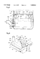
- FIG. 5 is a front view in vertical section of a muffler and adjacent components.
- FIG. 6 is a perspective view of the muffler and adjacent components.
- FIG. 1 shows a mid-mount type riding lawn tractor having a mower 7 suspended from a tractor body 1 between front and rear wheels 2 and 3.
- This riding lawn tractor includes an engine hood 4 disposed on a forward portion thereof and housing a vertical engine 5 with an output shaft extending downward.
- the engine 5 has an output pulley for transmitting drive through a belt transmission 6 to the mower 7.
- the mower 7 is vertically movably attached to body frames 1A through a link mechanism 8 raised and lowered by operating a hand lever 9.
- the engine hood 4 houses the engine 5 which is water-cooled and has a horizontal radiator 11 and a radiator cooling fan 12 arranged in an upper position.
- a battery 13 is mounted rearwardly of the engine 5, while an air cleaner 14, a carburetor 15 and a muffler 16 are arranged forwardly of the engine 5.
- a box-shaped dust netting 19 is disposed above the radiator 11.
- a fan cover 20 extends forward from a space between the radiator 11 and engine 5. The fan cover 20 substantially covers the cooling fan 12 in combination with a lower surface of the radiator 11 and an upper surface of the engine 5, and acts as an exhaust guide for forwardly exhausting cooling air delivered from the cooling fan 12.
- a shield 21 is connected to a bottom of the dust netting 19 to cover side surfaces of the radiator 11 and fan cover 20. Further, a heat shielding plate 22 straddles, and is fixedly connected to, an upper forward surface of the dust netting 19.
- a shield 26 is provided between the engine 5 and battery 13 for guiding radiator cooling air drawn in through intake openings 17a and 17b formed in a rear grille and side grilles constituting a control panel 17, to a rear bulge of the dust netting 19.
- This shield 26, hood 4 and control panel 17 define an intake air guide for guiding the cooling air from outside to the radiator 11.
- Trims 21a and 22a acting as seals are secured to a lower end of the shield 21 and an outer periphery of the heat shielding plate 22, respectively. Further, cushion elements 25 are arranged between the bottom of the dust netting 19 and the upper surface of the radiator 11 for preventing entry of hot air and suppressing noise.
- the box-shaped dust netting 19 is connected to the radiator i 1 through elastic engaging pieces 23 formed of plate springs and arranged in front and rear and fight and left positions of the radiator 11, and bent pieces 24 formed by bending edges of an opening in the bottom of the dust netting 19.
- the fan cover 20 is a box-shaped cover defining an intake opening 20a in the upper surface, and an exhaust opening 20b in the front surface.
- the fan cover 20 also defines an exhaust opening 20c in the lower surface thereof.
- the lower surface includes a scoop 20d for allowing cooling air to flow at an appropriate rate out of the exhaust opening 20c.
- the engine 5 is a V-type 2-cylinder engine, and exhaust gases from combustion chambers in the respective cylinders are guided to the muffler 16 through exhaust pipes 27 arranged at opposite sides of the engine 5.
- Ducts 28 are provided at opposite sides of a forward portion of the fan cover 20, whereby the cooling air discharged from regions at opposite sides of the exhaust opening 20b in the front surface of the fan cover 20 is guided toward the muffler 16 and directed to connections between the muffler 16 and exhaust pipes 27.
- the muffler 16 extends transversely of the tractor body inside a bumper frame 1B, U-shaped in plan view, interconnecting forward ends of right and left body frames 1A.
- the muffler 16 directs the exhaust gas laterally outwardly of the tractor body, and is covered by a muffler cover 29 formed of an upper cover 29A and a lower cover 29B fixed to the bumper frame 1B.
- the upper cover 29A has an upper surface and right and left side surfaces. The right and left side surfaces extend further rearward than the upper surface.
- the lower cover 29B has a lower surface and right and left side surfaces. The lower surface defines four exhaust openings 29a.
- the muffler 16 includes a muffler body 16A and an exhaust pipe 16B.
- the exhaust pipe 16B is attached to an exhaust opening 29b formed in a side surface of the lower cover 29B.
- the muffler body 16A has an outlet pipe 16a extending into the exhaust pipe 16B with a space 50 therebetween.
- the heat in the muffler cover 29 is released outside the tractor body by ejector action of exhaust gas flows.
- the exhaust pipe 16B is bent upward to direct the exhaust gas flows clear of dead leaves and the like collected on the ground.
- a rear muffler cover 29C is disposed rearwardly of the muffler body 16A and bolted to the bumper frame 1B to prevent the heat of the muffler 16 from being applied to an ignition coil 30 of the engine 5.
- the radiator cooling air having cooled the area adjacent the exhaust pipes 27 is thereby guided downward to flow out through the exhaust opening 29b.
- Perforated metal sheets 31 are provided for the exhaust openings 29a of the lower cover 29B to avoid a direct contact between dead leaves and the muffler body 16A.
- the cooling fan 12 draws cooling air through the intake openings 17a and 17b formed in the control panel 17 and gaps between an upper hood 4A and a lower hood 4B.
- the air stripped of dust by the dust netting 19 cools the radiator 11.
- a large part of the cooling air flows downward and forward through the fan cover 20, and flows forward and out through exhaust openings 4a in the front surface of the hood 4.
- a small part of the cooling air is guided by the ducts 28 to flow to the muffler 16, and out through the exhaust openings 29a formed in the lower surface of the muffler cover 29B.
- the cooling air guided into the right and left ducts 28 is directed to the connections between the muffler 16 and exhaust pipes 27, thereby to cool efficiently the hottest regions including the connections between the muffler 16 and exhaust pipes 27.
- the cooling air passing through the openings 20c in the lower surface of the fan cover 20 flows past the carburetor 15, and reaches exposed portions of the exhaust pipes 27 and the upper cover 29A of the muffler cover 29.
- the cooling air entering the muffler cover 29 cools the muffler 16, and then flows out through the exhaust opening 29b of the lower cover 29B of the muffler cover 29.
- the above embodiment has been described in relation to the muffler structure for the two-cylinder engine having two exhaust pipes.
- the invention is applicable also to a two-cylinder engine in which exhaust gases from respective cylinder chambers are transmitted through an exhaust manifold and a single exhaust pipe to a muffler. In this case, only one duct 28 may be adequate.
Abstract
Description
Claims (20)
Applications Claiming Priority (6)
| Application Number | Priority Date | Filing Date | Title |
|---|---|---|---|
| JP7111295A JPH08260963A (en) | 1995-03-29 | 1995-03-29 | Cooling air feeding structure of working vehicle |
| JP7-71112 | 1995-03-29 | ||
| JP7-228755 | 1995-09-06 | ||
| JP7-228756 | 1995-09-06 | ||
| JP22875595A JPH0972216A (en) | 1995-09-06 | 1995-09-06 | Work-car |
| JP22875695A JPH0972217A (en) | 1995-09-06 | 1995-09-06 | Work-car |
Publications (1)
| Publication Number | Publication Date |
|---|---|
| US5689953A true US5689953A (en) | 1997-11-25 |
Family
ID=27300547
Family Applications (1)
| Application Number | Title | Priority Date | Filing Date |
|---|---|---|---|
| US08/623,561 Expired - Lifetime US5689953A (en) | 1995-03-29 | 1996-03-28 | Cooling system for a liquid-cooled engine |
Country Status (1)
| Country | Link |
|---|---|
| US (1) | US5689953A (en) |
Cited By (50)
| Publication number | Priority date | Publication date | Assignee | Title |
|---|---|---|---|---|
| US5887671A (en) * | 1996-09-06 | 1999-03-30 | Kubota Corporation | Working vehicle with power steering |
| US6026768A (en) * | 1998-09-30 | 2000-02-22 | Honda Giken Kogyo Kabushiki Kaisha | Heat deflection system for a lawn tractor |
| US6035955A (en) * | 1995-08-25 | 2000-03-14 | Toyota Jidosha Kabushiki Kaisha | Engine compartment structure of a vehicle for introducing cool intake air |
| US6059061A (en) * | 1998-07-22 | 2000-05-09 | Economoff; Peter P. | Air cooling of vehicle radiators |
| US6167976B1 (en) * | 1998-07-30 | 2001-01-02 | Deere & Company | Engine enclosure |
| US6202777B1 (en) * | 1999-05-21 | 2001-03-20 | Deere & Company | Engine enclosure with cooling air baffle |
| US6216778B1 (en) * | 1998-12-30 | 2001-04-17 | Case Corporation | Cooling system for an off-highway vehicle |
| US6302066B1 (en) * | 1999-04-30 | 2001-10-16 | Caterpillar Inc. | Apparatus and method of cooling a work machine |
| US6431299B1 (en) | 2000-04-05 | 2002-08-13 | Clark Equipment Company | Cooling air ducting for excavator |
| US6435144B1 (en) | 1999-11-02 | 2002-08-20 | Caterpillar Inc. | Fan control system and method for simultaneous heat transfer application and engine enclosure ventilation |
| US6589307B2 (en) | 2000-12-13 | 2003-07-08 | Deere & Company | Intake screen for a vehicle |
| US6823955B2 (en) * | 2001-06-27 | 2004-11-30 | Deere & Company | 360 degree air intake screen |
| US6837324B2 (en) * | 2001-09-21 | 2005-01-04 | Kubota Corporation | Engine enclosure |
| US20050006048A1 (en) * | 2003-07-11 | 2005-01-13 | Deere & Company, A Delaware Corporation | Vertical airflow engine cooling system |
| US20050217907A1 (en) * | 2004-04-02 | 2005-10-06 | Madson Ricky D | Vehicle cooling package |
| US20050257972A1 (en) * | 2004-05-24 | 2005-11-24 | Kazuaki Iwami | Small-sized vehicle |
| US6968916B2 (en) * | 2000-11-03 | 2005-11-29 | Arctic Cat Inc. | Air intake system for a vehicle |
| US20070169989A1 (en) * | 2006-01-20 | 2007-07-26 | Commercial Turf Products, Ltd. | Cooling system for liquid-cooled machines |
| US20070215404A1 (en) * | 2006-03-16 | 2007-09-20 | Kwang Yang Motor Co., Ltd. | Cooling structure for a continuous variation transmission system of an all-terrain vehicle |
| US20070289570A1 (en) * | 2006-06-17 | 2007-12-20 | Agco Gmbh | Air guide in vehicle engine bay |
| US20090056651A1 (en) * | 2007-08-28 | 2009-03-05 | Caterpillar Paving Products | Machine having cooling system and method |
| US20090139473A1 (en) * | 2007-12-04 | 2009-06-04 | Mcmillan George Erik | Engine fluid cooler |
| US20100089674A1 (en) * | 2005-08-29 | 2010-04-15 | Yanmar Co., Ltd. | Tractor |
| DE102009023771A1 (en) * | 2009-06-03 | 2010-12-09 | Claas Selbstfahrende Erntemaschinen Gmbh | Self-driven harvesting machine i.e. combine harvester, has three radiator elements that are arranged within upper-lateral region of machine in horizontally aligned manner, where radiator elements guide cooling air flow in vertical direction |
| US20110259012A1 (en) * | 2010-04-27 | 2011-10-27 | Kubota Corporation | Working vehicle |
| WO2011080561A3 (en) * | 2009-12-30 | 2011-11-24 | Agco Corporation | Agricultural vehicle cooling assembly fan shroud with seals for pass-through cooling and exhaust tubes |
| US20120048631A1 (en) * | 2010-08-26 | 2012-03-01 | Caterpillar Inc. | Ventilation system for engine and aftertreatment compartments and components |
| US20120055729A1 (en) * | 2010-09-02 | 2012-03-08 | Kubota Corporation | Work Vehicle having Engine and Belt-Type Continuously Variable Transmission Device |
| US20120138379A1 (en) * | 2010-08-02 | 2012-06-07 | Komatsu Ltd. | Work vehicle |
| US20120186894A1 (en) * | 2011-01-25 | 2012-07-26 | Joseph Vogele Ag | Exhaust gas system for a building machine |
| US20130087402A1 (en) * | 2011-10-05 | 2013-04-11 | Kawasaki Jukogyo Kabushiki Kaisha | Utility Vehicle |
| US20130319778A1 (en) * | 2012-05-29 | 2013-12-05 | Don MacGregor | Windrower Tractor with Parallel Heat Exchangers for Cooling of Engine and Associated Fluids |
| US20140345833A1 (en) * | 2013-05-27 | 2014-11-27 | Hyundai Motor Company | Undercover for vehicle |
| CN104302500A (en) * | 2014-03-31 | 2015-01-21 | 株式会社小松制作所 | Work vehicle |
| US8967319B2 (en) | 2012-11-05 | 2015-03-03 | Cnh Industrial America Llc | Horizontal muffler for an agricultural vehicle |
| US20150101320A1 (en) * | 2013-10-15 | 2015-04-16 | Kobelco Construction Machinery Co., Ltd. | Gas release apparatus for construction machine |
| US20160046182A1 (en) * | 2014-08-14 | 2016-02-18 | Cnh Industrial America Llc | Exhaust system for an off-road vehicle |
| CN106246331A (en) * | 2015-06-11 | 2016-12-21 | 劳士领汽车集团 | Can the choke apparatus of audit function |
| US20170218808A1 (en) * | 2014-10-15 | 2017-08-03 | Yanmar Co., Ltd. | Work vehicle |
| US20170271942A1 (en) * | 2016-03-16 | 2017-09-21 | Honda Motor Co., Ltd. | Engine-driven working machine |
| US10030570B1 (en) * | 2017-05-16 | 2018-07-24 | Kubota Corporation | Work vehicle |
| US10036303B2 (en) * | 2016-09-02 | 2018-07-31 | Kubota Corporation | Lawn mower |
| US10196966B2 (en) * | 2016-12-15 | 2019-02-05 | Caterpillar Inc. | Modular power unit |
| US10688861B1 (en) * | 2019-03-19 | 2020-06-23 | Cnh Industrial America Llc | Engine airflow adjustment system |
| WO2020226486A1 (en) * | 2019-05-08 | 2020-11-12 | Rior, Industrie- En Handelsonderneming B.V. | Service engine with exhaust cooling |
| CN112177750A (en) * | 2020-09-30 | 2021-01-05 | 江苏徐工工程机械研究院有限公司 | Engineering vehicle cooling system with exhaust injection cooling device |
| US20210155172A1 (en) * | 2019-11-27 | 2021-05-27 | Yamaha Hatsudoki Kabushiki Kaisha | Vehicle |
| US11384689B2 (en) * | 2018-06-29 | 2022-07-12 | Cnh Industrial America Llc | Shielding assembly for debris management |
| US11732634B1 (en) * | 2022-05-25 | 2023-08-22 | Kawasaki Motors, Ltd. | Engine |
| US11927121B1 (en) * | 2022-09-08 | 2024-03-12 | Arctic Cat Inc. | Muffler assemblies for snowmobiles |
Citations (16)
| Publication number | Priority date | Publication date | Assignee | Title |
|---|---|---|---|---|
| US2121319A (en) * | 1936-05-04 | 1938-06-21 | Fluor Corp | Air-cooled muffler |
| US3949726A (en) * | 1974-04-03 | 1976-04-13 | Hans List | Internal combustion engine with encasing |
| US4265332A (en) * | 1979-06-21 | 1981-05-05 | Fmc Corporation | Heat extracting muffler system |
| US4706615A (en) * | 1985-05-09 | 1987-11-17 | Ford Motor Company | Engine cooling system |
| US4766983A (en) * | 1985-09-02 | 1988-08-30 | Kawasaki Jukogyo Kabushiki Kaisha | Muffler for V-type engine |
| US4862981A (en) * | 1984-12-24 | 1989-09-05 | Kawasaki Jukogyo Kabushiki Kaisha | Internal combustion engine and devices employing same |
| US4891940A (en) * | 1986-11-20 | 1990-01-09 | Kawasaki Jukogyo Kabushiki Kaisha | Muffler cooling structure for liquid-cooled engine system |
| US4903485A (en) * | 1987-12-10 | 1990-02-27 | Kawasaki Jukugyo Kabushiki Kaisha | Muffler cooling device for V-type engine |
| US5029668A (en) * | 1988-10-06 | 1991-07-09 | Kubota Ltd. | Muffler system |
| US5036931A (en) * | 1988-10-07 | 1991-08-06 | Kubota, Ltd. | Cooling system for engine mounted on vehicle |
| US5086858A (en) * | 1990-08-17 | 1992-02-11 | Kawasaki Jukogyo Kabushiki Kaisha | Air intake system for utility vehicle |
| US5113819A (en) * | 1990-07-04 | 1992-05-19 | Kubota Corporation | Cooling system for a liquid cooled engine |
| US5174406A (en) * | 1991-08-01 | 1992-12-29 | Deere & Company | Engine air deflector |
| US5199521A (en) * | 1990-07-18 | 1993-04-06 | Kubota Corporation | Lawn mower having passages for engine cooling air |
| US5207187A (en) * | 1990-07-04 | 1993-05-04 | Kubota Corporation | Air cooling system for a vertical engine |
| US5284115A (en) * | 1992-09-08 | 1994-02-08 | Kubota Corporation | Cooling system for a working vehicle |
-
1996
- 1996-03-28 US US08/623,561 patent/US5689953A/en not_active Expired - Lifetime
Patent Citations (16)
| Publication number | Priority date | Publication date | Assignee | Title |
|---|---|---|---|---|
| US2121319A (en) * | 1936-05-04 | 1938-06-21 | Fluor Corp | Air-cooled muffler |
| US3949726A (en) * | 1974-04-03 | 1976-04-13 | Hans List | Internal combustion engine with encasing |
| US4265332A (en) * | 1979-06-21 | 1981-05-05 | Fmc Corporation | Heat extracting muffler system |
| US4862981A (en) * | 1984-12-24 | 1989-09-05 | Kawasaki Jukogyo Kabushiki Kaisha | Internal combustion engine and devices employing same |
| US4706615A (en) * | 1985-05-09 | 1987-11-17 | Ford Motor Company | Engine cooling system |
| US4766983A (en) * | 1985-09-02 | 1988-08-30 | Kawasaki Jukogyo Kabushiki Kaisha | Muffler for V-type engine |
| US4891940A (en) * | 1986-11-20 | 1990-01-09 | Kawasaki Jukogyo Kabushiki Kaisha | Muffler cooling structure for liquid-cooled engine system |
| US4903485A (en) * | 1987-12-10 | 1990-02-27 | Kawasaki Jukugyo Kabushiki Kaisha | Muffler cooling device for V-type engine |
| US5029668A (en) * | 1988-10-06 | 1991-07-09 | Kubota Ltd. | Muffler system |
| US5036931A (en) * | 1988-10-07 | 1991-08-06 | Kubota, Ltd. | Cooling system for engine mounted on vehicle |
| US5113819A (en) * | 1990-07-04 | 1992-05-19 | Kubota Corporation | Cooling system for a liquid cooled engine |
| US5207187A (en) * | 1990-07-04 | 1993-05-04 | Kubota Corporation | Air cooling system for a vertical engine |
| US5199521A (en) * | 1990-07-18 | 1993-04-06 | Kubota Corporation | Lawn mower having passages for engine cooling air |
| US5086858A (en) * | 1990-08-17 | 1992-02-11 | Kawasaki Jukogyo Kabushiki Kaisha | Air intake system for utility vehicle |
| US5174406A (en) * | 1991-08-01 | 1992-12-29 | Deere & Company | Engine air deflector |
| US5284115A (en) * | 1992-09-08 | 1994-02-08 | Kubota Corporation | Cooling system for a working vehicle |
Cited By (76)
| Publication number | Priority date | Publication date | Assignee | Title |
|---|---|---|---|---|
| US6035955A (en) * | 1995-08-25 | 2000-03-14 | Toyota Jidosha Kabushiki Kaisha | Engine compartment structure of a vehicle for introducing cool intake air |
| US5887671A (en) * | 1996-09-06 | 1999-03-30 | Kubota Corporation | Working vehicle with power steering |
| US6059061A (en) * | 1998-07-22 | 2000-05-09 | Economoff; Peter P. | Air cooling of vehicle radiators |
| US6167976B1 (en) * | 1998-07-30 | 2001-01-02 | Deere & Company | Engine enclosure |
| US6026768A (en) * | 1998-09-30 | 2000-02-22 | Honda Giken Kogyo Kabushiki Kaisha | Heat deflection system for a lawn tractor |
| US6216778B1 (en) * | 1998-12-30 | 2001-04-17 | Case Corporation | Cooling system for an off-highway vehicle |
| US6302066B1 (en) * | 1999-04-30 | 2001-10-16 | Caterpillar Inc. | Apparatus and method of cooling a work machine |
| US6202777B1 (en) * | 1999-05-21 | 2001-03-20 | Deere & Company | Engine enclosure with cooling air baffle |
| US6435144B1 (en) | 1999-11-02 | 2002-08-20 | Caterpillar Inc. | Fan control system and method for simultaneous heat transfer application and engine enclosure ventilation |
| US6431299B1 (en) | 2000-04-05 | 2002-08-13 | Clark Equipment Company | Cooling air ducting for excavator |
| US6968916B2 (en) * | 2000-11-03 | 2005-11-29 | Arctic Cat Inc. | Air intake system for a vehicle |
| US6589307B2 (en) | 2000-12-13 | 2003-07-08 | Deere & Company | Intake screen for a vehicle |
| US6823955B2 (en) * | 2001-06-27 | 2004-11-30 | Deere & Company | 360 degree air intake screen |
| US6837324B2 (en) * | 2001-09-21 | 2005-01-04 | Kubota Corporation | Engine enclosure |
| US20050006048A1 (en) * | 2003-07-11 | 2005-01-13 | Deere & Company, A Delaware Corporation | Vertical airflow engine cooling system |
| US7051786B2 (en) * | 2003-07-11 | 2006-05-30 | Deere & Company | Vertical airflow engine cooling system |
| US20050217907A1 (en) * | 2004-04-02 | 2005-10-06 | Madson Ricky D | Vehicle cooling package |
| US7481287B2 (en) * | 2004-04-02 | 2009-01-27 | Deere & Company | Vehicle cooling package |
| US7216733B2 (en) * | 2004-05-24 | 2007-05-15 | Yamaha Hatsudoki Kabushiki Kaisha | Small-sized vehicle |
| US20050257972A1 (en) * | 2004-05-24 | 2005-11-24 | Kazuaki Iwami | Small-sized vehicle |
| US20100089674A1 (en) * | 2005-08-29 | 2010-04-15 | Yanmar Co., Ltd. | Tractor |
| US7320299B2 (en) | 2006-01-20 | 2008-01-22 | Commercial Turf Products, Ltd. | Cooling system for liquid-cooled machines |
| US20070169989A1 (en) * | 2006-01-20 | 2007-07-26 | Commercial Turf Products, Ltd. | Cooling system for liquid-cooled machines |
| US20070215404A1 (en) * | 2006-03-16 | 2007-09-20 | Kwang Yang Motor Co., Ltd. | Cooling structure for a continuous variation transmission system of an all-terrain vehicle |
| US7562739B2 (en) * | 2006-03-16 | 2009-07-21 | Kwang Yang Motor Co., Ltd. | Cooling structure for a continuous variation transmission system of an all-terrain vehicle |
| US20070289570A1 (en) * | 2006-06-17 | 2007-12-20 | Agco Gmbh | Air guide in vehicle engine bay |
| US7503306B2 (en) * | 2006-06-17 | 2009-03-17 | Agco Gmbh | Air guide in vehicle engine bay |
| US20090056651A1 (en) * | 2007-08-28 | 2009-03-05 | Caterpillar Paving Products | Machine having cooling system and method |
| US7931104B2 (en) | 2007-08-28 | 2011-04-26 | Caterpillar Paving Products Inc. | Machine having cooling system and method |
| US8267054B2 (en) * | 2007-12-04 | 2012-09-18 | Mcmillan George Erik | Engine fluid cooler |
| US20090139473A1 (en) * | 2007-12-04 | 2009-06-04 | Mcmillan George Erik | Engine fluid cooler |
| DE102009023771A1 (en) * | 2009-06-03 | 2010-12-09 | Claas Selbstfahrende Erntemaschinen Gmbh | Self-driven harvesting machine i.e. combine harvester, has three radiator elements that are arranged within upper-lateral region of machine in horizontally aligned manner, where radiator elements guide cooling air flow in vertical direction |
| WO2011080561A3 (en) * | 2009-12-30 | 2011-11-24 | Agco Corporation | Agricultural vehicle cooling assembly fan shroud with seals for pass-through cooling and exhaust tubes |
| US9476334B2 (en) * | 2010-04-27 | 2016-10-25 | Kubota Corporation | Working vehicle |
| US20110259012A1 (en) * | 2010-04-27 | 2011-10-27 | Kubota Corporation | Working vehicle |
| US20120138379A1 (en) * | 2010-08-02 | 2012-06-07 | Komatsu Ltd. | Work vehicle |
| US8505661B2 (en) * | 2010-08-02 | 2013-08-13 | Komatsu Ltd. | Work vehicle with engine compartment and exhaust gas treatment arrangement |
| US20120048631A1 (en) * | 2010-08-26 | 2012-03-01 | Caterpillar Inc. | Ventilation system for engine and aftertreatment compartments and components |
| US8919469B2 (en) * | 2010-08-26 | 2014-12-30 | Caterpillar Inc. | Ventilation system for engine and aftertreatment compartments and components |
| US8439141B2 (en) * | 2010-09-02 | 2013-05-14 | Kubota Corporation | Work vehicle having engine and belt-type continuously variable transmission device |
| US20120055729A1 (en) * | 2010-09-02 | 2012-03-08 | Kubota Corporation | Work Vehicle having Engine and Belt-Type Continuously Variable Transmission Device |
| US20120186894A1 (en) * | 2011-01-25 | 2012-07-26 | Joseph Vogele Ag | Exhaust gas system for a building machine |
| US8544582B2 (en) * | 2011-10-05 | 2013-10-01 | Kawasaki Jukogyo Kabushiki Kaisha | Utility vehicle |
| US20130087402A1 (en) * | 2011-10-05 | 2013-04-11 | Kawasaki Jukogyo Kabushiki Kaisha | Utility Vehicle |
| US20130319778A1 (en) * | 2012-05-29 | 2013-12-05 | Don MacGregor | Windrower Tractor with Parallel Heat Exchangers for Cooling of Engine and Associated Fluids |
| US8936122B2 (en) * | 2012-05-29 | 2015-01-20 | Macdon Industries Ltd. | Windrower tractor with parallel heat exchangers for cooling of engine and associated fluids |
| US8967319B2 (en) | 2012-11-05 | 2015-03-03 | Cnh Industrial America Llc | Horizontal muffler for an agricultural vehicle |
| US20140345833A1 (en) * | 2013-05-27 | 2014-11-27 | Hyundai Motor Company | Undercover for vehicle |
| US9359931B2 (en) * | 2013-10-15 | 2016-06-07 | Kobelco Construction Machinery Co., Ltd. | Gas release apparatus for construction machine |
| CN104564236B (en) * | 2013-10-15 | 2018-05-18 | 神钢建机株式会社 | The exhaust apparatus of engineering machinery |
| US20150101320A1 (en) * | 2013-10-15 | 2015-04-16 | Kobelco Construction Machinery Co., Ltd. | Gas release apparatus for construction machine |
| CN104564236A (en) * | 2013-10-15 | 2015-04-29 | 神钢建机株式会社 | Gas release apparatus for construction machine |
| CN104302500B (en) * | 2014-03-31 | 2018-02-02 | 株式会社小松制作所 | Working truck |
| US9353503B2 (en) | 2014-03-31 | 2016-05-31 | Komatsu Ltd. | Work vehicle |
| CN104302500A (en) * | 2014-03-31 | 2015-01-21 | 株式会社小松制作所 | Work vehicle |
| US9688134B2 (en) * | 2014-08-14 | 2017-06-27 | Cnh Industrial America Llc | Exhaust system for an off-road vehicle |
| US20160046182A1 (en) * | 2014-08-14 | 2016-02-18 | Cnh Industrial America Llc | Exhaust system for an off-road vehicle |
| US20170218808A1 (en) * | 2014-10-15 | 2017-08-03 | Yanmar Co., Ltd. | Work vehicle |
| US10487711B2 (en) * | 2014-10-15 | 2019-11-26 | Yanmar Co., Ltd. | Work vehicle |
| CN106246331A (en) * | 2015-06-11 | 2016-12-21 | 劳士领汽车集团 | Can the choke apparatus of audit function |
| CN106246331B (en) * | 2015-06-11 | 2019-09-13 | 劳士领汽车集团 | Can audit function choke apparatus |
| US10352227B2 (en) | 2015-06-11 | 2019-07-16 | Röchling Automotive SE & Co. KG | Flapper valve device with functional testing |
| US10224783B2 (en) * | 2016-03-16 | 2019-03-05 | Honda Motor Co., Ltd. | Engine-driven working machine |
| US20170271942A1 (en) * | 2016-03-16 | 2017-09-21 | Honda Motor Co., Ltd. | Engine-driven working machine |
| US10036303B2 (en) * | 2016-09-02 | 2018-07-31 | Kubota Corporation | Lawn mower |
| US10196966B2 (en) * | 2016-12-15 | 2019-02-05 | Caterpillar Inc. | Modular power unit |
| US10030570B1 (en) * | 2017-05-16 | 2018-07-24 | Kubota Corporation | Work vehicle |
| US11384689B2 (en) * | 2018-06-29 | 2022-07-12 | Cnh Industrial America Llc | Shielding assembly for debris management |
| US10688861B1 (en) * | 2019-03-19 | 2020-06-23 | Cnh Industrial America Llc | Engine airflow adjustment system |
| WO2020226486A1 (en) * | 2019-05-08 | 2020-11-12 | Rior, Industrie- En Handelsonderneming B.V. | Service engine with exhaust cooling |
| US11878638B2 (en) * | 2019-11-27 | 2024-01-23 | Yamaha Hatsudoki Kabushiki Kaisha | Vehicle |
| US20210155172A1 (en) * | 2019-11-27 | 2021-05-27 | Yamaha Hatsudoki Kabushiki Kaisha | Vehicle |
| CN112177750A (en) * | 2020-09-30 | 2021-01-05 | 江苏徐工工程机械研究院有限公司 | Engineering vehicle cooling system with exhaust injection cooling device |
| US11732634B1 (en) * | 2022-05-25 | 2023-08-22 | Kawasaki Motors, Ltd. | Engine |
| US11927121B1 (en) * | 2022-09-08 | 2024-03-12 | Arctic Cat Inc. | Muffler assemblies for snowmobiles |
| US20240084726A1 (en) * | 2022-09-08 | 2024-03-14 | Arctic Cat Inc. | Muffler Assemblies for Snowmobiles |
Similar Documents
| Publication | Publication Date | Title |
|---|---|---|
| US5689953A (en) | Cooling system for a liquid-cooled engine | |
| US5678648A (en) | Working vehicle | |
| US5207187A (en) | Air cooling system for a vertical engine | |
| AU2012202045B2 (en) | Tractor hood airflow system | |
| US4133547A (en) | Engine componentry | |
| US5036931A (en) | Cooling system for engine mounted on vehicle | |
| US5284115A (en) | Cooling system for a working vehicle | |
| US4382481A (en) | Dual fan engine cooling system | |
| US4371047A (en) | Agricultural tractor having reverse air flow cooling | |
| US4940100A (en) | Motor vehicle | |
| CA2074611C (en) | Engine air deflector | |
| US6026768A (en) | Heat deflection system for a lawn tractor | |
| US4455971A (en) | Water-cooled internal combustion engine with a sound absorbing cover | |
| JP2003326981A (en) | Engine arrangement structure for vehicle | |
| JPH0377371B2 (en) | ||
| KR940000036B1 (en) | Engine cooling structure for agriculture tractor | |
| US4917201A (en) | Motor vehicle | |
| US4726326A (en) | Drag reducing cooling system for a vehicle | |
| JPS63270228A (en) | Cooling and exhausting structure for vehicle | |
| JPH06257524A (en) | Intake air manifold supporting construction of transversely-mounted engine | |
| JP2868610B2 (en) | Work vehicle muffler cooling structure | |
| JPH064030Y2 (en) | External air introduction duct structure for intercooler cooling | |
| JPH0972217A (en) | Work-car | |
| JPH0281717A (en) | Cooling device for engine | |
| JP3177717B2 (en) | Combine engine equipment |
Legal Events
| Date | Code | Title | Description |
|---|---|---|---|
| AS | Assignment |
Owner name: KUBOTA CORPORATION, JAPAN Free format text: ASSIGNMENT OF ASSIGNORS INTEREST;ASSIGNORS:YAMASHITA, NOBUYUKI;IMANISHI, RYOZO;HAYASHI, MASAKI;AND OTHERS;REEL/FRAME:007947/0915 Effective date: 19960315 |
|
| STCF | Information on status: patent grant |
Free format text: PATENTED CASE |
|
| FPAY | Fee payment |
Year of fee payment: 4 |
|
| FEPP | Fee payment procedure |
Free format text: PAYOR NUMBER ASSIGNED (ORIGINAL EVENT CODE: ASPN); ENTITY STATUS OF PATENT OWNER: LARGE ENTITY |
|
| FPAY | Fee payment |
Year of fee payment: 8 |
|
| FPAY | Fee payment |
Year of fee payment: 12 |