US5691832A - Coherence multiplexed transmission system - Google Patents
Coherence multiplexed transmission system Download PDFInfo
- Publication number
- US5691832A US5691832A US08/283,448 US28344894A US5691832A US 5691832 A US5691832 A US 5691832A US 28344894 A US28344894 A US 28344894A US 5691832 A US5691832 A US 5691832A
- Authority
- US
- United States
- Prior art keywords
- signal
- modulator
- transmitter
- output
- autocorrelation function
- Prior art date
- Legal status (The legal status is an assumption and is not a legal conclusion. Google has not performed a legal analysis and makes no representation as to the accuracy of the status listed.)
- Expired - Fee Related
Links
Images


Classifications
-
- H—ELECTRICITY
- H04—ELECTRIC COMMUNICATION TECHNIQUE
- H04J—MULTIPLEX COMMUNICATION
- H04J3/00—Time-division multiplex systems
-
- H—ELECTRICITY
- H04—ELECTRIC COMMUNICATION TECHNIQUE
- H04J—MULTIPLEX COMMUNICATION
- H04J14/00—Optical multiplex systems
- H04J14/08—Time-division multiplex systems
-
- H—ELECTRICITY
- H04—ELECTRIC COMMUNICATION TECHNIQUE
- H04J—MULTIPLEX COMMUNICATION
- H04J14/00—Optical multiplex systems
- H04J14/002—Coherencemultiplexing
Definitions
- the invention relates to a multiplex transmission system comprising a transmitter which includes a signal source coupled to a first and a second modulator for respectively modulating a first and a second autocorrelation function value of an output signal on an output of the transmitter in response to a first and a second modulation signal respectively.
- the output of the transmitter is coupled via a channel to an input of a receiver, the receiver comprising correlation means for determining the modulation in at least one autocorrelation function value.
- the invention likewise relates to a transmitter to be used in such a transmission system.
- a transmission system as defined in the opening paragraph is known from the published article entitled: "Analysis of Optical Crosstalk in Coherence Multiplexed Systems Employing a Short Coherence Laser Diode with Arbitrary Power Spectrum", by J. P. Goedgebuer et al. in IEEE Journal of Quantum Electronics, Vol. 26, No. 7, July 1990.
- multiplex transmission systems it is desired to send several signals over a single transmission channel.
- the, transmit signals are to be combined into a single signal in one way or another.
- Various techniques to this end are known, such as time-division multiplexing and frequency-division multiplexing.
- samples of the different transmit signals or dam symbols of the different transmit signals are alternately applied to the channel.
- the rate at which the combined signal is applied to the channel be at least equal to the sum of the rates at which the individual signals are applied to the transmitter.
- each signal to be transmitted is individually modulated on its own carrier.
- a sum signal obtained by adding together all the carriers to a combined signal is then transmitted over the channel.
- the receiver then needs to comprise filters to recover the separate modulated carriers from the combined signal.
- the autocorrelation function of a signal supplied by a signal source is modulated by a modulator in response to the modulation signals.
- the autocorrelation function value of the transmitter output signal is modulated thereby for a delay belonging to that specific modulation signal.
- the correlation means in the receiver separates the different modulation signals by determining the autocorrelation function of the received signal for a delay period belonging to the appropriate modulation signal concerned.
- the modulator in the transmitter is generally arranged as an element which adds a delayed fraction of the signal source output signal, delayed over a period of time belonging to the modulation signal, to the transmitter output signal in response to the modulation signal concerned.
- the signal received at the input of the receiver strongly depends on the channel properties, the autocorrelation function of that input signal proves to change only slightly. As the channel properties now barely have a further effect on that function of the received signal, high transmission rates are possible. In TDM and FDM systems the transmission capacity is restricted by the channel properties.
- the delays used must satisfy a number of requirements in order to avoid cross talk between various modulation signals.
- This cross talk arises from the fact that the autocorrelation function of the signal source output signal has periodic components. This occurs, for example, in optical transmission systems in which a Fabry-Perot laser is used which generates a spectrum constituted by a number of equidistant discrete components.
- Another restriction of the transmission capacity may arise from the fact that the autocorrelation function of the signal source output signal shows a wide peak for a near zero delay value. This is found, for example, in optical transmission systems in which a DFB (Distributed FeedBack) laser is used which generates only a single spectral component. Due to the large width of the autocorrelation pulse around the zero value, the difference between the various delays in the various modulators must always be large to avoid cross talk. This again leads to another restriction of the attainable transmission capacity.
- DFB Distributed FeedBack
- the invention is characterized in that the transmitter comprises a decorrelation modulator for modulating the signal source output signal so as to reduce the autocorrelation function of the signal source output signal for non-zero delays.
- an autocorrelation function having a number of equidistant components is altered to such extent that the equidistant components for non-zero delays are attenuated considerably.
- the coherence between the signal source output signal is altered at different instants, so that the autocorrelation peak around zero will become narrower.
- the transmission capacity of the transmission system is increased considerably.
- the decorrelation modulator can be arranged as a separate modulator which drives the signal source, but it is alternatively conceivable that the decorrelation modulator is integrated in the signal source. This integration takes place, for example, in an autopulsating laser which generates a light signal formed by successive light pulses.
- a laser of this type is known, for example, from British Patent specification GB 2221 094 A.
- An embodiment of the invention is characterized in that the decorrelation modulator comprises an amplitude modulator.
- Amplitude modulation can easily be effected in most signal sources, so that the complexity of the transmission system is hardly enhanced by the addition of the decorrelation modulator.
- a further embodiment of the invention is characterized in that the transmitter comprises a pulse generator coupled to a modulation input of the decorrelation modulator.
- the use of a pulse generator is advantageous in that a large number of digital signals can be multiplexed, while each of the bit streams applied to the modulators only needs to have a bit rate equal to the pulse rate. This means that a high transmission rate of the whole transmission system can be attained without the need for generating signals having a very high frequency.
- the operation of the pulse generator can be approximated by a signal source having a more or less sine-shaped output signal, the signal source being switched off during the negative period and is switched on during the positive period.
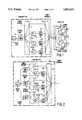
- FIG. 1 shows a transmission system according to the invention
- FIG. 2 shows a first alternative embodiment for the transmitter to be used in a transmission system as shown in FIG. 1;
- FIG. 3 shows a second alternative embodiment for the transmitter to be used in a transmission system as shown in FIG. 1;
- FIG. 4 shows a receiver to be used in a transmission system according to the invention
- FIG. 5 shows a passive optical distribution network implementing the invention
- FIG. 6 shows an autocorrelation function of the output signal of a Fabry-Perot laser as this is used in a state-of-the-art transmission system
- FIG. 7 shown an autocorrelation function of the output signal of a Fabry-Perot laser used in a transmission system according to the invention.
- a transmitter 2 is coupled to a receiver 6 by a channel in this case formed by a glass fibre.
- the output of a pulse generator 8 is coupled to an input of a decorrelation modulator 10, which is arranged for modulating a signal source, in this case formed by a semiconductor laser 1.
- the optical output of the semiconductor laser 1 is connected to an input of a power divider 12.
- a first output of the power divider 12 is connected to a first input of a power combiner 26.
- a second output of the power divider 12 is connected to an optical delay element 14.
- the output of the optical delay element 14 is connected to an input of an optical modulator 20, while the output of the optical modulator 20 is connected to a second input of the power combiner 26.
- a modulation signal m 1 is applied to a modulation input of the optical modulator 20.
- a third output of the power divider 12 is connected to a third input of the power combiner 26 via an optical delay element 16 having an optical delay D 2 , and a modulator 27.
- a modulation signal m 2 is applied to a modulation input of the modulator 25.
- a fourth output of the power divider 12 is connected to a fourth input of the power combiner 26 via an optical delay element 18 and an optical modulator 24.
- a modulation input of the modulator 24 is supplied with a modulation signal m 3 .
- the output of the power combiner 26, likewise forming the output of the transmitter, is connected to a receiver 6 by a channel in this case being a glass fibre 4.
- the input of the receiver is connected to an input of a power divider 28.
- Each of the outputs of the power divider 28 is connected to an input of a demodulator 30, 32 and 34.
- On the output of the demodulator 30, 32 and 34 are available the demodulated signals m 1 ', m 2 ' and m 3 '.
- the semiconductor laser 1 is switched on and off in a pulsed manner by the decorrelation modulator 10 in the transmitter 2 in response to the output signal of pulse generator 8.
- the power divider 12 splits the light generated by the semiconductor laser 1 into four parts which may be equal, but may also be different.
- Three of the output signals are delayed by their own delay elements i.e. 14, 16 and 18, over a period of time equal to D 1 , D 2 and D 3 , respectively.
- These delayed signals are amplitude or phase modulated by modulators 20, 25 and 24 by their individual modulation signals i.e. m 1 , m 2 and m 3 .
- the modulated signals and a non-modulated signal are combined into a single output signal by the power combiner 26.
- This output signal has an autocorrelation function which shows peaks for delays of, for example, zero, D 1 , D 2 and D 3 .
- the height of the peaks for delays D 1 , D 2 and D 3 is determined by the respective modulation signals m 1 , m 2 and m 3 .
- the various autocorrelation peaks are switched on and off by the modulation signals.
- the positions of the various autocorrelation peaks are varied between two values by the modulation signals.
- the combined signal is transferred to the receiver over the glass fibre 4.
- the transferred pulses will become wider as a result of the dispersion, but the autocorrelation functions will remain substantially the same.
- the received signal is split into three parts by the power divider 28. Each of these parts is demodulated by its own demodulator.
- the demodulators 30, 32 and 34 determine the autocorrelation function of their input signals for delays equal to D 1 , D 2 and D 3 , respectively.
- the signals m 1 ', m 2 ' and m 3 ' are available on the outputs of the demodulators 30, 32 and 34.
- the peak of the autocorrelation function for a zero delay has a width of about 1/ ⁇ f.
- ⁇ can be expressed in ⁇ f:
- D is the dispersion of the glass fibre expressed in s/m 2 and L is the length of the glass fibre.
- the transmission capacity proves to be immune to the properties of the glass fibre.
- the number of delay elements N needed is then equal to ⁇ .B. This is taken to mean that the complexity of the transmission system enhances with the total dispersion of the glass fibre and with the transmission capacity.
- the output of a pulse generator 8 is connected to an input of each of decorrelation modulators 7, 9 and 11, which are arranged for modulating signal sources, here formed by semiconductor lasers 21, 22 and 23.
- the output of the semiconductor laser 21 is connected to an input of a power divider 13.
- a first output of the power divider 13 is connected to a first input of a power combiner 19, while a second output of the power divider 13 is connected to a second input of the power combiner 19 via an optical delay element 14 and an optical modulator 20.
- the output of the semiconductor laser 22 is connected to an input of a power divider 15.
- a first output of the power divider 15 is connected to a third input of the power combiner 19, while a second output of the power divider 15 is connected to a fourth input of the power combiner 19 via an optical delay element 16 and an optical modulator 25.
- the output of the semiconductor laser 23 is connected to a first input of a power divider 17.
- a first output of the power divider 17 is connected to a fifth input of the power combiner 19, while a second output of the power divider 17 is connected to a sixth input of the power combiner 19 via an optical delay element 18 and an optical modulator 24.
- the output of the transmitter 2 is formed by the output of the power combiner 19.
- each decorrelation modulator is driven by a separate pulse generator.
- the autocorrelation function of the output signal of transmitter 2 is modulated by the modulators 20, 25 and 24 in similar fashion to the transmitter shown in FIG. 1.
- the advantage of the use of more signal sources is that it will be sufficient to have signal sources which have a relatively small output power, because this output power needs to be sufficient for only a single modulation signal.
- the signal source in the transmitter shown in FIG. 1 will have to produce a considerable power that is N times larger than the power of one of the semiconductors 21, 22 or 23.
- the output of a pulse generator 8 is connected to an input of a decorrelation modulator 10 for modulating a semiconductor laser 1.
- the output of the semiconductor laser 1 is connected to an input of a power divider 30.
- a first output of the power divider 31 is connected to a first input of a power combiner 33.
- a second output of the power divider 31 is connected to a second input of the power combiner 33 via an optical delay element 14 and an optical modulator 20.
- An output of the power combiner 33 is connected to an input of a power divider 35.
- a first output of the power divider 35 is connected to a first input of a power combiner 36.
- a second output of the power divider 35 is connected to a second input of the power combiner 36 via an optical delay element 16 and an optical modulator 25.
- a modulation unit 38 which is structured similarly to the modulation units comprising a power combiner, a delay element, an optical modulator and a power combiner.
- the modulation units are cascaded, contrary to the transmitter shown in FIG. 1, in which the modulation units are connected in parallel.
- the use of power dividers having two outputs and power combiners having two inputs may suffice, whereas power dividers/combiners having larger numbers of inputs/outputs are necessary in the transmitter shown in FIG. 1.
- a disadvantage of the transmitter shown in FIG. 3 is the introduction of components into the autocorrelation function of the transmitter output signal for delays D 1 +D 2 , D 1 +D 3 , D 2 +D 3 and D 1 +D 2 +D 3 . These components cause cross talk to occur if the system uses delay elements for other modulation signals having one of these delays.
- the modulators in the transmitters can be arranged not only as amplitude modulators, but also as phase modulators modulating the position of the autocorrelation peak as a function of the modulation signal.
- the demodulators 30, 32, 34 shown in FIG. 1 are shown in more detail in FIG. 4, in which the signal to be demodulated is applied to an input of a power divider 40.
- a first output of the power divider 40 is connected to a first input of a 180° hybrid 46 via a delay element 42 comprising a piece of glass fibre having a defined length.
- a second output of the power divider 40 is connected to a second input of the 180° hybrid 46 via a phase shifter 44.
- a first output of the 180° hybrid 46 is connected to a photo diode 48 and a second output of the 180° hybrid 46 is connected to a photo diode 50.
- the output of the photo diode 48 is connected to a positive input of a differential amplifier 52, the output of the photo diode 50 being connected to a negative input of the differential amplifier 52.
- the output of the differential amplifier 52 likewise forming the output of the demodulator, is connected to a first input of a synchronous detector 60.
- An output of an auxiliary signal generator 54 is connected to a second input of the synchronous detector 60 and to a first input of an adder circuit 56.
- the output of the synchronous detector 60 is connected to an input of an integrator 58.
- the output of the integrator 58 is connected to a second input of the adder circuit 56.
- the output of the adder circuit 56 is connected to a control input of the phase shifter 44.
- the received signal is assumed to comprise a series of main pulses having a repetition rate of f r , and a series of signal-carrying pulses whose amplitude or exact position is determined by a modulation signal, the signal carrying the latter pulses being delayed by D 1 seconds relative to the main pulses.
- the delay difference in the two branches between the power divider 40 and the 180° hybrid is a multiple of the period belonging to the optical frequency (c/ ⁇ ) of the light signal.
- the incoming signal is split into two components.
- One of these components is subjected to a delay D 1 in the delay element 42. If this delay period is equal to the time difference between a main pulse and a signal-carrying pulse, the main pulse on the output of the delay element 42 will coincide with the signal-carrying pulse on the output of the phase shifter 44.
- the output signal on the first output of the 180° hybrid is equal to the sum of the two input signals of the 180° hybrid, and the output signal on the second output of the 180° hybrid is equal to the difference between the two input signals of the hybrid.
- amplitude modulation of the signal dash carrying pulses can be demodulated.
- phase modulation for example, 0 and 180° PSK
- the desired signal will be available only on the first output of the 180° hybrid 46 during the 0° period, whereas during a 180° period the desired signal will be available only on the second output of the hybrid. This results in the fact that the sign of the output signal of the amplifier 52 is determined by the phase of the modulated signal.
- phase rotation circuit 44 is supplied with an auxiliary signal generated by the auxiliary signal generator 54. This causes the phase difference between the output signals of the delay element 42 and the output of the phase rotation circuit 44 to vary.
- an error signal is obtained which is a measure for the deviation from the average phase difference between the output signals of the two branches of the demodulator.
- This error signal is integrated by the integrator 58.
- the output signal of the integrator 58 is applied, via the adder circuit, to the phase shifter to correct the average phase difference.
- a transmitter 62 is connected to a plurality of telephone connections 64 . . . 80 via a passive optical network.
- This passive optical network is partly a common network to a plurality of subscribers. Therefore, it is necessary that the receivers in the subscriber connections extract from the complete signal the signal intended for the subscriber concerned.
- the signals intended for the different subscribers are combined in the transmitter 62 by coherence multiplexing with different delays D 1 , . . . , D n to form a single output signal.
- Each of the subscriber receivers comprises a demodulator which has its own delay which, within the coherence time, is equal to one of the values D 1 -D n . As the demodulators of different subscribers are set to different values, each subscriber receives the signal intended for that subscriber.
- FIG. 6 the autocorrelation function is shown of the output signal of a Fabry-Perot laser of the CQF56 type supplied by Philips Semiconductors. The laser is then continuously switched on as in the state-of-the-art transmission system.
- FIG. 6 distinctly shows that the autocorrelation function has a large number of components due to which the use of such a signal source leads to a considerable limitation of the transmission capacity.
- FIG. 7 shows the autocorrelation of a CQF56 laser used in a transmission system according to the invention.
- the laser is pulse modulated (switched on and off) with the measurement of the autocorrelation function, which pulses have a 919 MHz frequency.
- the pulses are approximated here by a sine-shaped signal.
- the quiescent current flowing through the laser was here 3mA.
- FIG. 7 distinctly shows that the number of periodic components of the autocorrelation function are reduced considerably relative to the autocorrelation function shown in FIG. 6. As a result, smaller values of the delays D 1 , . . . , D n can be used, so that a higher transmission capacity can be achieved.
Abstract
In a transmitter in a coherence multiplexed transmission system the output signal of a laser is directly applied to a channel and indirectly via a plurality of cascaded circuits of delay elements and modulators. The modulators vary a component of the autocorrelation function of the output signal of the transmitter as a function of an associated modulation signal (m1, m2, m3). In the receiver the autocorrelation functions values of the channel output signal for delays (D1, D2, D3) are determined in the demodulators. These autocorrelation function values from the modulated signal (m1 ', m2 ', m3 '). To reduce the number of periodic components of the autocorrelation function of the signal source, and hence enhance the possible transmission capacity, the transmitter comprises a decorrelation modulator for modulating the signal source with pulses generated by a pulse generator.
Description
1. Field of the Invention
The invention relates to a multiplex transmission system comprising a transmitter which includes a signal source coupled to a first and a second modulator for respectively modulating a first and a second autocorrelation function value of an output signal on an output of the transmitter in response to a first and a second modulation signal respectively. The output of the transmitter is coupled via a channel to an input of a receiver, the receiver comprising correlation means for determining the modulation in at least one autocorrelation function value.
The invention likewise relates to a transmitter to be used in such a transmission system.
2. Description of the Related Art
A transmission system as defined in the opening paragraph is known from the published article entitled: "Analysis of Optical Crosstalk in Coherence Multiplexed Systems Employing a Short Coherence Laser Diode with Arbitrary Power Spectrum", by J. P. Goedgebuer et al. in IEEE Journal of Quantum Electronics, Vol. 26, No. 7, July 1990.
In multiplex transmission systems it is desired to send several signals over a single transmission channel. For this purpose, the, transmit signals are to be combined into a single signal in one way or another. Various techniques to this end are known, such as time-division multiplexing and frequency-division multiplexing.
In time-division multiplexing, samples of the different transmit signals or dam symbols of the different transmit signals are alternately applied to the channel. In this respect it is then necessary that the rate at which the combined signal is applied to the channel be at least equal to the sum of the rates at which the individual signals are applied to the transmitter.
When a large number of different signals are to be combined into a single time-division multiplex signal, a high processing rate is then required from the necessary electronic components, which leads to a substantial cost price of the system.
When frequency-division multiplex is used, each signal to be transmitted is individually modulated on its own carrier. A sum signal obtained by adding together all the carriers to a combined signal, is then transmitted over the channel. The receiver then needs to comprise filters to recover the separate modulated carriers from the combined signal. When there are a large number of signals, a large number of often complex filters are necessary.
In the transmission system known from said journal article, the autocorrelation function of a signal supplied by a signal source is modulated by a modulator in response to the modulation signals. For each of the modulation signals the autocorrelation function value of the transmitter output signal is modulated thereby for a delay belonging to that specific modulation signal.
The correlation means in the receiver separates the different modulation signals by determining the autocorrelation function of the received signal for a delay period belonging to the appropriate modulation signal concerned.
The modulator in the transmitter is generally arranged as an element which adds a delayed fraction of the signal source output signal, delayed over a period of time belonging to the modulation signal, to the transmitter output signal in response to the modulation signal concerned.
Although the signal received at the input of the receiver strongly depends on the channel properties, the autocorrelation function of that input signal proves to change only slightly. As the channel properties now barely have a further effect on that function of the received signal, high transmission rates are possible. In TDM and FDM systems the transmission capacity is restricted by the channel properties.
In the transmission system known from said journal article, the delays used must satisfy a number of requirements in order to avoid cross talk between various modulation signals. This cross talk arises from the fact that the autocorrelation function of the signal source output signal has periodic components. This occurs, for example, in optical transmission systems in which a Fabry-Perot laser is used which generates a spectrum constituted by a number of equidistant discrete components. These requirements, which are imposed by the periodicity in the autocorrelation function of the signal source, lead to a restriction of the number of usable values of the delay in the modulators.
Another restriction of the transmission capacity may arise from the fact that the autocorrelation function of the signal source output signal shows a wide peak for a near zero delay value. This is found, for example, in optical transmission systems in which a DFB (Distributed FeedBack) laser is used which generates only a single spectral component. Due to the large width of the autocorrelation pulse around the zero value, the difference between the various delays in the various modulators must always be large to avoid cross talk. This again leads to another restriction of the attainable transmission capacity.
It is an object of the invention to provide a transmission system as defined in the opening paragraph, in which said restrictions of the transmission capacity are eliminated.
For this purpose, the invention is characterized in that the transmitter comprises a decorrelation modulator for modulating the signal source output signal so as to reduce the autocorrelation function of the signal source output signal for non-zero delays.
By modulating the signal source by means of the decorrelation modulator, an autocorrelation function having a number of equidistant components is altered to such extent that the equidistant components for non-zero delays are attenuated considerably. In a signal source showing a wide autocorrelation peak around zero, the coherence between the signal source output signal is altered at different instants, so that the autocorrelation peak around zero will become narrower. In both situations the transmission capacity of the transmission system is increased considerably. The decorrelation modulator can be arranged as a separate modulator which drives the signal source, but it is alternatively conceivable that the decorrelation modulator is integrated in the signal source. This integration takes place, for example, in an autopulsating laser which generates a light signal formed by successive light pulses. A laser of this type is known, for example, from British Patent specification GB 2221 094 A.
It is observed that from U.S. Pat. No. 4,882,775 a transmission system is known which utilizes coherence multiplexing in which the signal source is modulated. In this transmission system the signal source is modulated in response to the modulation signal, however. However, an additional decorrelation modulator is not provided in the transmission system, so that the problem solved by the present invention is still present in the transmission system known from said U.S. Patent.
An embodiment of the invention is characterized in that the decorrelation modulator comprises an amplitude modulator.
Amplitude modulation can easily be effected in most signal sources, so that the complexity of the transmission system is hardly enhanced by the addition of the decorrelation modulator.
A further embodiment of the invention is characterized in that the transmitter comprises a pulse generator coupled to a modulation input of the decorrelation modulator.
The use of a pulse generator is advantageous in that a large number of digital signals can be multiplexed, while each of the bit streams applied to the modulators only needs to have a bit rate equal to the pulse rate. This means that a high transmission rate of the whole transmission system can be attained without the need for generating signals having a very high frequency. The operation of the pulse generator can be approximated by a signal source having a more or less sine-shaped output signal, the signal source being switched off during the negative period and is switched on during the positive period.
The invention will be further explained with reference to the drawings Figures, in which:
FIG. 1 shows a transmission system according to the invention;
FIG. 2 shows a first alternative embodiment for the transmitter to be used in a transmission system as shown in FIG. 1;
FIG. 3 shows a second alternative embodiment for the transmitter to be used in a transmission system as shown in FIG. 1;
FIG. 4 shows a receiver to be used in a transmission system according to the invention;
FIG. 5 shows a passive optical distribution network implementing the invention;
FIG. 6 shows an autocorrelation function of the output signal of a Fabry-Perot laser as this is used in a state-of-the-art transmission system; and
FIG. 7 shown an autocorrelation function of the output signal of a Fabry-Perot laser used in a transmission system according to the invention.
In the transmission system shown in FIG. 1 a transmitter 2 is coupled to a receiver 6 by a channel in this case formed by a glass fibre. In the transmitter 2 the output of a pulse generator 8 is coupled to an input of a decorrelation modulator 10, which is arranged for modulating a signal source, in this case formed by a semiconductor laser 1. The optical output of the semiconductor laser 1 is connected to an input of a power divider 12. A first output of the power divider 12 is connected to a first input of a power combiner 26. A second output of the power divider 12 is connected to an optical delay element 14. The output of the optical delay element 14 is connected to an input of an optical modulator 20, while the output of the optical modulator 20 is connected to a second input of the power combiner 26. A modulation signal m1 is applied to a modulation input of the optical modulator 20. A third output of the power divider 12 is connected to a third input of the power combiner 26 via an optical delay element 16 having an optical delay D2, and a modulator 27. A modulation signal m2 is applied to a modulation input of the modulator 25. A fourth output of the power divider 12 is connected to a fourth input of the power combiner 26 via an optical delay element 18 and an optical modulator 24. A modulation input of the modulator 24 is supplied with a modulation signal m3.
The output of the power combiner 26, likewise forming the output of the transmitter, is connected to a receiver 6 by a channel in this case being a glass fibre 4. The input of the receiver is connected to an input of a power divider 28. Each of the outputs of the power divider 28 is connected to an input of a demodulator 30, 32 and 34. On the output of the demodulator 30, 32 and 34 are available the demodulated signals m1 ', m2 ' and m3 '.
In the transmission system shown in FIG. 1 the semiconductor laser 1 is switched on and off in a pulsed manner by the decorrelation modulator 10 in the transmitter 2 in response to the output signal of pulse generator 8. The power divider 12 splits the light generated by the semiconductor laser 1 into four parts which may be equal, but may also be different. Three of the output signals are delayed by their own delay elements i.e. 14, 16 and 18, over a period of time equal to D1, D2 and D3, respectively. These delayed signals are amplitude or phase modulated by modulators 20, 25 and 24 by their individual modulation signals i.e. m1, m2 and m3. The modulated signals and a non-modulated signal are combined into a single output signal by the power combiner 26. This output signal has an autocorrelation function which shows peaks for delays of, for example, zero, D1, D2 and D3. The height of the peaks for delays D1, D2 and D3 is determined by the respective modulation signals m1, m2 and m3. When the amplitude of the signal source output signal is modulated in response to binary digital signals, the various autocorrelation peaks are switched on and off by the modulation signals. When the phase of the signal source output signal is modulated in response to binary digital signals, the positions of the various autocorrelation peaks are varied between two values by the modulation signals.
The combined signal is transferred to the receiver over the glass fibre 4. The transferred pulses will become wider as a result of the dispersion, but the autocorrelation functions will remain substantially the same. In the receiver 6 the received signal is split into three parts by the power divider 28. Each of these parts is demodulated by its own demodulator. The demodulators 30, 32 and 34 determine the autocorrelation function of their input signals for delays equal to D1, D2 and D3, respectively. The signals m1 ', m2 ' and m3 ' are available on the outputs of the demodulators 30, 32 and 34.
If the semiconductor laser 1 used generates a light signal having a Δf bandwidth, the peak of the autocorrelation function for a zero delay has a width of about 1/Δf. Assuming that c=λf, where c is the velocity of light, Δλ can be expressed in Δf:
Δλ=Δf·λ.sup.2 /C (1)
For the pulse widening Δτ due to dispersion holds: ##EQU1##
In (2) D is the dispersion of the glass fibre expressed in s/m2 and L is the length of the glass fibre. There is no cross talk as long as the pulse width at the output of the glass fibre is smaller than the period of the pulses. For the maximum value of the repetition rate fr of the pulse source it then holds: fr =1/Δτ. The minimum value of the difference between two delays is to exceed the width of the peaks of the autocorrelation function of the laser output signal. The following can then be written by approximation for the permissible minimum value of this difference:
Δt≈2/Δf (3)
The number of modulation signals N that can be accommodated in the system without this leading to cross talk is then equal to:
N=Δτ/Δt (4)
For the total transmission capacity it then holds: ##EQU2##
Thus the transmission capacity proves to be immune to the properties of the glass fibre. The number of delay elements N needed is then equal to Δτ.B. This is taken to mean that the complexity of the transmission system enhances with the total dispersion of the glass fibre and with the transmission capacity.
In the transmitter 2 shown in FIG. 2 the output of a pulse generator 8 is connected to an input of each of decorrelation modulators 7, 9 and 11, which are arranged for modulating signal sources, here formed by semiconductor lasers 21, 22 and 23.
The output of the semiconductor laser 21 is connected to an input of a power divider 13. A first output of the power divider 13 is connected to a first input of a power combiner 19, while a second output of the power divider 13 is connected to a second input of the power combiner 19 via an optical delay element 14 and an optical modulator 20.
The output of the semiconductor laser 22 is connected to an input of a power divider 15. A first output of the power divider 15 is connected to a third input of the power combiner 19, while a second output of the power divider 15 is connected to a fourth input of the power combiner 19 via an optical delay element 16 and an optical modulator 25. The output of the semiconductor laser 23 is connected to a first input of a power divider 17. A first output of the power divider 17 is connected to a fifth input of the power combiner 19, while a second output of the power divider 17 is connected to a sixth input of the power combiner 19 via an optical delay element 18 and an optical modulator 24.
The output of the transmitter 2 is formed by the output of the power combiner 19.
In the transmitter shown in FIG. 2 three signal sources are used instead of one. These signal sources are amplitude modulated by the decorrelation modulators 7, 9 and 11 in response to the output signal of the pulse generator 8. Needless to observe that it is conceivable that each decorrelation modulator is driven by a separate pulse generator. The autocorrelation function of the output signal of transmitter 2, for delays D1, D2 and D3, is modulated by the modulators 20, 25 and 24 in similar fashion to the transmitter shown in FIG. 1.
The advantage of the use of more signal sources is that it will be sufficient to have signal sources which have a relatively small output power, because this output power needs to be sufficient for only a single modulation signal. With a large N, the signal source in the transmitter shown in FIG. 1 will have to produce a considerable power that is N times larger than the power of one of the semiconductors 21, 22 or 23.
In the transmitter 2 shown in FIG. 3 the output of a pulse generator 8 is connected to an input of a decorrelation modulator 10 for modulating a semiconductor laser 1. The output of the semiconductor laser 1 is connected to an input of a power divider 30. A first output of the power divider 31 is connected to a first input of a power combiner 33. A second output of the power divider 31 is connected to a second input of the power combiner 33 via an optical delay element 14 and an optical modulator 20.
An output of the power combiner 33 is connected to an input of a power divider 35. A first output of the power divider 35 is connected to a first input of a power combiner 36. A second output of the power divider 35 is connected to a second input of the power combiner 36 via an optical delay element 16 and an optical modulator 25.
Between the output of the power combiner 36 and the output of the transmitter is included a modulation unit 38 which is structured similarly to the modulation units comprising a power combiner, a delay element, an optical modulator and a power combiner.
In the transmitter shown in FIG. 3 the modulation units are cascaded, contrary to the transmitter shown in FIG. 1, in which the modulation units are connected in parallel. In the transmitter shown in FIG. 3 the use of power dividers having two outputs and power combiners having two inputs may suffice, whereas power dividers/combiners having larger numbers of inputs/outputs are necessary in the transmitter shown in FIG. 1.
A disadvantage of the transmitter shown in FIG. 3 is the introduction of components into the autocorrelation function of the transmitter output signal for delays D1 +D2, D1 +D3, D2 +D3 and D1 +D2 +D3. These components cause cross talk to occur if the system uses delay elements for other modulation signals having one of these delays.
It is noted that the modulators in the transmitters can be arranged not only as amplitude modulators, but also as phase modulators modulating the position of the autocorrelation peak as a function of the modulation signal.
The demodulators 30, 32, 34 shown in FIG. 1 are shown in more detail in FIG. 4, in which the signal to be demodulated is applied to an input of a power divider 40. A first output of the power divider 40 is connected to a first input of a 180° hybrid 46 via a delay element 42 comprising a piece of glass fibre having a defined length. A second output of the power divider 40 is connected to a second input of the 180° hybrid 46 via a phase shifter 44. A first output of the 180° hybrid 46 is connected to a photo diode 48 and a second output of the 180° hybrid 46 is connected to a photo diode 50. The output of the photo diode 48 is connected to a positive input of a differential amplifier 52, the output of the photo diode 50 being connected to a negative input of the differential amplifier 52. The output of the differential amplifier 52, likewise forming the output of the demodulator, is connected to a first input of a synchronous detector 60. An output of an auxiliary signal generator 54 is connected to a second input of the synchronous detector 60 and to a first input of an adder circuit 56. The output of the synchronous detector 60 is connected to an input of an integrator 58. The output of the integrator 58 is connected to a second input of the adder circuit 56. The output of the adder circuit 56 is connected to a control input of the phase shifter 44.
For explanation of the operation of the demodulator in FIG. 4 the received signal is assumed to comprise a series of main pulses having a repetition rate of fr, and a series of signal-carrying pulses whose amplitude or exact position is determined by a modulation signal, the signal carrying the latter pulses being delayed by D1 seconds relative to the main pulses. In addition, it is assumed that the delay difference in the two branches between the power divider 40 and the 180° hybrid is a multiple of the period belonging to the optical frequency (c/λ) of the light signal.
In the power divider 40 the incoming signal is split into two components. One of these components is subjected to a delay D1 in the delay element 42. If this delay period is equal to the time difference between a main pulse and a signal-carrying pulse, the main pulse on the output of the delay element 42 will coincide with the signal-carrying pulse on the output of the phase shifter 44. The output signal on the first output of the 180° hybrid is equal to the sum of the two input signals of the 180° hybrid, and the output signal on the second output of the 180° hybrid is equal to the difference between the two input signals of the hybrid. As the delayed pulse of the first input of the 180° hybrid 46 and the main pulse on the second input of the 180° hybrid 46 coincide, constructive interference will cause a pulse to occur having a twice higher amplitude than on the first output of the 180° hybrid 46, whereas destructive interference will cause the absence of a signal on the second output of the 180° hybrid. The main pulse of the output signal of the phase shifter 44 will lead to two equally large pulses on the two outputs of the 180° hybrid 46. The same will hold for the delayed (signal carrying) pulse on the output of the delay element 42. On the output of the amplifier 52 a pulse will then only be available if the optical input signals on the inputs of the two photo diodes 48 and 50 are different. This is only the case when a main pulse of one branch coincides with a signal dash carrying pulse of the other branch.
In similar manner, amplitude modulation of the signal dash carrying pulses can be demodulated.
In the case of phase modulation (for example, 0 and 180° PSK) the desired signal will be available only on the first output of the 180° hybrid 46 during the 0° period, whereas during a 180° period the desired signal will be available only on the second output of the hybrid. This results in the fact that the sign of the output signal of the amplifier 52 is determined by the phase of the modulated signal.
If the difference between the delay D1 and the delay between a main pulse and a signal dash carrying pulse is larger than the coherence time, no interference effects will occur and the two output signals will be the same. This means that the output signal of the amplifier 52 will be equal to 0.
To provide that the delay difference between the two branches of the demodulator is exactly a multiple of the period belonging to the frequency of the light, there is a control system available formed by synchronous detector 60, integrator 58, adder circuit 56, auxiliary signal generator 54 and phase rotation circuit 44.
Via the adder circuit 56 the phase rotation circuit 44 is supplied with an auxiliary signal generated by the auxiliary signal generator 54. This causes the phase difference between the output signals of the delay element 42 and the output of the phase rotation circuit 44 to vary.
If the average phase difference between the output signals of the branches of the demodulator are equal to 0 (or π), the amplitude of the output signal of the differential amplifier is maximized. Since the output signal of the differential amplifier 52 presents an even symmetry around φ=0 (and π) as a function of the phase shift φ of the phase shifter 44, the variations of the phase difference will not lead to an auxiliary-signal-dependent signal component on the output of the differential amplifier 52.
If the average phase difference differs from 0 (or π), however, the variations of the phase difference do result in an auxiliary-signal-dependent signal component in the output signal of the differential amplifier 52.
By detecting the presence of the auxiliary-signal-dependent signal component in the output signal of the differential amplifier 52 with the aid of the synchronous detector 60, an error signal is obtained which is a measure for the deviation from the average phase difference between the output signals of the two branches of the demodulator. This error signal is integrated by the integrator 58. The output signal of the integrator 58 is applied, via the adder circuit, to the phase shifter to correct the average phase difference.
In the transmission system shown in FIG. 5 a transmitter 62 is connected to a plurality of telephone connections 64 . . . 80 via a passive optical network. This passive optical network is partly a common network to a plurality of subscribers. Therefore, it is necessary that the receivers in the subscriber connections extract from the complete signal the signal intended for the subscriber concerned. For this purpose, the signals intended for the different subscribers are combined in the transmitter 62 by coherence multiplexing with different delays D1, . . . , Dn to form a single output signal. Each of the subscriber receivers comprises a demodulator which has its own delay which, within the coherence time, is equal to one of the values D1 -Dn. As the demodulators of different subscribers are set to different values, each subscriber receives the signal intended for that subscriber.
In FIG. 6 the autocorrelation function is shown of the output signal of a Fabry-Perot laser of the CQF56 type supplied by Philips Semiconductors. The laser is then continuously switched on as in the state-of-the-art transmission system. FIG. 6 distinctly shows that the autocorrelation function has a large number of components due to which the use of such a signal source leads to a considerable limitation of the transmission capacity.
FIG. 7 shows the autocorrelation of a CQF56 laser used in a transmission system according to the invention. The laser is pulse modulated (switched on and off) with the measurement of the autocorrelation function, which pulses have a 919 MHz frequency. The pulses are approximated here by a sine-shaped signal. The quiescent current flowing through the laser was here 3mA. FIG. 7 distinctly shows that the number of periodic components of the autocorrelation function are reduced considerably relative to the autocorrelation function shown in FIG. 6. As a result, smaller values of the delays D1, . . . , Dn can be used, so that a higher transmission capacity can be achieved.
Claims (12)
1. A multiplex digital transmission system comprising:
a transmitter which includes
signal generating means producing at least first and second digital signals having respective autocorrelation function values corresponding to respective non-zero delays;
a first and a second modulator coupled to said signal generating means for respectively modulating the autocorrelation function values of said first and second digital signals in accordance with first and second modulation signals respectively supplied to said first and second modulators; and
means for combining the modulated first and second digital signals to form a transmit signal at an output of said transmitter;
a transmission channel coupled to the output of said transmitter for conveying said transmit signal; and
a receiver coupled to said transmission channel to receive the transmit signal therefrom and comprising first and second demodulators respectively responsive to the autocorrelation function values of the modulated first and second digital signals to recover said first and second modulation signals;
characterized in that said signal generating means comprises a carrier wave generator and a decorrelation modulator coupled thereto, said first and second digital signals being derived from a carrier wave produced by said generators, said carrier wave having an autocorrelation function which includes periodic components; said decorrelation modulator modulating said carrier wave so as to reduce the number of said periodic components of said autocorrelation function thereof, thereby enhancing the transmission capacity of said transmission system.
2. The system as claimed in claim 1, wherein the decorrelation modulator comprises an amplitude modulator.
3. The system as claimed in claim 2, wherein the signal generating means comprises an electrooptical converter.
4. The system as claimed in claim 1, wherein said signal generating means comprises a pulse generator coupled to a modulation input of the decorrelation modulator.
5. The system as claimed in claim 4, wherein the signal generating means comprises an electrooptical converter.
6. The system as claimed in claim 1, wherein the decorrelation modulator comprises a frequency modulator.
7. The system as claimed in claim 6, wherein the signal generating means comprises an electrooptical converter.
8. The system as claimed in claim 1, wherein the signal generating means comprises an electrooptical converter.
9. A multiplex digital transmitter comprising:
signal generating means producing at least first and second digital signals having respective autocorrelation function values corresponding to respective non-zero delays;
a first and a second modulator coupled to said signal generating means for respectively modulating the autocorrelation function values of the first and second digital signals in accordance with first and second modulation signals respectively supplied to said first and second modulators; and
means for combining the modulated first and second digital signals to form a transmit signal at an output of said transmitter;
characterized in that said signal generating means comprises a carrier wave generator and a decorrelation modulator coupled thereto, said first and second digital signals being derived from a carrier wave produced by said generator, said carrier wave having an autocorrelation function which includes periodic components; said decorrelation modulator modulating said carrier wave so as to reduce the number of said periodic components of said autocorrelation function thereof, thereby enhancing the transmission capacity of said transmitter.
10. The transmitter as claimed in claim 9, wherein the decorrelation modulator comprises an amplitude modulator.
11. The transmitter as claimed in claim 10, wherein said signal generating means comprises a pulse generator coupled to a modulation input of the decorrelation modulator.
12. The transmitter as claimed in claim 9, wherein said signal generating means comprises a frequency modulator.
Applications Claiming Priority (2)
| Application Number | Priority Date | Filing Date | Title |
|---|---|---|---|
| BE9300803A BE1007429A3 (en) | 1993-08-02 | 1993-08-02 | Consistency multiplex transmission. |
| BE09300803 | 1993-08-02 |
Publications (1)
| Publication Number | Publication Date |
|---|---|
| US5691832A true US5691832A (en) | 1997-11-25 |
Family
ID=3887235
Family Applications (1)
| Application Number | Title | Priority Date | Filing Date |
|---|---|---|---|
| US08/283,448 Expired - Fee Related US5691832A (en) | 1993-08-02 | 1994-08-01 | Coherence multiplexed transmission system |
Country Status (5)
| Country | Link |
|---|---|
| US (1) | US5691832A (en) |
| EP (1) | EP0639011A1 (en) |
| JP (1) | JPH07154370A (en) |
| KR (1) | KR950007326A (en) |
| BE (1) | BE1007429A3 (en) |
Cited By (38)
| Publication number | Priority date | Publication date | Assignee | Title |
|---|---|---|---|---|
| US6111679A (en) * | 1998-04-21 | 2000-08-29 | Optimight Communications, Inc. | Method and system for optical multichannel transmission using coherence division multiplexing with optical filtering |
| US6137849A (en) * | 1998-09-09 | 2000-10-24 | Agilent Technologies | System and method for communicating data over a high-speed bus |
| US20020001113A1 (en) * | 2000-06-28 | 2002-01-03 | Masaru Fuse | Multiplex transmission apparatus |
| US6407846B1 (en) | 2001-03-16 | 2002-06-18 | All Optical Networks, Inc. | Photonic wavelength shifting method |
| US20020131125A1 (en) * | 2001-03-16 | 2002-09-19 | Myers Michael H. | Replicated-spectrum photonic transceiving |
| US20030026199A1 (en) * | 2001-08-03 | 2003-02-06 | Myers Michael H. | Code-division, minimum-shift-keying optical multiplexing |
| US6674937B1 (en) | 2001-01-11 | 2004-01-06 | Lc2I, Inc. | Optical wavelength routing circuits |
| US6708003B1 (en) * | 1999-12-16 | 2004-03-16 | Northrop Grumman Corporation | Optical energy transmission system utilizing precise phase and amplitude control |
| US20040120367A1 (en) * | 2002-12-18 | 2004-06-24 | Siepmann James P. | System and method for precise, accurate and stable optical timing information definition |
| US6775483B1 (en) * | 1999-10-21 | 2004-08-10 | Matsushita Electric Industrial Co., Ltd. | System, device, and method for wavelength-division multiplex optical transmission |
| US6792215B1 (en) * | 1999-09-30 | 2004-09-14 | Anritsu Corporation | Multiwavelength light source device employing annular optical delay circuit |
| US20050094719A1 (en) * | 2000-11-29 | 2005-05-05 | Young Randy K. | Broadband modulation/demodulation apparatus and a method thereof |
| US20050168802A1 (en) * | 2003-10-17 | 2005-08-04 | Alcatel | Fiber optic transmission system using Raman effect amplification |
| US7010048B1 (en) * | 1998-02-12 | 2006-03-07 | Aqvity, Llc | Multiple access method and system |
| US7171129B1 (en) | 2001-01-05 | 2007-01-30 | Blair Steven M | Optical communication system using coherence multiplexing in an optical DWDM network |
| US20090169221A1 (en) * | 2003-09-22 | 2009-07-02 | Celight, Inc. | Optical receiver using beam combining and system using the same |
| US20090185811A1 (en) * | 2003-09-22 | 2009-07-23 | Celight, Inc. | Space diversity optical receiver and system and method using the same |
| US20090220246A1 (en) * | 2003-09-22 | 2009-09-03 | Celight, Inc. | Optical receiver and a free-space optical communications using the same |
| US20090269083A1 (en) * | 2003-09-22 | 2009-10-29 | Celight, Inc. | Space diversity receiver for optical communications |
| US20100028005A1 (en) * | 2008-07-31 | 2010-02-04 | Nortel Networks Limited | Bulk modulation of multiple wavelengths for generation of catv optical comb |
| US9106340B2 (en) | 2013-01-18 | 2015-08-11 | Ronald H. And Jane K. Johnson Irrevocable Endowment Trust | System and method for precise, accurate and stable optical timing information definition including internally self-consistent substantially jitter free timing reference |
| US9485063B2 (en) | 2001-04-26 | 2016-11-01 | Genghiscomm Holdings, LLC | Pre-coding in multi-user MIMO |
| US9628231B2 (en) | 2002-05-14 | 2017-04-18 | Genghiscomm Holdings, LLC | Spreading and precoding in OFDM |
| US10142082B1 (en) | 2002-05-14 | 2018-11-27 | Genghiscomm Holdings, LLC | Pre-coding in OFDM |
| US10200227B2 (en) | 2002-05-14 | 2019-02-05 | Genghiscomm Holdings, LLC | Pre-coding in multi-user MIMO |
| US10305636B1 (en) | 2004-08-02 | 2019-05-28 | Genghiscomm Holdings, LLC | Cooperative MIMO |
| US10644916B1 (en) | 2002-05-14 | 2020-05-05 | Genghiscomm Holdings, LLC | Spreading and precoding in OFDM |
| US10797732B1 (en) | 2001-04-26 | 2020-10-06 | Genghiscomm Holdings, LLC | Distributed antenna systems |
| US10880145B2 (en) | 2019-01-25 | 2020-12-29 | Genghiscomm Holdings, LLC | Orthogonal multiple access and non-orthogonal multiple access |
| US10931338B2 (en) | 2001-04-26 | 2021-02-23 | Genghiscomm Holdings, LLC | Coordinated multipoint systems |
| US11018918B1 (en) | 2017-05-25 | 2021-05-25 | Genghiscomm Holdings, LLC | Peak-to-average-power reduction for OFDM multiple access |
| US11115160B2 (en) | 2019-05-26 | 2021-09-07 | Genghiscomm Holdings, LLC | Non-orthogonal multiple access |
| US11184037B1 (en) | 2004-08-02 | 2021-11-23 | Genghiscomm Holdings, LLC | Demodulating and decoding carrier interferometry signals |
| US11196603B2 (en) | 2017-06-30 | 2021-12-07 | Genghiscomm Holdings, LLC | Efficient synthesis and analysis of OFDM and MIMO-OFDM signals |
| US11343823B2 (en) | 2020-08-16 | 2022-05-24 | Tybalt, Llc | Orthogonal multiple access and non-orthogonal multiple access |
| US11381285B1 (en) | 2004-08-02 | 2022-07-05 | Genghiscomm Holdings, LLC | Transmit pre-coding |
| US11552737B1 (en) | 2004-08-02 | 2023-01-10 | Genghiscomm Holdings, LLC | Cooperative MIMO |
| US11917604B2 (en) | 2019-01-25 | 2024-02-27 | Tybalt, Llc | Orthogonal multiple access and non-orthogonal multiple access |
Families Citing this family (4)
| Publication number | Priority date | Publication date | Assignee | Title |
|---|---|---|---|---|
| US7660534B2 (en) | 2001-06-15 | 2010-02-09 | Salah Al-Chalabi | Optical communication device and system using optical power and signals |
| GB2376825A (en) * | 2001-06-15 | 2002-12-24 | Salah A Al-Chalabi | Coherence multiplexed optical telephone network using optical power supply |
| JP2007235821A (en) * | 2006-03-03 | 2007-09-13 | National Institute Of Information & Communication Technology | Optical signal generating method and optical transmitter |
| JP5139159B2 (en) * | 2008-06-04 | 2013-02-06 | 独立行政法人情報通信研究機構 | Data transmission system and method |
Citations (6)
| Publication number | Priority date | Publication date | Assignee | Title |
|---|---|---|---|---|
| US4860279A (en) * | 1988-11-30 | 1989-08-22 | The Boeing Company | Source modulated coherence multiplexed optical signal transmission system |
| US4882775A (en) * | 1988-07-22 | 1989-11-21 | The Boeing Company | Demodulation technique for coherence multiplexed optical data transmission system |
| US4956834A (en) * | 1989-01-12 | 1990-09-11 | The Boeing Company | Coherence multiplexed optical signal transmission system and method |
| EP0503579A2 (en) * | 1991-03-12 | 1992-09-16 | General Instrument Corporation Of Delaware | Broad linewidth lasers for optical fiber communication systems |
| US5416628A (en) * | 1990-05-11 | 1995-05-16 | Fondazione Ugo Bordoni | Multilevel coherent optical system |
| US5453865A (en) * | 1991-10-04 | 1995-09-26 | British Telecommunications Public Limited Company | Monitoring system |
Family Cites Families (3)
| Publication number | Priority date | Publication date | Assignee | Title |
|---|---|---|---|---|
| US4065718A (en) * | 1976-12-30 | 1977-12-27 | Motorola, Inc. | Multipath communications system |
| JPH0252536A (en) * | 1988-08-17 | 1990-02-22 | Tokyo Tsushin Netsutowaaku Kk | Digital optical transmitter |
| WO1993004390A1 (en) * | 1991-08-23 | 1993-03-04 | Eastman Kodak Company | Autofocus device for an image forming apparatus |
-
1993
- 1993-08-02 BE BE9300803A patent/BE1007429A3/en not_active IP Right Cessation
-
1994
- 1994-07-29 EP EP94202219A patent/EP0639011A1/en not_active Withdrawn
- 1994-07-29 KR KR1019940018557A patent/KR950007326A/en not_active Application Discontinuation
- 1994-08-01 JP JP6180228A patent/JPH07154370A/en not_active Ceased
- 1994-08-01 US US08/283,448 patent/US5691832A/en not_active Expired - Fee Related
Patent Citations (7)
| Publication number | Priority date | Publication date | Assignee | Title |
|---|---|---|---|---|
| US4882775A (en) * | 1988-07-22 | 1989-11-21 | The Boeing Company | Demodulation technique for coherence multiplexed optical data transmission system |
| US4860279A (en) * | 1988-11-30 | 1989-08-22 | The Boeing Company | Source modulated coherence multiplexed optical signal transmission system |
| US4956834A (en) * | 1989-01-12 | 1990-09-11 | The Boeing Company | Coherence multiplexed optical signal transmission system and method |
| US5416628A (en) * | 1990-05-11 | 1995-05-16 | Fondazione Ugo Bordoni | Multilevel coherent optical system |
| EP0503579A2 (en) * | 1991-03-12 | 1992-09-16 | General Instrument Corporation Of Delaware | Broad linewidth lasers for optical fiber communication systems |
| US5200964A (en) * | 1991-03-12 | 1993-04-06 | General Instrument Corporation | Broad linewidth lasers for optical fiber communication systems |
| US5453865A (en) * | 1991-10-04 | 1995-09-26 | British Telecommunications Public Limited Company | Monitoring system |
Non-Patent Citations (2)
| Title |
|---|
| "Analysis of Optical Crosstalk in Coherence Multiplexed Systems Employing a Short Coherence Laser Diode with Arbitrary Power Spectrum", by Goedgebuer et al, IEEE Journ. of Quantum Elec., vol. 26, No. 7, Jul. '90, pp. 1217-1226. |
| Analysis of Optical Crosstalk in Coherence Multiplexed Systems Employing a Short Coherence Laser Diode with Arbitrary Power Spectrum , by Goedgebuer et al, IEEE Journ. of Quantum Elec., vol. 26, No. 7, Jul. 90, pp. 1217 1226. * |
Cited By (82)
| Publication number | Priority date | Publication date | Assignee | Title |
|---|---|---|---|---|
| US7010048B1 (en) * | 1998-02-12 | 2006-03-07 | Aqvity, Llc | Multiple access method and system |
| US6111679A (en) * | 1998-04-21 | 2000-08-29 | Optimight Communications, Inc. | Method and system for optical multichannel transmission using coherence division multiplexing with optical filtering |
| US6137849A (en) * | 1998-09-09 | 2000-10-24 | Agilent Technologies | System and method for communicating data over a high-speed bus |
| US6792215B1 (en) * | 1999-09-30 | 2004-09-14 | Anritsu Corporation | Multiwavelength light source device employing annular optical delay circuit |
| US6775483B1 (en) * | 1999-10-21 | 2004-08-10 | Matsushita Electric Industrial Co., Ltd. | System, device, and method for wavelength-division multiplex optical transmission |
| US6708003B1 (en) * | 1999-12-16 | 2004-03-16 | Northrop Grumman Corporation | Optical energy transmission system utilizing precise phase and amplitude control |
| US6754448B2 (en) * | 2000-06-28 | 2004-06-22 | Matsushita Electric Industrial Co., Ltd. | Multiplex transmission apparatus |
| US20020001113A1 (en) * | 2000-06-28 | 2002-01-03 | Masaru Fuse | Multiplex transmission apparatus |
| US20050094719A1 (en) * | 2000-11-29 | 2005-05-05 | Young Randy K. | Broadband modulation/demodulation apparatus and a method thereof |
| US7580488B2 (en) | 2000-11-29 | 2009-08-25 | The Penn State Research Foundation | Broadband modulation/demodulation apparatus and a method thereof |
| US7171129B1 (en) | 2001-01-05 | 2007-01-30 | Blair Steven M | Optical communication system using coherence multiplexing in an optical DWDM network |
| US6674937B1 (en) | 2001-01-11 | 2004-01-06 | Lc2I, Inc. | Optical wavelength routing circuits |
| US20020131125A1 (en) * | 2001-03-16 | 2002-09-19 | Myers Michael H. | Replicated-spectrum photonic transceiving |
| US6407846B1 (en) | 2001-03-16 | 2002-06-18 | All Optical Networks, Inc. | Photonic wavelength shifting method |
| US10797732B1 (en) | 2001-04-26 | 2020-10-06 | Genghiscomm Holdings, LLC | Distributed antenna systems |
| US11424792B2 (en) | 2001-04-26 | 2022-08-23 | Genghiscomm Holdings, LLC | Coordinated multipoint systems |
| US10797733B1 (en) | 2001-04-26 | 2020-10-06 | Genghiscomm Holdings, LLC | Distributed antenna systems |
| US10931338B2 (en) | 2001-04-26 | 2021-02-23 | Genghiscomm Holdings, LLC | Coordinated multipoint systems |
| US9485063B2 (en) | 2001-04-26 | 2016-11-01 | Genghiscomm Holdings, LLC | Pre-coding in multi-user MIMO |
| US20030026199A1 (en) * | 2001-08-03 | 2003-02-06 | Myers Michael H. | Code-division, minimum-shift-keying optical multiplexing |
| US10903970B1 (en) | 2002-05-14 | 2021-01-26 | Genghiscomm Holdings, LLC | Pre-coding in OFDM |
| US10574497B1 (en) | 2002-05-14 | 2020-02-25 | Genghiscomm Holdings, LLC | Spreading and precoding in OFDM |
| US10389568B1 (en) | 2002-05-14 | 2019-08-20 | Genghiscomm Holdings, LLC | Single carrier frequency division multiple access baseband signal generation |
| US10840978B2 (en) | 2002-05-14 | 2020-11-17 | Genghiscomm Holdings, LLC | Cooperative wireless networks |
| US11025468B1 (en) | 2002-05-14 | 2021-06-01 | Genghiscomm Holdings, LLC | Single carrier frequency division multiple access baseband signal generation |
| US10230559B1 (en) | 2002-05-14 | 2019-03-12 | Genghiscomm Holdings, LLC | Spreading and precoding in OFDM |
| US10778492B1 (en) | 2002-05-14 | 2020-09-15 | Genghiscomm Holdings, LLC | Single carrier frequency division multiple access baseband signal generation |
| US10644916B1 (en) | 2002-05-14 | 2020-05-05 | Genghiscomm Holdings, LLC | Spreading and precoding in OFDM |
| US10211892B2 (en) | 2002-05-14 | 2019-02-19 | Genghiscomm Holdings, LLC | Spread-OFDM receiver |
| US10587369B1 (en) | 2002-05-14 | 2020-03-10 | Genghiscomm Holdings, LLC | Cooperative subspace multiplexing |
| US10200227B2 (en) | 2002-05-14 | 2019-02-05 | Genghiscomm Holdings, LLC | Pre-coding in multi-user MIMO |
| US11025312B2 (en) | 2002-05-14 | 2021-06-01 | Genghiscomm Holdings, LLC | Blind-adaptive decoding of radio signals |
| US10142082B1 (en) | 2002-05-14 | 2018-11-27 | Genghiscomm Holdings, LLC | Pre-coding in OFDM |
| US9628231B2 (en) | 2002-05-14 | 2017-04-18 | Genghiscomm Holdings, LLC | Spreading and precoding in OFDM |
| US9768842B2 (en) | 2002-05-14 | 2017-09-19 | Genghiscomm Holdings, LLC | Pre-coding in multi-user MIMO |
| US9800448B1 (en) | 2002-05-14 | 2017-10-24 | Genghiscomm Holdings, LLC | Spreading and precoding in OFDM |
| US9967007B2 (en) | 2002-05-14 | 2018-05-08 | Genghiscomm Holdings, LLC | Cooperative wireless networks |
| US10009208B1 (en) | 2002-05-14 | 2018-06-26 | Genghiscomm Holdings, LLC | Spreading and precoding in OFDM |
| US10015034B1 (en) | 2002-05-14 | 2018-07-03 | Genghiscomm Holdings, LLC | Spreading and precoding in OFDM |
| US10038584B1 (en) | 2002-05-14 | 2018-07-31 | Genghiscomm Holdings, LLC | Spreading and precoding in OFDM |
| US20040120367A1 (en) * | 2002-12-18 | 2004-06-24 | Siepmann James P. | System and method for precise, accurate and stable optical timing information definition |
| US8358931B2 (en) | 2002-12-18 | 2013-01-22 | Siepmann James P | System and method for precise, accurate and stable optical timing information definition including internally self-consistent substantially jitter free timing reference |
| US8068743B2 (en) * | 2002-12-18 | 2011-11-29 | Lighttime, Llc | System and method for precise, accurate and stable optical timing information definition |
| US20040264959A1 (en) * | 2002-12-18 | 2004-12-30 | Siepmann James P. | System and method for precise, accurate and stable optical timing information definition including internally self-consistent substantially jitter free timing reference |
| US20090185811A1 (en) * | 2003-09-22 | 2009-07-23 | Celight, Inc. | Space diversity optical receiver and system and method using the same |
| US20090269083A1 (en) * | 2003-09-22 | 2009-10-29 | Celight, Inc. | Space diversity receiver for optical communications |
| US7995925B2 (en) * | 2003-09-22 | 2011-08-09 | Celight, Inc. | Optical receiver using beam combining and system using the same |
| US7974543B2 (en) * | 2003-09-22 | 2011-07-05 | Celight, Inc. | Optical receiver and a free-space optical communications using the same |
| US7961997B2 (en) * | 2003-09-22 | 2011-06-14 | Celight, Inc. | Space diversity optical receiver and system and method using the same |
| US7949262B2 (en) * | 2003-09-22 | 2011-05-24 | Celight, Inc. | Space diversity receiver for optical communications |
| US20090169221A1 (en) * | 2003-09-22 | 2009-07-02 | Celight, Inc. | Optical receiver using beam combining and system using the same |
| US20090220246A1 (en) * | 2003-09-22 | 2009-09-03 | Celight, Inc. | Optical receiver and a free-space optical communications using the same |
| US20050168802A1 (en) * | 2003-10-17 | 2005-08-04 | Alcatel | Fiber optic transmission system using Raman effect amplification |
| US7158286B2 (en) * | 2003-10-17 | 2007-01-02 | Alcatel | Fiber optic transmission system using Raman effect amplification |
| US11252006B1 (en) | 2004-08-02 | 2022-02-15 | Genghiscomm Holdings, LLC | Wireless communications using flexible channel bandwidth |
| US11252005B1 (en) | 2004-08-02 | 2022-02-15 | Genghiscomm Holdings, LLC | Spreading and precoding in OFDM |
| US11646929B1 (en) | 2004-08-02 | 2023-05-09 | Genghiscomm Holdings, LLC | Spreading and precoding in OFDM |
| US11018917B1 (en) | 2004-08-02 | 2021-05-25 | Genghiscomm Holdings, LLC | Spreading and precoding in OFDM |
| US11575555B2 (en) | 2004-08-02 | 2023-02-07 | Genghiscomm Holdings, LLC | Carrier interferometry transmitter |
| US11552737B1 (en) | 2004-08-02 | 2023-01-10 | Genghiscomm Holdings, LLC | Cooperative MIMO |
| US11075786B1 (en) | 2004-08-02 | 2021-07-27 | Genghiscomm Holdings, LLC | Multicarrier sub-layer for direct sequence channel and multiple-access coding |
| US11804882B1 (en) | 2004-08-02 | 2023-10-31 | Genghiscomm Holdings, LLC | Single carrier frequency division multiple access baseband signal generation |
| US11184037B1 (en) | 2004-08-02 | 2021-11-23 | Genghiscomm Holdings, LLC | Demodulating and decoding carrier interferometry signals |
| US10305636B1 (en) | 2004-08-02 | 2019-05-28 | Genghiscomm Holdings, LLC | Cooperative MIMO |
| US11223508B1 (en) | 2004-08-02 | 2022-01-11 | Genghiscomm Holdings, LLC | Wireless communications using flexible channel bandwidth |
| US11431386B1 (en) | 2004-08-02 | 2022-08-30 | Genghiscomm Holdings, LLC | Transmit pre-coding |
| US11671299B1 (en) | 2004-08-02 | 2023-06-06 | Genghiscomm Holdings, LLC | Wireless communications using flexible channel bandwidth |
| US11784686B2 (en) | 2004-08-02 | 2023-10-10 | Genghiscomm Holdings, LLC | Carrier interferometry transmitter |
| US11381285B1 (en) | 2004-08-02 | 2022-07-05 | Genghiscomm Holdings, LLC | Transmit pre-coding |
| US8285147B2 (en) * | 2008-07-31 | 2012-10-09 | Lg-Ericsson Co., Ltd. | Bulk modulation of multiple wavelengths for generation of CATV optical comb |
| US20100028005A1 (en) * | 2008-07-31 | 2010-02-04 | Nortel Networks Limited | Bulk modulation of multiple wavelengths for generation of catv optical comb |
| US9106340B2 (en) | 2013-01-18 | 2015-08-11 | Ronald H. And Jane K. Johnson Irrevocable Endowment Trust | System and method for precise, accurate and stable optical timing information definition including internally self-consistent substantially jitter free timing reference |
| US11894965B2 (en) | 2017-05-25 | 2024-02-06 | Tybalt, Llc | Efficient synthesis and analysis of OFDM and MIMO-OFDM signals |
| US11700162B2 (en) | 2017-05-25 | 2023-07-11 | Tybalt, Llc | Peak-to-average-power reduction for OFDM multiple access |
| US11018918B1 (en) | 2017-05-25 | 2021-05-25 | Genghiscomm Holdings, LLC | Peak-to-average-power reduction for OFDM multiple access |
| US11196603B2 (en) | 2017-06-30 | 2021-12-07 | Genghiscomm Holdings, LLC | Efficient synthesis and analysis of OFDM and MIMO-OFDM signals |
| US11570029B2 (en) | 2017-06-30 | 2023-01-31 | Tybalt Llc | Efficient synthesis and analysis of OFDM and MIMO-OFDM signals |
| US10880145B2 (en) | 2019-01-25 | 2020-12-29 | Genghiscomm Holdings, LLC | Orthogonal multiple access and non-orthogonal multiple access |
| US11917604B2 (en) | 2019-01-25 | 2024-02-27 | Tybalt, Llc | Orthogonal multiple access and non-orthogonal multiple access |
| US11791953B2 (en) | 2019-05-26 | 2023-10-17 | Tybalt, Llc | Non-orthogonal multiple access |
| US11115160B2 (en) | 2019-05-26 | 2021-09-07 | Genghiscomm Holdings, LLC | Non-orthogonal multiple access |
| US11343823B2 (en) | 2020-08-16 | 2022-05-24 | Tybalt, Llc | Orthogonal multiple access and non-orthogonal multiple access |
Also Published As
| Publication number | Publication date |
|---|---|
| BE1007429A3 (en) | 1995-06-13 |
| JPH07154370A (en) | 1995-06-16 |
| KR950007326A (en) | 1995-03-21 |
| EP0639011A1 (en) | 1995-02-15 |
Similar Documents
| Publication | Publication Date | Title |
|---|---|---|
| US5691832A (en) | Coherence multiplexed transmission system | |
| US5212579A (en) | Method and apparatus for communicating amplitude modulated signals over an optical communication path | |
| US4267590A (en) | Fiber-optical data-communication system using carriers of different wavelengths | |
| US5652669A (en) | Optical synchronization arrangement | |
| US5257124A (en) | Low distortion laser system for AM fiber optic communication | |
| CA1324689C (en) | Method and apparatus for transmitting information | |
| EP0475640B1 (en) | Polarization switching light source, optical receiver, and coherent optical transmission system | |
| US4530084A (en) | Communications network with optical channels | |
| EP0264119A2 (en) | An optical wavelength-division switching system | |
| EP1379042B1 (en) | Multiplexer | |
| US7197251B2 (en) | Optical phase modulation | |
| US5245459A (en) | Optical communications systems | |
| US4956834A (en) | Coherence multiplexed optical signal transmission system and method | |
| US7209660B1 (en) | Optical communications using heterodyne detection | |
| EP0572890B1 (en) | Optical demultiplexing system | |
| US5081712A (en) | Method and apparatus for obtaining phase in sensitive and/or polarization-insensitive optical heterodyne receiver for a fsk-modulated transmission signal | |
| JP3584072B2 (en) | Communication networks and stations | |
| NO171819B (en) | PROCEDURE FOR OPTICAL TELECOMMUNICATION TRANSFER | |
| JP2738542B2 (en) | Coherent optical communication system | |
| US5406553A (en) | Apparatus and method for converting a frequency division multiplex to a time division multiplex | |
| JPH0738615B2 (en) | Optical FSK frequency shift stabilization circuit | |
| JPWO2005006600A1 (en) | Optical signal transmitter and optical signal transmission system | |
| JP3313536B2 (en) | Optical pulse time multiplexing control method and optical pulse time multiplexing control device | |
| US7035542B2 (en) | All-optical high bit-rate multiplexer | |
| RU2124812C1 (en) | Method for transmission of signals in digital fiber-optical systems using spectral-code multiplexing and device which implements said method |
Legal Events
| Date | Code | Title | Description |
|---|---|---|---|
| AS | Assignment |
Owner name: U.S. PHILIPS CORPORATION, NEW YORK Free format text: ASSIGNMENT OF ASSIGNORS INTEREST;ASSIGNORS:LIEDENBAUM, COEN T.H.F.;REID, JOHN J. ELLIS;REEL/FRAME:007150/0825 Effective date: 19940908 |
|
| FPAY | Fee payment |
Year of fee payment: 4 |
|
| REMI | Maintenance fee reminder mailed | ||
| LAPS | Lapse for failure to pay maintenance fees | ||
| STCH | Information on status: patent discontinuation |
Free format text: PATENT EXPIRED DUE TO NONPAYMENT OF MAINTENANCE FEES UNDER 37 CFR 1.362 |
|
| FP | Lapsed due to failure to pay maintenance fee |
Effective date: 20051125 |