US5694234A - Wavelength division multiplexing passive optical network including broadcast overlay - Google Patents
Wavelength division multiplexing passive optical network including broadcast overlay Download PDFInfo
- Publication number
- US5694234A US5694234A US08/527,967 US52796795A US5694234A US 5694234 A US5694234 A US 5694234A US 52796795 A US52796795 A US 52796795A US 5694234 A US5694234 A US 5694234A
- Authority
- US
- United States
- Prior art keywords
- optical network
- optical
- information
- broadcast
- passive optical
- Prior art date
- Legal status (The legal status is an assumption and is not a legal conclusion. Google has not performed a legal analysis and makes no representation as to the accuracy of the status listed.)
- Expired - Lifetime
Links
Images


Classifications
-
- H—ELECTRICITY
- H04—ELECTRIC COMMUNICATION TECHNIQUE
- H04B—TRANSMISSION
- H04B10/00—Transmission systems employing electromagnetic waves other than radio-waves, e.g. infrared, visible or ultraviolet light, or employing corpuscular radiation, e.g. quantum communication
- H04B10/27—Arrangements for networking
- H04B10/272—Star-type networks or tree-type networks
-
- H—ELECTRICITY
- H04—ELECTRIC COMMUNICATION TECHNIQUE
- H04B—TRANSMISSION
- H04B10/00—Transmission systems employing electromagnetic waves other than radio-waves, e.g. infrared, visible or ultraviolet light, or employing corpuscular radiation, e.g. quantum communication
- H04B10/07—Arrangements for monitoring or testing transmission systems; Arrangements for fault measurement of transmission systems
- H04B10/071—Arrangements for monitoring or testing transmission systems; Arrangements for fault measurement of transmission systems using a reflected signal, e.g. using optical time domain reflectometers [OTDR]
-
- H—ELECTRICITY
- H04—ELECTRIC COMMUNICATION TECHNIQUE
- H04B—TRANSMISSION
- H04B10/00—Transmission systems employing electromagnetic waves other than radio-waves, e.g. infrared, visible or ultraviolet light, or employing corpuscular radiation, e.g. quantum communication
- H04B10/07—Arrangements for monitoring or testing transmission systems; Arrangements for fault measurement of transmission systems
- H04B10/075—Arrangements for monitoring or testing transmission systems; Arrangements for fault measurement of transmission systems using an in-service signal
- H04B10/077—Arrangements for monitoring or testing transmission systems; Arrangements for fault measurement of transmission systems using an in-service signal using a supervisory or additional signal
- H04B10/0771—Fault location on the transmission path
-
- H—ELECTRICITY
- H04—ELECTRIC COMMUNICATION TECHNIQUE
- H04B—TRANSMISSION
- H04B10/00—Transmission systems employing electromagnetic waves other than radio-waves, e.g. infrared, visible or ultraviolet light, or employing corpuscular radiation, e.g. quantum communication
- H04B10/07—Arrangements for monitoring or testing transmission systems; Arrangements for fault measurement of transmission systems
- H04B10/075—Arrangements for monitoring or testing transmission systems; Arrangements for fault measurement of transmission systems using an in-service signal
- H04B10/077—Arrangements for monitoring or testing transmission systems; Arrangements for fault measurement of transmission systems using an in-service signal using a supervisory or additional signal
- H04B10/0779—Monitoring line transmitter or line receiver equipment
-
- H—ELECTRICITY
- H04—ELECTRIC COMMUNICATION TECHNIQUE
- H04J—MULTIPLEX COMMUNICATION
- H04J14/00—Optical multiplex systems
- H04J14/02—Wavelength-division multiplex systems
- H04J14/0226—Fixed carrier allocation, e.g. according to service
-
- H—ELECTRICITY
- H04—ELECTRIC COMMUNICATION TECHNIQUE
- H04J—MULTIPLEX COMMUNICATION
- H04J14/00—Optical multiplex systems
- H04J14/02—Wavelength-division multiplex systems
- H04J14/0227—Operation, administration, maintenance or provisioning [OAMP] of WDM networks, e.g. media access, routing or wavelength allocation
- H04J14/0228—Wavelength allocation for communications one-to-all, e.g. broadcasting wavelengths
- H04J14/023—Wavelength allocation for communications one-to-all, e.g. broadcasting wavelengths in WDM passive optical networks [WDM-PON]
- H04J14/0232—Wavelength allocation for communications one-to-all, e.g. broadcasting wavelengths in WDM passive optical networks [WDM-PON] for downstream transmission
- H04J14/0234—Wavelength allocation for communications one-to-all, e.g. broadcasting wavelengths in WDM passive optical networks [WDM-PON] for downstream transmission using multiple wavelengths
-
- H—ELECTRICITY
- H04—ELECTRIC COMMUNICATION TECHNIQUE
- H04J—MULTIPLEX COMMUNICATION
- H04J14/00—Optical multiplex systems
- H04J14/02—Wavelength-division multiplex systems
- H04J14/0227—Operation, administration, maintenance or provisioning [OAMP] of WDM networks, e.g. media access, routing or wavelength allocation
- H04J14/0241—Wavelength allocation for communications one-to-one, e.g. unicasting wavelengths
- H04J14/0242—Wavelength allocation for communications one-to-one, e.g. unicasting wavelengths in WDM-PON
- H04J14/0245—Wavelength allocation for communications one-to-one, e.g. unicasting wavelengths in WDM-PON for downstream transmission, e.g. optical line terminal [OLT] to ONU
- H04J14/0247—Sharing one wavelength for at least a group of ONUs
-
- H—ELECTRICITY
- H04—ELECTRIC COMMUNICATION TECHNIQUE
- H04J—MULTIPLEX COMMUNICATION
- H04J14/00—Optical multiplex systems
- H04J14/02—Wavelength-division multiplex systems
- H04J14/0227—Operation, administration, maintenance or provisioning [OAMP] of WDM networks, e.g. media access, routing or wavelength allocation
- H04J14/0241—Wavelength allocation for communications one-to-one, e.g. unicasting wavelengths
- H04J14/0242—Wavelength allocation for communications one-to-one, e.g. unicasting wavelengths in WDM-PON
- H04J14/0249—Wavelength allocation for communications one-to-one, e.g. unicasting wavelengths in WDM-PON for upstream transmission, e.g. ONU-to-OLT or ONU-to-ONU
- H04J14/0252—Sharing one wavelength for at least a group of ONUs, e.g. for transmissions from-ONU-to-OLT or from-ONU-to-ONU
-
- H—ELECTRICITY
- H04—ELECTRIC COMMUNICATION TECHNIQUE
- H04J—MULTIPLEX COMMUNICATION
- H04J14/00—Optical multiplex systems
- H04J14/02—Wavelength-division multiplex systems
- H04J14/0278—WDM optical network architectures
- H04J14/0282—WDM tree architectures
-
- H—ELECTRICITY
- H04—ELECTRIC COMMUNICATION TECHNIQUE
- H04J—MULTIPLEX COMMUNICATION
- H04J14/00—Optical multiplex systems
- H04J14/02—Wavelength-division multiplex systems
- H04J14/0298—Wavelength-division multiplex systems with sub-carrier multiplexing [SCM]
-
- H—ELECTRICITY
- H04—ELECTRIC COMMUNICATION TECHNIQUE
- H04Q—SELECTING
- H04Q11/00—Selecting arrangements for multiplex systems
- H04Q11/0001—Selecting arrangements for multiplex systems using optical switching
-
- H—ELECTRICITY
- H04—ELECTRIC COMMUNICATION TECHNIQUE
- H04B—TRANSMISSION
- H04B2210/00—Indexing scheme relating to optical transmission systems
- H04B2210/07—Monitoring an optical transmission system using a supervisory signal
- H04B2210/078—Monitoring an optical transmission system using a supervisory signal using a separate wavelength
-
- H—ELECTRICITY
- H04—ELECTRIC COMMUNICATION TECHNIQUE
- H04J—MULTIPLEX COMMUNICATION
- H04J14/00—Optical multiplex systems
- H04J14/02—Wavelength-division multiplex systems
- H04J14/0227—Operation, administration, maintenance or provisioning [OAMP] of WDM networks, e.g. media access, routing or wavelength allocation
- H04J14/0241—Wavelength allocation for communications one-to-one, e.g. unicasting wavelengths
- H04J14/0242—Wavelength allocation for communications one-to-one, e.g. unicasting wavelengths in WDM-PON
- H04J2014/0253—Allocation of downstream wavelengths for upstream transmission
Definitions
- the present invention relates to a wavelength-division multiplexing passive optical network with broadcast overlay capabilities.
- a passive optical network for telephone applications includes a first fiber star formed as a plurality of optical paths extending from the central office to a set of remote nodes. Downstream optical signals are transmitted from the central office to the remote nodes, where the signals are passively split and distributed at each node to one of a plurality of units of network subscriber equipment forming a second star. The network units may transmit optically encoded signals upstream to the remote node to form a multiplexed signal for delivery to the central office. Lasers are generally used to generate light used to form the transmitted light signals.
- the present invention provides a wavelength division multiplexing passive optical network which utilizes incoherent light sources (e.g., LEDs) at both upstream and downstream transmitting locations.
- the passive optical network of this invention includes a central office or host computer in optical communication with one or more optical network units wherein both the central office and optical network units contain broadband incoherent sources and receivers for transmitting/receiving optical data.
- Optical data is routed to/from the optical network units via an optical routing coupler located at a remote node, a wavelength division multiplexer (WDM) or preferably, a wavelength division multiplexing router (WDM/R).
- WDM wavelength division multiplexer
- WDM/R wavelength division multiplexing router
- the wavelength division multiplexing router spectrally slices and distributes received light by wavelength, or, spectrally combines selected portions of the broadband spectrum depending on broadcast direction.
- the upstream and downstream signal sources may transmit at separate wavelength bands, e.g., 1.3 ⁇ m and 1.5 ⁇ m, respectively.
- a broadband signal such as a broadcast TV or radio signal can be overlayed onto a point-to-point signal to provide broadcast capabilities to the system.
- Downstream information i.e., optical information provided by the central office
- a broadband source such as an amplified LED or an erbium-doped fiber amplifier
- spectral slicing of a signal generated within a broadband signal source permits transmitting in a broadcast mode. Accordingly, in addition to being capable of transmitting a signal point-to-point between the central office and a desired ONU, the present invention allows a common signal (e.g., a broadcast TV signal) to be transmitted between the central office and each of the ONUs without the need for individual formatting and packaging.
- a common signal e.g., a broadcast TV signal
- LEDs are a mature technology and can be more cost effective than lasers when broadcast signals are to be delivered. Accordingly, sources and detectors are readily available at present for deployment as an FTTH for low cost. By using LEDs at both ends of a passive optical network, technological implementation can take place now without the need to wait for development of economical multiwavelength sources. Finally, implementation of the present network is compatible with RITE-NetTM design for compatibility with future upgrades.
- FIG. 1 illustrates a standard passive optical network model consisting of a first and second fiber star
- FIG. 2 illustrates one embodiment of a wavelength division multiplexing passive optical network in accordance with the present invention
- FIG. 3 illustrates another embodiment of the present invention wherein the passive optical network includes at least one central office connected to a remote node via at least two optical fibers;
- FIGS. 4A and 4B are display photos highlighting the optical spectra captured from an LED within an optical network unit
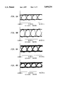
- FIGS. 5A, 5B, 6A, 6B, 7A and 7B show received eye patterns from downstream and upstream transmissions
- FIG. 8 illustrates an embodiment of a passive optical network including a broadcast video overlay
- FIGS. 9A and 9B illustrate optical network units according to embodiments of the present invention.
- FIGS. 10A and 10B illustrate RITE-NETTM optical network units according to various embodiments of the present invention.
- a standard passive optical network model is shown in FIG. 1, consisting of a first fiber star 1, typically a plurality of optical fibers 2 extending from a central office 4, to each one of a plurality of remote nodes 6, i.e., RN 1 , RN 2 , . . . RN N .
- Downstream signals are transmitted from the central office towards the remote nodes for further distribution.
- light is passively split and distributed via a plurality of optical fibers 8 (a second star) to a plurality of optical network units 10, i.e., ONU 1 , ONU 2 , . . . ONU N .
- the optical network units provide service to one or more end users wherein each downstream optical signal is received and electronically distributed to end users.
- the optical network units 10 may transmit upstream signals which are combined at the remote node.
- Each remote node 6 (or passive star) passively combines transmissions from the optical network units 10 onto single optical fiber 2 for distribution to the central office.
- Stern, et al. PASSIVE OPTICAL LOCAL NETWORKS FOR TELEPHONE APPLICATIONS AND BEYOND, ELECTRON LETTERS, vol. 23, pgs. 1255-57 (1987).
- PON passive optical network architectures
- TPON telephony over passive optical networks
- WDM PONs wavelength division multiplexing passive optical networks
- TDM time-division multiplexing
- TDM typically includes a frame of information subdivided into time slots assigned to individual optical network units.
- Wavelength division multiplexing passive optical networks utilize an architecture within which each optical network unit or subscriber is assigned a unique wavelength by the central office.
- Signals destined for each remote node are created by modulating light at N distinct wavelengths (one for each optical network unit) at the central office.
- the modulated light signals are multiplexed onto a fiber directed to the remote node.
- the downstream signals are split and distributed to the optical network unit as a function of wavelength by means of a wavelength division demultiplexer (WDM) at the remote node.
- WDM wavelength division demultiplexer
- the light is transmitted typically by laser at assigned wavelengths consistent with the above WDM.
- RITE-NetTM is one type of wavelength division multiplexing passive optical network that uses a wavelength division multiplexing router (WDM/R) at the remote node, which distinguishes it from a conventional wavelength division multiplexing passive optical network.
- Wavelength division multiplexing router couplers are described in a paper by Dragone, An NxN Optical Multiplexer Using a Planer Arrangement of Two Star Couplers, IEEE Phot. Technol. Lett.
- a multiwavelength laser at the central office sends multiplexer optical signals encoded with data at specific wavelengths to the remote node.
- the downstream signals are routed by the wavelength division multiplexing router according to wavelength to the optical network units.
- the separation between frequencies of the WDM/R sets the system's channel spacing.
- the central office transmitter is designed such that its mode spacing closely matches that of the WDM/R.
- An electronic sequencer and a control circuit insure that data signals modulate the transmitter at the appropriate wavelengths.
- At the optical network unit a portion of the received light is overmodulated with subscriber data and looped back through the remote node to the central office. That is, a modulator at the optical network unit imprints upstream information on a gated CW portion of the downstream signal which is then directed back to the remote node.
- Such a network is referred to as a RITE-NetTM network, as described in commonly-owned U.S.
- LAR-NetTM another wavelength division multiplexing passive optical network, the need for the RITE-NetTM modulator at the ONU is avoided.
- Multi-wavelength signals are sent from the central office over single fibers to a remote node for routing by wavelength to different optical network units.
- a coupler at the optical network unit combines/separates upstream and downstream traffic, directing the downstream traffic to a receiver.
- a broadband incoherent signal source such as an LED, is provided for transmitting upstream communications, replacing the RITE-NetTM modulators.
- the upstream signal is spectrally sliced at the remote node (i.e., the wavelength division multiplexing router) into appropriate wavelength bands to prevent spectral overlap of upstream signals.
- LAR-NetTM network is described in commonly-owned U.S. patent appln. Ser. No. 08/261,5844, filed Jun. 17, 1994, and incorporated herein by reference.
- Passive optical network 12 includes a central office 13 connected by a single fiber 20 to a remote node 22.
- Remote node 22 includes a wavelength router, preferentially, one such as the wavelength division multiplexing router (WDM/R) discussed above, which wavelength slices the downstream signal transmitted from central office 13. The sliced portions of the downstream signal are distributed along single fibers 24, to each of a number of optical network units 26.
- the central office 13 and each of the optical network units 26 contain coarse wavelength division multiplexing optical couplers 18, optical receivers 16 and LEDs 14, 28, respectively, to effect communication channels.
- the coarse WDM couplers 18 located at the central office multiplex/demultiplex the downstream/upstream signals directed to/from the remote node via fiber 20. Distinct downstream and upstream wavelength bands are chosen to avoid reflection, crosstalk, etc., e.g., 1.3 ⁇ m and 1.5 ⁇ m, respectively.
- the WDM couplers 18 located at the optical network units multiplex/demultiplex the upstream/downstream information transmitted along fiber 24 from/to remote node 22.
- the expressions ⁇ dj and ⁇ uk describe slices of the downstream and upstream wavelength bands, respectively.
- the wavelength division multiplexing router (WDM/R) contained therein insures that each downstream port j receives slices of the transmitted signal particular to the optical network unit to which it is directed.
- the periodicity of the wavelength division multiplexing router (WDM/R) insures that each port j receives a signal containing approximately the same optical power, assuming the wavelength spread of LED 14 is large relative to the router's (WDM/R's) free spectral range (FSR). That is, if there are N optical ports, ⁇ dj+mN is the wavelength band that will appear at port j for an integral m which serves as an index for the FSRs.
- each port j receives approximately the same power P.sub. j.
- the entire optical signal generated within LED 28 is frequency selectively directed via each coarse WDM coupler 18 to the remote node 22 via fiber 24.
- remote node 22 Due to the properties of the WDM/R, remote node 22 combines a sliced version of the LED spectrum generated within each optical network unit onto a single optical fiber and directs it to the central office.
- the sliced spectra are automatically interleaved such that the optical frequencies from distinct optical network units do not overlap, thereby preventing, for example, unwanted beat noise.
- Collisions of the signals broadcast from a plurality of optical network units are avoided at the central office by scheduling, by sub-carrier multiplexing (SCM), or by wavelength division (de)multiplexing (WDM).
- SCM sub-carrier multiplexing
- WDM wavelength division (de)multiplexing
- Scheduling is a form of time division multiplexing where, for example, different signals at the same frequency which are transmitted from optical network units are delegated to predefined, calibrated time slots in accordance with a system clock.
- SCM is an arrangement where optical signals transmitted from each optical network unit or central office 13 are coded into unique RF subcarriers that modulate the LED 28 generated broadband light.
- WDM or WDM/R the signals are naturally segregated by wavelength and are therefore amenable to demultiplexing using a wavelength division multiplexer.
- the light received from the remote node is either segregated in time, as in the case of scheduling, or segregated by RF frequency, in the case of SCM, or by wavelength band in the case of WDM, and processed accordingly.
- Passive optical network 30 includes a central office 13' connected to at least one remote node 22' via at least two optical fibers 21 and 23.
- Fiber 21 forms a dedicated downstream path between remote node 22' and LED 14, and fiber 23 forms a dedicated upstream path between remote node 22' and receiver 16.
- a pair of fibers 25, 24, form dedicated downstream and upstream paths to receiver 16 and LED 28, respectively, thereby connecting the remote node to each of the plurality of optical network units 26'.
- the coarse WDM couplers 18 that were described above are generally not required within passive optical network 30 due to the presence of the dedicated upstream and downstream paths 25, 23, and 21, 24, respectively. While the two for one optical fiber requirement for this embodiment reduces the number of users which can be supported by each WDM/R-based remote node 22', implementation of such a network provides a vehicle for the implementation of future technologies directed towards formation of an efficient, high-performance network.
- a prototype of passive optical network 30 of FIG. 3 was built and tested at a baseband transmission of 40-Mb/s at various launched power levels.
- a 4 ⁇ 4 wavelength division multiplexing router (WDM/R) was used at the remote node 22' in the prototype, but connected to only one optical network unit 26' for simplicity in testing.
- Receiver 16 at optical network unit 26' was implemented with a commercially available AC-coupled PIN FET.
- FIGS. 4A and 4B are display photos highlighting the optical spectra captured from LED 28 within optical network unit 26' at a wavelength band of 1.5 ⁇ m, and LED 14 within central office 13' at a wavelength band of 1.3 ⁇ m, respectively, during prototype testing.
- the signals generated within the LEDs are shown in each figure both before and after spectral slicing.
- the LEDs were directly modulated at 100% modulation depth with a non-return-to-zero (NRZ) pseudo-random data stream.
- launched powers for each LED were varied from the LED's maximum rated value P L ,max, down to a value resulting in a detected minimum power required for 1X10 -9 BER P R ,min.
- Electrical crosstalk generated by reflected light impinging on receivers was found to be neglible relative to receiver thermal noise during testing. It can be assumed, therefore, with such an arrangement, that the electrical crosstalk between dedicated upstream and downstream fibers leads to no appreciable performance degradation.
- FIGS. 5A and 5B each show received eye patterns for downstream and upstream transmission through the prototype during testing, respectively.
- Eye patterns are bit-train waveforms seen on a display, the time base of which is typically set to trigger at the bit rate of the transmitted (or broadcast) signal.
- the shape of the eye pattern gives the viewer an indication of both random (noise) and deterministic variations in the received signal which can give rise to errors.
- the wide open eyes in these figures are indicative of low error rate operation.
- the patterns correspond to maximum rated launched power levels of LEDs 14 and 28, respectively.
- the launched downstream power, P L ,max, of LED 14 at Co 13' was measured at -13.3 dBm
- the launched upstream power, P L ,max, of LED 28 at optical network unit 26' was measured at -17.5 dBm.
- the corresponding received powers were found to be -32.3 dBm and -34.5 dBm, respectively, at the downstream and upstream receivers, respectively.
- FIGS. 6A and 6B show received eye patterns for downstream and upstream transmissions, respectively, after the launched LED power levels discussed in relation to FIGS. 5A and 5B were decreased by 10 dB within the prototype.
- the reduction of launched power by 10 dB was found to lower the received power levels to levels commensurate with power losses which would occur during actual field condition transmission.
- FIGS. 6A and 6B are patterns derived from the wavelength division multiplexing router (WDM/R) at remote node 22' when optimized for 1.5 ⁇ m operation.
- the resulting downstream loss through the network was found to be 19 dB, exceeding the total upstream loss of 17 dB by 2 dB.
- Six (6) of the 17 dB are due to the 1 ⁇ 4 split.
- 1 dB results from the connector and 10 db from the wavelength division multiplexing router, i.e., 3 dB from chip loss, 2 dB from pigtails, 1 dB from polarization and 4 dB as a result of the filter function.
- FIGS. 7A and 7B show the combined effects of loss and dispersion, due to transmission through 8 km of the conventional signal mode fiber in the upstream and downstream directions, respectively, within the prototype.
- the launched powers were equal to -17.5 dBm and dBm -13.3 dBm, respectively. As the tests results indicate, the eyes remained open, with only slight evidence of distortion due to chromatic distortion, as seen in a comparison of the figures.
- passive optical network 80 includes central office 81 connected to at least one remote node 82 via at least two optical fibers 83 and 84.
- Fiber 83 forms a dedicated downstream path between central office 81 and remote node 82 and fiber 84 forms a dedicated upstream path between remote node 82 and central office 81.
- each pair of fibers 86 and 87 form dedicated downstream and upstream paths, respectively, to a corresponding ONU 91, thereby connecting remote node 82 to a plurality of ONUs 91.
- Central office 81 includes optical transmitter 88, 1.5 ⁇ m LED 89, optical receiver 90 and wavelength division multiplexing optical coupler (WDM) 85.
- LED 89 is used, as in the previously described embodiments, for transmitting downstream baseband data for point-to-point communication to each of ONUs 91.
- receiver 90 receives upstream information from remote node 82 via fiber 84.
- Optical transmitter 88 can consist of a broadband optical transmitter such as an LED, for distributing a broadcast signal to ONUs 91.
- a digital satellite signal can be received via a commercially available direct satellite receiver (not shown) provided at central office 81.
- the received signal after block conversion into a predefined RF band, can be used to directly modulate broadband optical transmitter 88.
- the broadband output of optical transmitter 88 is then combined or overlayed with the downstream 1.5 ⁇ m baseband data signal from LED 89, by coupler 85.
- the broadcast signal can be coupled onto downstream fiber 83 utilizing several different methods.
- the broadcast signal can be optically coupled in the same optical band as the baseband data signal from LED 89 using a passive combiner.
- the broadcast signal can be optically coupled with a different optical band than the baseband data signal from LED 89 using a passive combiner or a WDM.
- the signals can be separated utilizing a TDM protocol or a SCM protocol.
- a WDM protocol, a TDM protocol or a SCM protocol may be suitably used to separate the signals.
- the point-to-point information from LED 89 is routed to the appropriate ONU by remote node 82.
- the broadcast signal is spectrally sliced at remote node 82, with approximately equal powers being directed to each ONU 91.
- the downstream broadband signal from optical transmitter 88 and the baseband signal from 1.5 ⁇ m LED 89 are separated using an RF separation technique or an optical separation technique.
- receiver 92 receives the downstream optical signals and electronically demultiplexes the signals utilizing a known technique, such as a TDM or SCM demultiplexing technique.
- the point-to-point information can then be processed for receipt by a telephone or other terminal device, for example.
- the broadcast information can be processed for receipt by a television, for example.
- Transmitter 93 can consist of an optical source such as an LED, which can be modulated for transmitting upstream information, as described in previous embodiments.
- the received downstream optical signals are optically demultiplexes.
- optical decoupler 95 demultiplexes the optical signals such that the broadcast signal is directed to an appropriate receiver 94 where it can be processed as necessary for viewing on a television, for example.
- the baseband signal is directed to an appropriate receiver 96 where it can also be processed as necessary for receipt by a telephone or other terminal device, for example.
- FIG. 10A Another embodiment of the present invention for performing electrical separation of the downstream signals utilizing a RITE-NetTM type architecture, is depicted in FIG. 10A.
- the downstream optical signals e.g., both the broadcast information and point-to-point information
- the downstream optical signals are received by coupler 102 via fiber 86.
- a portion of the received signal is modulated with upstream information by modulator 103 and looped back to RN 82 via fiber 87.
- a portion of the signal demultiplexed by coupler 102 is also provided to receiver 104 which can perform electrical separation of the received signals using a known technique (such as utilizing TDM or SCM techniques).
- FIG. 10B Still another embodiment of the present invention for performing optical separation of the downstream signals utilizing a RITE-NetTM type architecture is depicted in FIG. 10B.
- the downstream optical signals are received from remote node 82 and split by coupler 105, with the broadcast portion of the signal being routed to receiver 106.
- the point-to-point information signal is routed to coupler 107, where a portion of the signal is directed to modulator 108 where it is modulated with upstream information for transmission to RN 82 via fiber 87.
- a portion of the point-to-point information signal demultiplexed by coupler 107 is also provided to receiver 109.
- a broadband signal such as a broadcast TV signal, for example, can be provided to each ONU 91.
- the broadcast signal could also consist of a radio signal or any other desired type of broadcast signal.
- optical transmitter 88 could consist of a multi-frequency laser for providing additional point-to-point information to ONUs 91.
- the present invention has been described with respect to the use of dedicated downstream and upstream fibers, it should be apparent that the present invention may also be implemented utilizing a single fiber for both the downstream and upstream signals.
- a passive optical network architecture defined according to this invention provides a number of distinct advantages over the prior art, most importantly, system implementation cost reductions. Because dedicated LEDs may be used for transmitting in both directions, the need for sources such as lasers operating at a discrete set of frequencies is avoided at both the central office and optical network units, and the need for modulators is avoided at the optical network units. By providing a broadband source also, a broadcast signal such as a TV or radio signal can be provided to all of the optical network units, thus providing another potential revenue producing service in the system.
- the broadcast overlay is also compatible with any upgrades to high performance WDM passive optical networks such as RITE-NetTM, for example.
Abstract
Description
Claims (20)
Priority Applications (1)
| Application Number | Priority Date | Filing Date | Title |
|---|---|---|---|
| US08/527,967 US5694234A (en) | 1994-10-20 | 1995-08-14 | Wavelength division multiplexing passive optical network including broadcast overlay |
Applications Claiming Priority (2)
| Application Number | Priority Date | Filing Date | Title |
|---|---|---|---|
| US32657694A | 1994-10-20 | 1994-10-20 | |
| US08/527,967 US5694234A (en) | 1994-10-20 | 1995-08-14 | Wavelength division multiplexing passive optical network including broadcast overlay |
Related Parent Applications (1)
| Application Number | Title | Priority Date | Filing Date |
|---|---|---|---|
| US32657694A Continuation-In-Part | 1994-10-20 | 1994-10-20 |
Publications (1)
| Publication Number | Publication Date |
|---|---|
| US5694234A true US5694234A (en) | 1997-12-02 |
Family
ID=23272811
Family Applications (3)
| Application Number | Title | Priority Date | Filing Date |
|---|---|---|---|
| US08/366,849 Expired - Lifetime US5680234A (en) | 1994-10-20 | 1994-12-30 | Passive optical network with bi-directional optical spectral slicing and loop-back |
| US08/527,967 Expired - Lifetime US5694234A (en) | 1994-10-20 | 1995-08-14 | Wavelength division multiplexing passive optical network including broadcast overlay |
| US08/595,816 Expired - Lifetime US5574584A (en) | 1994-10-20 | 1996-03-22 | Wavelength division multiplexing passive optical network with bi-directional optical spectral slicing |
Family Applications Before (1)
| Application Number | Title | Priority Date | Filing Date |
|---|---|---|---|
| US08/366,849 Expired - Lifetime US5680234A (en) | 1994-10-20 | 1994-12-30 | Passive optical network with bi-directional optical spectral slicing and loop-back |
Family Applications After (1)
| Application Number | Title | Priority Date | Filing Date |
|---|---|---|---|
| US08/595,816 Expired - Lifetime US5574584A (en) | 1994-10-20 | 1996-03-22 | Wavelength division multiplexing passive optical network with bi-directional optical spectral slicing |
Country Status (4)
| Country | Link |
|---|---|
| US (3) | US5680234A (en) |
| EP (1) | EP0708540A1 (en) |
| JP (1) | JPH08237223A (en) |
| CA (1) | CA2160823C (en) |
Cited By (90)
| Publication number | Priority date | Publication date | Assignee | Title |
|---|---|---|---|---|
| US5864413A (en) * | 1996-02-23 | 1999-01-26 | Lucent Technologies, Inc. | Passive optical network for dense WDM downstream data transmission and upstream data transmission |
| US5880865A (en) * | 1996-12-03 | 1999-03-09 | Lucent Technologies Inc. | Wavelength-division-multiplexed network having broadcast capability |
| US6014237A (en) * | 1998-06-01 | 2000-01-11 | Sarnoff Corporation | Multiwavelength mode-locked dense wavelength division multiplexed optical communication systems |
| US6147784A (en) * | 1996-08-27 | 2000-11-14 | At&T Corp. | Simultaneous wavelength-division multiplexing and broadcast transmission system |
| WO2000074278A1 (en) * | 1999-05-28 | 2000-12-07 | Advanced Fibre Communications | Wdm passive optical network with broadcast overlay |
| US6192172B1 (en) | 1999-08-09 | 2001-02-20 | Lucent Technologies Inc. | Optical wavelength-space cross-connect switch architecture |
| US6192058B1 (en) | 1998-09-18 | 2001-02-20 | Sarnoff Corporation | Multiwavelength actively mode-locked external cavity semiconductor laser |
| US20010004290A1 (en) * | 1999-12-21 | 2001-06-21 | Lee Chang Hee | Low-cost WDM source with an incoherent light injected fabry-perot laser diode |
| US6388782B1 (en) | 1998-06-01 | 2002-05-14 | Sarnoff Corporation | Multi-wavelength dense wavelength division multiplexed optical switching systems |
| US6407846B1 (en) | 2001-03-16 | 2002-06-18 | All Optical Networks, Inc. | Photonic wavelength shifting method |
| US6552832B1 (en) * | 1996-10-07 | 2003-04-22 | Telesector Resources Group, Inc. | Telecommunications system including transmultiplexer installed between digital switch and optical signal transmission fiber |
| EP1306990A2 (en) * | 2001-10-25 | 2003-05-02 | Nippon Telegraph and Telephone Corporation | Optical communication system with control of output level |
| US6577414B1 (en) | 1998-02-20 | 2003-06-10 | Lucent Technologies Inc. | Subcarrier modulation fiber-to-the-home/curb (FTTH/C) access system providing broadband communications |
| US6577422B1 (en) | 1998-02-18 | 2003-06-10 | At&T Corp. | Long reach delivery of broadcast services using broadband optical sources and pre-compensation dispersion |
| WO2003055111A1 (en) * | 2001-12-21 | 2003-07-03 | Nokia Corporation | Optical transmission network |
| US20030128718A1 (en) * | 2001-10-10 | 2003-07-10 | Matthews Paul J. | Method for switching and routing large bandwidth continuous data streams from a centralized location |
| US20030206740A1 (en) * | 2002-05-03 | 2003-11-06 | Lee Chang Hee | Wavelength-tunable light source and wavelength-division multiplexed transmission system using the source |
| US20030235412A1 (en) * | 2002-06-20 | 2003-12-25 | Alcatel | Optical ring network with decoupled read and write fibers |
| US6678442B2 (en) * | 2002-04-24 | 2004-01-13 | Pangrac And Associates Development, Inc. | Fiber optic connector for a segmented FTTH optical network |
| US20040047630A1 (en) * | 2001-01-18 | 2004-03-11 | Robert Furst | Optical broadband transmission device and distribution method |
| EP1418691A2 (en) * | 2002-11-07 | 2004-05-12 | Samsung Electronics Co., Ltd. | Passive optical network using loop back of multi-wavelength light generated at central office |
| EP1434375A2 (en) * | 2002-12-26 | 2004-06-30 | Nippon Telegraph and Telephone Corporation | Optical network unit, wavelength splitter, and optical wavelength-division multiplexing access system |
| US20040208545A1 (en) * | 2001-12-13 | 2004-10-21 | Ali Langari | Optical switch with enhanced flexibility |
| US20040234195A1 (en) * | 2003-05-20 | 2004-11-25 | Olli-Pekka Pohjola | Optical data transmission system |
| US20050025484A1 (en) * | 2003-07-28 | 2005-02-03 | Dae-Kwang Jung | Wavelength-division-multiplexed passive optical network using multi-wavelength lasing source and reflective optical amplification means |
| US6868233B2 (en) * | 2000-12-14 | 2005-03-15 | Alcatel Usa Sourcing, L.P. | Wavelength agile optical transponder for bi-directional, single fiber WDM system testing |
| EP1519616A2 (en) * | 2003-09-26 | 2005-03-30 | Samsung Electronics Co., Ltd. | Ethernet passive optical network integrating image broadcast and data communication based on time division multiplexing |
| KR100489922B1 (en) * | 2002-10-01 | 2005-05-17 | 최준국 | Dense wavelength division multiplexing-passive optical network using self-injection locking of fabry-perot laser diode |
| US20050135449A1 (en) * | 2003-12-19 | 2005-06-23 | Sorin Wayne V. | Integration of laser sources and detectors for a passive optical network |
| US20050141077A1 (en) * | 2003-12-30 | 2005-06-30 | Sang-Ho Kim | Multi-wavelength light source and wavelength division multiplexing system using the same |
| KR100514383B1 (en) * | 2002-08-06 | 2005-09-13 | 최준국 | Wavelength division multiplexing-passive optical network using same wavelength as upstream and downstream chanel |
| US20060045542A1 (en) * | 2002-09-19 | 2006-03-02 | Chang-Hee Lee | Apparatuses and methods for automatic wavelength locking of an optical transmitter to the wavelength of an injected incoherent light signal |
| US20060083515A1 (en) * | 2004-10-20 | 2006-04-20 | Kwangju Institute Of Science And Technology | WDM-PON having optical source of self-injection locked fabry-perot laser diode |
| KR100575953B1 (en) * | 2003-10-27 | 2006-05-02 | 삼성전자주식회사 | Optical signal transmitter with reflective gain clamped semiconductor optical amplifier and optical communicating system using thereof |
| US20060153565A1 (en) * | 2005-01-12 | 2006-07-13 | Samsung Electronics Co.; Ltd | Hybrid passive optical network |
| US20060153566A1 (en) * | 2005-01-13 | 2006-07-13 | Sorin Wayne V | Methods and apparatuses to provide a wavelength-division-multiplexing passive optical network with asymmetric data rates |
| US20060153567A1 (en) * | 2005-01-12 | 2006-07-13 | Samsung Electronics Co.; Ltd | Wavelength-division multiplexing-passive optical network |
| US7079768B2 (en) | 2000-10-03 | 2006-07-18 | Lucent Technologies Inc. | Dynamic passive optical network (PON) using a distributed optical cross connect and dense wavelength division multiplexing |
| KR100606102B1 (en) * | 2002-08-03 | 2006-07-28 | 삼성전자주식회사 | Broadcast/communication unified passive optical network system |
| KR100640485B1 (en) | 2005-07-26 | 2006-10-30 | 삼성전자주식회사 | Bidirectional optical passive network |
| US20060245687A1 (en) * | 2005-05-02 | 2006-11-02 | Pangrac & Associates Development, Inc. | Low-loss shared ftth distribution network |
| US20060245688A1 (en) * | 2005-05-02 | 2006-11-02 | Pangrac & Associates Development, Inc. | Optical conversion device for shared ftth distribution network |
| US7181142B1 (en) | 2002-04-09 | 2007-02-20 | Time Warner Cable Inc. | Broadband optical network apparatus and method |
| KR100703470B1 (en) | 2005-04-18 | 2007-04-03 | 삼성전자주식회사 | Wavelength division multiplexed light source and passive optical network using the same |
| KR100711201B1 (en) | 2005-08-09 | 2007-04-24 | 한국과학기술원 | The long-reach wavelength division multiplexing passive optical networks by using the position adjustment of broadband light source |
| US20070092249A1 (en) * | 2005-10-20 | 2007-04-26 | Yoichi Akasaka | System and Method for Traffic Distribution in an Optical Network |
| US20070092250A1 (en) * | 2005-10-20 | 2007-04-26 | Martin Bouda | Distribution components for a wavelength-sharing network |
| US20070092253A1 (en) * | 2005-10-20 | 2007-04-26 | Martin Bouda | Distribution node for a wavelength-sharing network |
| US20070092255A1 (en) * | 2005-10-20 | 2007-04-26 | Martin Bouda | System and Method for Distributing Traffic in an Optical Network |
| US20070092251A1 (en) * | 2005-10-20 | 2007-04-26 | Martin Bouda | Hybrid passive optical network using shared wavelengths |
| US20070092254A1 (en) * | 2005-10-20 | 2007-04-26 | Martin Bouda | System and Method for Transmitting Upstream Traffic in an Optical Network |
| US20070092252A1 (en) * | 2005-10-20 | 2007-04-26 | Martin Bouda | Upgradeable passive optical network |
| US20070140693A1 (en) * | 2005-12-13 | 2007-06-21 | Wen Li | Fiber-to-the-premise optical communication system |
| US20070165688A1 (en) * | 2003-05-29 | 2007-07-19 | Chang-Hee Lee | Light source cable of lasing that is wavelength locked by an injected light signal |
| US20070166037A1 (en) * | 2006-01-06 | 2007-07-19 | Paparao Palacharla | System and Method for Managing Network Components in a Hybrid Passive Optical Network |
| US20070183779A1 (en) * | 2006-02-03 | 2007-08-09 | Martin Bouda | System and Method for Extending Reach in a Passive Optical Network |
| US20070249661A1 (en) * | 2004-09-21 | 2007-10-25 | Synta Pharmaceuticals Corp. | Compounds for inflammation and immune-related uses |
| US20070264021A1 (en) * | 2006-04-28 | 2007-11-15 | Wen Li | High-speed fiber-to-the-premise optical communication system |
| US20070280690A1 (en) * | 2006-06-02 | 2007-12-06 | Fujitsu Limited | System and Method for Managing Power in an Optical Network |
| US20070280691A1 (en) * | 2006-06-02 | 2007-12-06 | Martin Bouda | System and Method for Transmitting Traffic in a Plurality of Passive Optical Networks |
| US20070280695A1 (en) * | 2006-06-02 | 2007-12-06 | Wen Li | Adaptive optical transceiver for fiber access communications |
| US20080089699A1 (en) * | 2006-10-17 | 2008-04-17 | Wen Li | Methods for automatic tuning optical communication system |
| US20080131129A1 (en) * | 2006-01-06 | 2008-06-05 | Fujitsu Limited | Distribution node for an optical network |
| US20080138063A1 (en) * | 2006-12-11 | 2008-06-12 | Youichi Akasaka | System and Method for Protecting an Optical Network |
| US20080181613A1 (en) * | 2007-01-26 | 2008-07-31 | Martin Bouda | System and Method for Managing Different Transmission Architectures in a Passive Optical Network |
| US20080215221A1 (en) * | 2005-06-22 | 2008-09-04 | Luk Lamellen Und Kupplungsbau Beteiligungs Kg | Clutch reference position |
| US20080273877A1 (en) * | 2007-05-02 | 2008-11-06 | Paparao Palacharla | System and Method for Managing Communication in a Hybrid Passive Optical Network |
| US20080279567A1 (en) * | 2007-05-09 | 2008-11-13 | Wen Huang | Asymmetric ethernet optical network system |
| US20090092394A1 (en) * | 2007-10-08 | 2009-04-09 | Nec Laboratories America, Inc. | Orthogonal Frequency Division Multiple Access Based Virtual Passive Optical Network (VPON) |
| US20090116845A1 (en) * | 2007-11-02 | 2009-05-07 | Wen Li | Tetintelligent optical transceiver capable of optical-layer management |
| US20090185807A1 (en) * | 2005-09-20 | 2009-07-23 | Chang-Hee Lee | Wavelength Division Multiplexing Passive Optical Network for Providing Both of Broadcasting Service and Communication Service and Central Office Used Thereof |
| US20090202245A1 (en) * | 2008-02-13 | 2009-08-13 | Fujitsu Limited | System and Method for Increasing Upstream Capacity in an Optical Network |
| US20090214221A1 (en) * | 2008-02-21 | 2009-08-27 | Wen Li | Intelligent optical systems and methods for optical-layer management |
| US20090304384A1 (en) * | 2008-06-05 | 2009-12-10 | Wen Li | Intelligent pluggable transceiver stick capable of diagnostic monitoring and optical network management |
| US20090324237A1 (en) * | 2008-06-26 | 2009-12-31 | Fulin Pan | Pluggable optical network unit capable of status indication |
| US20100021164A1 (en) * | 2008-07-25 | 2010-01-28 | Nortel Networks Limited | Wdm pon rf/video broadcast overlay |
| EP2157722A1 (en) * | 2008-08-21 | 2010-02-24 | LG - Nortel Co., Ltd. | WDM PON RF overlay architecture based on quantum dot multi-wavelength laser source |
| US20100046950A1 (en) * | 2008-08-21 | 2010-02-25 | Nortel Networks Limited | Seeding wdm pon system based on quantum dot multi-wavelength laser source |
| US20100215359A1 (en) * | 2009-02-22 | 2010-08-26 | Wen Li | Smart optical transceiver having integrated optical dying gasp function |
| CN101346006B (en) * | 2008-08-19 | 2011-01-19 | 武汉长光科技有限公司 | Radio frequency passive optical network with broadband wireless and optical transmission amalgamation access |
| US7912372B2 (en) | 2002-12-24 | 2011-03-22 | Korea Advanced Institute Of Science And Technology | Optical access network using wavelength-locked WDM optical source injected by incoherent light |
| CN101286803B (en) * | 2008-05-30 | 2011-07-06 | 北京北方烽火科技有限公司 | Optimizing method for dual and locked mode optical fiber wireless wave division multiplexing system |
| EP1468515B1 (en) * | 2002-01-21 | 2013-08-14 | NOVERA OPTICS, INC.(a corporation of Delaware) | Methods and apparatuses to provide a wdm passive optical network with wavelength-locked wdm light sources |
| US8565599B2 (en) | 2006-12-11 | 2013-10-22 | Fujitsu Limited | System and method for transmitting optical markers in a passive optical network system |
| US8571410B2 (en) | 2006-10-11 | 2013-10-29 | Novera Optics, Inc. | Mutual wavelength locking in WDM-PONS |
| CN103563274A (en) * | 2013-04-28 | 2014-02-05 | 华为技术有限公司 | Optical device, wireless signal transmitting device and system |
| US8861963B2 (en) | 2003-05-30 | 2014-10-14 | Novera Optics, Inc. | Shared high-intensity broadband light source for a wavelength-division multiple access passive optical network |
| US9130671B2 (en) | 2005-09-07 | 2015-09-08 | Korea Advanced Institute Of Science And Technology | Apparatus for monitoring failure positions in wavelength division multiplexing-passive optical networks and wavelength division multiplexing-passive optical network systems having the apparatus |
| US9674591B2 (en) | 2015-06-08 | 2017-06-06 | Time Warner Cable Enterprises Llc | Methods and apparatus for asymmetric distribution of mixed content via a network |
| US9948399B2 (en) | 2015-01-09 | 2018-04-17 | Time Warner Cable Enterprises Llc | Methods and apparatus for removing beat interference from splitters/combiners |
Families Citing this family (54)
| Publication number | Priority date | Publication date | Assignee | Title |
|---|---|---|---|---|
| US6108113A (en) * | 1995-12-29 | 2000-08-22 | Mci Communications Corporation | Method and system for transporting ancillary network data |
| US5907420A (en) * | 1996-09-13 | 1999-05-25 | Lucent Technologies, Inc. | System and method for mitigating cross-saturation in optically amplified networks |
| US5742414A (en) * | 1996-09-24 | 1998-04-21 | At&T Corp. | Multiplicity of services via a wavelength division router |
| NL1004667C2 (en) * | 1996-12-02 | 1998-06-03 | Nederland Ptt | Optical systems with one or more stabilized laser signal sources. |
| FI103619B1 (en) | 1997-05-26 | 1999-07-30 | Nokia Telecommunications Oy | Optical multiplexing and demultiplexing |
| US6072612A (en) * | 1997-08-08 | 2000-06-06 | Lucent Technologies, Inc. | WDM transmitter for optical networks using a loop-back spectrally sliced light emitting device |
| US6631018B1 (en) | 1997-08-27 | 2003-10-07 | Nortel Networks Limited | WDM optical network with passive pass-through at each node |
| US6041152A (en) * | 1997-09-02 | 2000-03-21 | Amphenol Corporation | Multi-channel fiber optic communications system and multiplexer/demultiplexer arrangement therefor |
| US6151144A (en) * | 1998-01-20 | 2000-11-21 | Lucent Technologies, Inc. | Wavelength division multiplexing for unbundling downstream fiber-to-the-home |
| US6144472A (en) * | 1998-01-20 | 2000-11-07 | Lucent Technologies Inc. | Upgrading a power-splitting passive optical network using optical filtering |
| US6137608A (en) * | 1998-01-30 | 2000-10-24 | Lucent Technologies Inc. | Optical network switching system |
| JPH11275028A (en) * | 1998-03-20 | 1999-10-08 | Fujitsu Ltd | Optical communication system |
| US5943457A (en) * | 1998-03-24 | 1999-08-24 | Telecommunications Research Laboratories | Generalized resonant coupler filters |
| US6650840B2 (en) * | 1998-03-27 | 2003-11-18 | Lucent Technologies Inc. | Method for identifying faults in a branched optical network |
| US6381047B1 (en) | 1998-05-06 | 2002-04-30 | At&T Corp. | Passive optical network using a fabry-perot laser as a multiwavelength source |
| IT1301848B1 (en) * | 1998-07-23 | 2000-07-07 | Sirti Spa | PASSIVE SYSTEM FOR SURVEILLANCE OF OPTICAL DISTRIBUTION NETWORKS WITH TREE STRUCTURE |
| US6366713B1 (en) * | 1998-09-04 | 2002-04-02 | Tellabs Operations, Inc. | Strictly non-blocking optical switch core having optimized switching architecture based on reciprocity conditions |
| DE19909565A1 (en) * | 1999-03-04 | 2000-10-05 | Siemens Ag | Process for monitoring the operation of optical fibers |
| US6583867B1 (en) * | 1999-08-13 | 2003-06-24 | Fitel Usa Corp. | System and method for monitoring optical fiber integrity between the telecommunications provider and a customer's premises |
| US6498667B1 (en) * | 1999-09-10 | 2002-12-24 | Quantum Bridge Communications, Inc. | Method and system for packet transmission over passive optical network |
| KR100337131B1 (en) * | 1999-10-14 | 2002-05-18 | 윤덕용 | Bi-directional, subcarrier-multiplexed self-healing ring optical network |
| JP2001223642A (en) * | 2000-02-09 | 2001-08-17 | Sumitomo Electric Ind Ltd | Optical communication unit |
| JP2001339348A (en) * | 2000-05-26 | 2001-12-07 | Nec Corp | Photocoupler monitor system |
| US6850662B1 (en) | 2000-07-31 | 2005-02-01 | Tellabs Operations, Inc. | Optical switch for reciprocal traffic |
| US6363182B2 (en) | 2000-07-31 | 2002-03-26 | James D. Mills | Optical switch for reciprocal traffic |
| US6771908B2 (en) * | 2001-02-12 | 2004-08-03 | Lucent Technologies Inc. | Fast protection switching by snooping on downstream signals in an optical network |
| US6778781B2 (en) | 2001-02-12 | 2004-08-17 | Lucent Technologies Inc. | Health check algorithm for protection circuit in optical network |
| US6868232B2 (en) * | 2001-02-12 | 2005-03-15 | Lucent Technologies Inc. | Fast protection switching by snooping on upstream signals in an optical network |
| US20020131125A1 (en) * | 2001-03-16 | 2002-09-19 | Myers Michael H. | Replicated-spectrum photonic transceiving |
| US20020131106A1 (en) | 2001-03-16 | 2002-09-19 | Peter Snawerdt | Secure wave-division multiplexing telecommunications system and method |
| US20030007724A1 (en) * | 2001-07-05 | 2003-01-09 | Broadcom Corporation | System, method, and computer program product for optimizing video service in ethernet-based fiber optic TDMA networks |
| WO2003007024A2 (en) * | 2001-07-09 | 2003-01-23 | Oyster Optics, Inc. | Fiber optic telecommunications card with security detection |
| KR100735692B1 (en) * | 2001-07-12 | 2007-07-06 | 엘지전자 주식회사 | Code modulation method for using adaptive modulation and acknowledge |
| US7155127B2 (en) | 2001-08-15 | 2006-12-26 | Nippon Telegraph And Telephone Corporation | Optical communication system, optical communication unit, and optical transceiving package |
| US7058301B2 (en) | 2002-02-28 | 2006-06-06 | Bosloy Jonathan L | Apparatus and method for planned wavelength addition and removal in a wavelength division multiplexed system |
| US20030216945A1 (en) * | 2002-03-25 | 2003-11-20 | Dvorak Carl D. | Method for analyzing orders and automatically reacting to them with appropriate responses |
| US6873763B2 (en) * | 2002-04-12 | 2005-03-29 | Intel Corporation | Managing channels with different wavelengths in optical networks |
| US8750702B1 (en) * | 2002-06-21 | 2014-06-10 | Rockstar Consortium Us Lp | Passive optical loopback |
| KR100547709B1 (en) * | 2003-07-07 | 2006-01-31 | 삼성전자주식회사 | Self-Healing Wavelength Division Multiplexing Passive Optical Subscriber Network |
| US7062171B2 (en) * | 2003-07-15 | 2006-06-13 | Yusuke Ota | Multi-wavelength, bi-directional optical multiplexer |
| FR2859054B1 (en) * | 2003-08-19 | 2006-12-29 | Cit Alcatel | DYNAMIC CONTROL OF LOSS OF POWER IN AN OPTICAL FIBER BY CONTRAPROPAGATION OF A SUPERVISORY CHANNEL |
| US7680388B2 (en) * | 2004-11-03 | 2010-03-16 | Adc Telecommunications, Inc. | Methods for configuring and testing fiber drop terminals |
| US20060147203A1 (en) * | 2004-12-30 | 2006-07-06 | Thinguldstad Arthur M | Optical network element with remote access capability |
| MX2007012996A (en) | 2005-04-19 | 2007-12-13 | Adc Telecommunications Inc | Loop back plug and method. |
| US7324922B2 (en) * | 2005-10-26 | 2008-01-29 | International Business Machines Corporation | Run-time performance verification system |
| FR2893469B1 (en) * | 2005-11-17 | 2007-12-14 | Alcatel Sa | IMPROVED DATA TRANSMISSION DEVICES FOR COMMUNICATION EQUIPMENT OF A PASSIVE OPTICAL NETWORK |
| WO2011143401A2 (en) | 2010-05-14 | 2011-11-17 | Adc Telecommunications, Inc. | Splice enclosure arrangement for fiber optic cables |
| US8885998B2 (en) | 2010-12-09 | 2014-11-11 | Adc Telecommunications, Inc. | Splice enclosure arrangement for fiber optic cables |
| US20120288273A1 (en) * | 2011-05-12 | 2012-11-15 | Alcatel-Lucent Usa, Inc. | Intelligent splitter monitor |
| US8923672B2 (en) * | 2011-11-10 | 2014-12-30 | Alcatel Lucent | Wavelength router for a passive optical network |
| US10270526B2 (en) * | 2016-11-07 | 2019-04-23 | Electronics And Telecommunications Research Institute | Apparatus and method for monitoring status of terminal |
| CN107317624B (en) * | 2017-06-05 | 2021-12-07 | 深圳市飞鸿光电子有限公司 | Passive optical network ranging method and system |
| CN112242871B (en) * | 2019-07-19 | 2023-03-28 | 上海诺基亚贝尔股份有限公司 | Method, apparatus and computer-readable storage medium for optical communication |
| EP3795980A1 (en) * | 2019-09-19 | 2021-03-24 | Nokia Technologies Oy | Photoacoustic apparatus and methods |
Citations (9)
| Publication number | Priority date | Publication date | Assignee | Title |
|---|---|---|---|---|
| US5058102A (en) * | 1989-01-31 | 1991-10-15 | Alcatal N.V. | Broadband optical communication system, particularly for the subscriber area |
| US5119223A (en) * | 1989-09-28 | 1992-06-02 | Siemens Aktiengesellschaft | Bidirectional light waveguide (LWG) telecommunication system and method for wavelength separation mode (bidirectional wavelength separation mode (WDM) between a central telecommunication location and plurality of decentralized telecommunication locations |
| US5136411A (en) * | 1987-12-11 | 1992-08-04 | General Instrument Corporation | Dynamically responsive CATV system with shared fiber optic link |
| US5202780A (en) * | 1989-04-22 | 1993-04-13 | Alcatel N.V. | Optical communication system for the subscriber area |
| US5221983A (en) * | 1989-01-19 | 1993-06-22 | Bell Communications Research, Inc. | Passive photonic loop architecture employing wavelength multiplexing |
| US5241409A (en) * | 1989-02-08 | 1993-08-31 | British Telecommunications Public Limited Company | Communications network with switching distributed among a central switching node and optical input and output sub-networks |
| US5272556A (en) * | 1989-05-25 | 1993-12-21 | British Telecommunications | Optical networks |
| US5285305A (en) * | 1991-12-12 | 1994-02-08 | At & T Bell Laboratories | Optical communication network with passive monitoring |
| US5479286A (en) * | 1993-08-04 | 1995-12-26 | British Telecommunications Public Limited Company | Optical fibre communications system |
Family Cites Families (10)
| Publication number | Priority date | Publication date | Assignee | Title |
|---|---|---|---|---|
| GB2228846B (en) * | 1989-03-01 | 1993-08-18 | Stc Plc | Fibre optic transmission system |
| US5212579A (en) * | 1991-03-11 | 1993-05-18 | General Instrument Corporation | Method and apparatus for communicating amplitude modulated signals over an optical communication path |
| BE1004813A3 (en) * | 1991-05-08 | 1993-02-02 | Bell Telephone Mfg | OPTICAL TRANSMITTER / RECEIVER. |
| FR2682239B1 (en) * | 1991-10-04 | 1994-11-04 | Cit Alcatel | BIDIRECTIONAL TRANSMISSION SYSTEM, IN PARTICULAR BY OPTICAL FIBER, WITH A SINGLE CARRIER FOR BOTH WAYS OF TRANSMISSION. |
| EP0617876B1 (en) * | 1991-12-19 | 1997-02-12 | Nortel Networks Corporation | Fibre optic telephone loop network |
| US5335104A (en) * | 1992-10-22 | 1994-08-02 | Laser Precision Corp. | Method of detecting breaks in multi-drop feeder systems |
| CA2118616C (en) * | 1993-03-11 | 1999-09-14 | Thomas Edward Darcie | Optical network based on remote interrogation of terminal equipment |
| US5504606A (en) * | 1994-06-01 | 1996-04-02 | At&T Corp. | Low power optical network unit |
| US5550666A (en) * | 1994-06-17 | 1996-08-27 | Lucent Technologies Inc. | Wavelength division multiplexed multi-frequency optical source and broadband incoherent optical source |
| US5502587A (en) * | 1994-06-30 | 1996-03-26 | At&T Corp. | Network comprising a space division photonic switch and a terminal which forms an output signal from an input signal |
-
1994
- 1994-12-30 US US08/366,849 patent/US5680234A/en not_active Expired - Lifetime
-
1995
- 1995-08-14 US US08/527,967 patent/US5694234A/en not_active Expired - Lifetime
- 1995-10-11 EP EP95307186A patent/EP0708540A1/en not_active Withdrawn
- 1995-10-18 CA CA002160823A patent/CA2160823C/en not_active Expired - Fee Related
- 1995-10-20 JP JP7271661A patent/JPH08237223A/en active Pending
-
1996
- 1996-03-22 US US08/595,816 patent/US5574584A/en not_active Expired - Lifetime
Patent Citations (9)
| Publication number | Priority date | Publication date | Assignee | Title |
|---|---|---|---|---|
| US5136411A (en) * | 1987-12-11 | 1992-08-04 | General Instrument Corporation | Dynamically responsive CATV system with shared fiber optic link |
| US5221983A (en) * | 1989-01-19 | 1993-06-22 | Bell Communications Research, Inc. | Passive photonic loop architecture employing wavelength multiplexing |
| US5058102A (en) * | 1989-01-31 | 1991-10-15 | Alcatal N.V. | Broadband optical communication system, particularly for the subscriber area |
| US5241409A (en) * | 1989-02-08 | 1993-08-31 | British Telecommunications Public Limited Company | Communications network with switching distributed among a central switching node and optical input and output sub-networks |
| US5202780A (en) * | 1989-04-22 | 1993-04-13 | Alcatel N.V. | Optical communication system for the subscriber area |
| US5272556A (en) * | 1989-05-25 | 1993-12-21 | British Telecommunications | Optical networks |
| US5119223A (en) * | 1989-09-28 | 1992-06-02 | Siemens Aktiengesellschaft | Bidirectional light waveguide (LWG) telecommunication system and method for wavelength separation mode (bidirectional wavelength separation mode (WDM) between a central telecommunication location and plurality of decentralized telecommunication locations |
| US5285305A (en) * | 1991-12-12 | 1994-02-08 | At & T Bell Laboratories | Optical communication network with passive monitoring |
| US5479286A (en) * | 1993-08-04 | 1995-12-26 | British Telecommunications Public Limited Company | Optical fibre communications system |
Non-Patent Citations (16)
| Title |
|---|
| BT Technical Journal Apr. 1993, "inpact of New Optical Technology on Spectrally-Sliced", pp. 46-55. |
| BT Technical Journal Apr. 1993, inpact of New Optical Technology on Spectrally Sliced , pp. 46 55. * |
| C. Dragone, "An N X N Optical Multiplexer Using a Planar Arrangement of Two Star Couplers", IEEE Photonics Technology Letters, vol. 3, No. 9, pp. 812-185, Sep. 1991. |
| C. Dragone, An N X N Optical Multiplexer Using a Planar Arrangement of Two Star Couplers , IEEE Photonics Technology Letters, vol. 3, No. 9, pp. 812 185, Sep. 1991. * |
| Electronic Letters "Experimental Demonstration of a Passive Optical Subscriber Loop Architecture", vol. 24, No. 6, pp. 344-345. |
| Electronic Letters "Led Spectral Slicing for Single-Mode Local Loop Applications", vol. 24, No. 7 pp. 389-390. |
| Electronic Letters "Passive Optical Local Networks for Telephone Applications and Beyond", vol. 23, No. 24, pp. 1255-1257. |
| Electronic Letters "Use of a Fibre Loop Reflector as Downstream Receiver and Upstream Modulator", vol. 26, No. 6, pp. 827-828. |
| Electronic Letters Experimental Demonstration of a Passive Optical Subscriber Loop Architecture , vol. 24, No. 6, pp. 344 345. * |
| Electronic Letters Led Spectral Slicing for Single Mode Local Loop Applications , vol. 24, No. 7 pp. 389 390. * |
| Electronic Letters Passive Optical Local Networks for Telephone Applications and Beyond , vol. 23, No. 24, pp. 1255 1257. * |
| Electronic Letters Use of a Fibre Loop Reflector as Downstream Receiver and Upstream Modulator , vol. 26, No. 6, pp. 827 828. * |
| Photonics Technology Letters, "Integrated Optics NxN Multiplexer on Silicon", Oct. 1991, vol. 3, No. 10. |
| Photonics Technology Letters, Integrated Optics NxN Multiplexer on Silicon , Oct. 1991, vol. 3, No. 10. * |
| Proc 2 Annu Broadband Expo 14 Fiber Opt Comm Local Area Network Expo Broad Band 90. "Bi-Directional Broadband Local Network Evolution", pp. 314-318. |
| Proc 2 Annu Broadband Expo 14 Fiber Opt Comm Local Area Network Expo Broad Band 90. Bi Directional Broadband Local Network Evolution , pp. 314 318. * |
Cited By (168)
| Publication number | Priority date | Publication date | Assignee | Title |
|---|---|---|---|---|
| US5864413A (en) * | 1996-02-23 | 1999-01-26 | Lucent Technologies, Inc. | Passive optical network for dense WDM downstream data transmission and upstream data transmission |
| US6147784A (en) * | 1996-08-27 | 2000-11-14 | At&T Corp. | Simultaneous wavelength-division multiplexing and broadcast transmission system |
| US6552832B1 (en) * | 1996-10-07 | 2003-04-22 | Telesector Resources Group, Inc. | Telecommunications system including transmultiplexer installed between digital switch and optical signal transmission fiber |
| US5880865A (en) * | 1996-12-03 | 1999-03-09 | Lucent Technologies Inc. | Wavelength-division-multiplexed network having broadcast capability |
| US6577422B1 (en) | 1998-02-18 | 2003-06-10 | At&T Corp. | Long reach delivery of broadcast services using broadband optical sources and pre-compensation dispersion |
| US6577414B1 (en) | 1998-02-20 | 2003-06-10 | Lucent Technologies Inc. | Subcarrier modulation fiber-to-the-home/curb (FTTH/C) access system providing broadband communications |
| US6014237A (en) * | 1998-06-01 | 2000-01-11 | Sarnoff Corporation | Multiwavelength mode-locked dense wavelength division multiplexed optical communication systems |
| US6388782B1 (en) | 1998-06-01 | 2002-05-14 | Sarnoff Corporation | Multi-wavelength dense wavelength division multiplexed optical switching systems |
| US6192058B1 (en) | 1998-09-18 | 2001-02-20 | Sarnoff Corporation | Multiwavelength actively mode-locked external cavity semiconductor laser |
| WO2000074278A1 (en) * | 1999-05-28 | 2000-12-07 | Advanced Fibre Communications | Wdm passive optical network with broadcast overlay |
| US6192172B1 (en) | 1999-08-09 | 2001-02-20 | Lucent Technologies Inc. | Optical wavelength-space cross-connect switch architecture |
| US7903979B2 (en) | 1999-12-21 | 2011-03-08 | Korea Advanced Institute Of Science And Technology | Low-cost WDM source with an incoherent light injected Fabry-Perot laser diode |
| US20010004290A1 (en) * | 1999-12-21 | 2001-06-21 | Lee Chang Hee | Low-cost WDM source with an incoherent light injected fabry-perot laser diode |
| US8798478B2 (en) | 1999-12-21 | 2014-08-05 | Korea Advanced Institute Of Science And Technology | Low-cost WDM source with an incoherent light injected fabry-perot laser diode |
| US8326151B2 (en) | 1999-12-21 | 2012-12-04 | Korea Advanced Institute Of Science And Technology | Low-cost WDM source with an incoherent light injected Fabry-Perot laser diode |
| US20110211839A1 (en) * | 1999-12-21 | 2011-09-01 | Chang Hee Lee | Low-cost wdm source with an incoherent light injected fabry-perot laser diode |
| US7106974B2 (en) | 1999-12-21 | 2006-09-12 | Korea Advanced Institute Of Science & Technology | Low-cost WDM source with an incoherent light injected fabry-perot laser diode |
| US20060263090A1 (en) * | 1999-12-21 | 2006-11-23 | Korea Advanced Institute Of Science And Technology | Low-cost WDM source with an incoherent light injected Fabry-Perot laser diode |
| US7079768B2 (en) | 2000-10-03 | 2006-07-18 | Lucent Technologies Inc. | Dynamic passive optical network (PON) using a distributed optical cross connect and dense wavelength division multiplexing |
| US6868233B2 (en) * | 2000-12-14 | 2005-03-15 | Alcatel Usa Sourcing, L.P. | Wavelength agile optical transponder for bi-directional, single fiber WDM system testing |
| US20040047630A1 (en) * | 2001-01-18 | 2004-03-11 | Robert Furst | Optical broadband transmission device and distribution method |
| US6407846B1 (en) | 2001-03-16 | 2002-06-18 | All Optical Networks, Inc. | Photonic wavelength shifting method |
| US20030128718A1 (en) * | 2001-10-10 | 2003-07-10 | Matthews Paul J. | Method for switching and routing large bandwidth continuous data streams from a centralized location |
| EP1306990A3 (en) * | 2001-10-25 | 2005-02-09 | Nippon Telegraph and Telephone Corporation | Optical communication system with control of output level |
| US7236708B2 (en) | 2001-10-25 | 2007-06-26 | Nippon Telegraph And Telephone Corporation | Optical communication system with optical output level control function |
| US20030095314A1 (en) * | 2001-10-25 | 2003-05-22 | Tatsuya Shimada | Optical communication system with optical output level control function |
| EP1306990A2 (en) * | 2001-10-25 | 2003-05-02 | Nippon Telegraph and Telephone Corporation | Optical communication system with control of output level |
| US20040208545A1 (en) * | 2001-12-13 | 2004-10-21 | Ali Langari | Optical switch with enhanced flexibility |
| WO2003055111A1 (en) * | 2001-12-21 | 2003-07-03 | Nokia Corporation | Optical transmission network |
| US20050036785A1 (en) * | 2001-12-21 | 2005-02-17 | Ari Tervonen | Optical transmission network |
| EP1468515B1 (en) * | 2002-01-21 | 2013-08-14 | NOVERA OPTICS, INC.(a corporation of Delaware) | Methods and apparatuses to provide a wdm passive optical network with wavelength-locked wdm light sources |
| US20070274717A1 (en) * | 2002-04-09 | 2007-11-29 | Jun Xu | Broadband optical network apparatus and method |
| US8842989B2 (en) | 2002-04-09 | 2014-09-23 | Time Warner Cable Enterprises Llc | Broadband optical network apparatus and method |
| US9749052B2 (en) | 2002-04-09 | 2017-08-29 | Time Warner Cable Enterprises Llc | Broadband optical network apparatus and method |
| US8712241B2 (en) | 2002-04-09 | 2014-04-29 | Time Warner Cable Enterprises Llc | Broadband optical network apparatus and method |
| US7181142B1 (en) | 2002-04-09 | 2007-02-20 | Time Warner Cable Inc. | Broadband optical network apparatus and method |
| US10148358B2 (en) | 2002-04-09 | 2018-12-04 | Time Warner Cable Enterprises Llc | Broadband optical network apparatus and method |
| US10651938B2 (en) | 2002-04-09 | 2020-05-12 | Time Warner Cable Enterprises Llc | Broadband optical network apparatus and method |
| US8861958B2 (en) | 2002-04-09 | 2014-10-14 | Time Warner Cable Enterprises Llc | Broadband optical network apparatus and method |
| US20090290872A1 (en) * | 2002-04-09 | 2009-11-26 | Jun Xu | Broadband optical network apparatus and method |
| US20090290875A1 (en) * | 2002-04-09 | 2009-11-26 | Jun Xu | Broadband optical network apparatus and method |
| EP1502141A4 (en) * | 2002-04-24 | 2005-05-25 | Pangrac & Associates Dev Inc | Fiber optic connector for a segmented ftth optical network |
| US6678442B2 (en) * | 2002-04-24 | 2004-01-13 | Pangrac And Associates Development, Inc. | Fiber optic connector for a segmented FTTH optical network |
| EP1502141A1 (en) * | 2002-04-24 | 2005-02-02 | Pangrac & Associates Development, Inc. | Fiber optic connector for a segmented ftth optical network |
| US7613398B2 (en) | 2002-05-03 | 2009-11-03 | Korea Advanced Institute Of Science And Technology | Wavelength-tunable light source and wavelength-division multiplexed transmission system using the source |
| US7349631B2 (en) | 2002-05-03 | 2008-03-25 | Korea Advanced Institute Of Science And Technology | Wavelength-tunable light source and wavelength-division multiplexed transmission system using the source |
| US7327957B2 (en) | 2002-05-03 | 2008-02-05 | Korea Advanced Institute Of Science And Technology | Wavelength-tunable light source and wavelength-division multiplexed transmission system using the source |
| US20070081823A1 (en) * | 2002-05-03 | 2007-04-12 | Korea Advanced Institute Of Science And Technology | Wavelength-tunable light source and wavelength-division multiplexed transmission system using the source |
| US20030206740A1 (en) * | 2002-05-03 | 2003-11-06 | Lee Chang Hee | Wavelength-tunable light source and wavelength-division multiplexed transmission system using the source |
| US20030235412A1 (en) * | 2002-06-20 | 2003-12-25 | Alcatel | Optical ring network with decoupled read and write fibers |
| KR100606102B1 (en) * | 2002-08-03 | 2006-07-28 | 삼성전자주식회사 | Broadcast/communication unified passive optical network system |
| KR100514383B1 (en) * | 2002-08-06 | 2005-09-13 | 최준국 | Wavelength division multiplexing-passive optical network using same wavelength as upstream and downstream chanel |
| US20060045542A1 (en) * | 2002-09-19 | 2006-03-02 | Chang-Hee Lee | Apparatuses and methods for automatic wavelength locking of an optical transmitter to the wavelength of an injected incoherent light signal |
| US7593647B2 (en) | 2002-09-19 | 2009-09-22 | Novera Optics, Inc. | Apparatuses and methods for automatic wavelength locking of an optical transmitter to the wavelength of an injected incoherent light signal |
| KR100489922B1 (en) * | 2002-10-01 | 2005-05-17 | 최준국 | Dense wavelength division multiplexing-passive optical network using self-injection locking of fabry-perot laser diode |
| EP1418691A3 (en) * | 2002-11-07 | 2007-05-30 | Samsung Electronics Co., Ltd. | Passive optical network using loop back of multi-wavelength light generated at central office |
| EP1418691A2 (en) * | 2002-11-07 | 2004-05-12 | Samsung Electronics Co., Ltd. | Passive optical network using loop back of multi-wavelength light generated at central office |
| US7912372B2 (en) | 2002-12-24 | 2011-03-22 | Korea Advanced Institute Of Science And Technology | Optical access network using wavelength-locked WDM optical source injected by incoherent light |
| EP2211491A1 (en) * | 2002-12-26 | 2010-07-28 | Nippon Telegraph and Telephone Corporation | Optical network unit, wavelength splitter, and optical wavelength-division multiplexing access system |
| CN100375412C (en) * | 2002-12-26 | 2008-03-12 | 日本电信电话株式会社 | Optical network unit, wave length branch device and wave length multiplex access system |
| US20040264963A1 (en) * | 2002-12-26 | 2004-12-30 | Kani Jun-Ichi | Optical network unit, wavelength splitter, and optical wavelength-division multiplexing access system |
| EP1434375A2 (en) * | 2002-12-26 | 2004-06-30 | Nippon Telegraph and Telephone Corporation | Optical network unit, wavelength splitter, and optical wavelength-division multiplexing access system |
| EP1434375A3 (en) * | 2002-12-26 | 2006-05-03 | Nippon Telegraph and Telephone Corporation | Optical network unit, wavelength splitter, and optical wavelength-division multiplexing access system |
| EP2211490A1 (en) * | 2002-12-26 | 2010-07-28 | Nippon Telegraph And Telephone Corporation | Optical network unit, wavelength splitter and optical wavelength-division multiplexing access system |
| US7203422B2 (en) | 2002-12-26 | 2007-04-10 | Nippon Telegraph And Telephone Corporation | Optical network unit, wavelength splitter, and optical wavelength-division multiplexing access system |
| US20040234195A1 (en) * | 2003-05-20 | 2004-11-25 | Olli-Pekka Pohjola | Optical data transmission system |
| US7978976B2 (en) * | 2003-05-20 | 2011-07-12 | Schofield Technologies Llc | Optical data transmission system |
| US20070165688A1 (en) * | 2003-05-29 | 2007-07-19 | Chang-Hee Lee | Light source cable of lasing that is wavelength locked by an injected light signal |
| US7515626B2 (en) | 2003-05-29 | 2009-04-07 | Novera Optics, Inc. | Light source capable of lasing that is wavelength locked by an injected light signal |
| US8861963B2 (en) | 2003-05-30 | 2014-10-14 | Novera Optics, Inc. | Shared high-intensity broadband light source for a wavelength-division multiple access passive optical network |
| US20050025484A1 (en) * | 2003-07-28 | 2005-02-03 | Dae-Kwang Jung | Wavelength-division-multiplexed passive optical network using multi-wavelength lasing source and reflective optical amplification means |
| EP1519616A3 (en) * | 2003-09-26 | 2007-10-24 | Samsung Electronics Co., Ltd. | Ethernet passive optical network integrating image broadcast and data communication based on time division multiplexing |
| EP1519616A2 (en) * | 2003-09-26 | 2005-03-30 | Samsung Electronics Co., Ltd. | Ethernet passive optical network integrating image broadcast and data communication based on time division multiplexing |
| KR100575953B1 (en) * | 2003-10-27 | 2006-05-02 | 삼성전자주식회사 | Optical signal transmitter with reflective gain clamped semiconductor optical amplifier and optical communicating system using thereof |
| US7313157B2 (en) | 2003-12-19 | 2007-12-25 | Novera Optics, Inc. | Integration of laser sources and detectors for a passive optical network |
| US7593444B2 (en) | 2003-12-19 | 2009-09-22 | Novera Optics, Inc. | Integration of laser sources and detectors for a passive optical network |
| US7916767B2 (en) | 2003-12-19 | 2011-03-29 | Novera Optics, Inc. | Integration of laser sources and detectors for a passive optical network |
| US20100014865A1 (en) * | 2003-12-19 | 2010-01-21 | Sorin Wayne V | Integration of laser sources and detectors for a passive optical network |
| US7944960B2 (en) | 2003-12-19 | 2011-05-17 | Novera Optics, Inc. | Integration of laser sources and detectors for a passive optical network |
| US20050135449A1 (en) * | 2003-12-19 | 2005-06-23 | Sorin Wayne V. | Integration of laser sources and detectors for a passive optical network |
| US20080137698A1 (en) * | 2003-12-19 | 2008-06-12 | Sorin Wayne V | Integration of laser sources and detectors for a passive optical network |
| US7271949B2 (en) * | 2003-12-30 | 2007-09-18 | Samsung Electronics Co., Ltd. | Multi-wavelength light source and wavelength division multiplexing system using the same |
| US20050141077A1 (en) * | 2003-12-30 | 2005-06-30 | Sang-Ho Kim | Multi-wavelength light source and wavelength division multiplexing system using the same |
| US20070249661A1 (en) * | 2004-09-21 | 2007-10-25 | Synta Pharmaceuticals Corp. | Compounds for inflammation and immune-related uses |
| US7709518B2 (en) | 2004-09-21 | 2010-05-04 | Synta Pharmaceuticals Corp. | Compounds for inflammation and immune-related uses |
| US7680416B2 (en) * | 2004-10-20 | 2010-03-16 | Kwangju Institute Of Science And Technology | WDM-PON having optical source of self-injection locked fabry-perot laser diode |
| US20060083515A1 (en) * | 2004-10-20 | 2006-04-20 | Kwangju Institute Of Science And Technology | WDM-PON having optical source of self-injection locked fabry-perot laser diode |
| US20060153567A1 (en) * | 2005-01-12 | 2006-07-13 | Samsung Electronics Co.; Ltd | Wavelength-division multiplexing-passive optical network |
| US20060153565A1 (en) * | 2005-01-12 | 2006-07-13 | Samsung Electronics Co.; Ltd | Hybrid passive optical network |
| US20060153566A1 (en) * | 2005-01-13 | 2006-07-13 | Sorin Wayne V | Methods and apparatuses to provide a wavelength-division-multiplexing passive optical network with asymmetric data rates |
| KR100703470B1 (en) | 2005-04-18 | 2007-04-03 | 삼성전자주식회사 | Wavelength division multiplexed light source and passive optical network using the same |
| US7362931B2 (en) | 2005-05-02 | 2008-04-22 | Pangrac & Associates Development, Inc. | Optical conversion device for shared FTTH distribution network |
| US7266265B2 (en) | 2005-05-02 | 2007-09-04 | Pangrac & Associates Development, Inc. | Low-loss shared FTTH distribution network |
| US20060245687A1 (en) * | 2005-05-02 | 2006-11-02 | Pangrac & Associates Development, Inc. | Low-loss shared ftth distribution network |
| US20060245688A1 (en) * | 2005-05-02 | 2006-11-02 | Pangrac & Associates Development, Inc. | Optical conversion device for shared ftth distribution network |
| US20080215221A1 (en) * | 2005-06-22 | 2008-09-04 | Luk Lamellen Und Kupplungsbau Beteiligungs Kg | Clutch reference position |
| KR100640485B1 (en) | 2005-07-26 | 2006-10-30 | 삼성전자주식회사 | Bidirectional optical passive network |
| KR100711201B1 (en) | 2005-08-09 | 2007-04-24 | 한국과학기술원 | The long-reach wavelength division multiplexing passive optical networks by using the position adjustment of broadband light source |
| US9130671B2 (en) | 2005-09-07 | 2015-09-08 | Korea Advanced Institute Of Science And Technology | Apparatus for monitoring failure positions in wavelength division multiplexing-passive optical networks and wavelength division multiplexing-passive optical network systems having the apparatus |
| US20090185807A1 (en) * | 2005-09-20 | 2009-07-23 | Chang-Hee Lee | Wavelength Division Multiplexing Passive Optical Network for Providing Both of Broadcasting Service and Communication Service and Central Office Used Thereof |
| US8290370B2 (en) | 2005-09-20 | 2012-10-16 | Korea Advanced Institute Of Science And Technology | Wavelength division multiplexing passive optical network for providing both of broadcasting service and communication service and central office used thereof |
| US20070092253A1 (en) * | 2005-10-20 | 2007-04-26 | Martin Bouda | Distribution node for a wavelength-sharing network |
| US20070092255A1 (en) * | 2005-10-20 | 2007-04-26 | Martin Bouda | System and Method for Distributing Traffic in an Optical Network |
| US20070092254A1 (en) * | 2005-10-20 | 2007-04-26 | Martin Bouda | System and Method for Transmitting Upstream Traffic in an Optical Network |
| US7522838B2 (en) | 2005-10-20 | 2009-04-21 | Fujitsu Limited | Distribution components for a wavelength-sharing network |
| US7684705B2 (en) | 2005-10-20 | 2010-03-23 | Fujitsu Limited | Distribution node for a wavelength-sharing network |
| US8023823B2 (en) | 2005-10-20 | 2011-09-20 | Fujitsu Limited | System and method for transmitting upstream traffic in an optical network |
| US20070092252A1 (en) * | 2005-10-20 | 2007-04-26 | Martin Bouda | Upgradeable passive optical network |
| US7684706B2 (en) | 2005-10-20 | 2010-03-23 | Fujitsu Limited | System and method for traffic distribution in an optical network |
| US7499651B2 (en) | 2005-10-20 | 2009-03-03 | Fujitsu Limited | Upgradeable passive optical network |
| US20070092249A1 (en) * | 2005-10-20 | 2007-04-26 | Yoichi Akasaka | System and Method for Traffic Distribution in an Optical Network |
| US20070092251A1 (en) * | 2005-10-20 | 2007-04-26 | Martin Bouda | Hybrid passive optical network using shared wavelengths |
| US7546036B2 (en) | 2005-10-20 | 2009-06-09 | Fujitsu Limited | Hybrid passive optical network using shared wavelengths |
| US20070092250A1 (en) * | 2005-10-20 | 2007-04-26 | Martin Bouda | Distribution components for a wavelength-sharing network |
| US7653309B2 (en) | 2005-10-20 | 2010-01-26 | Fujitsu Limited | System and method for distributing traffic in an optical network |
| US20070140693A1 (en) * | 2005-12-13 | 2007-06-21 | Wen Li | Fiber-to-the-premise optical communication system |
| US7440701B2 (en) | 2005-12-13 | 2008-10-21 | Broadway Networks, Ltd. | Fiber-to-the-premise optical communication system |
| US20080131129A1 (en) * | 2006-01-06 | 2008-06-05 | Fujitsu Limited | Distribution node for an optical network |
| US7639946B2 (en) | 2006-01-06 | 2009-12-29 | Fujitsu Limited | Distribution node for an optical network |
| US7949256B2 (en) | 2006-01-06 | 2011-05-24 | Fujitsu Limited | Method and system for increasing downstream bandwidth in an optical network |
| US20070166037A1 (en) * | 2006-01-06 | 2007-07-19 | Paparao Palacharla | System and Method for Managing Network Components in a Hybrid Passive Optical Network |
| US20070166043A1 (en) * | 2006-01-06 | 2007-07-19 | Fujitsu Limited | Method and System for Increasing Downstream Bandwidth in an Optical Network |
| US7603036B2 (en) | 2006-01-06 | 2009-10-13 | Fujitsu Limited | System and method for managing network components in a hybrid passive optical network |
| US8180223B2 (en) * | 2006-02-03 | 2012-05-15 | Fujitsu Limited | System and method for extending reach in a passive optical network |
| US20070183779A1 (en) * | 2006-02-03 | 2007-08-09 | Martin Bouda | System and Method for Extending Reach in a Passive Optical Network |
| US7450848B2 (en) | 2006-04-28 | 2008-11-11 | Broadway Networks, Ltd, | High-speed fiber-to-the-premise optical communication system |
| US20070264020A1 (en) * | 2006-04-28 | 2007-11-15 | Wen Li | High-speed fiber-to-the-premise optical communication system |
| US7493042B2 (en) | 2006-04-28 | 2009-02-17 | Broadway Networks, Ltd. | High-speed fiber-to-the-premise optical communication system |
| US20070264021A1 (en) * | 2006-04-28 | 2007-11-15 | Wen Li | High-speed fiber-to-the-premise optical communication system |
| US7317874B2 (en) | 2006-06-02 | 2008-01-08 | Broadway Networks, Inc. | Adaptive optical transceiver for fiber access communications |
| US7715719B2 (en) | 2006-06-02 | 2010-05-11 | Fujitsu Limited | System and method for transmitting traffic in a plurality of passive optical networks |
| US20070280695A1 (en) * | 2006-06-02 | 2007-12-06 | Wen Li | Adaptive optical transceiver for fiber access communications |
| US20070280690A1 (en) * | 2006-06-02 | 2007-12-06 | Fujitsu Limited | System and Method for Managing Power in an Optical Network |
| US20070280691A1 (en) * | 2006-06-02 | 2007-12-06 | Martin Bouda | System and Method for Transmitting Traffic in a Plurality of Passive Optical Networks |
| US8571410B2 (en) | 2006-10-11 | 2013-10-29 | Novera Optics, Inc. | Mutual wavelength locking in WDM-PONS |
| US20080089699A1 (en) * | 2006-10-17 | 2008-04-17 | Wen Li | Methods for automatic tuning optical communication system |
| US8565599B2 (en) | 2006-12-11 | 2013-10-22 | Fujitsu Limited | System and method for transmitting optical markers in a passive optical network system |
| US20080138063A1 (en) * | 2006-12-11 | 2008-06-12 | Youichi Akasaka | System and Method for Protecting an Optical Network |
| US20080181613A1 (en) * | 2007-01-26 | 2008-07-31 | Martin Bouda | System and Method for Managing Different Transmission Architectures in a Passive Optical Network |
| US7970281B2 (en) * | 2007-01-26 | 2011-06-28 | Fujitsu Limited | System and method for managing different transmission architectures in a passive optical network |
| US20080273877A1 (en) * | 2007-05-02 | 2008-11-06 | Paparao Palacharla | System and Method for Managing Communication in a Hybrid Passive Optical Network |
| US7920792B2 (en) | 2007-05-02 | 2011-04-05 | Fujitsu Limited | System and method for managing communication in a hybrid passive optical network |
| US20080279567A1 (en) * | 2007-05-09 | 2008-11-13 | Wen Huang | Asymmetric ethernet optical network system |
| US20090092394A1 (en) * | 2007-10-08 | 2009-04-09 | Nec Laboratories America, Inc. | Orthogonal Frequency Division Multiple Access Based Virtual Passive Optical Network (VPON) |
| US20090116845A1 (en) * | 2007-11-02 | 2009-05-07 | Wen Li | Tetintelligent optical transceiver capable of optical-layer management |
| US8948598B2 (en) | 2008-02-13 | 2015-02-03 | Fujitsu Limited | System and method for increasing upstream capacity in an optical network |
| US20090202245A1 (en) * | 2008-02-13 | 2009-08-13 | Fujitsu Limited | System and Method for Increasing Upstream Capacity in an Optical Network |
| US7933518B2 (en) | 2008-02-21 | 2011-04-26 | Finisar Corporation | Intelligent optical systems and methods for optical-layer management |
| US20090214221A1 (en) * | 2008-02-21 | 2009-08-27 | Wen Li | Intelligent optical systems and methods for optical-layer management |
| CN101286803B (en) * | 2008-05-30 | 2011-07-06 | 北京北方烽火科技有限公司 | Optimizing method for dual and locked mode optical fiber wireless wave division multiplexing system |
| US20090304384A1 (en) * | 2008-06-05 | 2009-12-10 | Wen Li | Intelligent pluggable transceiver stick capable of diagnostic monitoring and optical network management |
| US7974537B2 (en) | 2008-06-05 | 2011-07-05 | Finisar Corporation | Intelligent pluggable transceiver stick capable of diagnostic monitoring and optical network management |
| US7957650B2 (en) | 2008-06-26 | 2011-06-07 | Finisar Corporation | Pluggable optical network unit capable of status indication |
| US20090324237A1 (en) * | 2008-06-26 | 2009-12-31 | Fulin Pan | Pluggable optical network unit capable of status indication |
| US20100021164A1 (en) * | 2008-07-25 | 2010-01-28 | Nortel Networks Limited | Wdm pon rf/video broadcast overlay |
| CN101346006B (en) * | 2008-08-19 | 2011-01-19 | 武汉长光科技有限公司 | Radio frequency passive optical network with broadband wireless and optical transmission amalgamation access |
| US20100046946A1 (en) * | 2008-08-21 | 2010-02-25 | Nortel Networks Limited | Wdm pon rf overlay architecture based on quantum dot multi-wavelength laser source |
| US20100046950A1 (en) * | 2008-08-21 | 2010-02-25 | Nortel Networks Limited | Seeding wdm pon system based on quantum dot multi-wavelength laser source |
| EP2157722A1 (en) * | 2008-08-21 | 2010-02-24 | LG - Nortel Co., Ltd. | WDM PON RF overlay architecture based on quantum dot multi-wavelength laser source |
| US8155523B2 (en) * | 2008-08-21 | 2012-04-10 | Lg-Ericsson Co., Ltd. | WDM PON RF overlay architecture based on quantum dot multi-wavelength laser source |
| US9246590B2 (en) | 2009-02-22 | 2016-01-26 | Finisar Corporation | Smart optical transceiver having integrated optical dying gasp function |
| US20100215359A1 (en) * | 2009-02-22 | 2010-08-26 | Wen Li | Smart optical transceiver having integrated optical dying gasp function |
| CN103563274B (en) * | 2013-04-28 | 2016-02-17 | 华为技术有限公司 | A kind of optical device, wireless signal transmitting device and system |
| CN103563274A (en) * | 2013-04-28 | 2014-02-05 | 华为技术有限公司 | Optical device, wireless signal transmitting device and system |
| US9948399B2 (en) | 2015-01-09 | 2018-04-17 | Time Warner Cable Enterprises Llc | Methods and apparatus for removing beat interference from splitters/combiners |
| US9674591B2 (en) | 2015-06-08 | 2017-06-06 | Time Warner Cable Enterprises Llc | Methods and apparatus for asymmetric distribution of mixed content via a network |
| US10045100B2 (en) | 2015-06-08 | 2018-08-07 | Time Warner Cable Enterprises Llc | Methods and apparatus for asymmetric distribution of mixed content via a network |
| US10448130B2 (en) | 2015-06-08 | 2019-10-15 | Time Warner Cable Enterprises Llc | Methods and apparatus for asymmetric distribution of mixed content via a network |
Also Published As
| Publication number | Publication date |
|---|---|
| JPH08237223A (en) | 1996-09-13 |
| US5680234A (en) | 1997-10-21 |
| US5574584A (en) | 1996-11-12 |
| EP0708540A1 (en) | 1996-04-24 |
| CA2160823A1 (en) | 1996-04-21 |
| CA2160823C (en) | 1999-03-23 |
Similar Documents
| Publication | Publication Date | Title |
|---|---|---|
| US5694234A (en) | Wavelength division multiplexing passive optical network including broadcast overlay | |
| EP0688114B1 (en) | Bidirectional fibre-obtical telecommunicationsystem with monolithic integrated WDM multiwavelength source and a broadband incoherent optical source | |
| EP2211490B1 (en) | Optical network unit, wavelength splitter and optical wavelength-division multiplexing access system | |
| KR100480540B1 (en) | Wavelength division multiplexing passive optical network system | |
| US7286761B2 (en) | Method of flexible multiple broadcast service delivery over a WDM passive optical network based on RF Block-conversion of RF service bands within wavelength bands | |
| WO2010123285A4 (en) | Wdm pon system with distribution through a periodic arrayed waveguide grating | |
| US6144472A (en) | Upgrading a power-splitting passive optical network using optical filtering | |
| US6151144A (en) | Wavelength division multiplexing for unbundling downstream fiber-to-the-home | |
| EP2157722B1 (en) | WDM PON RF overlay architecture based on quantum dot multi-wavelength laser source | |
| US20060146855A1 (en) | Optical wavelength multiplex access system and optical network unit | |
| KR100785436B1 (en) | Wavelength division multiplexing passive optical network for convergence broadcasting service and communication service | |
| KR100330409B1 (en) | Wavelength Division Multiplexing Multiplexer / Demultiplexer and Wavelength Division Multiplexing Passive Optical Subscriber Network | |
| US8036529B2 (en) | Wavelength conversion apparatus in time division multiplexing—passive optical network system based on wavelength division multiplexing system, and optical transmission apparatus and method using the same | |
| KR100520604B1 (en) | Wavelength division multiplexed light source and system for passive optical network wsing the same | |
| US6072612A (en) | WDM transmitter for optical networks using a loop-back spectrally sliced light emitting device | |
| US20100021164A1 (en) | Wdm pon rf/video broadcast overlay | |
| Iannone et al. | High-speed point-to-point and multiple broadcast services delivered over a WDM passive optical network | |
| KR100754601B1 (en) | Hybrid passive optical network | |
| US8139939B2 (en) | Upgradeable passive optical network | |
| US20090010649A1 (en) | Optical access network with legacy support | |
| US20050259988A1 (en) | Bi-directional optical access network | |
| US7725028B1 (en) | Method for flexible multiple broadcast service delivery over a WDM passive optical network based on RF block-conversion of RF service bands with wavelength bands | |
| KR100292805B1 (en) | Multi-purpose fiber-optic access network | |
| KR20070001869A (en) | Broadband communications | |
| Reichmann et al. | Delivery of 240 broadcast digital video channels to 1024 subscribers on a 1.3-μm spectrally sliced PDFA amplified PON |
Legal Events
| Date | Code | Title | Description |
|---|---|---|---|
| AS | Assignment |
Owner name: LUCENT TECHNOLOGIES INC., NEW JERSEY Free format text: ASSIGNMENT OF ASSIGNORS INTEREST;ASSIGNOR:AT&T CORP.;REEL/FRAME:008681/0838 Effective date: 19960329 |
|
| FEPP | Fee payment procedure |
Free format text: PAYOR NUMBER ASSIGNED (ORIGINAL EVENT CODE: ASPN); ENTITY STATUS OF PATENT OWNER: LARGE ENTITY |
|
| STCF | Information on status: patent grant |
Free format text: PATENTED CASE |
|
| AS | Assignment |
Owner name: THE CHASE MANHATTAN BANK, AS COLLATERAL AGENT, TEX Free format text: CONDITIONAL ASSIGNMENT OF AND SECURITY INTEREST IN PATENT RIGHTS;ASSIGNOR:LUCENT TECHNOLOGIES INC. (DE CORPORATION);REEL/FRAME:011722/0048 Effective date: 20010222 |
|
| FPAY | Fee payment |
Year of fee payment: 4 |
|
| FPAY | Fee payment |
Year of fee payment: 8 |
|
| AS | Assignment |
Owner name: LUCENT TECHNOLOGIES INC., NEW JERSEY Free format text: TERMINATION AND RELEASE OF SECURITY INTEREST IN PATENT RIGHTS;ASSIGNOR:JPMORGAN CHASE BANK, N.A. (FORMERLY KNOWN AS THE CHASE MANHATTAN BANK), AS ADMINISTRATIVE AGENT;REEL/FRAME:018584/0446 Effective date: 20061130 |
|
| FPAY | Fee payment |
Year of fee payment: 12 |
|
| AS | Assignment |
Owner name: CREDIT SUISSE AG, NEW YORK Free format text: SECURITY INTEREST;ASSIGNOR:ALCATEL-LUCENT USA INC.;REEL/FRAME:030510/0627 Effective date: 20130130 |
|
| AS | Assignment |
Owner name: ALCATEL-LUCENT USA INC., NEW JERSEY Free format text: RELEASE BY SECURED PARTY;ASSIGNOR:CREDIT SUISSE AG;REEL/FRAME:033950/0001 Effective date: 20140819 |