US5705772A - Multi-service floor outlet - Google Patents
Multi-service floor outlet Download PDFInfo
- Publication number
- US5705772A US5705772A US08/603,071 US60307196A US5705772A US 5705772 A US5705772 A US 5705772A US 60307196 A US60307196 A US 60307196A US 5705772 A US5705772 A US 5705772A
- Authority
- US
- United States
- Prior art keywords
- outlet
- housing
- floor
- electrical
- relation
- Prior art date
- Legal status (The legal status is an assumption and is not a legal conclusion. Google has not performed a legal analysis and makes no representation as to the accuracy of the status listed.)
- Expired - Fee Related
Links
Images


Classifications
-
- H—ELECTRICITY
- H02—GENERATION; CONVERSION OR DISTRIBUTION OF ELECTRIC POWER
- H02G—INSTALLATION OF ELECTRIC CABLES OR LINES, OR OF COMBINED OPTICAL AND ELECTRIC CABLES OR LINES
- H02G3/00—Installations of electric cables or lines or protective tubing therefor in or on buildings, equivalent structures or vehicles
- H02G3/02—Details
- H02G3/08—Distribution boxes; Connection or junction boxes
- H02G3/18—Distribution boxes; Connection or junction boxes providing line outlets
- H02G3/185—Floor outlets and access cups
Definitions
- This invention is directed to a floor outlet for installation through a concrete floor, to provide electrical power and voice/data jack access.
- the floor plan for an office is rarely immutable, so that the location of services such as electrical power, voice and data connections requires a high degree of flexibility.
- a major drawback with this approach is the need to saw cut an oversized square hole into the concrete floor, and to chisel out to an appropriate depth a recess for housing the outlet. It is then usually necessary to secure the outlet housing in the floor, and to patch, by cementing or grouting the outlet base in place. This can imperil the integrity of the floor, and is usually unacceptable to the structural engineer who is responsible for the building.
- the method is labour-intensive, structurally damaging, and makes difficult the succeeding step of installing the associated conduit.
- This service outlet which is nominally "flush" has a doomed top plate above which projects the molded housings of the two voice/data jack outlets.
- These voice jack outlets are serviced by pigtail connections that hang down within open recesses below the top plate, and the connections pass outwardly through apertures in the wall of the cylindrical pot, thereby providing a pair of vulnerable paths that require to be packed with fire-proof material, in an attempt to meet the local fire regulation.
- These pig-tail connections are serviced within the underlying ceiling space, and in the absence of an enclosure and provision for protection such as a conduit, are vulnerable to unautherized access.
- the electrical service occupies the pot, and connects by way of an intermediate conduit with a junction box accessible only in the underlying ceiling space.
- this high-cost installation provides a slightly domed outlet cover having a pair of flush power outlets and a pair of elevated voice/data jacks, which constitute a tripping hazard in open and multi-use areas.
- the present invention provides a unitary, flush mounted, totally enclosed housing for through-floor multi-service installation.
- the subject service housing has a substantially planar top flange secured to a cylindrical housing for insertion in close-fitting relation within a cylindrical bore of predetermined standard size.
- the housing includes provision for connection of a plurality of service conduits in threaded relation with the lower end of the housing.
- the housing includes interior isolating partition means, to enable physical and electrical isolation of an electrical power service therein.
- interior partition means are removable, to facilitate manual access to the interior of the housing.
- a plurality of interior partitions may be provided which are removable, for enhanced manual access.
- the partition means may be of fiberglass or other electrical insulating material. Where internal clearances are adequate and no possibility of short-circuiting or undesired capacitance effects exists, and where safety codes are not violated, the use of metal partitions is contemplated.
- the subject service housing may have housing securing means, in use to secure the housing in installed relation within an aperture.
- the housing securing means may comprise a top flange, and a locknut threadedly attached to the lower exterior portion of the housing, to engage the floor lower surface.
- the locknut also serves to complete the flameproofing of the installation.
- An alternative securing means may comprise a grubscrew or capscrew, the point of which extends outwardly from within the housing, in use to engage the interior of the bore within which the housing is inserted to hold the housing secured therein.
- the subject service may include removable cap means, to provide access from above to the interior of the housing.
- the removable cap means may comprise an outer cover, in securing relation with a plurality of plug-accessed electrical connection units.
- the removable cap means may include a flange portion of the pot, by means of which the pot is supported in its position by the surrounding floor.
- the removable cap means are preferably secured by way of screws that are recessed in flush relation with the respective cover top surface, and engage threaded apertures of the housing.
- the housing may include threaded recesses in a lower portion of the housing, to receive conduit connectors in screwed secured relation therein.
- the conduit connectors receive electrical conduit in connecting relation therewith.
- the housing may include a unitary bottom portion having a plurality of threaded recesses for the aforesaid conduit connectors.
- FIG. 1 is a front-and-top perspective view of a housing according to the present invention, complete with a plurality of power and voice/data receptacles;
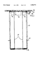
- FIG. 2 is a side view of the subject housing, in diametrical section
- FIG. 3 is an exploded view, in perspective, showing the major components of the FIG. 1 embodiment in exploded relation;
- FIG. 4 is an enlarged view of a component portion of FIG. 3.
- the multi-service floor outlet 10 comprises a cylindrical barrel portion 12 of fireproof material, preferably aluminum for weight and handling considerations.
- a flanged cap portion 14 secures a duplex power outlet 16 and four Category 5 voice/data jacks 18.
- the outer portion 20 of the bottom of barrel portion 12 is threaded.
- a removable nut 22 is mounted upon the threaded portion 20.
- a bottom closure plate 24 is shown, preferably secured by welding to the barrel portion 12.
- the plate 24 is illustrated as having four threaded apertures 25 therein, to receive electrical conduit elbows (not shown), secured in screwed relation therein.
- Removable partition means 27 having opposed plate portions provide segregated wiring paths, primarily for the conductors for the duplex power outlet 16.
- the slender flanged cap portion 14 may be installed so as to sit upon the concrete floor, the top of the outlet 10 being then substantially flush with the surface of the surrounding carpet (not shown).
- the cap portion 14 includes a circular plate 26 having offset rectangular recesses to locate voice/data jacks 18.
- An overlying plate 28 serves to locate the duplex power outlet 16.
- the plate 28 has two pairs of slots 27', by which partitions 27 may be inserted in positioned, secured relation.
- the cap portion 14 includes a first flange plate 30, which encircles the power outlet 16 and jacks 18 and is secured by screws 29 to the upper rim of barrel portion 12.
- a second flange portion of cap portion 14, plate 36 serves as a closure plate and is secured by screws to the first flange plate 30.
- the plate 36 has recesses 40, 44 in which the dual head portions of the power outlet 16, and the four jacks 18 are accommodated in flush relation.
- the outlet 10 is installed within a core-drilled through-hole, in close-fitting relation therein, being secured and effectively sealed in place by way of the flanges of cap portion 14, and the nut 22.
- the partition means 27 may be removed during installation to facilitate the introduction of the respective wiring (not shown).
Abstract
Description
Claims (7)
Priority Applications (1)
| Application Number | Priority Date | Filing Date | Title |
|---|---|---|---|
| US08/603,071 US5705772A (en) | 1996-02-20 | 1996-02-20 | Multi-service floor outlet |
Applications Claiming Priority (1)
| Application Number | Priority Date | Filing Date | Title |
|---|---|---|---|
| US08/603,071 US5705772A (en) | 1996-02-20 | 1996-02-20 | Multi-service floor outlet |
Publications (1)
| Publication Number | Publication Date |
|---|---|
| US5705772A true US5705772A (en) | 1998-01-06 |
Family
ID=24413984
Family Applications (1)
| Application Number | Title | Priority Date | Filing Date |
|---|---|---|---|
| US08/603,071 Expired - Fee Related US5705772A (en) | 1996-02-20 | 1996-02-20 | Multi-service floor outlet |
Country Status (1)
| Country | Link |
|---|---|
| US (1) | US5705772A (en) |
Cited By (41)
| Publication number | Priority date | Publication date | Assignee | Title |
|---|---|---|---|---|
| USD405052S (en) * | 1997-06-19 | 1999-02-02 | Byrne Norman R | Large lift-up with cover |
| USD405051S (en) * | 1997-06-19 | 1999-02-02 | Byrne Norman R | Lift-up with cover |
| USD406102S (en) * | 1997-06-05 | 1999-02-23 | Byrne Norman R | Double lift up device |
| USD406103S (en) * | 1997-06-09 | 1999-02-23 | Byrne Norman R | Large lift-up with power/data receptacles |
| USD420327S (en) * | 1999-01-21 | 2000-02-08 | Byrne Norman R | Lift-up with cover |
| US6028267A (en) * | 1997-04-15 | 2000-02-22 | Byrne; Norman R. | Rotatable power center system |
| US6290518B1 (en) | 1999-09-14 | 2001-09-18 | Norman R. Byrne | Rotatable power and data center with storage area |
| EP1376805A1 (en) * | 2002-06-18 | 2004-01-02 | PUK-WERKE AG, Kunststoff-Stahlverarbeitung GmbH & Co. | Under floor distribution box |
| US6696640B1 (en) | 1999-08-23 | 2004-02-24 | Walker Systems, Inc. | Quad receptacle, dual circuit flush poke-through wiring fitting with internally mountable communication/data jacks |
| US20040080903A1 (en) * | 2001-02-06 | 2004-04-29 | Byrne Norman R. | Electrical floor access module system |
| US6790084B1 (en) | 2003-09-16 | 2004-09-14 | Thomas & Betts International, Inc. | Watertight flush poke-thru cover with snap-on lids |
| US20050133235A1 (en) * | 2003-12-23 | 2005-06-23 | Wiremold, Co. | Recessed in-floor fitting |
| US20050133234A1 (en) * | 2003-12-23 | 2005-06-23 | Cole Michael T. | Spring-activated in-floor fitting |
| US20060060368A1 (en) * | 2004-09-22 | 2006-03-23 | Thomas & Betts International Inc. | Floor box cover assembly |
| US20060065423A1 (en) * | 2004-09-28 | 2006-03-30 | Rick Gesue | Compact flush-mount self-contained receptacle (SCR) |
| US20060186020A1 (en) * | 2005-02-18 | 2006-08-24 | Petroleo Brasileiro S.A. - Petrobras | Vegetable oil hydroconversion process |
| US20080053679A1 (en) * | 2006-08-29 | 2008-03-06 | Galasso Marc D | Cover for recessed electrical outlet box |
| US20080053697A1 (en) * | 2006-08-29 | 2008-03-06 | Bowman Timothy S | Recessed poke-through fitting |
| US7635110B2 (en) | 2006-08-29 | 2009-12-22 | Wiremold, Co. | Retention and mounting bracket for recessed electrical outlet box |
| US20110005799A1 (en) * | 2009-07-08 | 2011-01-13 | Thomas & Betts International, Inc. | Dual voltage electrical floor box |
| US20140224518A1 (en) * | 2013-02-13 | 2014-08-14 | Scuint Corporation | Multi-Purpose Conduit Plate |
| US8878058B2 (en) | 2012-06-28 | 2014-11-04 | Hubbell Incorporated | Raised access floor box with partitions |
| USD739821S1 (en) | 2014-04-15 | 2015-09-29 | Norman R. Byrne | Power center for a work surface |
| USD741266S1 (en) | 2014-08-21 | 2015-10-20 | Norman R. Byrne | Electrical power unit for a work surface |
| USD759596S1 (en) | 2015-02-12 | 2016-06-21 | Norman R. Byrne | Electrical power unit for a work surface |
| USD761732S1 (en) | 2015-02-06 | 2016-07-19 | Norman R. Byrne | Electrical power unit |
| USD762176S1 (en) | 2015-03-06 | 2016-07-26 | Norman R. Byrne | Electrical power unit for a work surface |
| USD762175S1 (en) | 2015-02-06 | 2016-07-26 | Norman R. Byrne | Electrical power unit for a work surface |
| US9543769B2 (en) | 2011-10-20 | 2017-01-10 | Alan Kauffmann | Pop up electrical apparatus |
| US20170063063A1 (en) * | 2015-08-28 | 2017-03-02 | The Wiremold Company | In-floor electrical fitting having cover with recessed outer flange |
| US20170063062A1 (en) * | 2015-08-25 | 2017-03-02 | Hubbell Incorporated | Floor box assembly with retainer |
| US9748709B2 (en) | 2015-03-31 | 2017-08-29 | Norman R. Byrne | Grommet-mount electrical power unit assembly |
| US10538172B2 (en) | 2017-07-06 | 2020-01-21 | Alan Kauffmann | Apparatus that automates the connecting process between a primary connector and a secondary connector for charging an electric vehicle |
| USD887363S1 (en) | 2018-01-24 | 2020-06-16 | Norman R. Byrne | Electrical power unit |
| US10770875B2 (en) | 2018-08-10 | 2020-09-08 | Norman R. Byrne | Poke-through electrical outlet assembly with leveling bezel |
| USD900034S1 (en) * | 2017-12-06 | 2020-10-27 | Premier Manufacturing Group, Inc. | Grommet assembly having electrical power receptacles for use with a work surface |
| USD900035S1 (en) | 2018-06-08 | 2020-10-27 | Norman R. Byrne | Electrical power grommet for a worksurface |
| USD905644S1 (en) | 2019-03-29 | 2020-12-22 | Norman R. Byrne | Electrical power grommet for a work surface |
| USD931817S1 (en) | 2018-06-08 | 2021-09-28 | Norman R. Byrne | Electrical power unit for a work surface |
| US11309658B2 (en) | 2018-08-13 | 2022-04-19 | Norman R. Byrne | Poke-through electrical outlet assembly with closure |
| USD954653S1 (en) | 2019-11-13 | 2022-06-14 | Norman R. Byrne | Electrical power unit for a work surface |
Citations (3)
| Publication number | Priority date | Publication date | Assignee | Title |
|---|---|---|---|---|
| US5362922A (en) * | 1992-09-30 | 1994-11-08 | Thomas & Betts Corporation | Electrical floor box divider |
| US5466886A (en) * | 1990-05-14 | 1995-11-14 | Hubbell Incorporated | Electrical outlet box assembly for power and communication wires |
| US5467565A (en) * | 1989-12-22 | 1995-11-21 | Walker Systems, Inc. | Method and apparatus for improved activation of services in an office building floor |
-
1996
- 1996-02-20 US US08/603,071 patent/US5705772A/en not_active Expired - Fee Related
Patent Citations (3)
| Publication number | Priority date | Publication date | Assignee | Title |
|---|---|---|---|---|
| US5467565A (en) * | 1989-12-22 | 1995-11-21 | Walker Systems, Inc. | Method and apparatus for improved activation of services in an office building floor |
| US5466886A (en) * | 1990-05-14 | 1995-11-14 | Hubbell Incorporated | Electrical outlet box assembly for power and communication wires |
| US5362922A (en) * | 1992-09-30 | 1994-11-08 | Thomas & Betts Corporation | Electrical floor box divider |
Cited By (64)
| Publication number | Priority date | Publication date | Assignee | Title |
|---|---|---|---|---|
| US6028267A (en) * | 1997-04-15 | 2000-02-22 | Byrne; Norman R. | Rotatable power center system |
| USD406102S (en) * | 1997-06-05 | 1999-02-23 | Byrne Norman R | Double lift up device |
| USD406103S (en) * | 1997-06-09 | 1999-02-23 | Byrne Norman R | Large lift-up with power/data receptacles |
| USD405052S (en) * | 1997-06-19 | 1999-02-02 | Byrne Norman R | Large lift-up with cover |
| USD405051S (en) * | 1997-06-19 | 1999-02-02 | Byrne Norman R | Lift-up with cover |
| USD420327S (en) * | 1999-01-21 | 2000-02-08 | Byrne Norman R | Lift-up with cover |
| US6696640B1 (en) | 1999-08-23 | 2004-02-24 | Walker Systems, Inc. | Quad receptacle, dual circuit flush poke-through wiring fitting with internally mountable communication/data jacks |
| US6720495B2 (en) | 1999-08-23 | 2004-04-13 | Walker Systems, Inc. | Quad receptacle, dual circuit flush poke-through wiring fitting with internally mountable communication/data jacks |
| US6290518B1 (en) | 1999-09-14 | 2001-09-18 | Norman R. Byrne | Rotatable power and data center with storage area |
| US20040080903A1 (en) * | 2001-02-06 | 2004-04-29 | Byrne Norman R. | Electrical floor access module system |
| US7183504B2 (en) | 2001-02-06 | 2007-02-27 | Byrne Norman R | Electrical floor access module system |
| EP1376805A1 (en) * | 2002-06-18 | 2004-01-02 | PUK-WERKE AG, Kunststoff-Stahlverarbeitung GmbH & Co. | Under floor distribution box |
| US6790084B1 (en) | 2003-09-16 | 2004-09-14 | Thomas & Betts International, Inc. | Watertight flush poke-thru cover with snap-on lids |
| US7166798B2 (en) * | 2003-12-23 | 2007-01-23 | Wiremold, Co. | Spring-activated in-floor fitting |
| US20050133235A1 (en) * | 2003-12-23 | 2005-06-23 | Wiremold, Co. | Recessed in-floor fitting |
| US20050133234A1 (en) * | 2003-12-23 | 2005-06-23 | Cole Michael T. | Spring-activated in-floor fitting |
| US7183503B2 (en) | 2003-12-23 | 2007-02-27 | Wiremold Company | Recessed in-floor fitting |
| US7064268B2 (en) | 2004-09-22 | 2006-06-20 | Thomas & Betts International, Inc. | Floor box cover assembly |
| US20060201707A1 (en) * | 2004-09-22 | 2006-09-14 | Thomas & Betts International, Inc. | Floor box cover assembly |
| US20060060368A1 (en) * | 2004-09-22 | 2006-03-23 | Thomas & Betts International Inc. | Floor box cover assembly |
| US7193160B2 (en) | 2004-09-22 | 2007-03-20 | Thomas & Betts International, Inc. | Floor box cover assembly |
| US20060065423A1 (en) * | 2004-09-28 | 2006-03-30 | Rick Gesue | Compact flush-mount self-contained receptacle (SCR) |
| US7394019B2 (en) * | 2004-09-28 | 2008-07-01 | Rick Gesue | Compact flush-mount self-contained receptacle (SCR) |
| US20060186020A1 (en) * | 2005-02-18 | 2006-08-24 | Petroleo Brasileiro S.A. - Petrobras | Vegetable oil hydroconversion process |
| US20080053697A1 (en) * | 2006-08-29 | 2008-03-06 | Bowman Timothy S | Recessed poke-through fitting |
| US20080053679A1 (en) * | 2006-08-29 | 2008-03-06 | Galasso Marc D | Cover for recessed electrical outlet box |
| US7635110B2 (en) | 2006-08-29 | 2009-12-22 | Wiremold, Co. | Retention and mounting bracket for recessed electrical outlet box |
| US8063317B2 (en) | 2006-08-29 | 2011-11-22 | Wiremold, Co. | Recessed poke-through fitting |
| US8242365B2 (en) | 2006-08-29 | 2012-08-14 | The Wiremold Company | Cover for recessed electrical outlet box |
| US20110005799A1 (en) * | 2009-07-08 | 2011-01-13 | Thomas & Betts International, Inc. | Dual voltage electrical floor box |
| US8273998B2 (en) | 2009-07-08 | 2012-09-25 | Thomas & Betts International, Inc. | Dual voltage electrical floor box |
| US9543769B2 (en) | 2011-10-20 | 2017-01-10 | Alan Kauffmann | Pop up electrical apparatus |
| US8878058B2 (en) | 2012-06-28 | 2014-11-04 | Hubbell Incorporated | Raised access floor box with partitions |
| US20140224518A1 (en) * | 2013-02-13 | 2014-08-14 | Scuint Corporation | Multi-Purpose Conduit Plate |
| US9692218B2 (en) * | 2013-02-13 | 2017-06-27 | Scuint Corporation | Multi-purpose conduit plate |
| USD739821S1 (en) | 2014-04-15 | 2015-09-29 | Norman R. Byrne | Power center for a work surface |
| USD807829S1 (en) * | 2014-08-21 | 2018-01-16 | Norman R. Byrne | Electrical power unit for a work surface |
| USD741266S1 (en) | 2014-08-21 | 2015-10-20 | Norman R. Byrne | Electrical power unit for a work surface |
| USD761732S1 (en) | 2015-02-06 | 2016-07-19 | Norman R. Byrne | Electrical power unit |
| USD816037S1 (en) | 2015-02-06 | 2018-04-24 | Norman R. Byrne | Electrical power unit for a work surface |
| USD762175S1 (en) | 2015-02-06 | 2016-07-26 | Norman R. Byrne | Electrical power unit for a work surface |
| USD849686S1 (en) | 2015-02-06 | 2019-05-28 | Norman R. Byrne | Electrical power unit |
| USD759596S1 (en) | 2015-02-12 | 2016-06-21 | Norman R. Byrne | Electrical power unit for a work surface |
| USD811337S1 (en) | 2015-02-12 | 2018-02-27 | Norman R. Byrne | Electrical power unit for a work surface |
| USD762176S1 (en) | 2015-03-06 | 2016-07-26 | Norman R. Byrne | Electrical power unit for a work surface |
| USD807297S1 (en) | 2015-03-06 | 2018-01-09 | Norman R. Byrne | Electrical power unit for a work surface |
| US9748709B2 (en) | 2015-03-31 | 2017-08-29 | Norman R. Byrne | Grommet-mount electrical power unit assembly |
| US20170063062A1 (en) * | 2015-08-25 | 2017-03-02 | Hubbell Incorporated | Floor box assembly with retainer |
| US9912134B2 (en) * | 2015-08-25 | 2018-03-06 | Hubbell Incorporated | Floor box assembly with retainer |
| US10181709B2 (en) | 2015-08-25 | 2019-01-15 | Hubbell Incorporated | Floor box assembly with retainer |
| US10069289B2 (en) * | 2015-08-28 | 2018-09-04 | The Wiremold Company | In-floor electrical fitting having cover with recessed outer flange |
| US20170063063A1 (en) * | 2015-08-28 | 2017-03-02 | The Wiremold Company | In-floor electrical fitting having cover with recessed outer flange |
| US10538172B2 (en) | 2017-07-06 | 2020-01-21 | Alan Kauffmann | Apparatus that automates the connecting process between a primary connector and a secondary connector for charging an electric vehicle |
| USD911287S1 (en) * | 2017-12-06 | 2021-02-23 | Premier Manufacturing Group, Inc. | Grommet assembly having electrical power receptacles for use with a work surface |
| USD900034S1 (en) * | 2017-12-06 | 2020-10-27 | Premier Manufacturing Group, Inc. | Grommet assembly having electrical power receptacles for use with a work surface |
| USD887363S1 (en) | 2018-01-24 | 2020-06-16 | Norman R. Byrne | Electrical power unit |
| USD900035S1 (en) | 2018-06-08 | 2020-10-27 | Norman R. Byrne | Electrical power grommet for a worksurface |
| USD931817S1 (en) | 2018-06-08 | 2021-09-28 | Norman R. Byrne | Electrical power unit for a work surface |
| US10770875B2 (en) | 2018-08-10 | 2020-09-08 | Norman R. Byrne | Poke-through electrical outlet assembly with leveling bezel |
| US11050228B2 (en) | 2018-08-10 | 2021-06-29 | Norman R. Byrne | Poke-through electrical outlet assembly with leveling bezel |
| US11309658B2 (en) | 2018-08-13 | 2022-04-19 | Norman R. Byrne | Poke-through electrical outlet assembly with closure |
| US11677178B2 (en) | 2018-08-13 | 2023-06-13 | Norman R. Byrne | Poke-through electrical assembly |
| USD905644S1 (en) | 2019-03-29 | 2020-12-22 | Norman R. Byrne | Electrical power grommet for a work surface |
| USD954653S1 (en) | 2019-11-13 | 2022-06-14 | Norman R. Byrne | Electrical power unit for a work surface |
Similar Documents
| Publication | Publication Date | Title |
|---|---|---|
| US5705772A (en) | Multi-service floor outlet | |
| US6612081B2 (en) | Water-tight cover assembly for an in-floor fitting | |
| US4443654A (en) | Flush floor fitting | |
| US6018126A (en) | Flush poke-through wiring fitting | |
| US7348487B2 (en) | Floor box with voltage divider | |
| US5195288A (en) | Floor fitting | |
| US5032690A (en) | Poke-through connector assembly | |
| US7285733B2 (en) | Recessed poke-thru fitting | |
| CA2725828C (en) | Concealed service poke-through device | |
| US5796037A (en) | Shallow recessed floor box | |
| US5467565A (en) | Method and apparatus for improved activation of services in an office building floor | |
| US3303264A (en) | Dual service conduit and outlet system | |
| US7075005B1 (en) | Electrical floor box with dual cover installation | |
| US5901512A (en) | Hardwiring race for office partitions | |
| CA2421814C (en) | Cover assembly for an in-floor fitting | |
| US5011033A (en) | Electrical service center | |
| US5243129A (en) | Flexible undercarpet power system | |
| US5828001A (en) | Plastic junction box with receptacle boxes | |
| WO2015061191A1 (en) | Integrated electrical assembly for housing modular units and related components thereof | |
| CA2215441C (en) | Multi-service floor outlet | |
| US4340772A (en) | Cover plates for electrical utility and other boxes as used in concealed wiring system of buildings | |
| EP0852839B1 (en) | Plastic junction box with receptacle boxes | |
| US6774308B1 (en) | Wire termination box assembly and associated method of installation | |
| CA2211066A1 (en) | Signal-transferring poke-through service fitting | |
| CA2211065C (en) | Signal-shielding poke-through service fitting |
Legal Events
| Date | Code | Title | Description |
|---|---|---|---|
| REMI | Maintenance fee reminder mailed | ||
| FPAY | Fee payment |
Year of fee payment: 4 |
|
| SULP | Surcharge for late payment | ||
| AS | Assignment |
Owner name: COX, WENDY, ONTARIO Free format text: ASSIGNMENT OF ASSIGNORS INTEREST;ASSIGNOR:BROWN, RANDY J.;REEL/FRAME:013138/0593 Effective date: 20010501 Owner name: DODS, LINDA, ONTARIO Free format text: ASSIGNMENT OF ASSIGNORS INTEREST;ASSIGNOR:BROWN, RANDY J.;REEL/FRAME:013138/0593 Effective date: 20010501 Owner name: DODS, TERRY, ONTARIO Free format text: ASSIGNMENT OF ASSIGNORS INTEREST;ASSIGNOR:BROWN, RANDY J.;REEL/FRAME:013138/0593 Effective date: 20010501 Owner name: DOWNEY, LINDA, ONTARIO Free format text: ASSIGNMENT OF ASSIGNORS INTEREST;ASSIGNOR:BROWN, RANDY J.;REEL/FRAME:013138/0593 Effective date: 20010501 Owner name: ERICKSON, GAIL, ONTARIO Free format text: ASSIGNMENT OF ASSIGNORS INTEREST;ASSIGNOR:BROWN, RANDY J.;REEL/FRAME:013138/0593 Effective date: 20010501 Owner name: ERICKSON, WILLIAM, ONTARIO Free format text: ASSIGNMENT OF ASSIGNORS INTEREST;ASSIGNOR:BROWN, RANDY J.;REEL/FRAME:013138/0593 Effective date: 20010501 Owner name: LAPIERRE, GUY, ONTARIO Free format text: ASSIGNMENT OF ASSIGNORS INTEREST;ASSIGNOR:BROWN, RANDY J.;REEL/FRAME:013138/0593 Effective date: 20010501 Owner name: LAPIERRE, SYLVIA, ONTARIO Free format text: ASSIGNMENT OF ASSIGNORS INTEREST;ASSIGNOR:BROWN, RANDY J.;REEL/FRAME:013138/0593 Effective date: 20010501 Owner name: LECLAIR, ELIZABETH, ONTARIO Free format text: ASSIGNMENT OF ASSIGNORS INTEREST;ASSIGNOR:BROWN, RANDY J.;REEL/FRAME:013138/0593 Effective date: 20010501 Owner name: LECLAIR, MICHAEL, ONTARIO Free format text: ASSIGNMENT OF ASSIGNORS INTEREST;ASSIGNOR:BROWN, RANDY J.;REEL/FRAME:013138/0593 Effective date: 20010501 Owner name: RALPH, JOANNE, ONTARIO Free format text: ASSIGNMENT OF ASSIGNORS INTEREST;ASSIGNOR:BROWN, RANDY J.;REEL/FRAME:013138/0593 Effective date: 20010501 |
|
| FPAY | Fee payment |
Year of fee payment: 8 |
|
| AS | Assignment |
Owner name: DODS, TERRY, ONTARIO Free format text: ASSIGNMENT OF ASSIGNORS INTEREST;ASSIGNOR:BROWN, RANDY J., MR.;REEL/FRAME:021194/0849 Effective date: 20080229 Owner name: DODS, LINDA, ONTARIO Free format text: ASSIGNMENT OF ASSIGNORS INTEREST;ASSIGNOR:BROWN, RANDY J., MR.;REEL/FRAME:021194/0849 Effective date: 20080229 Owner name: RALPH, JOANNE, ONTARIO Free format text: ASSIGNMENT OF ASSIGNORS INTEREST;ASSIGNOR:BROWN, RANDY J., MR.;REEL/FRAME:021194/0849 Effective date: 20080229 Owner name: COX, WENDY, ONTARIO Free format text: ASSIGNMENT OF ASSIGNORS INTEREST;ASSIGNOR:BROWN, RANDY J., MR.;REEL/FRAME:021194/0849 Effective date: 20080229 Owner name: DOWNEY, LINDA, ONTARIO Free format text: ASSIGNMENT OF ASSIGNORS INTEREST;ASSIGNOR:BROWN, RANDY J., MR.;REEL/FRAME:021194/0849 Effective date: 20080229 Owner name: LAPIERRE, GUY, ONTARIO Free format text: ASSIGNMENT OF ASSIGNORS INTEREST;ASSIGNOR:BROWN, RANDY J., MR.;REEL/FRAME:021194/0849 Effective date: 20080229 Owner name: LECLAIR, ELIZABETH, ONTARIO Free format text: ASSIGNMENT OF ASSIGNORS INTEREST;ASSIGNOR:BROWN, RANDY J., MR.;REEL/FRAME:021194/0849 Effective date: 20080229 Owner name: ERICKSON, WILLIAM, ONTARIO Free format text: ASSIGNMENT OF ASSIGNORS INTEREST;ASSIGNOR:BROWN, RANDY J., MR.;REEL/FRAME:021194/0849 Effective date: 20080229 Owner name: ERICKSON, GAIL, ONTARIO Free format text: ASSIGNMENT OF ASSIGNORS INTEREST;ASSIGNOR:BROWN, RANDY J., MR.;REEL/FRAME:021194/0849 Effective date: 20080229 Owner name: LECLAIR, MICHAEL, ONTARIO Free format text: ASSIGNMENT OF ASSIGNORS INTEREST;ASSIGNOR:BROWN, RANDY J., MR.;REEL/FRAME:021194/0849 Effective date: 20080229 Owner name: LAPIERRE, SYLVIA, ONTARIO Free format text: ASSIGNMENT OF ASSIGNORS INTEREST;ASSIGNOR:BROWN, RANDY J., MR.;REEL/FRAME:021194/0849 Effective date: 20080229 |
|
| REMI | Maintenance fee reminder mailed | ||
| LAPS | Lapse for failure to pay maintenance fees | ||
| STCH | Information on status: patent discontinuation |
Free format text: PATENT EXPIRED DUE TO NONPAYMENT OF MAINTENANCE FEES UNDER 37 CFR 1.362 |
|
| FP | Expired due to failure to pay maintenance fee |
Effective date: 20100106 |
|
| AS | Assignment |
Owner name: NOCOM INC., CANADA Free format text: ASSIGNMENT OF ASSIGNORS INTEREST;ASSIGNOR:MULTICONNECT OUTLETS INCORPORATED;REEL/FRAME:025039/0018 Effective date: 20100531 |