US5711135A - Heat-shrinkable band application machine - Google Patents
Heat-shrinkable band application machine Download PDFInfo
- Publication number
- US5711135A US5711135A US08/604,459 US60445996A US5711135A US 5711135 A US5711135 A US 5711135A US 60445996 A US60445996 A US 60445996A US 5711135 A US5711135 A US 5711135A
- Authority
- US
- United States
- Prior art keywords
- band
- plunger
- target container
- transfer surface
- application machine
- Prior art date
- Legal status (The legal status is an assumption and is not a legal conclusion. Google has not performed a legal analysis and makes no representation as to the accuracy of the status listed.)
- Expired - Lifetime
Links
- 230000007246 mechanism Effects 0.000 claims abstract description 30
- 238000000034 method Methods 0.000 claims description 11
- 238000011144 upstream manufacturing Methods 0.000 claims 11
- 230000009471 action Effects 0.000 description 1
- 230000001154 acute effect Effects 0.000 description 1
- 238000004080 punching Methods 0.000 description 1
- 230000004044 response Effects 0.000 description 1
- 230000011664 signaling Effects 0.000 description 1
Images


Classifications
-
- B—PERFORMING OPERATIONS; TRANSPORTING
- B65—CONVEYING; PACKING; STORING; HANDLING THIN OR FILAMENTARY MATERIAL
- B65B—MACHINES, APPARATUS OR DEVICES FOR, OR METHODS OF, PACKAGING ARTICLES OR MATERIALS; UNPACKING
- B65B9/00—Enclosing successive articles, or quantities of material, e.g. liquids or semiliquids, in flat, folded, or tubular webs of flexible sheet material; Subdividing filled flexible tubes to form packages
- B65B9/10—Enclosing successive articles, or quantities of material, in preformed tubular webs, or in webs formed into tubes around filling nozzles, e.g. extruded tubular webs
- B65B9/13—Enclosing successive articles, or quantities of material, in preformed tubular webs, or in webs formed into tubes around filling nozzles, e.g. extruded tubular webs the preformed tubular webs being supplied in a flattened state
-
- B—PERFORMING OPERATIONS; TRANSPORTING
- B65—CONVEYING; PACKING; STORING; HANDLING THIN OR FILAMENTARY MATERIAL
- B65B—MACHINES, APPARATUS OR DEVICES FOR, OR METHODS OF, PACKAGING ARTICLES OR MATERIALS; UNPACKING
- B65B7/00—Closing containers or receptacles after filling
- B65B7/16—Closing semi-rigid or rigid containers or receptacles not deformed by, or not taking-up shape of, contents, e.g. boxes or cartons
- B65B7/28—Closing semi-rigid or rigid containers or receptacles not deformed by, or not taking-up shape of, contents, e.g. boxes or cartons by applying separate preformed closures, e.g. lids, covers
- B65B7/2842—Securing closures on containers
- B65B7/2885—Securing closures on containers by heat-shrinking
Definitions
- the present invention relates to machines for applying heat-shrinkable bands to containers, and more particularly to a method and apparatus for precisely positioning bands onto containers being conveyed past a band application point.
- a band application machine includes a transfer mechanism capable of repeatedly transferring cut bands to containers passing a band application point.
- Transfer mechanisms of prior art machines are typically designed to only handle a very limited size range of bands.
- versatility and effectiveness of prior art band application machines are severely limited due to their inability to handle a wide range of different size bands.
- a business needing to place different size bands on containers may have to purchase several band application machines to handle the different sized bands.
- a business with a single type of machine may have to redesign or rework a machine if they decide to apply different size bands to containers.
- the present invention has been designed to overcome the problems of prior art banding machines discussed above. More particularly, the band application machine of the present invention includes a transfer mechanism capable of transferring to containers both small and large diameter bands and bands having depths of various lengths.
- the band application machine of the present invention includes a transfer mechanism having a cut bane gripping mechanism.
- the band gripping mechanism includes suction cups that are movably mounted. The suction cups are laterally moveable from a position where a closed band is gripped on opposing sides to a position where the band is open and laterally aligned with the stroke of a plunger positioned above the band.
- the ability of the transfer mechanism to grip the band on opposing sides and to laterally position the band enables the machine to handle a wide range of different size bands.
- the plunger is positioned over the opened band at an angle with respect to the band.
- the plunger presses and drives the band onto a container as the band gripping mechanism releases the open band.
- the angle of the top plunger with respect to the cut band results in the plunger engaging a leading edge of the cut band as the plunger moves to press the band onto the under passing container.
- an air blast means that directs air against an inner trailing section of the band as the plunger presses the band onto the container so as to effectively urge and maintain the band in an open position.
- Another object of the present invention is to provide a band application machine that consistently applies bands to containers.
- Another object of the present invention is to provide a band application machine that can precisely handle a wide range of different size bands and transfer the bands to containers.
- Another object of the present invention is to provide a band application machine that is easily adjustable to allow application of a wide range of different size bands without extensive redesigned or reworking of the machine.
- Another object of the present invention is to provide a band application machine that is versatile, easy to use, and easy to maintain.
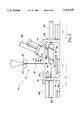
- FIGS. 1-5 are a sequence of side views of the band application machine showing the band transfer system applying a band to a container.
- FIG. 5A, 5B and 5C are a sequence of views illustrating the final stages of the transfer of a cut band onto an underpassing container.
- FIG. 6 is a perspective view of the plunger of the band application machine showing the plunger's air blast orifices.
- FIG. 7 is a schematic of the control system of the band application machine.
- the present invention relates to an improved machine for applying heat-shrinkable bands to containers.
- Machines for applying heat-shrinkable bands are well-known in the prior art and are used throughout the world for applying cut, tamper-evident bands and labels to a wide variety of containers. Therefore, in describing the band application machine of the present invention, it will be appreciated that much of the structure and function of the machine is conventional. For that reason, a detailed description of the entire machine will not be dealt with herein.
- U.S. Pat. Nos. 5,165,215; 4,914,893; 2,623,673; 2,751,735; and 3,802,152 the disclosures of each being expressly incorporated herein by reference.
- the present invention is directed to a band transfer system of a band application machine, where the band transfer system transfers cut bands from a cutting site to underlying passing containers.
- Band application machine 10 includes four basic systems, a feed system 12, a cutting system 14, a band transfer system 16, and a control system 20. Briefly viewing each of the systems before proceeding with the detailed description of the invention, it should be pointed out that the feed system 12 functions to direct and advance an elongated, supply strip of band material 24 to the cutting system 14. Cutting system 14 cuts the supply strip 24 into individual cut bands 24a that are ultimately applied to containers. Once cut, each cut band 24a is engaged by the band transfer system 16. Band transfer system 16 functions to grasp the cut band 24a and to position the same for an efficient transfer onto a passing container C. All of he aforementioned systems are connected to and controlled by a conventional control system 20. (See FIG. 7).
- Feed system 12 includes a pair of feed rollers 22 and a step motor (not shown) for selectively rotating feed rollers 22.
- Supply strip 24 is threaded through feed rollers 22 and is gripped therebetween. By rotating feed rollers 22, a selected length of supply strip 24 is fed to cutting system 14.
- Cutting system 14 is disposed below feed rollers 22 and functions to cut the supply strip 24 being fed downwardly from feed rollers 22.
- Cutting system 14 includes a blade 30 that is connected to an air cylinder 28 and is moveable between a retracted position shown in FIG. 1 and an extended position shown in FIG. 2. Blade 30 cuts supply strip 24 to produce a cut band 24a as blade 30 moves from the retracted position to the extended position.
- Transfer system 16 functions to grasp the cut band 24a and to effectuate transfer of the cut band 24a onto an underlying, passing container C that is disposed on a conveyor system 65.
- band transfer system 16 includes a band-gripping mechanism 32 and a plunger 34.
- Band gripping mechanism 32 functions to grip and open the cut band 24a, while also laterally positioning the cut band 24a beneath plunger 34.
- Plunger 34 functions to press the cut band 24a onto passing container c.
- Band gripping mechanism 32 includes a first gripper cylinder 36 having a suction-cup block 42 attached to the cylinder's piston 40.
- Band gripping mechanism 32 also includes a second gripper cylinder 44 which opposes first gripper cylinder 36.
- Second gripper cylinder 44 also includes a suction-cup block 50 connected to the piston 46 of gripper cylinder 44.
- Opposing gripper cylinders 36 and 44 each have an angled block face, 52 and 54 respectively. In the preferred embodiment, block faces 52 and 54 are parallel to one another and are disposed at approximately a 25°-30° angle. Block faces 52 and 54 each have a suction cup, 56 and 60 respectively, attached thereto.
- Suction cups 56 and 60 are connected to a vacuum source (not shown) that draws air through the suction cups 56 and 60 to produce a vacuum securing the cut band 24a to suction cups 56 and 60 when cut band 24a is positioned against suction cups 56 and 60.
- a vacuum source not shown
- gripper cylinders 36 and 44 are selectively actuated to open cut band 24a and position band 24a beneath plunger 34.
- block faces 52 and 54 each have only a single suction cup 56 and 60 respectively.
- a plurality of spaced suction cups can be provided on each block face 52 and 54 so that the suction cups grasp a band along multiple points on each side of the band. Gripping a cut band with a plurality of suction cups along opposing sides provides more effective handling of large diameter bands or deep bands.
- plunger 34 functions to press cut band 24a, positioned beneath it by gripping mechanism 32, onto a passing container C.
- plunger 34 reciprocates between a retracted position shown in FIGS. 1 and 2 to an extended position shown in FIG. 5 where plunger 34 presses cut band 24a onto a passing container C.
- Plunger 34 includes a plunger cylinder 66 and a plate 72 attached to piston 70 of cylinder 66.
- plate 72 includes a plate face 74 having a pair of elongated channels 76 and an orifice 80 located within each channel 76.
- Orifices 80 are positioned at an acute angle with respect to the plate face 74 and are connected to a pressurized air source (not shown) that selectively forces an air blast from orifices 80.
- Channels 76 help direct the air blasts from orifices 80 in a direction downstream of the passing containers C.
- control system 20 is a programmable controller 82 connected to the feed mechanism 12, cutting mechanism 14, and transfer system 16. Controller 82 receives input from the various systems and directs the operation of feed system 12, cutting system 14 and transfer system 16. Control system 20 includes various switches connected to controller 82 for sensing selected conditions of the band application machine 10 and signalling programmable controller 82 of these selected conditions. Control system 20 will be described in more detail in the following discussion of the operation of band application machine 10.
- band application machine 10 Operation of band application machine 10 is controlled by control system 20.
- Band application machine 10 operates in cycles with each cycle beginning with the feeding of the supply strip 24 and ending with a complete engagement of a cut band 24a with a container C. A description of a single cycle follows.
- band application machine 10 is positioned as shown in FIG. 1.
- Controller 82 signals the step motor (not shown) attached to rollers 22 to advance supply strip 24 downwardly such that a predetermined length of band material 24 extends below blade 30.
- a sensor switch (not shown) associated with feed mechanism 12 signals controller 82 that supply strip 24 has been advanced the selected distance, and in response controller 82 directs the operation of band gripping mechanism 32 as follows.
- gripper cylinder 44 is actuated to place piston 46 in an extended position such that suction-cup block 50 is positioned adjacent a side section of supply strip 24.
- a sensor switch (not shown) associated with gripper cylinder 44 produces a signal representing this condition and sends this signal to controller 82.
- controller 82 directs gripper cylinder 36 to position suction-cup block 42 to a partially-extended position where suction-cup block 42 is positioned adjacent to supply strip 24 and opposing suction-cup block 50.
- controller 82 Upon receiving the signal that the supply strip 24 has been advanced, controller 82 also directs the vacuum source (not shown) to draw air through suction cups 56 and 60.
- the vacuum source not shown
- suction cups 56 and 60 When opposing suction-cup blocks 42 and 50 are positioned adjacent to one another as shown in FIG. 2, a vacuum is produced at suction cups 56 and 60 which causes opposing sides of cut band 24a to be gripped by suction cups 56 and 60.
- a sensor switch (not shown) associated with gripper cylinder 44 signals controller 82 of this condition.
- controller 82 directs cutting mechanism 14 to extend blade 30 from its retracted position (shown in FIG. 1) to its extended position (shown in FIG. 2).
- blade 30 is moved to the extended position, it crosses the path of supply strip 24 to produce the cut band 24a.
- blade 30 is moved back into its retracted position.
- a sensor switch associated with cutting mechanism 14 signals controller 82 of this condition.
- controller 82 directs gripper cylinder 44 to move suction-cup block 50 into a retracted position which also directs gripper cylinder 36 to move suction-cup block 42 to a fully extended position.
- gripper cylinder 44 As gripper cylinder 44 is moved into its retracted position and gripper cylinder 36 is positioned to its fully extended position, cut band 24a which is gripped between block faces 52 and 54 is moved from a closed position into an open position.
- band 24a is laterally moved from a cutting and band supply area to a location beneath plunger 34. The lateral movement of band 24a is necessary to provide clearance for plunger 34 such that the stroke of plunger 34 is not hindered by cutting system 14 or feed system 12.
- a sensor switch (not shown) associated with gripper cylinder 36 signals controller 82 when gripper cylinder 36 is moved into its fully extended position. Upon receiving this signal, controller 82 directs the vacuum source (not shown) to release the vacuum at suction cups 56 and 60 such that cut band 24a is released from band gripper mechanism 32. After the vacuum is released, opposing gripper cylinders 36 and 44 are directed to move into their initial retracted positions.
- plunger 34 is signaled to move to the extended position by a sensor switch which (not shown) is associated with conveyor system 65 and which indicates the position of container C on conveyor 65.
- the path of plunger 34 is aligned with the cut band 24a such that the band 24a is pressed onto container C (see FIG. 5A, 5B and 5C) passing below.
- a sensor switch which (not shown) is associated with conveyor system 65 and which indicates the position of container C on conveyor 65.
- the path of plunger 34 is aligned with the cut band 24a such that the band 24a is pressed onto container C (see FIG. 5A, 5B and 5C) passing below.
- angled face 74 initially contacts the leading edge of cut band 24a.
- Band 24a is then pushed into an angled position corresponding to the angle of plate face 74.
- the pressurized air source (not shown) also directs a blast of air through orifices 80.
- the blast of air is directed downwardly against an inside, trailing-edge section of cut band 24a.
- the blast of air helps force and maintain the trailing-edge section of band 24a in an open position to help ensure that cut band 24a remains in an open position and is properly positioned over container C as the plunger 34 presses cut band 24a onto container C. If the cut band 24a is not positioned properly over a container C or is inadvertently moved toward a closed position, cut band 24a may be pressed against the top of passing container C and not be pressed over and onto container C.
- the blast of air from orifices 80 helps ensure that cut band 24a is maintained in the open position and properly positioned. In addition, the blast of air helps ensure that the trailing edge of band 24a is not snagged on imperfections or irregularities on the surface of the top of container C.
- the timing of plunger 34 is also adjustable to ensure that cut band 24a is properly pressed onto a passing container C.
- controller 82 is programmable such that plunger 34 is maintained in its extended position for a relatively extended time period such that cut band 24a is gradually pressed onto a container C. See FIGS. 5A-5C. Due to the large size of a band 24a corresponding to a large diameter container C, such a band 24a cannot be fully punched onto the container C as plunger 34 initially reaches its extended position. Instead, the plunger 34 is held in its extended position so that the band 24a is gradually pressed onto container C as container C advances beneath plunger 34.
- bands 24a can be fully punched onto a container C as plunger 34, initially reaches its extended position.
- controller 82 is programmed such that plunger 34 stays in an extended position only momentarily. This is accomplished by a simple punching action.
- plate 72 of plunger 34 is re-positioned into its initial, retracted position. The band application cycle is completed and ready for a subsequent cycle once plunger 34 is moved to the retracted position.
- the band application machine 10 of the present invention provides a band transfer system 16 that enables a cut band 24a to be more effectively gripped, positioned, and placed onto a passing container C.
- Band transfer system 16 and controller 82 enables band application machine 10 to handle both small and large diameter bands and bands having depths of various lengths, without the need for extensive redesigning or reworking the band application machine 10 to accommodate different-size bands.
- Band application machine 10 is also easily adjustable to allow consistent and precise application of different-sized bands.
Abstract
Description
Claims (21)
Priority Applications (1)
| Application Number | Priority Date | Filing Date | Title |
|---|---|---|---|
| US08/604,459 US5711135A (en) | 1993-03-15 | 1996-02-21 | Heat-shrinkable band application machine |
Applications Claiming Priority (3)
| Application Number | Priority Date | Filing Date | Title |
|---|---|---|---|
| US08/031,314 US5305578A (en) | 1993-03-15 | 1993-03-15 | Heat-shrinkable band application machine |
| US08/232,774 US5495704A (en) | 1993-03-15 | 1994-04-25 | Heat-shrinkable band application machine |
| US08/604,459 US5711135A (en) | 1993-03-15 | 1996-02-21 | Heat-shrinkable band application machine |
Related Parent Applications (1)
| Application Number | Title | Priority Date | Filing Date |
|---|---|---|---|
| US08/232,774 Division US5495704A (en) | 1993-03-15 | 1994-04-25 | Heat-shrinkable band application machine |
Publications (1)
| Publication Number | Publication Date |
|---|---|
| US5711135A true US5711135A (en) | 1998-01-27 |
Family
ID=21858767
Family Applications (3)
| Application Number | Title | Priority Date | Filing Date |
|---|---|---|---|
| US08/031,314 Expired - Lifetime US5305578A (en) | 1993-03-15 | 1993-03-15 | Heat-shrinkable band application machine |
| US08/232,774 Expired - Lifetime US5495704A (en) | 1993-03-15 | 1994-04-25 | Heat-shrinkable band application machine |
| US08/604,459 Expired - Lifetime US5711135A (en) | 1993-03-15 | 1996-02-21 | Heat-shrinkable band application machine |
Family Applications Before (2)
| Application Number | Title | Priority Date | Filing Date |
|---|---|---|---|
| US08/031,314 Expired - Lifetime US5305578A (en) | 1993-03-15 | 1993-03-15 | Heat-shrinkable band application machine |
| US08/232,774 Expired - Lifetime US5495704A (en) | 1993-03-15 | 1994-04-25 | Heat-shrinkable band application machine |
Country Status (1)
| Country | Link |
|---|---|
| US (3) | US5305578A (en) |
Cited By (6)
| Publication number | Priority date | Publication date | Assignee | Title |
|---|---|---|---|---|
| US6263940B1 (en) | 1999-04-21 | 2001-07-24 | Axon Corporation | In-line continuous feed sleeve labeling machine and method |
| US6996954B1 (en) | 2003-12-18 | 2006-02-14 | Axon Corporation | Horizontal sleeve applicator and method |
| US10287045B2 (en) | 2015-12-30 | 2019-05-14 | Axon Llc | Shrink sleeve applicator and related roller conveyor arrangement |
| US10640253B2 (en) | 2016-11-21 | 2020-05-05 | Axon Llc | Tubular banding applicator and method |
| US11299382B2 (en) | 2020-06-02 | 2022-04-12 | Axon Llc | System and method for applying tubular tamper evident bands to containers |
| US11390408B2 (en) | 2020-11-24 | 2022-07-19 | Axon Llc | System and method for applying tubular bands to containers utilizing angled band ejection |
Families Citing this family (8)
| Publication number | Priority date | Publication date | Assignee | Title |
|---|---|---|---|---|
| US5305578A (en) * | 1993-03-15 | 1994-04-26 | Axon Corporation | Heat-shrinkable band application machine |
| US5657616A (en) * | 1996-01-18 | 1997-08-19 | Elsner Engineering Works, Inc. | Roll wrapping machine with roll orienter and method |
| US20040118904A1 (en) * | 2002-12-19 | 2004-06-24 | Sonoco Development, Inc. | Composite container having a hermetically sealed polymeric sleeve |
| US7472584B2 (en) * | 2003-12-22 | 2009-01-06 | Eastman Chemical Company | Device to measure the solidification properties of a liquid film and method therefor |
| US7156140B1 (en) | 2004-06-08 | 2007-01-02 | Axon Corporation | Heat-shrinkable banding apparatus and method |
| US20060075861A1 (en) * | 2004-10-07 | 2006-04-13 | Flooding Daniel L | Film cutter |
| US7849770B2 (en) * | 2004-10-07 | 2010-12-14 | Douglas Machine, Inc. | Film cutter |
| CA2664485C (en) * | 2006-10-27 | 2015-07-14 | Busse/Sji Corporation | Strap removal system |
Citations (8)
| Publication number | Priority date | Publication date | Assignee | Title |
|---|---|---|---|---|
| US2976661A (en) * | 1957-08-16 | 1961-03-28 | Albro Fillers & Engineering Co | Devices for applying sealing bands to articles |
| US3888067A (en) * | 1973-09-18 | 1975-06-10 | Gilbreth Co | Banding machine |
| US4184309A (en) * | 1978-08-02 | 1980-01-22 | Owens-Illinois, Inc. | Method and apparatus for assemblying tubular sleeve preforms and containers |
| US4293364A (en) * | 1978-09-14 | 1981-10-06 | Fuji Seal Industry Co., Ltd. | Method and machine for opening up a cylindrical film tube and fitting it over an object |
| US4357788A (en) * | 1979-03-09 | 1982-11-09 | Owens-Illinois, Inc. | Method and apparatus for assembling tubular sleeve preforms and containers |
| US4914893A (en) * | 1988-02-26 | 1990-04-10 | Strub Eric W | Large size container banding apparatus |
| US5070680A (en) * | 1990-05-31 | 1991-12-10 | Fuji Seal Industry Co. Ltd. | Apparatus for opening a flat tube and fitting same on a container or the like |
| US5101613A (en) * | 1990-05-21 | 1992-04-07 | Wilhelm Thomas K | Apparatus for positioning and shaping a tubular member over a container |
Family Cites Families (1)
| Publication number | Priority date | Publication date | Assignee | Title |
|---|---|---|---|---|
| US5305578A (en) * | 1993-03-15 | 1994-04-26 | Axon Corporation | Heat-shrinkable band application machine |
-
1993
- 1993-03-15 US US08/031,314 patent/US5305578A/en not_active Expired - Lifetime
-
1994
- 1994-04-25 US US08/232,774 patent/US5495704A/en not_active Expired - Lifetime
-
1996
- 1996-02-21 US US08/604,459 patent/US5711135A/en not_active Expired - Lifetime
Patent Citations (8)
| Publication number | Priority date | Publication date | Assignee | Title |
|---|---|---|---|---|
| US2976661A (en) * | 1957-08-16 | 1961-03-28 | Albro Fillers & Engineering Co | Devices for applying sealing bands to articles |
| US3888067A (en) * | 1973-09-18 | 1975-06-10 | Gilbreth Co | Banding machine |
| US4184309A (en) * | 1978-08-02 | 1980-01-22 | Owens-Illinois, Inc. | Method and apparatus for assemblying tubular sleeve preforms and containers |
| US4293364A (en) * | 1978-09-14 | 1981-10-06 | Fuji Seal Industry Co., Ltd. | Method and machine for opening up a cylindrical film tube and fitting it over an object |
| US4357788A (en) * | 1979-03-09 | 1982-11-09 | Owens-Illinois, Inc. | Method and apparatus for assembling tubular sleeve preforms and containers |
| US4914893A (en) * | 1988-02-26 | 1990-04-10 | Strub Eric W | Large size container banding apparatus |
| US5101613A (en) * | 1990-05-21 | 1992-04-07 | Wilhelm Thomas K | Apparatus for positioning and shaping a tubular member over a container |
| US5070680A (en) * | 1990-05-31 | 1991-12-10 | Fuji Seal Industry Co. Ltd. | Apparatus for opening a flat tube and fitting same on a container or the like |
Cited By (6)
| Publication number | Priority date | Publication date | Assignee | Title |
|---|---|---|---|---|
| US6263940B1 (en) | 1999-04-21 | 2001-07-24 | Axon Corporation | In-line continuous feed sleeve labeling machine and method |
| US6996954B1 (en) | 2003-12-18 | 2006-02-14 | Axon Corporation | Horizontal sleeve applicator and method |
| US10287045B2 (en) | 2015-12-30 | 2019-05-14 | Axon Llc | Shrink sleeve applicator and related roller conveyor arrangement |
| US10640253B2 (en) | 2016-11-21 | 2020-05-05 | Axon Llc | Tubular banding applicator and method |
| US11299382B2 (en) | 2020-06-02 | 2022-04-12 | Axon Llc | System and method for applying tubular tamper evident bands to containers |
| US11390408B2 (en) | 2020-11-24 | 2022-07-19 | Axon Llc | System and method for applying tubular bands to containers utilizing angled band ejection |
Also Published As
| Publication number | Publication date |
|---|---|
| US5495704A (en) | 1996-03-05 |
| US5305578A (en) | 1994-04-26 |
Similar Documents
| Publication | Publication Date | Title |
|---|---|---|
| US5711135A (en) | Heat-shrinkable band application machine | |
| DE69936949T2 (en) | Device for handling and packaging brittle tablets | |
| US4412876A (en) | Labeling apparatus | |
| US4293364A (en) | Method and machine for opening up a cylindrical film tube and fitting it over an object | |
| US5358232A (en) | Method and device for producing defined stacks of folded or unfolded sheets | |
| US3430409A (en) | Automatic bag opener | |
| US3733773A (en) | Apparatus including reciprocating web feeding means for a continuously feeding web | |
| GB2052436A (en) | Labelling apparatus | |
| JPS61111900A (en) | Method and device for cutting and peeling elastic band | |
| EP0478868B1 (en) | Apparatus for opening a flat tube and fitting same on a container or the like | |
| GB2184086A (en) | Blister pack apparatus and feeder apparatus | |
| US5423649A (en) | Apparatus for cutting and removing package material | |
| GB1401914A (en) | Handle attaching machines | |
| EP0390230A2 (en) | Method and apparatus for attaching together a plurality of articles | |
| US4662149A (en) | Table-top apparatus and method for forming sealing packages | |
| CA2168515A1 (en) | Device for Rapidly Feeding Sheet Inserts to a Pusher Conveyor of a Packaging Machine | |
| GB940329A (en) | Method and apparatus for producing hollow articles of thermo-plastic | |
| JPH08252740A (en) | Material feeding device | |
| ES2029276T3 (en) | CONCAVE PARTS FEEDING APPARATUS IN A PRODUCTION LINE. | |
| US3708950A (en) | Mechanical means to apply a plastic template to the necks of containers | |
| US3296907A (en) | Tape cutting apparatus | |
| US2677477A (en) | Method and apparatus for applying labels | |
| US5448876A (en) | Machine for applying heat shrinkable bands to containers | |
| US4911601A (en) | Device for moving and supporting a stack of folded cartons in carton automatic feeding device for a liquid filling machine | |
| US5165215A (en) | Machine for applying tamper evident bands to container |
Legal Events
| Date | Code | Title | Description |
|---|---|---|---|
| STCF | Information on status: patent grant |
Free format text: PATENTED CASE |
|
| AS | Assignment |
Owner name: AXON CORPORATION, A NORTH CAROLINA CORPORATION, NO Free format text: ASSIGNMENT OF ASSIGNORS INTEREST;ASSIGNOR:MENAYAN, VICTOR V.;REEL/FRAME:009817/0759 Effective date: 19990308 |
|
| AS | Assignment |
Owner name: LASALLE NATIONAL BANK, ILLINOIS Free format text: AMENDED AND RESTATED PATENT AND LICENSE SECURITY AGREEMENT;ASSIGNORS:PROMACH, INC.;BRENTON ENGINEERING COMPANY, A MINNESOTA CORPORATION;ROBERTS POLYPRO, INC., A SOUTH CAROLINA CORPORATION;AND OTHERS;REEL/FRAME:010164/0898 Effective date: 19990611 |
|
| FPAY | Fee payment |
Year of fee payment: 4 |
|
| FEPP | Fee payment procedure |
Free format text: PAYOR NUMBER ASSIGNED (ORIGINAL EVENT CODE: ASPN); ENTITY STATUS OF PATENT OWNER: LARGE ENTITY |
|
| AS | Assignment |
Owner name: AXON CORPORATION, GEORGIA Free format text: RELEASE OF SECURITY INTEREST;ASSIGNOR:LALALLE BANK NATIONAL ASSOCIATION;REEL/FRAME:014709/0862 Effective date: 20031121 Owner name: BRENTON ENGINEERING COMPANY, GEORGIA Free format text: RELEASE OF SECURITY INTEREST;ASSIGNOR:LALALLE BANK NATIONAL ASSOCIATION;REEL/FRAME:014709/0862 Effective date: 20031121 Owner name: ORION PACKAGING SYSTEMS, INC., GEORGIA Free format text: RELEASE OF SECURITY INTEREST;ASSIGNOR:LALALLE BANK NATIONAL ASSOCIATION;REEL/FRAME:014709/0862 Effective date: 20031121 Owner name: PRO MACH, INC., GEORGIA Free format text: RELEASE OF SECURITY INTEREST;ASSIGNOR:LALALLE BANK NATIONAL ASSOCIATION;REEL/FRAME:014709/0862 Effective date: 20031121 Owner name: ROBERTS POLYPRO, INC., GEORGIA Free format text: RELEASE OF SECURITY INTEREST;ASSIGNOR:LALALLE BANK NATIONAL ASSOCIATION;REEL/FRAME:014709/0862 Effective date: 20031121 Owner name: WACHOVIA BANK, NATIONAL ASSOCIATION, NORTH CAROLIN Free format text: SECURITY INTEREST;ASSIGNOR:AXON CORPORATION;REEL/FRAME:014734/0845 Effective date: 20031121 Owner name: WEXXAR CORPORATION, THE, GEORGIA Free format text: RELEASE OF SECURITY INTEREST;ASSIGNOR:LALALLE BANK NATIONAL ASSOCIATION;REEL/FRAME:014709/0862 Effective date: 20031121 |
|
| FEPP | Fee payment procedure |
Free format text: PAYER NUMBER DE-ASSIGNED (ORIGINAL EVENT CODE: RMPN); ENTITY STATUS OF PATENT OWNER: LARGE ENTITY |
|
| FEPP | Fee payment procedure |
Free format text: PAYOR NUMBER ASSIGNED (ORIGINAL EVENT CODE: ASPN); ENTITY STATUS OF PATENT OWNER: LARGE ENTITY |
|
| AS | Assignment |
Owner name: JPMORGAN CHASE BANK, N.A., AS ADMINISTRATIVE AGENT Free format text: SECURITY AGREEMENT;ASSIGNOR:AXON CORPORATION;REEL/FRAME:015698/0251 Effective date: 20041214 |
|
| FPAY | Fee payment |
Year of fee payment: 8 |
|
| AS | Assignment |
Owner name: AXON CORPORATION, NORTH CAROLINA Free format text: ASSIGNMENT OF ASSIGNORS INTEREST;ASSIGNOR:WACHOVIA BANK, NATIONAL ASSOCIATION;REEL/FRAME:016172/0052 Effective date: 20041214 |
|
| FEPP | Fee payment procedure |
Free format text: PAYER NUMBER DE-ASSIGNED (ORIGINAL EVENT CODE: RMPN); ENTITY STATUS OF PATENT OWNER: LARGE ENTITY Free format text: PAYOR NUMBER ASSIGNED (ORIGINAL EVENT CODE: ASPN); ENTITY STATUS OF PATENT OWNER: LARGE ENTITY |
|
| AS | Assignment |
Owner name: AXON LLC, NORTH CAROLINA Free format text: CONVERSION TO LLC/CHANGE OF NAME;ASSIGNOR:AXON CORPORATION;REEL/FRAME:020741/0985 Effective date: 20070430 |
|
| FPAY | Fee payment |
Year of fee payment: 12 |
|
| AS | Assignment |
Owner name: AXON CORPORATION, OHIO Free format text: TERMINATION AND RELEASE OF SECURITY INTEREST IN PATENT RIGHTS;ASSIGNOR:JPMORGAN CHASE BANK, N.A., AS ADMINISTRATIVE AGENT;REEL/FRAME:026552/0263 Effective date: 20110706 |
|
| AS | Assignment |
Owner name: BARCLAYS BANK PLC, NEW YORK Free format text: SECURITY AGREEMENT;ASSIGNORS:PRO MACH HOLDINGS, INC.;ALLPAX PRODUCTS LLC;AXON LLC;AND OTHERS;REEL/FRAME:026561/0252 Effective date: 20110706 |
|
| AS | Assignment |
Owner name: PMI EXPORT CORPORATION, OHIO Free format text: TERMINATION OF SECURITY INTEREST IN PATENTS;ASSIGNOR:BARCLAYS BANK PLC;REEL/FRAME:034066/0379 Effective date: 20141022 Owner name: AXON LLC, OHIO Free format text: TERMINATION OF SECURITY INTEREST IN PATENTS;ASSIGNOR:BARCLAYS BANK PLC;REEL/FRAME:034066/0379 Effective date: 20141022 Owner name: PRO MACH HOLDINGS, INC., OHIO Free format text: TERMINATION OF SECURITY INTEREST IN PATENTS;ASSIGNOR:BARCLAYS BANK PLC;REEL/FRAME:034066/0379 Effective date: 20141022 Owner name: FOWLER PRODUCTS COMPANY, L.L.C., OHIO Free format text: TERMINATION OF SECURITY INTEREST IN PATENTS;ASSIGNOR:BARCLAYS BANK PLC;REEL/FRAME:034066/0379 Effective date: 20141022 Owner name: OSSID LLC, OHIO Free format text: TERMINATION OF SECURITY INTEREST IN PATENTS;ASSIGNOR:BARCLAYS BANK PLC;REEL/FRAME:034066/0379 Effective date: 20141022 Owner name: ALLPAX PRODUCTS LLC, OHIO Free format text: TERMINATION OF SECURITY INTEREST IN PATENTS;ASSIGNOR:BARCLAYS BANK PLC;REEL/FRAME:034066/0379 Effective date: 20141022 Owner name: ROBERTS POLYPRO INC., OHIO Free format text: TERMINATION OF SECURITY INTEREST IN PATENTS;ASSIGNOR:BARCLAYS BANK PLC;REEL/FRAME:034066/0379 Effective date: 20141022 Owner name: RENNCO LLC, OHIO Free format text: TERMINATION OF SECURITY INTEREST IN PATENTS;ASSIGNOR:BARCLAYS BANK PLC;REEL/FRAME:034066/0379 Effective date: 20141022 Owner name: SHUTTLEWORTH LLC, OHIO Free format text: TERMINATION OF SECURITY INTEREST IN PATENTS;ASSIGNOR:BARCLAYS BANK PLC;REEL/FRAME:034066/0379 Effective date: 20141022 Owner name: LABELING SYSTEMS LLC, OHIO Free format text: TERMINATION OF SECURITY INTEREST IN PATENTS;ASSIGNOR:BARCLAYS BANK PLC;REEL/FRAME:034066/0379 Effective date: 20141022 Owner name: BRENTON, LLC, OHIO Free format text: TERMINATION OF SECURITY INTEREST IN PATENTS;ASSIGNOR:BARCLAYS BANK PLC;REEL/FRAME:034066/0379 Effective date: 20141022 Owner name: OSSID EUROPE, LTD., OHIO Free format text: TERMINATION OF SECURITY INTEREST IN PATENTS;ASSIGNOR:BARCLAYS BANK PLC;REEL/FRAME:034066/0379 Effective date: 20141022 Owner name: PRO MACH, INC., OHIO Free format text: TERMINATION OF SECURITY INTEREST IN PATENTS;ASSIGNOR:BARCLAYS BANK PLC;REEL/FRAME:034066/0379 Effective date: 20141022 Owner name: ID TECHNOLOGY LLC, OHIO Free format text: TERMINATION OF SECURITY INTEREST IN PATENTS;ASSIGNOR:BARCLAYS BANK PLC;REEL/FRAME:034066/0379 Effective date: 20141022 |