US5712735A - Catadioptric reduction projection optical system - Google Patents
Catadioptric reduction projection optical system Download PDFInfo
- Publication number
- US5712735A US5712735A US08/670,660 US67066096A US5712735A US 5712735 A US5712735 A US 5712735A US 67066096 A US67066096 A US 67066096A US 5712735 A US5712735 A US 5712735A
- Authority
- US
- United States
- Prior art keywords
- beam splitter
- reflecting mirror
- lens unit
- concave reflecting
- light
- Prior art date
- Legal status (The legal status is an assumption and is not a legal conclusion. Google has not performed a legal analysis and makes no representation as to the accuracy of the status listed.)
- Expired - Fee Related
Links
Images


Classifications
-
- G—PHYSICS
- G02—OPTICS
- G02B—OPTICAL ELEMENTS, SYSTEMS OR APPARATUS
- G02B17/00—Systems with reflecting surfaces, with or without refracting elements
- G02B17/08—Catadioptric systems
-
- G—PHYSICS
- G02—OPTICS
- G02B—OPTICAL ELEMENTS, SYSTEMS OR APPARATUS
- G02B17/00—Systems with reflecting surfaces, with or without refracting elements
- G02B17/08—Catadioptric systems
- G02B17/0892—Catadioptric systems specially adapted for the UV
-
- G—PHYSICS
- G03—PHOTOGRAPHY; CINEMATOGRAPHY; ANALOGOUS TECHNIQUES USING WAVES OTHER THAN OPTICAL WAVES; ELECTROGRAPHY; HOLOGRAPHY
- G03F—PHOTOMECHANICAL PRODUCTION OF TEXTURED OR PATTERNED SURFACES, e.g. FOR PRINTING, FOR PROCESSING OF SEMICONDUCTOR DEVICES; MATERIALS THEREFOR; ORIGINALS THEREFOR; APPARATUS SPECIALLY ADAPTED THEREFOR
- G03F7/00—Photomechanical, e.g. photolithographic, production of textured or patterned surfaces, e.g. printing surfaces; Materials therefor, e.g. comprising photoresists; Apparatus specially adapted therefor
- G03F7/70—Microphotolithographic exposure; Apparatus therefor
- G03F7/70216—Mask projection systems
- G03F7/70225—Optical aspects of catadioptric systems, i.e. comprising reflective and refractive elements
-
- G—PHYSICS
- G03—PHOTOGRAPHY; CINEMATOGRAPHY; ANALOGOUS TECHNIQUES USING WAVES OTHER THAN OPTICAL WAVES; ELECTROGRAPHY; HOLOGRAPHY
- G03F—PHOTOMECHANICAL PRODUCTION OF TEXTURED OR PATTERNED SURFACES, e.g. FOR PRINTING, FOR PROCESSING OF SEMICONDUCTOR DEVICES; MATERIALS THEREFOR; ORIGINALS THEREFOR; APPARATUS SPECIALLY ADAPTED THEREFOR
- G03F7/00—Photomechanical, e.g. photolithographic, production of textured or patterned surfaces, e.g. printing surfaces; Materials therefor, e.g. comprising photoresists; Apparatus specially adapted therefor
- G03F7/70—Microphotolithographic exposure; Apparatus therefor
- G03F7/70216—Mask projection systems
- G03F7/70358—Scanning exposure, i.e. relative movement of patterned beam and workpiece during imaging
-
- G—PHYSICS
- G03—PHOTOGRAPHY; CINEMATOGRAPHY; ANALOGOUS TECHNIQUES USING WAVES OTHER THAN OPTICAL WAVES; ELECTROGRAPHY; HOLOGRAPHY
- G03F—PHOTOMECHANICAL PRODUCTION OF TEXTURED OR PATTERNED SURFACES, e.g. FOR PRINTING, FOR PROCESSING OF SEMICONDUCTOR DEVICES; MATERIALS THEREFOR; ORIGINALS THEREFOR; APPARATUS SPECIALLY ADAPTED THEREFOR
- G03F7/00—Photomechanical, e.g. photolithographic, production of textured or patterned surfaces, e.g. printing surfaces; Materials therefor, e.g. comprising photoresists; Apparatus specially adapted therefor
- G03F7/70—Microphotolithographic exposure; Apparatus therefor
- G03F7/70483—Information management; Active and passive control; Testing; Wafer monitoring, e.g. pattern monitoring
- G03F7/7055—Exposure light control in all parts of the microlithographic apparatus, e.g. pulse length control or light interruption
- G03F7/70566—Polarisation control
Definitions
- This invention relates to a catadioptric reduction projection optical system for use, for example, in an exposure apparatus for the manufacture of semiconductive elements, and particularly suitable for application to an optical system for reduction-projecting a pattern more enlarged than the pattern of a real element.
- a projection exposure apparatus comprising a projection optical system having a beam splitter disposed therein, and a catadioptric system for collectively projecting the image of a reticle (mask) by an on-axis light beam is disclosed, for example, in U.S. Pat. Nos. 3,698,808 and 4,953,960.
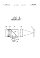
- FIG. 5 of the accompanying drawings schematically shows the optical system disclosed in U.S. Pat. No. 4,953,960.
- a light beam from a reticle 21 on which a pattern to be reduction-transferred is depicted is converted into a substantially parallel light beam by a lens unit 22 having positive refractive power and is applied to a prism type beam splitter (beam splitter cube) 23.
- the light beam transmitted through the joint surface 23a of this beam splitter 23 is diffused by a correction lens unit 24 having negative refractive power and is reflected by a concave reflecting mirror 25.
- the light beam reflected by the concave reflecting mirror 25 passes through the correction lens unit 24 again and is reflected by the joint surface 23a of the beam splitter 23, whereafter it is converged on a wafer 27 by a lens unit 26 having positive refractive power, and the reduced image of the reticle pattern is formed on the wafer 27.
- a half mirror comprising a plane parallel plate is used instead of the prism type beam splitter 23 is also disclosed.
- the reduction magnification of the entire system is 1/4 and the magnification in the concave reflecting mirror 25 is 0.287.
- the magnification of the concave reflecting mirror in the example of the construction using the obliquely disposed plane parallel plate having a half-transmitting surface is 0.136. That is, in the example of the prior art, the design is made such that with the burden of reduction magnification cast on the concave reflecting mirror, aberrations attributable to a concave reflecting mirror of small reduction magnification are corrected by the correction lens unit 24 and the lens unit 26.
- the present invention has as an object the provision of a reduction projection optical system of a construction in which a beam splitter is disposed in a catadioptric system and in which spherical aberration attributable to a concave reflecting mirror is small.
- the catadioptric reduction projection optical system is an optical system for reduction-projecting the pattern of a first surface (1) onto a second surface (5), as shown, for example, in FIG. 1 of the accompanying drawings, and has a first lens unit G1 preferably having reduction magnification and widening a light beam from the first surface, a prism type beam splitter (2) transmitting therethrough or reflecting the light beam from the first lens unit, a concave reflecting mirror (4) returning the light beam emerging from the beam splitter to the beam splitter while converging the light beam, and a second lens unit G2 having positive refractive power and converging the light beam returned to the beam splitter and reflected by or transmitted through the beam splitter, and forming the reduced image of the pattern of the first surface (1) on the second surface (5).
- a first lens unit G1 preferably having reduction magnification and widening a light beam from the first surface
- a prism type beam splitter (2) transmitting therethrough or reflecting the light beam from the first lens unit
- the radius of curvature of the concave reflecting mirror (4) be set to a range seventeen times to twenty-five times as great as the diameter of the exposure area (image circle) on the second surface (5).
- magnification of the concave reflecting mirror (4) be 0.6 time to 1.1 times.
- the inclination of the off-axis principal ray incident on the concave reflecting mirror (4) with respect to the optical axis be 5 degrees or less.
- the image of the pattern of the first surface reduced by the first lens unit having reduction magnification is located near the conjugate point of the center of curvature of the concave reflecting mirror and therefore, the concave reflecting mirror can be used at substantially one-to-one magnification.
- magnification of the concave reflecting mirror is 0.6 time to 1.1 times, a predetermined reduction magnification is obtained as a whole, and then the spherical aberration by the concave reflecting mirror can be corrected best.
- FIG. 1 is a cross-sectional view showing the basic construction of an embodiment of a catadioptric reduction projection optical system according to the present invention.
- FIG. 2 is a lens construction view showing the specific construction of the optical system of FIG. 1.
- FIGS. 3A, 3B, 3C and 3D show the longitudinal aberrations of the embodiment of FIG. 2.
- FIGS. 4A, 4B, 4C and 4D show the lateral aberrations of the embodiment of FIG. 2.
- FIG. 5 is a cross-sectional view showing the basic construction of a catadioptric reduction projection optical system according to the prior art.
- an on-axis light beam is used to expose a wide area collectively.
- the concave reflecting mirror (4) is endowed with most of the refractive power of the entire system to suppress the creation of chromatic aberration.
- the light beam incident on the concave reflecting mirror (4) can become substantially perpendicular to the reflecting surface thereof. This means that the concave reflecting mirror (4) can be used substantially as one-to-one magnification imaging.
- the simplest construction for that is a construction in which the first surface (1) is located near the center of curvature of the reflecting surface of the concave reflecting mirror (4) (actually the conjugate point thereof by the beam splitter (2)).
- the first surface (1) becomes too close to the concave reflecting mirror (4), the maximum value of the inclination of the off-axis principal ray with respect to the optical axis will become great and astigmatism, etc. will become great.
- the angle of incidence of the light beam onto the prism type beam splitter (2) becomes great, the loss of the quantity of light will become great and flare and imaging performance will be deteriorated and thus, good imaging will not be accomplished.
- the light beam from the first surface (1) is widened by the first lens unit G1 preferably having reduction magnification, whereby the reduced image of the pattern on the first surface (1) is disposed near the conjugate point of the center of curvature of the concave reflecting mirror (4). Since the whole of the optical system must be made into a reduction system, the reduction of the image by the first lens unit G1 is useful. Further, the image is reduced also by the second lens unit G2 having positive refractive power which is disposed between the beam splitter (2) and the second surface (5), whereby a desired reduction rate can be obtained as a whole, in spite of the concave reflecting mirror (4) being of substantially one-to-one magnification.
- the separation of the incident light and the reflected light from each other is effected by the prism type beam splitter (2).
- the use of the prism type beam splitter is for preventing the creation of astigmatism and coma caused by the use of an obliquely disposed plane parallel plate having a half-transmitting surface.
- the angular characteristic of the beam splitter (2) it is preferable that for example, the number of layers of multilayer film used as translucent film be made as small as possible. More specifically, it is preferable that transmittance >50% >reflectance.
- a quarter wavelength plate (3) is disposed between the beam splitter (2) and the concave reflecting mirror (4), whereby reflection efficiency and transmission efficiency in the joint surface of the beam splitter (2) can be improved greatly. Accordingly, the effective utilization of the quantity of light and a reduction in flare can be achieved.
- the radius of curvature of the concave reflecting mirror (4) should preferably be seventeen times to twenty-five times as great as the diameter of the exposure area (image circle) on the second surface (5).
- a certain degree of reduction magnification can be achieved by the converging function thereof and influence is imparted to Petzval sum, astigmatism and distortion and thus, it becomes possible to maintain the aberration balance with the refracting system comprising the first lens unit G1 and the second lens unit G2 good.
- the reason is that if the radius of curvature of the concave reflecting mirror becomes small and the refractive power thereof becomes great, the reduction magnification of the first lens unit G1 also becomes great in order that the light beam passing through the beam splitter (2) before and after the reflection on the concave reflecting mirror (4) may be made substantially perpendicular to the reflecting surface of the concave reflecting mirror and therefore, it is necessary that the refractive power of the positive refractive power of the second lens unit G2 be made great for the correction of spherical aberration.
- the second lens unit G2 is disposed near the second surface (5) as the image plane and therefore, for the correction of aberrations, refractive power greater than the refractive power of the first lens unit G1 is required of the second lens unit and thus, Petzval sum increases remarkably. Accordingly, to correct aberrations better, it is desirable that the radius of curvature of the concave reflecting mirror (4) be greater than nineteen times the diameter of the image circle of the reduced image.
- the concave reflecting mirror (4) is used at substantially one-to-one magnification, and it is preferable that the range of the magnification thereof be 0.6 time to 1.1 times. That is, if the magnification is smaller than 0.6 time, spherical aberration will become great and the optical system for correcting it will become complicated.
- the magnification of the entire system is a reduction magnification
- the inclination of the off-axis principal ray incident on the concave reflecting mirror (4) with respect to the optical axis be 5 degrees or less.
- the inclination of the off-axis principal ray incident on the concave reflecting mirror (4) is equal to the inclination of the off-axis principal ray incident on the beam splitter (2) with respect to the optical axis.
- FIGS. 1 to FIGS. 4A, 4B, 4C and 4D A specific embodiment of the catadioptric reduction projection optical system according to the present invention will hereinafter be described with reference to FIGS. 1 to FIGS. 4A, 4B, 4C and 4D.
- This embodiment is one in which the present invention is applied to the optical system of an exposure apparatus for the manufacture of semiconductors in which the wavelength use is 948 nm and the reduction magnification is 1/5.
- the reference numeral 1 designates a reticle on which a pattern for an integrated circuit is formed.
- a first lens unit G1 having reduction magnification, a prism type beam splitter 2, a quarter wavelength plate 3 and a concave reflecting mirror 4 are successively disposed along the optical axis perpendicular to the reticle 1, and a second lens unit G2 having positive refractive power and a wafer 5 are successively disposed in a direction in which the reflected light by the concave reflecting mirror 4 is reflected by the joint surface 2a of the beam splitter 2.
- the reticle 1 is illuminated by an illuminating optical system, not shown, and a light beam emerging from the reticle 1 is caused to diverge by the first lens unit G1 of having reduction magnification and enter the beam splitter 2, and the light beam transmitted through the joint surface 2a of this beam splitter 2 is caused to be incident on the concave reflecting mirror 4 through the quarter wavelength plate 3.
- the radius of curvature of the concave reflecting mirror 4 is about 400 mm.
- the light beam reflected by the concave reflecting mirror 4 passes through the quarter wavelength plate 3 while converging and again enters the beam splitter 2, and the light beam reflected by the joint surface 2a of this beam splitter 2 is condensed on the wafer 5 by the second lens unit G2. Thereby the reduced image of the pattern on the reticle 1 is formed on the wafer 5.
- a light beam polarized in parallelism to the plane of the drawing sheet of FIG. 1 (P-polarized light) is used as illuminating light.
- P-polarized light a light beam polarized in parallelism to the plane of the drawing sheet of FIG. 1
- most light is transmitted through the joint surface 2a due to the polarization characteristic of the beam splitter 2, and this transmitted light is further transmitted through the quarter wavelength plate 3, whereby it becomes circularly polarized light.
- the beam of this circularly polarized light is reflected by the concave reflecting mirror 4 and becomes circularly polarized light opposite in direction, but when the beam of this circularly polarized light opposite in direction is again transmitted through the quarter wavelength plate 3, it becomes linearly polarized light perpendicular to the plane of the drawing sheet of FIG. 1.
- single-axis crystal for example, rock crystal
- the quarter wavelength plate 3 it is desirable that single-axis crystal (for example, rock crystal) of a small thickness be used as the quarter wavelength plate 3.
- This astigmatism cannot be corrected by a method of cementing two crystals together by rotating the optical axes thereof by 90° relative to each other as is usually done for a wavelength plate. That is, astigmatism will occur for both of normal rays and abnormal rays.
- wave surface aberration W Assuming that the amount of this astigmatism is represented by wave surface aberration W, the wave surface aberration is expressed by the following equation:
- (n o -n e ) is the difference between the refractive indices of normal rays and abnormal rays
- d is the thickness of the crystal
- ⁇ is the deviation from the parallel light beam, i.e., the angle of divergence (or convergence) of the light beam.
- the quarter wavelength plate 3 is very thin like this and therefore, it may be adhesively secured to and supported by the beam splitter 2.
- the design is made such that the light beam transmitted through the beam splitter 2 is directed to the concave reflecting mirror 4 and the light beam reflected from this concave reflecting mirror 4 and further reflected by the beam splitter 2 is converged by the second lens unit G2.
- the concave reflecting mirror 4 may be disposed so as to sandwich the beam splitter 2 between it and the second lens unit G2, and the light beam reflected by the beam splitter 2 may be applied to the concave reflecting mirror 4, and the light beam reflected from this concave reflecting mirror 4 and transmitted through the beam splitter 2 may be converged by the second lens unit G2.
- a polarizing beam splitter is used as the beam splitter 2
- reflectance and transmittance can be further improved by the combination thereof with the quarter wavelength plate.
- the beam splitter 2 is not a polarizing beam splitter but an ordinary beam splitter, it has some degree of polarizing characteristic and therefore, reflectance and transmittance can be improved by the combination thereof with the quarter wavelength plate.
- FIG. 2 shows a specific lens construction view of such optical system.
- the first lens unit G1 comprises, in succession from the reticle 1 side, a negative meniscus lens L 11 having its convex surface facing the reticle 1, a biconvex lens L 12 , a biconvex lens L 13 , a negative meniscus lens L 14 having its convex surface facing the reticle 1, and a biconcave lens L 15 .
- the second lens unit G2 comprises, in succession from the prism type beam splitter 2 side, a biconvex lens L 21 , a biconcave lens L 22 , a biconvex lens L 23 , a negative meniscus lens L 24 having its convex surface facing the beam splitter 2, and a positive meniscus lens L 25 having its convex surface facing the beam splitter 2.
- the quarter wavelength plate 3 in FIG. 1 is not shown in FIG. 2 because its thickness is negligibly small.
- the ith surface As regards the sign of the radius of curvature r i of the ith surface, between the reticle 1 and the concave reflecting mirror 4, a case where the ith surface is convex relative to the reticle 1 is chosen to positive, and between the joint surface of the beam splitter and the wafer, a case where the ith surface is convex relative to the joint surface is chosen to positive.
- the sign of the surface spacing d i between the ith surface and the (i+1)th surface is chosen to negative in the area wherein the reflected light from the concave reflecting mirror 4 passes to the joint surface of the beam splitter 2, and is chosen to positive in the other areas.
- the radius of curvature r i , the surface spacing d i and the glass materials of FIG. 2 will be shown in Table 1 below.
- CaF 2 represents fluorite
- SiO 2 represents quartz glass.
- the refractive indices of quartz glass and fluorite for the standard wavelength used (248 nm) are as follows:
- quartz glass 1.50855
- the reduction magnification is 1/5
- the numerical aperture is 0.45
- the diameter d of the effective exposure area (image circle) on the wafer 5 is 20 mm.
- the radius of curvature r of the concave reflecting mirror 4 is 394,591 mm, and the radius of curvature r is about 19.7 times as great as the diameter d.
- the magnification ⁇ in the concave reflecting mirror 4 is about 0.707 and is within said range, and can be regarded as substantially one-to-one magnification.
- the maximum value of the inclination of the marginal ray (Rand ray) from the on-axis object point incident on the concave reflecting mirror 4 with respect to the optical axis is 7.72°
- the maximum value of the inclination of the off-axis principal ray incident on the concave reflecting mirror 4 with respect to the optical axis is 3.23°
- the maximum value of the inclination of the Rand ray emerging from the concave reflecting mirror 4 with respect to the optical axis is 10.76°.
- FIGS. 3A-3D Longitudinal aberration graphs of the embodiment of FIG. 2 are shown in FIGS. 3A-3D, and lateral aberration graphs of the same embodiment are shown in FIGS. 4A-4D.
- curves J, P and Q show that the wavelengths used are 248.4 nm, 247.9 nm and 248.9 nm, respectively. From these aberration graphs, it is seen that in the present embodiment, in spite of the numerical, aperture being great, aberrations including chromatic aberration are corrected well in the area of a Wide image circle of a radius 10.6 mm.
- the concave reflecting mirror 4 in the above-described embodiment is used at substantially one-to-one magnification and therefore, light reflected by the concave reflecting mirror 4 tends to return. Accordingly, ghost (i.e., flare) which is the inverted image of the original image is liable to be created on the surfaces of the reticle 1 and the wafer 5. This is reduced by the quarter wavelength plate 3, but the reduction may be insufficient when limitations to flare are severe. However, when limitations to flare are severe, it can be coped with by covering one side of the reticle 1 or one side of the wafer 5 to thereby eliminate ghost. This method is suited for a slit scan type exposure apparatus.
Abstract
A catadioptric reduction projection optical system having a first lens unit having negative refractive power and widening a light beam from a reticle, a prism type beam splitter for transmitting therethrough a light beam from the first lens unit, a concave reflecting mirror for returning the light beam emerging from the beam splitter to the beam splitter while converging it, and a second lens unit having positive refractive power and converging the light beam returned to the beam splitter and reflected by the beam splitter, and forming the reduced image of a pattern on the reticle on a wafer.
Description
This is a division of application Ser. No. 08/482,505 filed Jun. 7, 1995, which is a continuation of application Ser. No. 08/062,725 filed May 18, 1993 (abandoned), which is a continuation of application Ser. No. 07/948,248 filed Sep. 21, 1992 (abandoned).
1. Field of the Invention
This invention relates to a catadioptric reduction projection optical system for use, for example, in an exposure apparatus for the manufacture of semiconductive elements, and particularly suitable for application to an optical system for reduction-projecting a pattern more enlarged than the pattern of a real element.
2. Related Background Art
Semiconductive integrated circuits have become more and more minute and exposure apparatuses for printing the patterns thereof are required to have higher resolving power. To satisfy this requirement, the wavelength of a light source must be made short and the numerical aperture (N.A.) of an optical system must be made great. However, if the wavelength becomes short, glass materials standing practical use will become limited because of the absorption of light. If the wavelength becomes 300 mm or shorter, what can be practically used will be only synthetic quartz and fluorite (calcium fluoride). Also, fluorite is bad in temperature characteristic and cannot be used in a great quantity. Therefore, it is very difficult to make a projection lens of a refracting system alone. Further, because of the difficulty of aberration correction, it is also difficult to make a projection optical system having a great numerical aperture of a reflecting system alone.
So, there have been proposed various techniques of constructing a projection optical system by combining a reflecting system and a refracting system. An example of such techniques is a ring field optical system as disclosed in U.S. Pat. No. 4,747,678. In this optical system, an off-axis light beam is used so that incident light and reflected light may not interfere with each other, and the design is made such that only an off-axis zonal portion is exposed to light.
As another example, a projection exposure apparatus comprising a projection optical system having a beam splitter disposed therein, and a catadioptric system for collectively projecting the image of a reticle (mask) by an on-axis light beam is disclosed, for example, in U.S. Pat. Nos. 3,698,808 and 4,953,960.
FIG. 5 of the accompanying drawings schematically shows the optical system disclosed in U.S. Pat. No. 4,953,960. In FIG. 5, a light beam from a reticle 21 on which a pattern to be reduction-transferred is depicted is converted into a substantially parallel light beam by a lens unit 22 having positive refractive power and is applied to a prism type beam splitter (beam splitter cube) 23. The light beam transmitted through the joint surface 23a of this beam splitter 23 is diffused by a correction lens unit 24 having negative refractive power and is reflected by a concave reflecting mirror 25. The light beam reflected by the concave reflecting mirror 25 passes through the correction lens unit 24 again and is reflected by the joint surface 23a of the beam splitter 23, whereafter it is converged on a wafer 27 by a lens unit 26 having positive refractive power, and the reduced image of the reticle pattern is formed on the wafer 27. An example in which a half mirror comprising a plane parallel plate is used instead of the prism type beam splitter 23 is also disclosed.
In the example of the prior art shown in FIG. 5, the reduction magnification of the entire system is 1/4 and the magnification in the concave reflecting mirror 25 is 0.287. Also, the magnification of the concave reflecting mirror in the example of the construction using the obliquely disposed plane parallel plate having a half-transmitting surface is 0.136. That is, in the example of the prior art, the design is made such that with the burden of reduction magnification cast on the concave reflecting mirror, aberrations attributable to a concave reflecting mirror of small reduction magnification are corrected by the correction lens unit 24 and the lens unit 26.
In the ring field optical system according to the prior art, however, it is difficult to make the numerical aperture great. Moreover, it is also impossible to expose collectively and therefore, it is necessary to effect exposure while moving the reticle and the wafer at different speeds correspondingly to the reduction ratio of the optical system, and this has led to the inconvenience that the construction of the mechanical system becomes complex.
Also, in the construction disclosed in U.S. Pat. No. 3,698,808, there is the inconvenience that the flare by the reflection on the refracting surface of the optical system subsequent to the beam splitter is great. Further, characteristics such as the reflectance irregularity, absorption and phase change of the beam splitter are not at all taken into account and therefore, the resolving power is low and the magnification of the entire system is one-to-one magnification, and the apparatus of the prior art cannot possibly stand the use as a semiconductor manufacturing exposure apparatus of the coming generation of which higher resolving power is required.
Furthermore, in the projection optical system disclosed in U.S. Pat. No. 4,953,960, almost all of the reduction magnification of the entire system is borne by the concave reflecting mirror, and this leads to the inconvenience that spherical aberration created by the concave reflecting mirror is great. Accordingly, an optical system for correcting that spherical aberration becomes complicated. Also, since the design is made such that the light beam from the reticle 21 is converted into a substantially parallel light beam by the lens unit 22 of positive refractive power, the spacing between the reticle 21 and the beam splitter 23 becomes long, and this leads to the bulkiness of the optical system.
In view of the above-noted points, the present invention has as an object the provision of a reduction projection optical system of a construction in which a beam splitter is disposed in a catadioptric system and in which spherical aberration attributable to a concave reflecting mirror is small.
The catadioptric reduction projection optical system according to the present invention is an optical system for reduction-projecting the pattern of a first surface (1) onto a second surface (5), as shown, for example, in FIG. 1 of the accompanying drawings, and has a first lens unit G1 preferably having reduction magnification and widening a light beam from the first surface, a prism type beam splitter (2) transmitting therethrough or reflecting the light beam from the first lens unit, a concave reflecting mirror (4) returning the light beam emerging from the beam splitter to the beam splitter while converging the light beam, and a second lens unit G2 having positive refractive power and converging the light beam returned to the beam splitter and reflected by or transmitted through the beam splitter, and forming the reduced image of the pattern of the first surface (1) on the second surface (5).
In this case, it is preferable that the radius of curvature of the concave reflecting mirror (4) be set to a range seventeen times to twenty-five times as great as the diameter of the exposure area (image circle) on the second surface (5).
Also, it is preferable that the magnification of the concave reflecting mirror (4) be 0.6 time to 1.1 times.
In addition, it is preferable that the inclination of the off-axis principal ray incident on the concave reflecting mirror (4) with respect to the optical axis be 5 degrees or less.
According to the present invention, the image of the pattern of the first surface reduced by the first lens unit having reduction magnification is located near the conjugate point of the center of curvature of the concave reflecting mirror and therefore, the concave reflecting mirror can be used at substantially one-to-one magnification. This leads to the advantage that spherical aberration attributable to the concave reflecting mirror can be decreased and as a whole, aberrations can be corrected well.
Also, there is the advantage that when the radius of curvature of the concave reflecting mirror is seventeen times to twenty-five times as great as the diameter of the exposure area of the second surface, astigmatism and distortion can be corrected easily and a predetermined reduction magnification can be obtained easily.
Further, when the magnification of the concave reflecting mirror is 0.6 time to 1.1 times, a predetermined reduction magnification is obtained as a whole, and then the spherical aberration by the concave reflecting mirror can be corrected best.
Furthermore, there is the advantage that when the inclination of the off-axis principal ray incident on the concave reflecting mirror with respect to the optical axis is limited to 5° or less, the amount of aberration such as astigmatism can be suppressed within a predetermined range and the irregularity of the reflectance and transmittance in the beam splitter can be suppressed.
FIG. 1 is a cross-sectional view showing the basic construction of an embodiment of a catadioptric reduction projection optical system according to the present invention.
FIG. 2 is a lens construction view showing the specific construction of the optical system of FIG. 1.
FIGS. 3A, 3B, 3C and 3D show the longitudinal aberrations of the embodiment of FIG. 2.
FIGS. 4A, 4B, 4C and 4D show the lateral aberrations of the embodiment of FIG. 2.
FIG. 5 is a cross-sectional view showing the basic construction of a catadioptric reduction projection optical system according to the prior art.
According to the present invention, in a construction comprising a combination of a reflecting system and a refracting system, an on-axis light beam is used to expose a wide area collectively. Also, since there is no chromatic aberration in the reflecting system, the concave reflecting mirror (4) is endowed with most of the refractive power of the entire system to suppress the creation of chromatic aberration. Also, for the suppression of spherical aberration in a concave reflecting mirror (4) which is the main purpose of the present invention, the light beam incident on the concave reflecting mirror (4) can become substantially perpendicular to the reflecting surface thereof. This means that the concave reflecting mirror (4) can be used substantially as one-to-one magnification imaging.
The simplest construction for that is a construction in which the first surface (1) is located near the center of curvature of the reflecting surface of the concave reflecting mirror (4) (actually the conjugate point thereof by the beam splitter (2)). However, if the first surface (1) becomes too close to the concave reflecting mirror (4), the maximum value of the inclination of the off-axis principal ray with respect to the optical axis will become great and astigmatism, etc. will become great. Further, if the angle of incidence of the light beam onto the prism type beam splitter (2) becomes great, the loss of the quantity of light will become great and flare and imaging performance will be deteriorated and thus, good imaging will not be accomplished.
So, in the present invention, the light beam from the first surface (1) is widened by the first lens unit G1 preferably having reduction magnification, whereby the reduced image of the pattern on the first surface (1) is disposed near the conjugate point of the center of curvature of the concave reflecting mirror (4). Since the whole of the optical system must be made into a reduction system, the reduction of the image by the first lens unit G1 is useful. Further, the image is reduced also by the second lens unit G2 having positive refractive power which is disposed between the beam splitter (2) and the second surface (5), whereby a desired reduction rate can be obtained as a whole, in spite of the concave reflecting mirror (4) being of substantially one-to-one magnification.
Also, the separation of the incident light and the reflected light from each other is effected by the prism type beam splitter (2). The use of the prism type beam splitter is for preventing the creation of astigmatism and coma caused by the use of an obliquely disposed plane parallel plate having a half-transmitting surface. Further, to make the angular characteristic of the beam splitter (2) good, it is preferable that for example, the number of layers of multilayer film used as translucent film be made as small as possible. More specifically, it is preferable that transmittance >50% >reflectance. Further, where use is made of multilayer film which has a considerably strong polarizing characteristic, a quarter wavelength plate (3) is disposed between the beam splitter (2) and the concave reflecting mirror (4), whereby reflection efficiency and transmission efficiency in the joint surface of the beam splitter (2) can be improved greatly. Accordingly, the effective utilization of the quantity of light and a reduction in flare can be achieved.
A description will now be given of the reason why the radius of curvature of the concave reflecting mirror (4) should preferably be seventeen times to twenty-five times as great as the diameter of the exposure area (image circle) on the second surface (5). In a concave reflecting mirror, a certain degree of reduction magnification can be achieved by the converging function thereof and influence is imparted to Petzval sum, astigmatism and distortion and thus, it becomes possible to maintain the aberration balance with the refracting system comprising the first lens unit G1 and the second lens unit G2 good. That is, if the radius of curvature of the concave reflecting mirror (4) is below seventeen times the diameter of the image circle of the second surface (5), it will be advantageous for the correction of chromatic aberration, but Petzval sum will increase in the positive direction and astigmatism and distortion will also increase.
The reason is that if the radius of curvature of the concave reflecting mirror becomes small and the refractive power thereof becomes great, the reduction magnification of the first lens unit G1 also becomes great in order that the light beam passing through the beam splitter (2) before and after the reflection on the concave reflecting mirror (4) may be made substantially perpendicular to the reflecting surface of the concave reflecting mirror and therefore, it is necessary that the refractive power of the positive refractive power of the second lens unit G2 be made great for the correction of spherical aberration. However, the second lens unit G2 is disposed near the second surface (5) as the image plane and therefore, for the correction of aberrations, refractive power greater than the refractive power of the first lens unit G1 is required of the second lens unit and thus, Petzval sum increases remarkably. Accordingly, to correct aberrations better, it is desirable that the radius of curvature of the concave reflecting mirror (4) be greater than nineteen times the diameter of the image circle of the reduced image.
If conversely, the radius of curvature of the concave reflecting mirror (4) becomes great beyond twenty-five times the diameter of the image circle of the reduced image, it will be advantageous for the correction of astigmatism and distortion, but it will become difficult to obtain a desired reduction magnification and the correction of chromatic aberration will become insufficient, and this is not very practical.
In the present invention, the concave reflecting mirror (4) is used at substantially one-to-one magnification, and it is preferable that the range of the magnification thereof be 0.6 time to 1.1 times. That is, if the magnification is smaller than 0.6 time, spherical aberration will become great and the optical system for correcting it will become complicated. On the other hand, now that the magnification of the entire system is a reduction magnification, it is originally not preferable that the magnification of the concave reflecting mirror (4) exceed 1 time, but the fact that the magnification becomes great means that the radius of curvature becomes great and further that spherical aberration can be made small. So, it is considered that when importance is attached to an improvement in aberrations even at the sacrifice of magnification, up to the order of 1.1 times, can be allowed as the magnification of the concave reflecting mirror (4).
A description will now be given of the reason why it is preferable that the inclination of the off-axis principal ray incident on the concave reflecting mirror (4) with respect to the optical axis be 5 degrees or less. First, unless the inclination of the off-axis principal ray is limited like this, astigmatism, etc. on the concave reflecting mirror (4) will become too great. Further, the inclination of the off-axis principal ray incident on the concave reflecting mirror (4) is equal to the inclination of the off-axis principal ray incident on the beam splitter (2) with respect to the optical axis. If the inclination of the off-axis principal ray with respect to the beam splitter (2) is limited like that, the irregularity of reflectance and transmittance on the joint surface of the beam splitter (2) will become small and the irregularity of the variation in phase will also become small and therefore, the imaging performance will be improved as a whole.
A specific embodiment of the catadioptric reduction projection optical system according to the present invention will hereinafter be described with reference to FIGS. 1 to FIGS. 4A, 4B, 4C and 4D. This embodiment is one in which the present invention is applied to the optical system of an exposure apparatus for the manufacture of semiconductors in which the wavelength use is 948 nm and the reduction magnification is 1/5.
Referring to FIG. 1 which schematically shows the construction of the optical system of the present embodiment, the reference numeral 1 designates a reticle on which a pattern for an integrated circuit is formed. A first lens unit G1 having reduction magnification, a prism type beam splitter 2, a quarter wavelength plate 3 and a concave reflecting mirror 4 are successively disposed along the optical axis perpendicular to the reticle 1, and a second lens unit G2 having positive refractive power and a wafer 5 are successively disposed in a direction in which the reflected light by the concave reflecting mirror 4 is reflected by the joint surface 2a of the beam splitter 2.
The reticle 1 is illuminated by an illuminating optical system, not shown, and a light beam emerging from the reticle 1 is caused to diverge by the first lens unit G1 of having reduction magnification and enter the beam splitter 2, and the light beam transmitted through the joint surface 2a of this beam splitter 2 is caused to be incident on the concave reflecting mirror 4 through the quarter wavelength plate 3. The radius of curvature of the concave reflecting mirror 4 is about 400 mm. The light beam reflected by the concave reflecting mirror 4 passes through the quarter wavelength plate 3 while converging and again enters the beam splitter 2, and the light beam reflected by the joint surface 2a of this beam splitter 2 is condensed on the wafer 5 by the second lens unit G2. Thereby the reduced image of the pattern on the reticle 1 is formed on the wafer 5.
Also, a light beam polarized in parallelism to the plane of the drawing sheet of FIG. 1 (P-polarized light) is used as illuminating light. In this case, most light is transmitted through the joint surface 2a due to the polarization characteristic of the beam splitter 2, and this transmitted light is further transmitted through the quarter wavelength plate 3, whereby it becomes circularly polarized light. The beam of this circularly polarized light is reflected by the concave reflecting mirror 4 and becomes circularly polarized light opposite in direction, but when the beam of this circularly polarized light opposite in direction is again transmitted through the quarter wavelength plate 3, it becomes linearly polarized light perpendicular to the plane of the drawing sheet of FIG. 1. Most of the light beam polarized in a direction perpendicular to the plane of the drawing sheet of FIG. 1 by the polarization characteristic of the beam splitter 2 is reflected by the joint surface 2a and travels toward the wafer 5. Thereby, the return light to the reticle 1 is decreased and thus, the effective utilization of the light beam and a decrease in flare are achieved.
Further, it is desirable that single-axis crystal (for example, rock crystal) of a small thickness be used as the quarter wavelength plate 3. The reason is that if the light beam transmitted through the quarter wavelength plate deviates from a parallel light beam, astigmatism will occur for abnormal rays. This astigmatism cannot be corrected by a method of cementing two crystals together by rotating the optical axes thereof by 90° relative to each other as is usually done for a wavelength plate. That is, astigmatism will occur for both of normal rays and abnormal rays.
Assuming that the amount of this astigmatism is represented by wave surface aberration W, the wave surface aberration is expressed by the following equation:
W=(n.sub.o -n.sub.e)dθ.sup.2 /2,
where (no -ne) is the difference between the refractive indices of normal rays and abnormal rays, d is the thickness of the crystal, and θ is the deviation from the parallel light beam, i.e., the angle of divergence (or convergence) of the light beam.
For example, where the quarter wavelength plate is constructed by rock crystal, (no -ne)=0.01 and the divergent (convergent) state of the light beam is θ=14°. When the wavelength used is λ, to maintain a sufficiently good imaging performance, it is necessary to maintain the wave surface aberration W less than a quarter wavelength, i.e., λ/4. For that purpose, on the assumption that the wavelength λ is 248 nm, from the foregoing equation, d must be
d<100 μm.
The quarter wavelength plate 3 is very thin like this and therefore, it may be adhesively secured to and supported by the beam splitter 2.
In the construction of FIG. 1, the design is made such that the light beam transmitted through the beam splitter 2 is directed to the concave reflecting mirror 4 and the light beam reflected from this concave reflecting mirror 4 and further reflected by the beam splitter 2 is converged by the second lens unit G2. However, the concave reflecting mirror 4 may be disposed so as to sandwich the beam splitter 2 between it and the second lens unit G2, and the light beam reflected by the beam splitter 2 may be applied to the concave reflecting mirror 4, and the light beam reflected from this concave reflecting mirror 4 and transmitted through the beam splitter 2 may be converged by the second lens unit G2. Also, if a polarizing beam splitter is used as the beam splitter 2, reflectance and transmittance can be further improved by the combination thereof with the quarter wavelength plate. However, even if the beam splitter 2 is not a polarizing beam splitter but an ordinary beam splitter, it has some degree of polarizing characteristic and therefore, reflectance and transmittance can be improved by the combination thereof with the quarter wavelength plate.
A specific example of the construction of the optical system of FIG. 1 will hereinafter be described.
FIG. 2 shows a specific lens construction view of such optical system. As shown in FIG. 2, the first lens unit G1 comprises, in succession from the reticle 1 side, a negative meniscus lens L11 having its convex surface facing the reticle 1, a biconvex lens L12, a biconvex lens L13, a negative meniscus lens L14 having its convex surface facing the reticle 1, and a biconcave lens L15. The second lens unit G2 comprises, in succession from the prism type beam splitter 2 side, a biconvex lens L21, a biconcave lens L22, a biconvex lens L23, a negative meniscus lens L24 having its convex surface facing the beam splitter 2, and a positive meniscus lens L25 having its convex surface facing the beam splitter 2. The quarter wavelength plate 3 in FIG. 1 is not shown in FIG. 2 because its thickness is negligibly small.
In order to represent the shapes of and the spacings between the lenses of FIG. 2, with the reticle 1 as the first surface, the surfaces through which the light emerging from the reticle 1 passes until it arrives at the wafer 5 are called the ith surface (i=2, 3, . . . 27). As regards the sign of the radius of curvature ri of the ith surface, between the reticle 1 and the concave reflecting mirror 4, a case where the ith surface is convex relative to the reticle 1 is chosen to positive, and between the joint surface of the beam splitter and the wafer, a case where the ith surface is convex relative to the joint surface is chosen to positive. Also, the sign of the surface spacing di between the ith surface and the (i+1)th surface is chosen to negative in the area wherein the reflected light from the concave reflecting mirror 4 passes to the joint surface of the beam splitter 2, and is chosen to positive in the other areas. The radius of curvature ri, the surface spacing di and the glass materials of FIG. 2 will be shown in Table 1 below. In the column of glass materials CaF2 represents fluorite and SiO2 represents quartz glass. The refractive indices of quartz glass and fluorite for the standard wavelength used (248 nm) are as follows:
quartz glass: 1.50855
fluorite: 1.46799
              TABLE 1
______________________________________
                               glass
i      ri              di      material
______________________________________
 1     ∞         161.900
 2     473.382         23.000  CaF.sub.2
 3     171.144         6.000
 4     172.453         29.000  SiO.sub.2
 5     -246.006        16.818
 6     148.803         20.000  SiO.sub.2
 7     -2656.033       1.000
 8     230.632         16.000  CaF.sub.2
 9     102.960         30.000
10     -143.364        18.000  SiO.sub.2
11     147.730         223.179
12     ∞         145.000 SiO.sub.2
13     ∞         20.000
14     -394.591        -20.000
15     ∞         -72.500 SiO.sub.2
16     ∞         72.500  SiO.sub.2
17     ∞         42.626
18     81.489          17.000  CaF.sub.2
19     -1339.728       7.000
20     -172.194        11.000  SiO.sub.2
21     204.909         4.300
22     461.579         23.800  CaF.sub.2
23     -142.095        0.200
24     55.322          18.273  SiO.sub.2
25     40.925          3.000
26     53.590          11.000  CaF.sub.2
27     849.726         17.541
______________________________________
In the embodiment of FIG. 2, the reduction magnification is 1/5, the numerical aperture is 0.45, and the diameter d of the effective exposure area (image circle) on the wafer 5 is 20 mm. The radius of curvature r of the concave reflecting mirror 4 is 394,591 mm, and the radius of curvature r is about 19.7 times as great as the diameter d. Also, the magnification β in the concave reflecting mirror 4 is about 0.707 and is within said range, and can be regarded as substantially one-to-one magnification.
Further, the maximum value of the inclination of the marginal ray (Rand ray) from the on-axis object point incident on the concave reflecting mirror 4 with respect to the optical axis is 7.72°, and the maximum value of the inclination of the off-axis principal ray incident on the concave reflecting mirror 4 with respect to the optical axis is 3.23°. Incidentally, the maximum value of the inclination of the Rand ray emerging from the concave reflecting mirror 4 with respect to the optical axis is 10.76°.
Longitudinal aberration graphs of the embodiment of FIG. 2 are shown in FIGS. 3A-3D, and lateral aberration graphs of the same embodiment are shown in FIGS. 4A-4D. In these aberration graphs, curves J, P and Q show that the wavelengths used are 248.4 nm, 247.9 nm and 248.9 nm, respectively. From these aberration graphs, it is seen that in the present embodiment, in spite of the numerical, aperture being great, aberrations including chromatic aberration are corrected well in the area of a Wide image circle of a radius 10.6 mm.
Finally, flare will be described for information. The concave reflecting mirror 4 in the above-described embodiment is used at substantially one-to-one magnification and therefore, light reflected by the concave reflecting mirror 4 tends to return. Accordingly, ghost (i.e., flare) which is the inverted image of the original image is liable to be created on the surfaces of the reticle 1 and the wafer 5. This is reduced by the quarter wavelength plate 3, but the reduction may be insufficient when limitations to flare are severe. However, when limitations to flare are severe, it can be coped with by covering one side of the reticle 1 or one side of the wafer 5 to thereby eliminate ghost. This method is suited for a slit scan type exposure apparatus.
Of course, the present invention is not restricted to the above-described embodiment, but can adopt various constructions without departing from the gist of the invention.
Claims (19)
1. A catadioptric reduction projection optical system for projecting a reduced image of a pattern of a first surface onto an exposure area of a second surface, including:
a first lens unit;
a prism type beam splitter;
a concave reflecting mirror; and
a second lens unit having a positive refractive power;
wherein said catadioptric reduction optical system is so constructed that light from said first surface passes through said first lens unit and subsequently through said prism type beam splitter, and is reflected by said concave reflecting mirror and thereafter passes through said second lens unit;
said catadioptric reduction optical system has a diameter of said exposure area including 20 mm; and
said concave reflecting mirror has magnification which is 0.6 times to 1.1 times.
2. The system of claim 1, wherein said first lens unit has reduction magnification.
3. The system of claim 1, wherein a radius of curvature of said concave reflecting mirror is seventeen times to twenty-five times as great as the diameter of the exposure area on said second surface.
4. The system of claim 1, wherein an inclination of an off-axis principal ray incident on said concave reflecting mirror with respect to an optical axis is 5 degrees or less.
5. The system of claim 1, wherein the prism type beam splitter has, a polarizing beam splitter surface, and said system has a quarter wavelength plate disposed between said prism type beam splitter and said concave reflecting mirror.
6. An apparatus for projecting a reduced image of a pattern of a first surface onto an exposure area of a second surface, with a catadioptric optical system disposed on an optical path between said first surface and said second surface, comprising:
a first lens unit;
a prism type beam splitter;
a concave reflecting mirror; and
a second lens unit having a positive refractive power;
wherein said catadioptric optical system is so constructed that light from said first surface passes through said first lens unit and subsequently through aid prism type beam splitter, and is reflected by said concave reflecting mirror and thereafter passes through said second lens unit;
said catadioptric optical system has a diameter of said exposure area including 20 mm; and
said concave reflecting mirror has magnification which is 0.6 times to 1.1 times.
7. The apparatus of claim 6, wherein said first lens unit has reduction magnification.
8. The apparatus of claim 6, wherein a radius of curvature of said concave reflecting mirror is seventeen times to twenty-five times as great as the diameter of the exposure area on said second surface.
9. The apparatus of claim 6, wherein an inclination of an off-axis principal ray incident on said concave reflecting mirror with respect to an optical axis is 5 degrees or less.
10. The apparatus of claim 6, wherein the prism type beam splitter has a polarizing beam splitter surface, and said system has a quarter wavelength plate disposed between said prism type beam splitter and said concave reflecting mirror.
11. A slit-scan type exposure apparatus for projecting a reduced image of a pattern of a first surface onto an exposure area of a second surface, with a catadioptric optical system disposed on an optical path between said first surface and said second surface, comprising:
a first lens unit;
a prism type beam splitter;
a concave reflecting mirror; and
a second lens unit having a positive refractive power;
wherein said catadioptric optical system is so constructed that light from said first surface passes through said first lens unit and subsequently through said prism type beam splitter, and is reflected by said concave reflecting mirror and thereafter passes through said second lens unit;
said catadioptric optical system has a diameter of said exposure area including 20 mm; and
said concave reflecting mirror has magnification which is 0.6 times to 1.1 times.
12. The apparatus of claim 1, wherein said first lens unit has reduction magnification.
13. The apparatus of claim 1, wherein a radius of curvature of said concave reflecting mirror is seventeen times to twenty-five times as great as the diameter of the exposure area on said second surface.
14. The apparatus of claim 12, wherein an inclination of an off-axis principal ray incident on said concave reflecting mirror with respect to an optical axis is 5 degrees or less.
15. The apparatus of claim 12, wherein the prism type beam splitter has a polarizing beam splitter surface, and said system has a quarter wavelength plate disposed between said prism type beam splitter and said concave reflecting mirror.
16. A method, for effecting a projection exposure of a reduced image of a first surface onto an exposure area of a second surface, comprising:
passing light, which has passed through said first surface, through a first lens unit;
passing light, which has passed through said first lens unit, through a prism type beam splitter;
reflecting light, which has passed through the prism type beam splitter, with a concave mirror having magnification which is 0.6 times to 1.1 times, to return the reflected light to said beam splitter;
passing light, which has returned to the beam splitter, through the beam splitter; and passing light, which has returned to and passed through the beam splitter, through a second lens unit having a positive refractive power to reach said second surface;
wherein said exposure area on said second surface Bas a diameter including 20 mm.
17. The method of claim 16, wherein said light passed through said first surface is polarized light;
said prism type beam splitter has a polarizing beam splitter surface; and
a polarization direction of light propagating from the beam splitter toward said concave mirror and a polarization direction of light propagating from said concave mirror toward said beam splitter are different from each other.
18. The method of claim 17, wherein said light propagating from the beam splitter toward said concave mirror passes through a quarter wavelength plate; and
said light propagating from said concave mirror toward said beam splitter passes through said quarter wavelength plate.
19. The method of claim 16, wherein said first lens unit has reduction magnification.
Priority Applications (1)
| Application Number | Priority Date | Filing Date | Title |
|---|---|---|---|
| US08/670,660 US5712735A (en) | 1991-09-28 | 1996-06-26 | Catadioptric reduction projection optical system |
Applications Claiming Priority (6)
| Application Number | Priority Date | Filing Date | Title |
|---|---|---|---|
| JP27659291A JP3235077B2 (en) | 1991-09-28 | 1991-09-28 | Exposure apparatus, exposure method using the apparatus, and method for manufacturing semiconductor device using the apparatus |
| JP3-276592 | 1991-09-28 | ||
| US94824892A | 1992-09-21 | 1992-09-21 | |
| US6272593A | 1993-05-18 | 1993-05-18 | |
| US48250595A | 1995-06-07 | 1995-06-07 | |
| US08/670,660 US5712735A (en) | 1991-09-28 | 1996-06-26 | Catadioptric reduction projection optical system |
Related Parent Applications (1)
| Application Number | Title | Priority Date | Filing Date |
|---|---|---|---|
| US48250595A Division | 1991-09-28 | 1995-06-07 |
Publications (1)
| Publication Number | Publication Date |
|---|---|
| US5712735A true US5712735A (en) | 1998-01-27 |
Family
ID=17571598
Family Applications (5)
| Application Number | Title | Priority Date | Filing Date |
|---|---|---|---|
| US08/670,660 Expired - Fee Related US5712735A (en) | 1991-09-28 | 1996-06-26 | Catadioptric reduction projection optical system |
| US08/670,650 Expired - Fee Related US5844728A (en) | 1991-09-28 | 1996-06-26 | Catadioptric reduction projection optical system |
| US08/698,253 Expired - Fee Related US6118596A (en) | 1991-09-28 | 1996-08-14 | Catadioptric reduction projection optical system and method |
| US09/246,673 Expired - Lifetime US6108140A (en) | 1991-09-28 | 1999-02-08 | Catadioptric reduction projection optical system and method |
| US09/777,654 Abandoned US20010024330A1 (en) | 1991-09-28 | 2001-02-07 | Catadioptric reduction projection optical system |
Family Applications After (4)
| Application Number | Title | Priority Date | Filing Date |
|---|---|---|---|
| US08/670,650 Expired - Fee Related US5844728A (en) | 1991-09-28 | 1996-06-26 | Catadioptric reduction projection optical system |
| US08/698,253 Expired - Fee Related US6118596A (en) | 1991-09-28 | 1996-08-14 | Catadioptric reduction projection optical system and method |
| US09/246,673 Expired - Lifetime US6108140A (en) | 1991-09-28 | 1999-02-08 | Catadioptric reduction projection optical system and method |
| US09/777,654 Abandoned US20010024330A1 (en) | 1991-09-28 | 2001-02-07 | Catadioptric reduction projection optical system |
Country Status (2)
| Country | Link |
|---|---|
| US (5) | US5712735A (en) |
| JP (1) | JP3235077B2 (en) |
Cited By (8)
| Publication number | Priority date | Publication date | Assignee | Title |
|---|---|---|---|---|
| EP1102100A2 (en) * | 1999-11-12 | 2001-05-23 | Carl Zeiss | Catadioptric objective with beamsplitter |
| US6377338B1 (en) * | 1998-08-18 | 2002-04-23 | Nikon Corporation | Exposure apparatus and method |
| US6391503B2 (en) | 1997-09-19 | 2002-05-21 | Nikon Corporation | Scanning exposure methods |
| US6636349B2 (en) * | 1992-12-14 | 2003-10-21 | Canon Kabushiki Kaisha | Reflection and refraction optical system and projection exposure apparatus using the same |
| US20060077566A1 (en) * | 2004-09-06 | 2006-04-13 | Kimihiko Nishioka | Optical apparatus with optical element made of a medium exhibiting negative refraction |
| CN101852974A (en) * | 2009-03-31 | 2010-10-06 | 索尼公司 | Projection type image display apparatus and projection optical system |
| US8259398B2 (en) | 2008-04-15 | 2012-09-04 | Asml Holding N.V. | High numerical aperture catadioptric objectives without obscuration and applications thereof |
| US11598938B2 (en) | 2014-08-26 | 2023-03-07 | Largan Precision Co., Ltd. | Image capturing optical system, image capturing device and electronic device |
Families Citing this family (17)
| Publication number | Priority date | Publication date | Assignee | Title |
|---|---|---|---|---|
| US5537260A (en) * | 1993-01-26 | 1996-07-16 | Svg Lithography Systems, Inc. | Catadioptric optical reduction system with high numerical aperture |
| US5614914A (en) | 1994-09-06 | 1997-03-25 | Interdigital Technology Corporation | Wireless telephone distribution system with time and space diversity transmission for determining receiver location |
| JPH08171054A (en) * | 1994-12-16 | 1996-07-02 | Nikon Corp | Reflection refraction optical system |
| EP0989434B1 (en) * | 1998-07-29 | 2006-11-15 | Carl Zeiss SMT AG | Catadioptric optical system and exposure apparatus having the same |
| US6046867A (en) * | 1999-04-26 | 2000-04-04 | Hewlett-Packard Company | Compact, light-weight optical imaging system and method of making same |
| US6329948B1 (en) | 1999-08-12 | 2001-12-11 | Ngk Insulators, Ltd. | Method of determining position of wireless communication terminal |
| US6486940B1 (en) | 2000-07-21 | 2002-11-26 | Svg Lithography Systems, Inc. | High numerical aperture catadioptric lens |
| DE10104177A1 (en) | 2001-01-24 | 2002-08-01 | Zeiss Carl | Catadioptric reduction lens |
| US7136220B2 (en) * | 2001-08-21 | 2006-11-14 | Carl Zeiss Smt Ag | Catadioptric reduction lens |
| KR100404085B1 (en) * | 2001-08-28 | 2003-11-03 | 엘지전자 주식회사 | Optical lens and optical recording and reproducing system using it |
| KR20040073517A (en) * | 2001-12-27 | 2004-08-19 | 스미토모덴키고교가부시키가이샤 | Optical filter, interleaver, and optical communication system |
| US7090964B2 (en) | 2003-02-21 | 2006-08-15 | Asml Holding N.V. | Lithographic printing with polarized light |
| US7271874B2 (en) * | 2004-11-02 | 2007-09-18 | Asml Holding N.V. | Method and apparatus for variable polarization control in a lithography system |
| US7432517B2 (en) * | 2004-11-19 | 2008-10-07 | Asml Netherlands B.V. | Pulse modifier, lithographic apparatus, and device manufacturing method |
| CN101107570B (en) * | 2004-12-30 | 2011-02-09 | 卡尔蔡司Smt股份公司 | Projection optical system |
| EP1837695A1 (en) * | 2006-03-22 | 2007-09-26 | Carl Zeiss SMT AG | Catadioptric imaging system with beam splitter |
| CN107219615A (en) * | 2017-07-31 | 2017-09-29 | 武汉赫天光电股份有限公司 | Panoramic optical systems and electronic equipment |
Citations (1)
| Publication number | Priority date | Publication date | Assignee | Title |
|---|---|---|---|---|
| US5241423A (en) * | 1990-07-11 | 1993-08-31 | International Business Machines Corporation | High resolution reduction catadioptric relay lens |
Family Cites Families (15)
| Publication number | Priority date | Publication date | Assignee | Title |
|---|---|---|---|---|
| DE6944528U (en) * | 1968-11-15 | 1970-02-12 | Nat Res Dev | OPTICAL DEVICE WITH A CONCAVE MIRROR AND WITH A CORRECTIVE PART |
| FR2082213A5 (en) * | 1970-03-06 | 1971-12-10 | Delmas Jean Raymond | |
| US3917399A (en) * | 1974-10-02 | 1975-11-04 | Tropel | Catadioptric projection printer |
| US4747678A (en) * | 1986-12-17 | 1988-05-31 | The Perkin-Elmer Corporation | Optical relay system with magnification |
| US4793696A (en) * | 1987-11-13 | 1988-12-27 | Hoechst Celanese Corporation | Method and apparatus for rapid focus control in an optical data storage device |
| US4896952A (en) * | 1988-04-22 | 1990-01-30 | International Business Machines Corporation | Thin film beamsplitter optical element for use in an image-forming lens system |
| US4953960A (en) * | 1988-07-15 | 1990-09-04 | Williamson David M | Optical reduction system |
| US5220454A (en) * | 1990-03-30 | 1993-06-15 | Nikon Corporation | Cata-dioptric reduction projection optical system |
| JP2847883B2 (en) * | 1990-03-30 | 1999-01-20 | 株式会社ニコン | Catadioptric reduction projection optical system |
| US5089913A (en) * | 1990-07-11 | 1992-02-18 | International Business Machines Corporation | High resolution reduction catadioptric relay lens |
| DE4203464B4 (en) * | 1991-02-08 | 2007-02-01 | Carl Zeiss Smt Ag | Catadioptric reduction objective |
| US5402267A (en) * | 1991-02-08 | 1995-03-28 | Carl-Zeiss-Stiftung | Catadioptric reduction objective |
| US5668673A (en) * | 1991-08-05 | 1997-09-16 | Nikon Corporation | Catadioptric reduction projection optical system |
| US5212593A (en) * | 1992-02-06 | 1993-05-18 | Svg Lithography Systems, Inc. | Broad band optical reduction system using matched multiple refractive element materials |
| US5537260A (en) * | 1993-01-26 | 1996-07-16 | Svg Lithography Systems, Inc. | Catadioptric optical reduction system with high numerical aperture |
-
1991
- 1991-09-28 JP JP27659291A patent/JP3235077B2/en not_active Expired - Fee Related
-
1996
- 1996-06-26 US US08/670,660 patent/US5712735A/en not_active Expired - Fee Related
- 1996-06-26 US US08/670,650 patent/US5844728A/en not_active Expired - Fee Related
- 1996-08-14 US US08/698,253 patent/US6118596A/en not_active Expired - Fee Related
-
1999
- 1999-02-08 US US09/246,673 patent/US6108140A/en not_active Expired - Lifetime
-
2001
- 2001-02-07 US US09/777,654 patent/US20010024330A1/en not_active Abandoned
Patent Citations (1)
| Publication number | Priority date | Publication date | Assignee | Title |
|---|---|---|---|---|
| US5241423A (en) * | 1990-07-11 | 1993-08-31 | International Business Machines Corporation | High resolution reduction catadioptric relay lens |
Cited By (12)
| Publication number | Priority date | Publication date | Assignee | Title |
|---|---|---|---|---|
| US6636349B2 (en) * | 1992-12-14 | 2003-10-21 | Canon Kabushiki Kaisha | Reflection and refraction optical system and projection exposure apparatus using the same |
| US6391503B2 (en) | 1997-09-19 | 2002-05-21 | Nikon Corporation | Scanning exposure methods |
| US6377338B1 (en) * | 1998-08-18 | 2002-04-23 | Nikon Corporation | Exposure apparatus and method |
| EP1102100A2 (en) * | 1999-11-12 | 2001-05-23 | Carl Zeiss | Catadioptric objective with beamsplitter |
| EP1102100A3 (en) * | 1999-11-12 | 2003-12-10 | Carl Zeiss | Catadioptric objective with beamsplitter |
| US20060077566A1 (en) * | 2004-09-06 | 2006-04-13 | Kimihiko Nishioka | Optical apparatus with optical element made of a medium exhibiting negative refraction |
| US7529030B2 (en) * | 2004-09-06 | 2009-05-05 | Olympus Corporation | Optical apparatus with optical element made of a medium exhibiting negative refraction |
| US8259398B2 (en) | 2008-04-15 | 2012-09-04 | Asml Holding N.V. | High numerical aperture catadioptric objectives without obscuration and applications thereof |
| CN101852974A (en) * | 2009-03-31 | 2010-10-06 | 索尼公司 | Projection type image display apparatus and projection optical system |
| CN101852974B (en) * | 2009-03-31 | 2011-12-14 | 索尼公司 | Projection type image display apparatus and projection optical system |
| US11598938B2 (en) | 2014-08-26 | 2023-03-07 | Largan Precision Co., Ltd. | Image capturing optical system, image capturing device and electronic device |
| US11899185B2 (en) | 2014-08-26 | 2024-02-13 | Largan Precision Co., Ltd. | Image capturing optical system, image capturing device and electronic device |
Also Published As
| Publication number | Publication date |
|---|---|
| US6108140A (en) | 2000-08-22 |
| US6118596A (en) | 2000-09-12 |
| JP3235077B2 (en) | 2001-12-04 |
| JPH0588087A (en) | 1993-04-09 |
| US5844728A (en) | 1998-12-01 |
| US20010024330A1 (en) | 2001-09-27 |
Similar Documents
| Publication | Publication Date | Title |
|---|---|---|
| US5712735A (en) | Catadioptric reduction projection optical system | |
| US5289312A (en) | Catadioptric reduction projection optical system | |
| US5220454A (en) | Cata-dioptric reduction projection optical system | |
| JP3395801B2 (en) | Catadioptric projection optical system, scanning projection exposure apparatus, and scanning projection exposure method | |
| JP2847883B2 (en) | Catadioptric reduction projection optical system | |
| US7092168B2 (en) | Projection optical system and projection exposure apparatus | |
| US5241423A (en) | High resolution reduction catadioptric relay lens | |
| JP3635684B2 (en) | Catadioptric reduction projection optical system, catadioptric optical system, and projection exposure method and apparatus | |
| US7239446B2 (en) | Optical reduction system with control of illumination polarization | |
| JP2000003852A (en) | Projection aligner with reflection refraction projection optical system | |
| JPH1048526A (en) | Objective lens of high resolving power and high intensity | |
| US6424471B1 (en) | Catadioptric objective with physical beam splitter | |
| US5251070A (en) | Catadioptric reduction projection optical system | |
| JPH103041A (en) | Catadioptric reduction optical system | |
| JPH1010431A (en) | Catadioptric system | |
| JPH11326767A (en) | Cata-dioptric reduction system | |
| JPH1184248A (en) | Catadioptric reduction optical system | |
| JP2002244046A (en) | Catadioptric reduction lens | |
| JP2003233009A (en) | Catadioptric projection optical system, catadioptric system, projection exposing device and projection exposing method | |
| JP2005512151A (en) | Catadioptric reduction objective lens | |
| USRE36740E (en) | Cata-dioptric reduction projection optical system | |
| JP2003241099A (en) | Cata-dioptric projection optical system, and projection exposing method and device | |
| JPH11109244A (en) | Cata-dioptric system | |
| JPH10284365A (en) | Cata-dioptric system | |
| JPH0588088A (en) | Reflective and refractive reduction projection optical system |
Legal Events
| Date | Code | Title | Description |
|---|---|---|---|
| FEPP | Fee payment procedure |
Free format text: PAYOR NUMBER ASSIGNED (ORIGINAL EVENT CODE: ASPN); ENTITY STATUS OF PATENT OWNER: LARGE ENTITY |
|
| CC | Certificate of correction | ||
| REMI | Maintenance fee reminder mailed | ||
| FPAY | Fee payment |
Year of fee payment: 4 |
|
| SULP | Surcharge for late payment | ||
| FPAY | Fee payment |
Year of fee payment: 8 |
|
| REMI | Maintenance fee reminder mailed | ||
| LAPS | Lapse for failure to pay maintenance fees | ||
| STCH | Information on status: patent discontinuation |
Free format text: PATENT EXPIRED DUE TO NONPAYMENT OF MAINTENANCE FEES UNDER 37 CFR 1.362 |
|
| FP | Lapsed due to failure to pay maintenance fee |
Effective date: 20100127 |