US5715672A - Exhaust silencer panel for gas turbine - Google Patents
Exhaust silencer panel for gas turbine Download PDFInfo
- Publication number
- US5715672A US5715672A US08/625,556 US62555696A US5715672A US 5715672 A US5715672 A US 5715672A US 62555696 A US62555696 A US 62555696A US 5715672 A US5715672 A US 5715672A
- Authority
- US
- United States
- Prior art keywords
- silencer
- exhaust
- framework
- panel
- panels
- Prior art date
- Legal status (The legal status is an assumption and is not a legal conclusion. Google has not performed a legal analysis and makes no representation as to the accuracy of the status listed.)
- Expired - Lifetime
Links
Images


Classifications
-
- F—MECHANICAL ENGINEERING; LIGHTING; HEATING; WEAPONS; BLASTING
- F01—MACHINES OR ENGINES IN GENERAL; ENGINE PLANTS IN GENERAL; STEAM ENGINES
- F01D—NON-POSITIVE DISPLACEMENT MACHINES OR ENGINES, e.g. STEAM TURBINES
- F01D25/00—Component parts, details, or accessories, not provided for in, or of interest apart from, other groups
- F01D25/30—Exhaust heads, chambers, or the like
-
- F—MECHANICAL ENGINEERING; LIGHTING; HEATING; WEAPONS; BLASTING
- F05—INDEXING SCHEMES RELATING TO ENGINES OR PUMPS IN VARIOUS SUBCLASSES OF CLASSES F01-F04
- F05D—INDEXING SCHEME FOR ASPECTS RELATING TO NON-POSITIVE-DISPLACEMENT MACHINES OR ENGINES, GAS-TURBINES OR JET-PROPULSION PLANTS
- F05D2260/00—Function
- F05D2260/96—Preventing, counteracting or reducing vibration or noise
Definitions
- the present invention relates to panels within an exhaust stream that are intended to reduce the noise of the exhaust stream.
- the invention is directed to panels for use in power generation equipment, these panels being placed in the exhaust stream of a gas turbine so as to reduce the noise level of that exhaust stream.
- the gas turbines used to produce electrical power emit an exhaust stream. That exhaust stream is of a relatively high noise level such that it is desirable to quiet the noise level to more acceptable levels.
- the silencing system generally consists of a silencer chamber attached to the exhaust plenum downstream from the gas turbine. Within the silencing chamber a series of silencer panels are arrayed. The silencer panels are generally of a rectangular shape and spaced apart. The size and thickness of the silencer panels as well as their spacing serve to determine how much sound attenuation is accomplished and at what frequencies.
- the silencer panel is designed to be extremely rigid to take the stresses encountered in the gas turbine exhaust stream. These include a very turbulent gas stream and an extreme of temperatures ranging from sub zero, such as prior to start up in a cold climate, to 1,250° F., when the system reaches operating temperature. Likewise, the system can cycle through these temperature extremes such as when the gas turbine is shut down for maintenance. Because of the extremes of temperature, the silencer panel expands and contracts.
- the silencer panel is full of acoustical insulation which also acts as a thermal insulator to the internal structure of the panel. Therefore, the interior of the panel expands and contracts at different rate than the exterior. This can cause high localized stresses and consequently, a short life expectancy for the silencer panel.
- the silencer panels have typically been made out of stainless steel such as a ASTM type 409. Newer technology for gas turbines has resulted in higher firing temperatures. These higher firing temperatures have required different material to take the higher temperatures. For example, austenitic stainless steel is often used in place of type 409 stainless steel. The austenitic stainless steel has a higher thermal coefficient of expansion and hence, accentuates the localized thermal stresses during cycling of the system, and with current designs would be expected to lead to an even shorter life span for the silencer panels.
- the present invention describes a new silencer panel design that reduces the problems of localized stresses throughout the silencer panel. This is accomplished by utilizing a lightweight framework to make up the silencer panel.
- the silencer panel is generally constructed from a stainless steel frame that generally defines the outer periphery of the silencer panel. That framework is tied together by internal (within the periphery) webbing welded welded to the inside of the frame. Sections of acoustical insulation are placed within the framework. Septums in the form of e.g. wire mesh can be placed adjacent to the webbing to prevent the insulation from shifting through the perforations of the webbing during use. Preferably the septum is free floating, i.e., not tied to the frame.
- the silencer panel is then mounted within the silencer chamber by a variety of means, such as suspension. Therefore, the silencer accomplishes the objectives of being able to take the localized stresses due to thermal expansion and contraction without internal breakdown of the silencer panel for longer periods of time, translating into longer service life, fewer shutdowns and reduced costs.
- FIG. 1 is a schematic representation of a power generation system.
- FIG. 2 is a perspective view of the silencer chamber connected to an exhaust plenum and containing a plurality of silencer panels.
- FIG. 3 is a perspective view of a partially assembled silencer panel according to the present invention.
- FIG. 4 is a perspective view of a partially assembled silencer panel according to the present invention.
- FIG. 5 is a cross section taken through line 5--5 of FIG. 4.
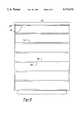
- FIG. 6 is a plan view of a web according to the invention.
- FIG. 1 shows a typical power generation system.
- the gas turbine 10 exhausts to a diffuser 12.
- the exhaust stream continues on through an exhaust elbow 14 up a stack 16.
- Part of the stack shown has a silencer chamber 18.
- the silencer chamber 18 can be located in the vertical exhaust stack of the power plant or can be located along horizontal ducting.
- the exhaust chamber 18 contains a plurality of silencer panels 20 arrayed parallel to the exhaust flow (vertically upwards in FIGS. 1 and 2).
- the silencer panels are spaced apart from one another to form an array 22 allowing exhaust flow between panels.
- the panels are designed to extend across the width of the chamber 18 and arrayed across substantially the depth of the chamber.
- the width of the panels, along with the spacing between panels, is designed to attenuate the noise of the exhaust stream. The width and spacing determines how much attenuation is achieved and at what frequency.
- the silencer panels act as baffles in the exhaust stream, and the acoustical insulation within the panels muffles and attenuates the sounds.
- the silencer panels are intended to maintain their integrity to continue to act as baffles and to continue to contain the acoustic insulation.
- the panels are subjected to high thermal cycling in a corrosive atmosphere of exhaust byproducts, as well as forces generated by a high velocity turbulent exhaust stream.
- the chamber 18 is also equipped with an access door 24 for inspection and/or service functions.
- lifting lugs 26 are attached to the chamber so as to allow installation of a preassembled unit and/or manipulation during servicing.
- the silencer chamber itself can be made of 1/4" thick A36 carbon steel plate for an outer casing and be insulated with known insulation material such as expanded ceramic fiber or basalt fiber or fiberglass which itself is lined (internally) by for example, 11 or 12 gauge stainless steel liner.
- the silencer panels are mounted within the chamber by various means.
- the panels can be placed in an internal ridge at the edge of the silencer chamber (not shown) which will restrict their movement. This is especially preferred in the silencer chambers running along horizontal ducts where the exhaust chamber is horizontal. In situations such as shown in FIG. 2 where the exhaust stream is vertical, the silencer panels can also be affixed by pins in the exhaust stream. In addition, as further discussed below, the silencer panels may be equipped with suspension lift points for ease of transport and installation.
- a U-shaped channel made of stainless steel is welded to form a periphery or frame 28 about the panel.
- This U-shaped channel will remain the outer periphery on the narrow edges of the panel and will be used to help mount the panel within the silencer chamber.
- the channel used to fabricate the upper edge of the panel may also have installed lifting nuts 30 which are threaded to allow easy attachment of cables to lift the assembled panel into and out of place at the final installation point.
- Within the outer periphery and helping to tie together the U-channel to form a framework 32 are webs 34. Turning to FIG. 6, these webs 34 are made of stainless steel and are welded to the U-channel at the periphery.
- the long edges 36 of the webs are bent over to provide additional attachment surface 38, as explained later.
- the web has openings 40 within it to minimize local thermal stresses.
- the large area of the web 42 will be adjacent to acoustical insulation which incidentally acts as thermal insulation.
- the edge forming the additional attachment surface 38 will be directly subject to exhaust gas through the cladding (discussed later) and hence the thermal cycling, while the large areas 42 will only be secondarily subject to the thermal cycling, being insulated by the acoustical insulation. Changes in temperature are initiated at the long edge 36 and attachment surface 38 and migrate from that edge internally. As a result, significant thermal gradients can be established from the outside edge 36 along the large area 42.
- the web By removing portions of the web material and leaving openings 40, the web can heat up faster in response to a given amount of heat from changing temperatures at the long edge 36, resulting in less of a gradient along the area 42 of the web.
- the web must retain its structural integrity, as part of the framework 32. In order to retain structural integrity and allow for thermal expansion more than 50% of the area 42 is removed to achieve these functions. By more than 50% of the area, the surface area along the large internal sides of the web is referred to.
- the openings resulting from the removal of the material can be of many shapes and/or sizes, however, internal corners 44 of the opening 40 should be removed by generous radiusing to eliminate stress concentrations or stress risers.
- septums 46 in the form of stainless steel screening light gage solid sheet can be placed over the web 34.
- the function of the septum 46 is to keep the insulation within the silencer panel from shifting through the openings in the web. This can become of greater importance as the panel is subjected to use and embrittled acoustical insulation can break into smaller pieces.
- the septum is preferably free floating, i.e., not rigidly attached to any portion of the peripheral frame 28 or webbing 34. By allowing the septum to be free floating, thermal stresses due to the septum can be eliminated as it can freely expand or contract in all directions.
- the septum 46 can be integrated with the web 34 by using a heavier gauge screen with small openings. This serves to still minimize stress while also reducing movement of insulation. Such a combined septum-web cannot be free floating if it is to act as part of the framework.
- Acoustical insulation 48 that will also be able to survive the hostile environment of the exhaust stream is placed within the silencer panel.
- acoustical insulation that are preferred are expanded ceramic fibers in a plurality of sheets, the sheets being on the order of 11/2" thick and can be selected from a variety of densities.
- the fibers can be in the form of, for example, fiberglass, mineral wool or basalt fiber.
- a dozen or more layers of insulation 48 may be placed parallel to one another within the panel 20 with the insulation being discontinuous across the web 34.
- the insulation can be covered at the exposed faces with stainless steel screening 50 such as used for the septum.
- the screening can be 40 ⁇ 40 stainless steel 0.0065" thick (0.165 mm).
- Cladding 52 is preferably of perforated stainless steel sheets, such as perforated 14 gauge stainless steel.
- the cladding is supplied in panels and spot welded 56 at its center to the turned over edge or additional attachment surface 38 of the webbing.
- the cladding is preferably gapped between panel 54 prior to welding 58 at the periphery. The welding allows for thermal expansion without excessive structural integrity that could cause the panel to tear itself apart over repeated thermal cycling.
Landscapes
- Engineering & Computer Science (AREA)
- Mechanical Engineering (AREA)
- General Engineering & Computer Science (AREA)
- Exhaust Silencers (AREA)
Abstract
Description
Claims (3)
Priority Applications (3)
| Application Number | Priority Date | Filing Date | Title |
|---|---|---|---|
| US08/625,556 US5715672A (en) | 1996-04-01 | 1996-04-01 | Exhaust silencer panel for gas turbine |
| US08/783,279 US6263998B1 (en) | 1996-04-01 | 1997-01-15 | Exhaust silencer panel |
| US08/967,500 US6056084A (en) | 1996-04-01 | 1997-11-11 | Exhaust silencer panel |
Applications Claiming Priority (1)
| Application Number | Priority Date | Filing Date | Title |
|---|---|---|---|
| US08/625,556 US5715672A (en) | 1996-04-01 | 1996-04-01 | Exhaust silencer panel for gas turbine |
Related Child Applications (2)
| Application Number | Title | Priority Date | Filing Date |
|---|---|---|---|
| US08/783,279 Continuation-In-Part US6263998B1 (en) | 1996-04-01 | 1997-01-15 | Exhaust silencer panel |
| US08/967,500 Division US6056084A (en) | 1996-04-01 | 1997-11-11 | Exhaust silencer panel |
Publications (1)
| Publication Number | Publication Date |
|---|---|
| US5715672A true US5715672A (en) | 1998-02-10 |
Family
ID=24506634
Family Applications (2)
| Application Number | Title | Priority Date | Filing Date |
|---|---|---|---|
| US08/625,556 Expired - Lifetime US5715672A (en) | 1996-04-01 | 1996-04-01 | Exhaust silencer panel for gas turbine |
| US08/967,500 Expired - Lifetime US6056084A (en) | 1996-04-01 | 1997-11-11 | Exhaust silencer panel |
Family Applications After (1)
| Application Number | Title | Priority Date | Filing Date |
|---|---|---|---|
| US08/967,500 Expired - Lifetime US6056084A (en) | 1996-04-01 | 1997-11-11 | Exhaust silencer panel |
Country Status (1)
| Country | Link |
|---|---|
| US (2) | US5715672A (en) |
Cited By (22)
| Publication number | Priority date | Publication date | Assignee | Title |
|---|---|---|---|---|
| EP0854270A1 (en) * | 1997-01-15 | 1998-07-22 | Jason Incorporated | Exhaust silencer panel |
| WO2001096802A1 (en) * | 2000-06-14 | 2001-12-20 | Honeywell International Inc. | Manifold reinforcement webbing for heat exchangers |
| WO2002086294A1 (en) * | 2001-04-24 | 2002-10-31 | Wieser-Linhart Emil A J | Mobile installation for silencing and cleaning exhaust gases of an internal combustion engine |
| US6539702B2 (en) * | 1997-09-25 | 2003-04-01 | Mitsubishi Heavy Industries, Ltd. | Gas turbine exhaust passage and damper system for same having a non-enclosed porous peripheral wall |
| US20030072648A1 (en) * | 2001-05-30 | 2003-04-17 | Han Ming Hui | Outlet silencer structures for turbine |
| US20040088994A1 (en) * | 2002-07-08 | 2004-05-13 | Herbert Schutz | Gas turbine plant with an exhaust gas chimney |
| US20040267373A1 (en) * | 2003-06-25 | 2004-12-30 | Dwyer Kimberly Ann | Assembly tool for modular implants and associated method |
| US20050033444A1 (en) * | 2003-06-25 | 2005-02-10 | Jones Michael C. | Assembly tool for modular implants and associated method |
| US20070298700A1 (en) * | 2006-06-21 | 2007-12-27 | Dipti Datta | Exhaust gas stack |
| US7383918B1 (en) * | 2003-12-31 | 2008-06-10 | Vitai Link, Inc. | Noise suppressor exhaust sound attenuation overhaul and repair kit |
| JP2009185820A (en) * | 2008-02-11 | 2009-08-20 | General Electric Co <Ge> | Exhaust stack for enhancing gas turbine output and power generating system |
| US20110168482A1 (en) * | 2010-01-08 | 2011-07-14 | Laxmikant Merchant | Vane type silencers in elbow for gas turbine |
| US8518050B2 (en) | 2007-10-31 | 2013-08-27 | DePuy Synthes Products, LLC | Modular taper assembly device |
| US8826669B2 (en) | 2011-11-09 | 2014-09-09 | Pratt & Whitney Canada Corp. | Gas turbine exhaust case |
| US8944753B2 (en) | 2011-11-09 | 2015-02-03 | Pratt & Whitney Canada Corp. | Strut mounting arrangement for gas turbine exhaust case |
| US8998919B2 (en) | 2003-06-25 | 2015-04-07 | DePuy Synthes Products, LLC | Assembly tool for modular implants, kit and associated method |
| US9095452B2 (en) | 2010-09-01 | 2015-08-04 | DePuy Synthes Products, Inc. | Disassembly tool |
| US9101495B2 (en) | 2010-06-15 | 2015-08-11 | DePuy Synthes Products, Inc. | Spiral assembly tool |
| US9200537B2 (en) | 2011-11-09 | 2015-12-01 | Pratt & Whitney Canada Corp. | Gas turbine exhaust case with acoustic panels |
| US9504578B2 (en) | 2011-04-06 | 2016-11-29 | Depuy Synthes Products, Inc | Revision hip prosthesis having an implantable distal stem component |
| US9717545B2 (en) | 2007-10-30 | 2017-08-01 | DePuy Synthes Products, Inc. | Taper disengagement tool |
| EP2473706A4 (en) * | 2009-09-01 | 2017-11-08 | Exxonmobil Upstream Research Company | Low emission power generation and hydrocarbon recovery systems and methods |
Families Citing this family (1)
| Publication number | Priority date | Publication date | Assignee | Title |
|---|---|---|---|---|
| US10662839B2 (en) * | 2017-06-28 | 2020-05-26 | General Electric Company | Exhaust stack assemblies with acoustic attenuation features |
Citations (4)
| Publication number | Priority date | Publication date | Assignee | Title |
|---|---|---|---|---|
| US2810449A (en) * | 1955-04-12 | 1957-10-22 | North American Aviation Inc | Sound abatement device for jet engines |
| US3159238A (en) * | 1960-12-01 | 1964-12-01 | Curtiss Wright Corp | Diffuser screen with heat-insulating rungs for exhaust noise suppressor for reactionengines |
| US3185252A (en) * | 1957-07-29 | 1965-05-25 | C W Lemmerman Inc | Jet engine noise attenuator |
| US3688865A (en) * | 1970-11-17 | 1972-09-05 | Cloyd D Smith | Jet engine noise suppressor |
-
1996
- 1996-04-01 US US08/625,556 patent/US5715672A/en not_active Expired - Lifetime
-
1997
- 1997-11-11 US US08/967,500 patent/US6056084A/en not_active Expired - Lifetime
Patent Citations (4)
| Publication number | Priority date | Publication date | Assignee | Title |
|---|---|---|---|---|
| US2810449A (en) * | 1955-04-12 | 1957-10-22 | North American Aviation Inc | Sound abatement device for jet engines |
| US3185252A (en) * | 1957-07-29 | 1965-05-25 | C W Lemmerman Inc | Jet engine noise attenuator |
| US3159238A (en) * | 1960-12-01 | 1964-12-01 | Curtiss Wright Corp | Diffuser screen with heat-insulating rungs for exhaust noise suppressor for reactionengines |
| US3688865A (en) * | 1970-11-17 | 1972-09-05 | Cloyd D Smith | Jet engine noise suppressor |
Cited By (46)
| Publication number | Priority date | Publication date | Assignee | Title |
|---|---|---|---|---|
| EP0854270A1 (en) * | 1997-01-15 | 1998-07-22 | Jason Incorporated | Exhaust silencer panel |
| US6966172B2 (en) | 1997-09-25 | 2005-11-22 | Mitsubishi Heavy Industries, Ltd. | Gas turbine exhaust passage and damper system for same |
| US6539702B2 (en) * | 1997-09-25 | 2003-04-01 | Mitsubishi Heavy Industries, Ltd. | Gas turbine exhaust passage and damper system for same having a non-enclosed porous peripheral wall |
| US6668540B2 (en) | 1997-09-25 | 2003-12-30 | Mitsubishi Heavy Industries, Ltd. | Gas turbine exhaust passage and damper system for same |
| US20050188673A1 (en) * | 1997-09-25 | 2005-09-01 | Mitsubishi Heavy Industries, Ltd. | Gas turbine exhaust passage and damper system for same |
| WO2001096802A1 (en) * | 2000-06-14 | 2001-12-20 | Honeywell International Inc. | Manifold reinforcement webbing for heat exchangers |
| WO2002086294A1 (en) * | 2001-04-24 | 2002-10-31 | Wieser-Linhart Emil A J | Mobile installation for silencing and cleaning exhaust gases of an internal combustion engine |
| US20030072648A1 (en) * | 2001-05-30 | 2003-04-17 | Han Ming Hui | Outlet silencer structures for turbine |
| US6802690B2 (en) * | 2001-05-30 | 2004-10-12 | M & I Heat Transfer Products, Ltd. | Outlet silencer structures for turbine |
| US20040088994A1 (en) * | 2002-07-08 | 2004-05-13 | Herbert Schutz | Gas turbine plant with an exhaust gas chimney |
| US7089727B2 (en) * | 2002-07-08 | 2006-08-15 | Siemens Aktiengesellschaft | Gas turbine plant with an exhaust gas chimney |
| US8685036B2 (en) | 2003-06-25 | 2014-04-01 | Michael C. Jones | Assembly tool for modular implants and associated method |
| US20040267373A1 (en) * | 2003-06-25 | 2004-12-30 | Dwyer Kimberly Ann | Assembly tool for modular implants and associated method |
| US20080091212A1 (en) * | 2003-06-25 | 2008-04-17 | Depuy Products, Inc. | Assembly tool for modular implants and associated method |
| US9381097B2 (en) | 2003-06-25 | 2016-07-05 | DePuy Synthes Products, Inc. | Assembly tool for modular implants, kit and associated method |
| US20050033444A1 (en) * | 2003-06-25 | 2005-02-10 | Jones Michael C. | Assembly tool for modular implants and associated method |
| US8998919B2 (en) | 2003-06-25 | 2015-04-07 | DePuy Synthes Products, LLC | Assembly tool for modular implants, kit and associated method |
| US8419799B2 (en) | 2003-06-25 | 2013-04-16 | Depuy Products, Inc. | Assembly tool for modular implants and associated method |
| US7383918B1 (en) * | 2003-12-31 | 2008-06-10 | Vitai Link, Inc. | Noise suppressor exhaust sound attenuation overhaul and repair kit |
| US20070298700A1 (en) * | 2006-06-21 | 2007-12-27 | Dipti Datta | Exhaust gas stack |
| US9717545B2 (en) | 2007-10-30 | 2017-08-01 | DePuy Synthes Products, Inc. | Taper disengagement tool |
| US9119601B2 (en) | 2007-10-31 | 2015-09-01 | DePuy Synthes Products, Inc. | Modular taper assembly device |
| US8518050B2 (en) | 2007-10-31 | 2013-08-27 | DePuy Synthes Products, LLC | Modular taper assembly device |
| JP2009185820A (en) * | 2008-02-11 | 2009-08-20 | General Electric Co <Ge> | Exhaust stack for enhancing gas turbine output and power generating system |
| EP2473706A4 (en) * | 2009-09-01 | 2017-11-08 | Exxonmobil Upstream Research Company | Low emission power generation and hydrocarbon recovery systems and methods |
| US8230967B2 (en) | 2010-01-08 | 2012-07-31 | General Electric Company | Vane type silencers in elbow for gas turbine |
| US8087491B2 (en) | 2010-01-08 | 2012-01-03 | General Electric Company | Vane type silencers in elbow for gas turbine |
| US20110168482A1 (en) * | 2010-01-08 | 2011-07-14 | Laxmikant Merchant | Vane type silencers in elbow for gas turbine |
| US10166118B2 (en) | 2010-06-15 | 2019-01-01 | DePuy Synthes Products, Inc. | Spiral assembly tool |
| US9101495B2 (en) | 2010-06-15 | 2015-08-11 | DePuy Synthes Products, Inc. | Spiral assembly tool |
| US10292837B2 (en) | 2010-09-01 | 2019-05-21 | Depuy Synthes Products Inc. | Disassembly tool |
| US9095452B2 (en) | 2010-09-01 | 2015-08-04 | DePuy Synthes Products, Inc. | Disassembly tool |
| US9867720B2 (en) | 2010-09-01 | 2018-01-16 | DePuy Synthes Products, Inc. | Disassembly tool |
| US9737405B2 (en) | 2011-04-06 | 2017-08-22 | DePuy Synthes Products, Inc. | Orthopaedic surgical procedure for implanting a revision hip prosthesis |
| US9597188B2 (en) | 2011-04-06 | 2017-03-21 | DePuy Synthes Products, Inc. | Version-replicating instrument and orthopaedic surgical procedure for using the same to implant a revision hip prosthesis |
| US9504578B2 (en) | 2011-04-06 | 2016-11-29 | Depuy Synthes Products, Inc | Revision hip prosthesis having an implantable distal stem component |
| US9949833B2 (en) | 2011-04-06 | 2018-04-24 | DePuy Synthes Products, Inc. | Finishing RASP and orthopaedic surgical procedure for using the same to implant a revision hip prosthesis |
| US10064725B2 (en) | 2011-04-06 | 2018-09-04 | DePuy Synthes Products, Inc. | Distal reamer for use during an orthopaedic surgical procedure to implant a revision hip prosthesis |
| US10226345B2 (en) | 2011-04-06 | 2019-03-12 | DePuy Synthes Products, Inc. | Version-replicating instrument and orthopaedic surgical procedure for using the same to implant a revision hip prosthesis |
| US10603173B2 (en) | 2011-04-06 | 2020-03-31 | DePuy Synthes Products, Inc. | Orthopaedic surgical procedure for implanting a revision hip prosthesis |
| US10772730B2 (en) | 2011-04-06 | 2020-09-15 | DePuy Synthes Products, Inc. | Finishing rasp and orthopaedic surgical procedure for using the same to implant a revision hip prosthesis |
| US10888427B2 (en) | 2011-04-06 | 2021-01-12 | DePuy Synthes Products, Inc. | Distal reamer for use during an orthopaedic surgical procedure to implant a revision hip prosthesis |
| US10925739B2 (en) | 2011-04-06 | 2021-02-23 | DePuy Synthes Products, Inc. | Version-replicating instrument and orthopaedic surgical procedure for using the same to implant a revision hip prosthesis |
| US9200537B2 (en) | 2011-11-09 | 2015-12-01 | Pratt & Whitney Canada Corp. | Gas turbine exhaust case with acoustic panels |
| US8944753B2 (en) | 2011-11-09 | 2015-02-03 | Pratt & Whitney Canada Corp. | Strut mounting arrangement for gas turbine exhaust case |
| US8826669B2 (en) | 2011-11-09 | 2014-09-09 | Pratt & Whitney Canada Corp. | Gas turbine exhaust case |
Also Published As
| Publication number | Publication date |
|---|---|
| US6056084A (en) | 2000-05-02 |
Similar Documents
| Publication | Publication Date | Title |
|---|---|---|
| US5715672A (en) | Exhaust silencer panel for gas turbine | |
| US6263998B1 (en) | Exhaust silencer panel | |
| US6539702B2 (en) | Gas turbine exhaust passage and damper system for same having a non-enclosed porous peripheral wall | |
| US2989136A (en) | Sound attenuation | |
| RU2154133C2 (en) | Ventilated multilayer panel with cellular filler | |
| US6439340B1 (en) | Acoustically treated structurally reinforced sound absorbing panel | |
| EP1862605B1 (en) | Thermal-acoustic enclosure | |
| US7047725B2 (en) | Assembly and method for aircraft engine noise reduction | |
| US20100276548A1 (en) | Acoustic processing structure particularly adapted to the air inlet of an aircraft nacelle | |
| US4228624A (en) | Heat-sound insulating wall | |
| CA1272687A (en) | Exhaust silencer for high-power gas turbines | |
| US20070009728A1 (en) | Sound absorbing device for ultra-low frequency sound | |
| US3704762A (en) | Gas turbine exhaust silencer and support | |
| FI3932795T3 (en) | Ship comprising a system for reducing the vibrations originating from the casing and method for building said ship | |
| US3762498A (en) | Gas turbine exhaust silencer | |
| JP2006105052A (en) | Method and device for installing sound insulating enclosure | |
| JPH07224685A (en) | Silencer for gas turbine | |
| JP2903834B2 (en) | Soundproofing | |
| US5125870A (en) | Flue insulation assembly | |
| GB2204916A (en) | Gaseous flow silencer | |
| JP2004094065A (en) | Noise reducing device and exhaust device | |
| US10662839B2 (en) | Exhaust stack assemblies with acoustic attenuation features | |
| KR102257510B1 (en) | Noise Reduction system for Stucture | |
| CN210984260U (en) | Noise reduction device of air cooler | |
| US20020162703A1 (en) | Q-pack silencer |
Legal Events
| Date | Code | Title | Description |
|---|---|---|---|
| AS | Assignment |
Owner name: BRADEN MANUFACTURING (A UNIT OF JASON INCORPORATED Free format text: ASSIGNMENT OF ASSIGNORS INTEREST;ASSIGNORS:SCHOCKEMOEHL, GENE F.;FARABEE, LELAND MATT;MILLS, THOMAS RICHARD;AND OTHERS;REEL/FRAME:007951/0447 Effective date: 19960319 |
|
| STCF | Information on status: patent grant |
Free format text: PATENTED CASE |
|
| CC | Certificate of correction | ||
| AS | Assignment |
Owner name: PARIBAS, NEW YORK Free format text: MERGER;ASSIGNOR:BRADEN MANUFACTURING, L.L.C.;REEL/FRAME:009342/0933 Effective date: 19980608 |
|
| AS | Assignment |
Owner name: BANKERS TRUST COMPANY, AS ADMINISTRATIVE AGENT, NE Free format text: SECURITY INTEREST;ASSIGNOR:BRADEN MANUFACTURING, L.L.C.;REEL/FRAME:011089/0358 Effective date: 20000801 Owner name: BRADEN MANUFACTURING, L.L.C., A DELAWARE LIMITED L Free format text: RELEASE;ASSIGNOR:BNP PARIBAS, AS COLLATERAL AGENT;REEL/FRAME:011084/0854 Effective date: 20000801 |
|
| FPAY | Fee payment |
Year of fee payment: 4 |
|
| AS | Assignment |
Owner name: BANK OF AMERICA, N.A., AS ADMINISTRATIVE AGENT, IL Free format text: ASSIGNMENT OF ASSIGNORS INTEREST;ASSIGNOR:GLOBAL POWER EQUIPMENT GROUP, INC.;REEL/FRAME:015953/0011 Effective date: 20041001 |
|
| FEPP | Fee payment procedure |
Free format text: PAYOR NUMBER ASSIGNED (ORIGINAL EVENT CODE: ASPN); ENTITY STATUS OF PATENT OWNER: LARGE ENTITY |
|
| FPAY | Fee payment |
Year of fee payment: 8 |
|
| AS | Assignment |
Owner name: MORGAN STANLEY & CO. INCORPORATED, NEW YORK Free format text: SECURITY AGREEMENT;ASSIGNOR:BRADEN MANUFACTURING, L.L.C.;REEL/FRAME:020393/0580 Effective date: 20080122 Owner name: BRADEN MANUFACTURING, L.L.C., MASSACHUSETTS Free format text: PATENT RELEASE;ASSIGNOR:DEUTSCHE BANK TRUST COMPANY AMERICAS, AS ADMINISTRATIVE AGENT;REEL/FRAME:020393/0217 Effective date: 20080122 Owner name: BRADEN MANUFACTURING, L.L.C., MASSACHUSETTS Free format text: PATENT RELEASE;ASSIGNOR:BANK OF AMERICA, N.A., AS ADMINISTRATIVE AGENT;REEL/FRAME:020393/0229 Effective date: 20080122 |
|
| AS | Assignment |
Owner name: BRADEN MANUFACTURING, L.L.C., A DELAWARE LIMITED L Free format text: ASSIGNMENT OF ASSIGNORS INTEREST;ASSIGNOR:BRADEN NEVADA, INC., A NEVADA CORPORATION;REEL/FRAME:020532/0157 Effective date: 19980605 Owner name: JASON NEVADA, INC., A NEVADA CORPORATION, WISCONSI Free format text: ASSIGNMENT OF ASSIGNORS INTEREST;ASSIGNOR:JASON INCORPORATED, A WISCONSIN CORPORATION;REEL/FRAME:020525/0990 Effective date: 19980605 Owner name: BRADEN NEVADA, INC., A NEVADA CORPORATION, WISCONS Free format text: ASSIGNMENT OF ASSIGNORS INTEREST;ASSIGNOR:JASON NEVADA, INC., A NEVADA CORPORATION;REEL/FRAME:020532/0150 Effective date: 19980605 |
|
| FPAY | Fee payment |
Year of fee payment: 12 |
|
| AS | Assignment |
Owner name: BRADEN MANUFACTURING, L.L.C., OKLAHOMA Free format text: RELEASE BY SECURED PARTY;ASSIGNOR:MORGAN STANLEY & CO. LLC;REEL/FRAME:027742/0763 Effective date: 20120221 |
|
| AS | Assignment |
Owner name: WELLS FARGO BANK, NATIONAL ASSOCIATION, AS ADMINIS Free format text: SECURITY AGREEMENT;ASSIGNOR:BRADEN MANUFACTURING, L.L.C.;REEL/FRAME:029229/0101 Effective date: 20120221 |
|
| AS | Assignment |
Owner name: WELLS FARGO BANK, NATIONAL ASSOCIATION, AS ADMINIS Free format text: SECURITY AGREEMENT;ASSIGNOR:BRADEN MANUFACTURING, L.L.C.;REEL/FRAME:031720/0972 Effective date: 20131111 |
|
| AS | Assignment |
Owner name: WELLS FARGO BANK, NATIONAL ASSOCIATION, AS ADMINIS Free format text: SECURITY INTEREST;ASSIGNOR:BRADEN MANUFACTURING, L.L.C.;REEL/FRAME:034823/0920 Effective date: 20150109 |
|
| AS | Assignment |
Owner name: KOONTZ-WAGNER CUSTOM CONTROLS HOLDINGS LLC, INDIAN Free format text: RELEASE BY SECURED PARTY;ASSIGNOR:CENTRE LANE PARTNERS MASTER CREDIT FUND II, L. P., AS THE SUCCESSOR IN INTEREST TO WELLS FARGO BANK, NATIONAL ASSOCIATION;REEL/FRAME:043444/0773 Effective date: 20170717 Owner name: GLOBAL POWER EQUIPMENT GROUP INC., TEXAS Free format text: RELEASE BY SECURED PARTY;ASSIGNOR:CENTRE LANE PARTNERS MASTER CREDIT FUND II, L. P., AS THE SUCCESSOR IN INTEREST TO WELLS FARGO BANK, NATIONAL ASSOCIATION;REEL/FRAME:043444/0773 Effective date: 20170717 Owner name: WILLIAMS PLANT SERVICES, LLC, GEORGIA Free format text: RELEASE BY SECURED PARTY;ASSIGNOR:CENTRE LANE PARTNERS MASTER CREDIT FUND II, L. P., AS THE SUCCESSOR IN INTEREST TO WELLS FARGO BANK, NATIONAL ASSOCIATION;REEL/FRAME:043444/0773 Effective date: 20170717 Owner name: WILLIAMS GLOBAL SERVICES, INC., GEORGIA Free format text: RELEASE BY SECURED PARTY;ASSIGNOR:CENTRE LANE PARTNERS MASTER CREDIT FUND II, L. P., AS THE SUCCESSOR IN INTEREST TO WELLS FARGO BANK, NATIONAL ASSOCIATION;REEL/FRAME:043444/0773 Effective date: 20170717 Owner name: WILLIAMS INDUSTRIAL SERVICES GROUP, L. L. C., GEOR Free format text: RELEASE BY SECURED PARTY;ASSIGNOR:CENTRE LANE PARTNERS MASTER CREDIT FUND II, L. P., AS THE SUCCESSOR IN INTEREST TO WELLS FARGO BANK, NATIONAL ASSOCIATION;REEL/FRAME:043444/0773 Effective date: 20170717 Owner name: BRADEN MANUFACTURING, L. L. C., OKLAHOMA Free format text: RELEASE BY SECURED PARTY;ASSIGNOR:CENTRE LANE PARTNERS MASTER CREDIT FUND II, L. P., AS THE SUCCESSOR IN INTEREST TO WELLS FARGO BANK, NATIONAL ASSOCIATION;REEL/FRAME:043444/0773 Effective date: 20170717 Owner name: WILLIAMS INDUSTRIAL SERVICES, LLC, GEORGIA Free format text: RELEASE BY SECURED PARTY;ASSIGNOR:CENTRE LANE PARTNERS MASTER CREDIT FUND II, L. P., AS THE SUCCESSOR IN INTEREST TO WELLS FARGO BANK, NATIONAL ASSOCIATION;REEL/FRAME:043444/0773 Effective date: 20170717 Owner name: CONSTRUCTION & MAINTENANCE PROFESSIONALS, LLC, GEO Free format text: RELEASE BY SECURED PARTY;ASSIGNOR:CENTRE LANE PARTNERS MASTER CREDIT FUND II, L. P., AS THE SUCCESSOR IN INTEREST TO WELLS FARGO BANK, NATIONAL ASSOCIATION;REEL/FRAME:043444/0773 Effective date: 20170717 Owner name: WILLIAMS SPECIALTY SERVICES, LLC, GEORGIA Free format text: RELEASE BY SECURED PARTY;ASSIGNOR:CENTRE LANE PARTNERS MASTER CREDIT FUND II, L. P., AS THE SUCCESSOR IN INTEREST TO WELLS FARGO BANK, NATIONAL ASSOCIATION;REEL/FRAME:043444/0773 Effective date: 20170717 |