US5716389A - Cardiac ablation catheter arrangement with movable guidewire - Google Patents
Cardiac ablation catheter arrangement with movable guidewire Download PDFInfo
- Publication number
- US5716389A US5716389A US08/559,816 US55981695A US5716389A US 5716389 A US5716389 A US 5716389A US 55981695 A US55981695 A US 55981695A US 5716389 A US5716389 A US 5716389A
- Authority
- US
- United States
- Prior art keywords
- guide
- catheter body
- wire
- distal end
- catheter
- Prior art date
- Legal status (The legal status is an assumption and is not a legal conclusion. Google has not performed a legal analysis and makes no representation as to the accuracy of the status listed.)
- Expired - Fee Related
Links
Images


Classifications
-
- A—HUMAN NECESSITIES
- A61—MEDICAL OR VETERINARY SCIENCE; HYGIENE
- A61N—ELECTROTHERAPY; MAGNETOTHERAPY; RADIATION THERAPY; ULTRASOUND THERAPY
- A61N1/00—Electrotherapy; Circuits therefor
- A61N1/02—Details
- A61N1/04—Electrodes
- A61N1/06—Electrodes for high-frequency therapy
-
- A—HUMAN NECESSITIES
- A61—MEDICAL OR VETERINARY SCIENCE; HYGIENE
- A61B—DIAGNOSIS; SURGERY; IDENTIFICATION
- A61B5/00—Measuring for diagnostic purposes; Identification of persons
- A61B5/24—Detecting, measuring or recording bioelectric or biomagnetic signals of the body or parts thereof
- A61B5/25—Bioelectric electrodes therefor
- A61B5/279—Bioelectric electrodes therefor specially adapted for particular uses
- A61B5/28—Bioelectric electrodes therefor specially adapted for particular uses for electrocardiography [ECG]
- A61B5/283—Invasive
- A61B5/287—Holders for multiple electrodes, e.g. electrode catheters for electrophysiological study [EPS]
-
- A—HUMAN NECESSITIES
- A61—MEDICAL OR VETERINARY SCIENCE; HYGIENE
- A61N—ELECTROTHERAPY; MAGNETOTHERAPY; RADIATION THERAPY; ULTRASOUND THERAPY
- A61N1/00—Electrotherapy; Circuits therefor
- A61N1/02—Details
- A61N1/04—Electrodes
- A61N1/05—Electrodes for implantation or insertion into the body, e.g. heart electrode
- A61N1/056—Transvascular endocardial electrode systems
-
- A—HUMAN NECESSITIES
- A61—MEDICAL OR VETERINARY SCIENCE; HYGIENE
- A61N—ELECTROTHERAPY; MAGNETOTHERAPY; RADIATION THERAPY; ULTRASOUND THERAPY
- A61N1/00—Electrotherapy; Circuits therefor
- A61N1/02—Details
- A61N1/04—Electrodes
- A61N1/05—Electrodes for implantation or insertion into the body, e.g. heart electrode
- A61N1/0587—Epicardial electrode systems; Endocardial electrodes piercing the pericardium
-
- A—HUMAN NECESSITIES
- A61—MEDICAL OR VETERINARY SCIENCE; HYGIENE
- A61B—DIAGNOSIS; SURGERY; IDENTIFICATION
- A61B2562/00—Details of sensors; Constructional details of sensor housings or probes; Accessories for sensors
- A61B2562/04—Arrangements of multiple sensors of the same type
- A61B2562/043—Arrangements of multiple sensors of the same type in a linear array
Definitions
- This invention relates to catheters, and more particularly to catheters for cardiac ablation.
- U.S. Pat. No. 4,641,649 issued Feb. 10, 1987 in the name of Walinsky et al. describes a catheter and method for cardiac ablation.
- the symptoms of tachycardia or cardiac disrhythmya may require destruction of tissue on the interior surface of the heart, as for example to the bundle of His, an aberrant conducting fiber tract, or to the ectopic focus.
- the catheter used for this purpose includes a coaxial transmission line terminating in an antenna or probe. The method therein described is to insert the coaxial transmission line transluminally into the heart, and then to adjust the location of the probe by observing action potentials which appear between the probe and an exposed electrode on the exterior of the distal end of the catheter body.
- the sensing and ablation arrangement allows location and cardiac ablation on a patient.
- the sensing and ablation arrangement includes:
- a guide-wire lumen extending from a location near the proximal end to the distal end of the catheter body, the guide-wire lumen having a particular transverse dimension throughout a principal portion of its length which is selected to accommodate a guide wire, the guide-wire lumen also having a predetermined diameter at the distal end, which is no less than the particular transverse dimension of the guide-wire lumen;
- the guide wire including an elongated body portion extending through the guide-wire lumen of the catheter in a manner axially movable in relation thereto, and in a manner such that the guide wire and the catheter body can be completely separated from each other, the guide wire further comprises an enlarged distal end portion larger than the predetermined diameter, whereby the distal end of the guide-wire lumen is occluded when the guide-wire is fully retracted with the enlarged distal end portion abutting the distal end of the guide-wire lumen;
- an action potential sensing arrangement adapted for, in a sensing mode of operation of the sensing and ablation arrangement, being coupled to the proximal end of the guide wire and to the electrical terminus arrangement, for sensing action potentials appearing between the enlarged end portion of the guide wire and the first electrode, whereby the enlarged end portion of the guide wire may be moved to a cardiac location identifiable by the action potentials;
- an RF signal generating arrangement adapted for, in an ablation mode of operation of the sensing and ablation arrangement, being coupled to the proximal end of the guide wire and to the contact plate, for causing RF signal energy to be guided to the cardiac location, for causing RF current to flow between the contact plate and the enlarged distal end portion of the guidewire at the cardiac location, resulting in ablation of cardiac material at the cardiac location, but not at the contact plate.
- at least a distal portion of the body portion of the guide wire is surrounded by electrical insulation, leaving at least a distal portion of the enlarged distal end portion of the guide wire exposed.
- the catheter itself is not as stiff as a correspondingly thick coaxial catheter, and so is more readily moved to the desired location.
- the axially movable, electrically conductive guidewire allows the guidewire to be extended distally beyond the distal end of the catheter body, and it is much more flexible than the prior-art coaxial cable with nonmovable center conductor, which would otherwise have to be introduced as an entirety into the same region as the distal end of the guidewire alone.
- RF power RF signal
- a method according to the invention includes the steps of:
- a guide-wire lumen extending from a location near the proximal end to the distal end of the first catheter body, the guide-wire lumen having a particular transverse dimension throughout a principal portion of its length which is selected to accommodate a guide wire, the guide-wire lumen also having a predetermined diameter at the distal end, which is no smaller than the particular transverse dimension of the guide-wire lumen;
- an electrically conductive guide wire longer than the first catheter body the guide wire including an elongated body portion extending through the guide-wire lumen of the first catheter body in such a manner as to allow axial motion in relation thereto, and in a manner such that the guide wire and the first catheter body can be completely separated from each other, the guide wire further comprising an enlarged distal end portion larger than the predetermined diameter, whereby the distal end of the guide-wire lumen is occluded when the guide-wire is fully retracted with the enlarged distal end portion abutting the distal end of the guide-wire lumen;
- FIG. 1a is a simplified perspective or isometric representation of an action potential sensing and RF ablation arrangement according to the invention, in which a catheter includes a guidewire lumen, an external electrode, and a distal end
- FIG. 1b is a longitudinal cross-section of a distal portion of the catheter of FIG. 1a
- FIGS. 1c and 1d are transverse cross-sections of the catheter of FIG. 1a at locations 1c--1c and 1d--1d near its distal end
- FIG. 1e is a cross-section similar to that of FIG. 1b illustrating a slightly different guidewire lumen configuration
- FIG. 2a is a simplified perspective or isometric view of a catheter according to the invention, in which two external electrodes are provided, and one makes contact by means of the guidewire in its retracted position, and FIG. 2b is a longitudinal cross-section thereof looking in direction 2b--2b;
- FIG. 3a is a simplified perspective or isometric view of a sensing and ablation arrangement according to the invention, in which the catheter includes two external electrodes as in FIGS. 2a and 2b, but in which both external electrodes have separate electrical connections through the catheter body to the proximal end, FIGS. 3b and 3c are longitudinal and transverse cross-sections, respectively, of the arrangement of FIG. 3anear the distal end thereof;
- FIG. 4 is a perspective or isometric view of the distal end of a catheter according to the invention, in which the enlarged distal end of the guidewire has the same diameter as the body of the catheter;
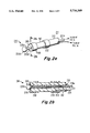
- FIG. 5 is a perspective or isometric view of the distal end of a catheter according to the invention, in which the enlarged distal end of the guidewire has a smaller diameter than the body of the catheter;
- FIG. 6a is a perspective or isometric view of the distal end of a catheter according to the invention, partially cut away to reveal interior details, in which the enlarged distal end of the guidewire has a larger diameter than the body of the catheter, and FIG. 6b is a longitudinal cross-section of the arrangement of FIG. 6A;
- FIGS. 7a, 7b, and 7c illustrate different shapes into which an enlarged disk guidewire end can be formed
- FIGS. 8a, 8b, and 8c illustrate steps in using the catheter body described in conjunction with FIGS. 1a-1e to place the guidewire in the proper location, following which a catheter body with an outer conductor of a coaxial transmission line is slipped over the in-place guidewire, to perform ablation.
- FIG. 1a is a perspective or isometric view of an action potential sensing and electrical ablation arrangement 10 according to the invention.
- the arrangement of FIG. 1a is intended for use in ablation of particular portions of the interior surface of the heart of a patient.
- a catheter 11 includes an elongated, flexible, electrically nonconductive body 12, which extends from a proximal end 14 to a distal end 16.
- Body 12 defines an elongated guidewire lumen 18 which extends from proximal end 14 to distal end 16.
- An electrically conductive guidewire designated generally as 20 includes an elongated body portion 20a, which is long enough to, when guidewire 20 is assembled with catheter body 12, extend through body 12, and extend beyond body 12 at both ends.
- Guidewire 20 also includes an enlarged end portion 20b, which may take the form of a rounded "doorknob" or "button” as illustrated.
- a layer, sheath or tube 21 of dielectric material which, together with dielectric body 12, insulates the guidewire so that only enlarged end (button) portion 20b of the guidewire makes electrical contact with the body of a patient.
- the insulating sheath 21 extends all the way through the lumen 18 of body 12, and protrudes from both the proximal and distal ends.
- guidewire body 20a extends beyond the end of insulating sheath 21, leaving a conductive portion of the guidewire available as a contact or terminal 25.
- An annular or ring electrode 22 is affixed to catheter body 12a near the distal end 16 of catheter 11 of FIG. 1a. Electrode 22 is exposed to the exterior of the catheter, and is electrically connected to the proximal end 14 of catheter 11 by an elongated conductive wire or path 28 which extends through catheter body 12 from electrode 22 to the proximal end 14, running parallel to the guidewire lumen 18, as can be seen in FIG. 1c. At electrode 22, a radial conductive arrangement 29 connects wire 28 to electrode 22, as can best be seen in FIG. 1d.
- the exterior diameter of guidewire body 20a and insulating sheath 21 is illustrated as d1 in FIG. 1b, and the interior diameter of guidewire lumen 18 of catheter body 12a is illustrated as D1.
- Dimensions D1 and d1 are selected, taking into consideration the materials of which they are made, so that the guidewire 20 with its insulating sheath can be moved relative to catheter body 20a, in the direction of arrows 30 of FIG. 1a.
- guidewire 20 can be removed completely from lumen 18, if desired.
- the distal end of guidewire 20 can be retracted, so that the curved proximal or "rear" portion of enlarged end portion 20b of catheter 20 butts against the distal end of catheter body 12, as illustrated in FIG.
- an action potential sensing arrangement is illustrated as a block 26, which includes two electrical leads 27a, 27b, which are illustrated as being connectable to proximal terminals 24 and 25 of guidewire 20 and electrode connection wire 28, respectively.
- action potentials appearing across (or between) the enlarged distal end 20b of guidewire 20 and electrode 22 can be sensed by action potential sensing arrangement 26.
- This sensing mode of operation allows the location of a particular portion of the heart's surface to be located, prior to operating in a second or ablation mode.
- ablation radio-frequency (RF) electromagnetic generator (RF signal generator) 36 is connected to proximal guidewire terminal 25 and to a conductive plate 32.
- Conductive plate 32 is in adjacent to, or preferably in contact with, the patient's thorax, and preferably his back. As is known to those skilled in the art, resistance reducing materials can be placed at the interface to aid in providing uniform contact over the surface area of the plate.
- RF generator 36 is then energized to produce a particular amount of ablation energy, by controlling the magnitude of the RF energy (power) or the duration of application of the power, or preferably both.
- a low-pass filter (LPF) 42 may be used with sensing instrument 26, if desired, to reduce the amount of ablation RF signal entering sensor 26. If the impedance presented by RF generator 36 at low (action potential) frequencies is low enough to adversely affect the signal readings by action potential sensor 26, a high-pass filter (HPF) 44, presenting a high low-frequency impedance, may be coupled to generator conductors 34 and 38. Such a filter might be as simple as a capacitor coupled in series with conductor 38.
- FIG. 1e is a longitudinal cross-section of the distal end of a catheter similar to that of FIGS. 1a-1d, and corresponding elements are designated by like reference numbers.
- insulating or dielectric sheath 21 surrounds the distal end of body portion 20a of guidewire 20, but does not extend all the way to the proximal end 14 of catheter 11. Instead, sheath 21 extends only over a limited region, designated 60a in FIG. 1e, which is somewhat longer than the maximum expected distal extension of guidewire 20 from catheter body 12. Sheath 21 of FIG. 1e thus insulates all but the exposed button 20b of the guidewire, when the guidewire does not have an insulating sheath extending all the way to proximal end 14.
- the exterior diameter of the guidewire-and-sheath (the combination of 20a and 21) is d2 in region 60a, and the diameter of guidewire lumen 18 is D2 in corresponding region 60b.
- the guidewire body 20a has no sheath, so its diameter is d1, and the corresponding diameter of lumen 18 is D1.
- the diameter of lumen 18 is D1 at the proximal end, and D2 at the distal end, where D2 is greater than D1.
- FIG. 2a is a simplified perspective or isometric view of a distal portion 216 of the body 212 of a catheter 211
- FIG. 2b is a longitudinal cross-section thereof looking in direction 2b--2b of FIG. 2a.
- Catheter 211 of FIGS. 2a and 2b may be substituted for catheter 11 in the sensing and ablation arrangement of FIGS. 1a, 1b, 1c, and 1d.
- catheter body 211 defines a guidewire lumen 218, dimensioned to accommodate a guidewire body 220a, and its sheath 221, if present, with a sliding fit.
- a first exposed annular electrode 222 is connected by a conductive path 229 to a wire conductor 228 extending through dielectric body 212.
- Wire 228 and guidewire 220 extend to terminals 24 and 25 at the proximal end of the catheter, for connection to action potential sensor 26 and RF generator 36 in place of catheter 11.
- Catheter 211 includes a further electrode 298 which covers a substantial portion of the distal end face 296 of catheter 211, including at least a portion of recess 240, and which also wraps around onto the cylindrical portion of body 212. This arrangement increases the effective conductive sensing surface area when the guidewire is fully retracted, because guidewire button 220b electrically contacts electrode 298. Such a larger surface area, in turn, makes it easier to perform coarse positioning of the distal end of the guidewire, before the final position of the button is established, and also increases the surface area for energy delivery for ablation.
- FIGS. 3a and 3b The arrangement of FIGS. 3a and 3b is similar to that of FIGS. 1a and 1b, and corresponding elements are designated by like reference numerals.
- the arrangement of FIGS. 3a and 3b differs from that of FIGS. 1a and 1b in that it includes an additional external annular electrode 322, which is connected by a contact 329 and a second longitudinal wire 328 to the proximal end 14 of the catheter.
- the connections of action potential sensor 26 leads 27a and 27b are to wires 28 and 328, respectively, so that the action potential sensor 26 is completely isolated from RF generator 36, which is connected to plate 32 and to guidewire body 20a.
- FIG. 3c illustrates a transverse cross-section of the catheter of FIG. 3a, looking in direction 3c--3c.
- FIG. 4 is a simplified perspective or isometric view of a catheter according to the invention, in which a guidewire includes a body portion 420a and a cylindrical "button" portion 420b defining a diameter D which equals the diameter of body portion 12 of the catheter.
- FIG. 5 is a simplified perspective or isometric view of a catheter according to the invention, in which a guidewire includes a body portion 520a and a cylindrical "button" portion 520b defining a diameter D4 which is smaller than the diameter D3 of body portion 12 of the catheter.
- the distal end face 596 of the catheter body 12 of FIG. 5 defines a recess or cavity 540, dimensioned to accommodate button 520b both in diameter and in depth, so when the guidewire is retracted, button 520b fills cavity 540, leaving the end face flush.
- the catheter of FIG. 5 includes an annular electrode 522 similar to electrode 322 of FIGS. 3a and 3b.
- the guidewire includes a body portion 620a and a cylindrical button 620bdefining a diameter D5 greater than the diameter D6 of the body 12 of the catheter.
- Button 620b defines a cavity 694, which has a diameter sufficient to accommodate the end of catheter body 12.
- FIG. 7a is a simplified illustration of the distal end of a guidewire 720 according to the invention including a body 720a, in which the button 720b is a thin disk.
- the disk has been manually bent into a "parasol" shape, and in FIG. 7c, the bending has been continued past the shape of FIG. 7b.
- Such shapes may be convenient for various different conditions, and save cost by allowing manual shaping as conditions require, without changing catheters.
- the guidewire can be fully opened as in FIG. 7a, or retracted as in FIG. 7c. When fully retracted, the guidewire can be removed from the catheter and a new guidewire introduced into the catheter.
- FIG. 8a illustrates a catheter arrangement, similar to that of FIG. 1a, in which the electrically conductive guidewire is in place in the body of a patient, with its enlarged distal end in contact with the desired location to be ablated.
- elements corresponding to those of FIG. 1a are designated by like numerals, and 810 designates portions of the patient's heart, defining an access lumen 812 through which the catheter is brought near the region 814 to be ablated, which is located, as described above, by sensing action potentials.
- the catheter body 12 has been removed from around the guidewire 20, which remains in place, in contact with point 814.
- Second catheter body 890 illustrates the fitting over the guidewire 20 of a second catheter body 890.
- the length of second catheter body 890 must be no longer than the maximum length of the body 12 which was removed, as mentioned above.
- Second catheter body 890 includes an elongated dielectric body portion 812 with a guidewire lumen 818, which is dimensioned to allow a sliding fit with the guidewire 20a.
- An electrically conductive sheath or outer conductor 892 surrounds dielectric body portion 812 along most of its length, to thereby define a coaxial transmission line when the catheter body 890 is slipped over the guidewire.
- a further insulative cover or sheath 894 surrounds the outer conductor 892, to prevent electrical contact between the outer conductor and the patient's body, except at the most distal location, if desired.
- This becomes equivalent to the coaxial arrangement of the abovementioned Walinsky et al. patent, except in that the "center conductor” becomes the electrically conductive guidewire, which is axially movable within, and removable from, the remainder of the coaxial structure.
- the guidewire can be placed in the appropriate location to be ablated more easily than the center conductor of the guidewire in prior art, because it is part of a relatively flexible, "noncoaxial-transmission-line" first catheter, and then the "noncoaxial" first catheter body can be removed from about the guidewire, leaving the guidewire in location in the patient's heart, and the stiffer coaxial catheter body can then be slipped over the guidewire, and RF ablation can then take place as described in the Walinsky et al. patent.
- RF includes microwave and other high-frequency energy.
- the sensing and ablation arrangement allows location and cardiac ablation on a patient.
- the sensing and ablation arrangement includes:
- a guide-wire lumen (18) extending from a location near the proximal end (14) to the distal end (16) of the catheter body (12), the guide-wire lumen (18) having a particular transverse dimension (D1) throughout a principal portion of its length which is selected to accommodate a guide wire (20), the guide-wire lumen (18) also having a predetermined diameter (D2) at the distal end, which is no less than the particular transverse dimension (D1) of the guide-wire lumen;
- the guide wire (20) including an elongated body portion (20a) extending through the guide-wire lumen (18) of the catheter in a manner axially movable (30) in relation thereto, and in a manner such that the guide wire (20) and the catheter body (12) can be completely separated from each other;
- the guide wire (20) further includes an enlarged distal end portion (20b) larger than the predetermined diameter (D2), whereby the distal end (16) of the guide-wire lumen (18) is occluded when the guide-wire (20) is fully retracted with the enlarged distal end portion (20b) abutting the distal end of the guide-wire lumen (18);
- an action potential sensing arrangement (26) adapted for, in a sensing mode of operation of the sensing and ablation arrangement (10), being coupled to the proximal end (14) of the guide wire (20) and to the electrical terminus arrangement (24), for sensing action potentials appearing between the enlarged end portion (20b) of the guide wire (20) and the first electrode (22), whereby the enlarged end portion (20b) of the guide wire (20) may be moved to a cardiac location identifiable by the action potentials;
- an electrically conductive contact plate (32) adapted for, in a second mode of operation of the sensing and ablation arrangement (10), being located adjacent to, and in contact with, the exterior of the patient;
- an RF signal generating arrangement (36) adapted for, in an ablation mode of operation of the sensing and ablation arrangement (10), being coupled (34, 38) to the proximal end of the guide wire (20) and to the contact plate (32), for causing RF signal energy to be guided to the cardiac location, for causing RF current to flow between the contact plate (32) and the enlarged distal end portion (20b) of the guidewire (20) at the cardiac location, resulting in ablation of cardiac material at the cardiac location, but not at the contact plate.
- At least a distal portion (60) of the body portion (20a) of the guide wire (20) is surrounded by electrical insulation (21), leaving at least a distal portion of the enlarged distal end portion (20b) of the guide wire (20) exposed.
- electrically insulating sheath 21 in FIGS. 1a, 1b, and 1e do not cover any portion of enlarged distal end portion 20b of the guidewire
- the insulating sheath may also extend over a proximal portion of the "doorknob, " to limit electrical contact to only the distal end of the enlarged portion.
- the end of the guidewire has been described as having a doorknob shape, other shapes may be used, so long as they do not have contours which might cause injury to the patient.
Abstract
The catheter sensing and ablation arrangement allows location and cardiac abalation on a patient. The arrangement includes an electrically nonconductive catheter body, with a guide-wire lumen. The guidewire is electrically conductive, and, when the guidewire is assembled with the catheter, extends through the lumen, and is slideable therein. The guidewire has an enlarged distal end which, when retracted, blocks the guidewire lumen. The distal end of the catheter body has an exposed first electrode, which is connected to a terminal located near the proximal end. An action potential sensor is adapted for, in a sensing mode of operation, coupling to the proximal end of the guide wire and to the electrical terminal, for sensing action potentials appearing between the enlarged end of the guide wire and the first electrode, so the end of the guide wire may be moved to a cardiac location identifiable by the action potentials. An electrically conductive contact plate is adapted for, in a second mode of operation of the sensing and ablation arrangement, being located on the exterior of the patient's back. An RF signal generator is provided for, in an ablation mode of operation, causing RF energy to be guided to the selected cardiac location, for causing current flow between the contact plate and the enlarged distal end of the guidewire, resulting in ablation of cardiac material at the cardiac location, but not at the contact plate.
Description
This invention relates to catheters, and more particularly to catheters for cardiac ablation.
U.S. Pat. No. 4,641,649, issued Feb. 10, 1987 in the name of Walinsky et al. describes a catheter and method for cardiac ablation. As described therein, the symptoms of tachycardia or cardiac disrhythmya may require destruction of tissue on the interior surface of the heart, as for example to the bundle of His, an aberrant conducting fiber tract, or to the ectopic focus. As described in the abovementioned patent, the catheter used for this purpose includes a coaxial transmission line terminating in an antenna or probe. The method therein described is to insert the coaxial transmission line transluminally into the heart, and then to adjust the location of the probe by observing action potentials which appear between the probe and an exposed electrode on the exterior of the distal end of the catheter body.
It has been found that it may under some circumstances be difficult to introduce the catheter from a great vessel into the heart in order to find the appropriate location for ablation with the apparatus of the Walinsky et al. patent, because the coaxial transmission line tends to be more stiff than a similar catheter without an outer conductor. An improved catheter for ease of use in entering the heart and for sensing and ablating is desired.
The sensing and ablation arrangement according to the invention allows location and cardiac ablation on a patient. The sensing and ablation arrangement includes:
(A) an electrically nonconductive elongated catheter body defining proximal and distal ends; the catheter body including
(a) a guide-wire lumen extending from a location near the proximal end to the distal end of the catheter body, the guide-wire lumen having a particular transverse dimension throughout a principal portion of its length which is selected to accommodate a guide wire, the guide-wire lumen also having a predetermined diameter at the distal end, which is no less than the particular transverse dimension of the guide-wire lumen;
(b) an exposed electrically conductive first electrode located near the distal end of the catheter body;
(c) an electrical terminus arrangement located near the proximal end of the catheter body, for making electrical connections thereto; and
(d) an elongated electrical conducting arrangement extending from the electrical terminus arrangement to the first electrode, and in galvanic electrical communication therewith; the catheter further comprising:
(B) an electrically conductive guide wire longer than the catheter body, the guide wire including an elongated body portion extending through the guide-wire lumen of the catheter in a manner axially movable in relation thereto, and in a manner such that the guide wire and the catheter body can be completely separated from each other, the guide wire further comprises an enlarged distal end portion larger than the predetermined diameter, whereby the distal end of the guide-wire lumen is occluded when the guide-wire is fully retracted with the enlarged distal end portion abutting the distal end of the guide-wire lumen;
(C) an action potential sensing arrangement adapted for, in a sensing mode of operation of the sensing and ablation arrangement, being coupled to the proximal end of the guide wire and to the electrical terminus arrangement, for sensing action potentials appearing between the enlarged end portion of the guide wire and the first electrode, whereby the enlarged end portion of the guide wire may be moved to a cardiac location identifiable by the action potentials;
(D) an electrically conductive contact plate adapted for, in a second mode of operation of the sensing and ablation arrangement, being located adjacent to, and in contact with, the exterior of the patient;
(E) an RF signal generating arrangement adapted for, in an ablation mode of operation of the sensing and ablation arrangement, being coupled to the proximal end of the guide wire and to the contact plate, for causing RF signal energy to be guided to the cardiac location, for causing RF current to flow between the contact plate and the enlarged distal end portion of the guidewire at the cardiac location, resulting in ablation of cardiac material at the cardiac location, but not at the contact plate. In a particular embodiment of the invention, at least a distal portion of the body portion of the guide wire is surrounded by electrical insulation, leaving at least a distal portion of the enlarged distal end portion of the guide wire exposed. This arrangement is advantageous by comparison with the prior art, in that the catheter itself is not as stiff as a correspondingly thick coaxial catheter, and so is more readily moved to the desired location. In addition, the axially movable, electrically conductive guidewire allows the guidewire to be extended distally beyond the distal end of the catheter body, and it is much more flexible than the prior-art coaxial cable with nonmovable center conductor, which would otherwise have to be introduced as an entirety into the same region as the distal end of the guidewire alone. Once the proper location of the distal end of the guidewire is determined, the application of RF power (RF signal) between the distal end of the guidewire and the large contact plate keeps the power density low enough at the contact plate so that ablation occurs essentially only at the distal end of the guidewire.
A method according to the invention includes the steps of:
(A) inserting, into a vas communicating with the heart of a patient, a catheter arrangement, including
(i) an electrically nonconductive elongated first catheter body defining proximal and distal ends; the first catheter body including
(a) a guide-wire lumen extending from a location near the proximal end to the distal end of the first catheter body, the guide-wire lumen having a particular transverse dimension throughout a principal portion of its length which is selected to accommodate a guide wire, the guide-wire lumen also having a predetermined diameter at the distal end, which is no smaller than the particular transverse dimension of the guide-wire lumen;
(b) an exposed electrically conductive first electrode located near the distal end of the first catheter body;
(c) an electrical terminus arrangement located near the proximal end of the first catheter body, for making electrical connections thereto; and
(d) an elongated, insulated, electrical conducting arrangement extending from the electrical terminus arrangement to the first electrode, and in galvanic electrical communication therewith; the catheter arrangement further including:
(ii) an electrically conductive guide wire longer than the first catheter body, the guide wire including an elongated body portion extending through the guide-wire lumen of the first catheter body in such a manner as to allow axial motion in relation thereto, and in a manner such that the guide wire and the first catheter body can be completely separated from each other, the guide wire further comprising an enlarged distal end portion larger than the predetermined diameter, whereby the distal end of the guide-wire lumen is occluded when the guide-wire is fully retracted with the enlarged distal end portion abutting the distal end of the guide-wire lumen;
(B) advancing the guide wire through the vas into the heart of the patient;
(C) advancing the catheter over the guidewire into the heart;
(D) with the action potential sensing arrangement connected to the proximal end of the guide wire and to the electrical terminus arrangement, observing the action potentials;
(E) while observing the action potentials, moving the catheter arrangement to a location at which the enlarged end portion of the guide wire is in contact with a particular cardiac location identifiable by the action potentials as one to be ablated;
(F) locating an electrically conductive plate, with a surface area at least ten times that of the distal end of the guide wire, adjacent to, and in close proximity to with, the thorax of the patient;
(G) connecting an RF generating arrangement to the proximal end of the guide wire and to the electrically conductive plate, for causing RF signal energy to be guided to the cardiac location, for causing RF current to flow between the cardiac location and the electrically conductive plate, resulting in ablation of cardiac material at the cardiac location, but not at the electrically conductive plate. In a particular method, the plate is placed on the back of the patient.
FIG. 1a is a simplified perspective or isometric representation of an action potential sensing and RF ablation arrangement according to the invention, in which a catheter includes a guidewire lumen, an external electrode, and a distal end, FIG. 1b is a longitudinal cross-section of a distal portion of the catheter of FIG. 1a, FIGS. 1c and 1d are transverse cross-sections of the catheter of FIG. 1a at locations 1c--1c and 1d--1d near its distal end, and FIG. 1e is a cross-section similar to that of FIG. 1b illustrating a slightly different guidewire lumen configuration;
FIG. 2a is a simplified perspective or isometric view of a catheter according to the invention, in which two external electrodes are provided, and one makes contact by means of the guidewire in its retracted position, and FIG. 2b is a longitudinal cross-section thereof looking in direction 2b--2b;
FIG. 3a is a simplified perspective or isometric view of a sensing and ablation arrangement according to the invention, in which the catheter includes two external electrodes as in FIGS. 2a and 2b, but in which both external electrodes have separate electrical connections through the catheter body to the proximal end, FIGS. 3b and 3c are longitudinal and transverse cross-sections, respectively, of the arrangement of FIG. 3anear the distal end thereof;
FIG. 4 is a perspective or isometric view of the distal end of a catheter according to the invention, in which the enlarged distal end of the guidewire has the same diameter as the body of the catheter;
FIG. 5 is a perspective or isometric view of the distal end of a catheter according to the invention, in which the enlarged distal end of the guidewire has a smaller diameter than the body of the catheter;
FIG. 6a is a perspective or isometric view of the distal end of a catheter according to the invention, partially cut away to reveal interior details, in which the enlarged distal end of the guidewire has a larger diameter than the body of the catheter, and FIG. 6b is a longitudinal cross-section of the arrangement of FIG. 6A;
FIGS. 7a, 7b, and 7c illustrate different shapes into which an enlarged disk guidewire end can be formed; and
FIGS. 8a, 8b, and 8c illustrate steps in using the catheter body described in conjunction with FIGS. 1a-1e to place the guidewire in the proper location, following which a catheter body with an outer conductor of a coaxial transmission line is slipped over the in-place guidewire, to perform ablation.
FIG. 1a is a perspective or isometric view of an action potential sensing and electrical ablation arrangement 10 according to the invention. The arrangement of FIG. 1a is intended for use in ablation of particular portions of the interior surface of the heart of a patient. In FIGS. 1a and 1b, a catheter 11 includes an elongated, flexible, electrically nonconductive body 12, which extends from a proximal end 14 to a distal end 16. Body 12 defines an elongated guidewire lumen 18 which extends from proximal end 14 to distal end 16. An electrically conductive guidewire designated generally as 20 includes an elongated body portion 20a, which is long enough to, when guidewire 20 is assembled with catheter body 12, extend through body 12, and extend beyond body 12 at both ends. Guidewire 20 also includes an enlarged end portion 20b, which may take the form of a rounded "doorknob" or "button" as illustrated. As illustrated in FIGS. 1a, 1b, and 1e, at least the most distal end of guidewire body 10a is electrically insulated by a layer, sheath or tube 21 of dielectric material, which, together with dielectric body 12, insulates the guidewire so that only enlarged end (button) portion 20b of the guidewire makes electrical contact with the body of a patient. In FIGS. 1a and 1b, the insulating sheath 21 extends all the way through the lumen 18 of body 12, and protrudes from both the proximal and distal ends. At the proximal end of catheter 11, guidewire body 20a extends beyond the end of insulating sheath 21, leaving a conductive portion of the guidewire available as a contact or terminal 25.
An annular or ring electrode 22 is affixed to catheter body 12a near the distal end 16 of catheter 11 of FIG. 1a. Electrode 22 is exposed to the exterior of the catheter, and is electrically connected to the proximal end 14 of catheter 11 by an elongated conductive wire or path 28 which extends through catheter body 12 from electrode 22 to the proximal end 14, running parallel to the guidewire lumen 18, as can be seen in FIG. 1c. At electrode 22, a radial conductive arrangement 29 connects wire 28 to electrode 22, as can best be seen in FIG. 1d.
The exterior diameter of guidewire body 20a and insulating sheath 21 is illustrated as d1 in FIG. 1b, and the interior diameter of guidewire lumen 18 of catheter body 12a is illustrated as D1. Dimensions D1 and d1 are selected, taking into consideration the materials of which they are made, so that the guidewire 20 with its insulating sheath can be moved relative to catheter body 20a, in the direction of arrows 30 of FIG. 1a. Thus, guidewire 20 can be removed completely from lumen 18, if desired. Also, the distal end of guidewire 20 can be retracted, so that the curved proximal or "rear" portion of enlarged end portion 20b of catheter 20 butts against the distal end of catheter body 12, as illustrated in FIG. 1b by dotted lines 20R (retracted). When so retracted, the curvature of the rear of enlarged end portion 20b mates with a corresponding depressed portion 40, so that the end of the guidewire lumen 18 is occluded or sealed in the fully retracted position.
In FIG. 1a, an action potential sensing arrangement is illustrated as a block 26, which includes two electrical leads 27a, 27b, which are illustrated as being connectable to proximal terminals 24 and 25 of guidewire 20 and electrode connection wire 28, respectively. Thus, in a first or sensing mode of operation of the arrangement 10 of FIG. 1a, action potentials appearing across (or between) the enlarged distal end 20b of guidewire 20 and electrode 22 can be sensed by action potential sensing arrangement 26. This sensing mode of operation allows the location of a particular portion of the heart's surface to be located, prior to operating in a second or ablation mode.
When the enlarged end portion 20b of guidewire 20 of FIG. 1a is in the proper position, as indicated by sensing block 26, sensing potentials between the enlarged end portion 20band annular electrode 22, the guidewire is held in position. While the guidewire is held in position, ablation radio-frequency (RF) electromagnetic generator (RF signal generator) 36, if not already connected, is connected to proximal guidewire terminal 25 and to a conductive plate 32. Conductive plate 32 is in adjacent to, or preferably in contact with, the patient's thorax, and preferably his back. As is known to those skilled in the art, resistance reducing materials can be placed at the interface to aid in providing uniform contact over the surface area of the plate. The surface area of plate 32 in contact with the patient is sufficiently larger than the area of the enlarged end portion 20b of the guidewire, so that the same amount of current flowing therethrough results in a sufficiently large current density to ablate tissue at button 20b, but small enough at plate 32 to have insubstantial effect. RF generator 36 is then energized to produce a particular amount of ablation energy, by controlling the magnitude of the RF energy (power) or the duration of application of the power, or preferably both.
Those skilled in the art will recognize that, since the arrangement of FIG. 1a has two electrical instruments and three contacts, one of which is common, both the sensing and the ablation may be performed simultaneously. A low-pass filter (LPF) 42 may be used with sensing instrument 26, if desired, to reduce the amount of ablation RF signal entering sensor 26. If the impedance presented by RF generator 36 at low (action potential) frequencies is low enough to adversely affect the signal readings by action potential sensor 26, a high-pass filter (HPF) 44, presenting a high low-frequency impedance, may be coupled to generator conductors 34 and 38. Such a filter might be as simple as a capacitor coupled in series with conductor 38.
FIG. 1e is a longitudinal cross-section of the distal end of a catheter similar to that of FIGS. 1a-1d, and corresponding elements are designated by like reference numbers. In the arrangement of FIG. 1e, insulating or dielectric sheath 21 surrounds the distal end of body portion 20a of guidewire 20, but does not extend all the way to the proximal end 14 of catheter 11. Instead, sheath 21 extends only over a limited region, designated 60a in FIG. 1e, which is somewhat longer than the maximum expected distal extension of guidewire 20 from catheter body 12. Sheath 21 of FIG. 1e thus insulates all but the exposed button 20b of the guidewire, when the guidewire does not have an insulating sheath extending all the way to proximal end 14. Thus, the exterior diameter of the guidewire-and-sheath (the combination of 20a and 21) is d2 in region 60a, and the diameter of guidewire lumen 18 is D2 in corresponding region 60b. However, in regions of catheter 11 more proximal than region 60b, the guidewire body 20a has no sheath, so its diameter is d1, and the corresponding diameter of lumen 18 is D1. Thus, the diameter of lumen 18 is D1 at the proximal end, and D2 at the distal end, where D2 is greater than D1.
FIG. 2a is a simplified perspective or isometric view of a distal portion 216 of the body 212 of a catheter 211, and FIG. 2b is a longitudinal cross-section thereof looking in direction 2b--2b of FIG. 2a. Catheter 211 of FIGS. 2a and 2b may be substituted for catheter 11 in the sensing and ablation arrangement of FIGS. 1a, 1b, 1c, and 1d. In FIGS. 2a and 2b, catheter body 211 defines a guidewire lumen 218, dimensioned to accommodate a guidewire body 220a, and its sheath 221, if present, with a sliding fit. A first exposed annular electrode 222 is connected by a conductive path 229 to a wire conductor 228 extending through dielectric body 212. Wire 228 and guidewire 220 extend to terminals 24 and 25 at the proximal end of the catheter, for connection to action potential sensor 26 and RF generator 36 in place of catheter 11. Catheter 211 includes a further electrode 298 which covers a substantial portion of the distal end face 296 of catheter 211, including at least a portion of recess 240, and which also wraps around onto the cylindrical portion of body 212. This arrangement increases the effective conductive sensing surface area when the guidewire is fully retracted, because guidewire button 220b electrically contacts electrode 298. Such a larger surface area, in turn, makes it easier to perform coarse positioning of the distal end of the guidewire, before the final position of the button is established, and also increases the surface area for energy delivery for ablation.
The arrangement of FIGS. 3a and 3b is similar to that of FIGS. 1a and 1b, and corresponding elements are designated by like reference numerals. The arrangement of FIGS. 3a and 3bdiffers from that of FIGS. 1a and 1b in that it includes an additional external annular electrode 322, which is connected by a contact 329 and a second longitudinal wire 328 to the proximal end 14 of the catheter. The connections of action potential sensor 26 leads 27a and 27b are to wires 28 and 328, respectively, so that the action potential sensor 26 is completely isolated from RF generator 36, which is connected to plate 32 and to guidewire body 20a. FIG. 3c illustrates a transverse cross-section of the catheter of FIG. 3a, looking in direction 3c--3c.
FIG. 4 is a simplified perspective or isometric view of a catheter according to the invention, in which a guidewire includes a body portion 420a and a cylindrical "button" portion 420b defining a diameter D which equals the diameter of body portion 12 of the catheter.
FIG. 5 is a simplified perspective or isometric view of a catheter according to the invention, in which a guidewire includes a body portion 520a and a cylindrical "button" portion 520b defining a diameter D4 which is smaller than the diameter D3 of body portion 12 of the catheter. The distal end face 596 of the catheter body 12 of FIG. 5 defines a recess or cavity 540, dimensioned to accommodate button 520b both in diameter and in depth, so when the guidewire is retracted, button 520b fills cavity 540, leaving the end face flush. The catheter of FIG. 5 includes an annular electrode 522 similar to electrode 322 of FIGS. 3a and 3b.
In the arrangement of FIGS. 6a and 6b, the guidewire includes a body portion 620a and a cylindrical button 620bdefining a diameter D5 greater than the diameter D6 of the body 12 of the catheter. Button 620b defines a cavity 694, which has a diameter sufficient to accommodate the end of catheter body 12.
FIG. 7a is a simplified illustration of the distal end of a guidewire 720 according to the invention including a body 720a, in which the button 720b is a thin disk. In FIG 7b, the disk has been manually bent into a "parasol" shape, and in FIG. 7c, the bending has been continued past the shape of FIG. 7b. Such shapes may be convenient for various different conditions, and save cost by allowing manual shaping as conditions require, without changing catheters. The guidewire can be fully opened as in FIG. 7a, or retracted as in FIG. 7c. When fully retracted, the guidewire can be removed from the catheter and a new guidewire introduced into the catheter.
FIG. 8a illustrates a catheter arrangement, similar to that of FIG. 1a, in which the electrically conductive guidewire is in place in the body of a patient, with its enlarged distal end in contact with the desired location to be ablated. In FIG. 8a, elements corresponding to those of FIG. 1a are designated by like numerals, and 810 designates portions of the patient's heart, defining an access lumen 812 through which the catheter is brought near the region 814 to be ablated, which is located, as described above, by sensing action potentials. In FIG. 8b, the catheter body 12 has been removed from around the guidewire 20, which remains in place, in contact with point 814. It should be noted that such a removal requires the guidewire to be about twice as long as the catheter body, because maintaining the location of the guidewire requires that the guidewire be under control while the catheter body is removed. The most proximal end 820p of the guidewire is held while the body 12 of the catheter is retracted, and when the guidewire 20a is exposed at a location 8201 adjacent the patient's body, the guidewire can then be held at location 8201 adjacent the patient's body, while the catheter body 12 is removed from the remainder of the guidewire. More precisely, the length of the guidewire extending outside the patient's body must exceed the length of the catheter body to be removed by enough for two handholds to be established on the guidewire. FIG. 8c illustrates the fitting over the guidewire 20 of a second catheter body 890. The length of second catheter body 890 must be no longer than the maximum length of the body 12 which was removed, as mentioned above. Second catheter body 890 includes an elongated dielectric body portion 812 with a guidewire lumen 818, which is dimensioned to allow a sliding fit with the guidewire 20a. An electrically conductive sheath or outer conductor 892 surrounds dielectric body portion 812 along most of its length, to thereby define a coaxial transmission line when the catheter body 890 is slipped over the guidewire. A further insulative cover or sheath 894 surrounds the outer conductor 892, to prevent electrical contact between the outer conductor and the patient's body, except at the most distal location, if desired. This, then, becomes equivalent to the coaxial arrangement of the abovementioned Walinsky et al. patent, except in that the "center conductor" becomes the electrically conductive guidewire, which is axially movable within, and removable from, the remainder of the coaxial structure. With this method and arrangement, then, the guidewire can be placed in the appropriate location to be ablated more easily than the center conductor of the guidewire in prior art, because it is part of a relatively flexible, "noncoaxial-transmission-line" first catheter, and then the "noncoaxial" first catheter body can be removed from about the guidewire, leaving the guidewire in location in the patient's heart, and the stiffer coaxial catheter body can then be slipped over the guidewire, and RF ablation can then take place as described in the Walinsky et al. patent. For this purpose, RF includes microwave and other high-frequency energy.
Thus, the sensing and ablation arrangement according to the invention (10) allows location and cardiac ablation on a patient. The sensing and ablation arrangement includes:
(A) an electrically nonconductive elongated catheter body (12) defining proximal (14) and distal (16) ends; the catheter body including
(a) a guide-wire lumen (18) extending from a location near the proximal end (14) to the distal end (16) of the catheter body (12), the guide-wire lumen (18) having a particular transverse dimension (D1) throughout a principal portion of its length which is selected to accommodate a guide wire (20), the guide-wire lumen (18) also having a predetermined diameter (D2) at the distal end, which is no less than the particular transverse dimension (D1) of the guide-wire lumen;
(b) an exposed electrically conductive first electrode (22) located near the distal end (16) of the catheter body (12);
(c) an electrical terminus arrangement (24) located near the proximal end of the catheter body, for making electrical connections thereto; and
(d) an elongated electrical conducting arrangement (28) extending from the electrical terminus arrangement (24) to the first electrode (22), and in galvanic electrical communication therewith; the catheter further comprising:
(B) an electrically conductive guide wire (20) longer than the catheter body, the guide wire (20) including an elongated body portion (20a) extending through the guide-wire lumen (18) of the catheter in a manner axially movable (30) in relation thereto, and in a manner such that the guide wire (20) and the catheter body (12) can be completely separated from each other; the guide wire (20) further includes an enlarged distal end portion (20b) larger than the predetermined diameter (D2), whereby the distal end (16) of the guide-wire lumen (18) is occluded when the guide-wire (20) is fully retracted with the enlarged distal end portion (20b) abutting the distal end of the guide-wire lumen (18);
(C) an action potential sensing arrangement (26) adapted for, in a sensing mode of operation of the sensing and ablation arrangement (10), being coupled to the proximal end (14) of the guide wire (20) and to the electrical terminus arrangement (24), for sensing action potentials appearing between the enlarged end portion (20b) of the guide wire (20) and the first electrode (22), whereby the enlarged end portion (20b) of the guide wire (20) may be moved to a cardiac location identifiable by the action potentials;
(D) an electrically conductive contact plate (32) adapted for, in a second mode of operation of the sensing and ablation arrangement (10), being located adjacent to, and in contact with, the exterior of the patient;
(E) an RF signal generating arrangement (36) adapted for, in an ablation mode of operation of the sensing and ablation arrangement (10), being coupled (34, 38) to the proximal end of the guide wire (20) and to the contact plate (32), for causing RF signal energy to be guided to the cardiac location, for causing RF current to flow between the contact plate (32) and the enlarged distal end portion (20b) of the guidewire (20) at the cardiac location, resulting in ablation of cardiac material at the cardiac location, but not at the contact plate. In a particular embodiment of the invention, at least a distal portion (60) of the body portion (20a) of the guide wire (20) is surrounded by electrical insulation (21), leaving at least a distal portion of the enlarged distal end portion (20b) of the guide wire (20) exposed.
Other embodiments of the invention will be apparent to those skilled in the art. For example, while electrically insulating sheath 21 in FIGS. 1a, 1b, and 1e do not cover any portion of enlarged distal end portion 20b of the guidewire, the insulating sheath may also extend over a proximal portion of the "doorknob, " to limit electrical contact to only the distal end of the enlarged portion. While the end of the guidewire has been described as having a doorknob shape, other shapes may be used, so long as they do not have contours which might cause injury to the patient.
Claims (17)
1. A sensing and ablation arrangement for performing cardiac ablation on a patient, said sensing and ablation arrangement comprising:
(A) an electrically nonconductive elongated catheter body defining proximal and distal ends; said catheter body including
(a) a guide-wire lumen extending from a location near said proximal end to said distal end of said catheter body, said guide-wire lumen having a particular transverse dimension throughout a principal portion of its length which is selected to accommodate a guide wire, said guide-wire lumen also having a predetermined diameter at said distal end, which may be greater than said particular transverse dimension of said guide-wire lumen;
(b) an exposed electrically conductive first electrode located near said distal end of said catheter body; and
(c) electrical terminus means located near said proximal end of said catheter body, for making electrical connections thereto; and
(d) elongated electrical conducting means extending from said electrical terminus means to said first electrode, and in galvanic electrical communication therewith; said catheter further comprising:
(B) an electrically conductive guide wire longer than said catheter body, said guide wire including an elongated body portion extending through said guide-wire lumen of said catheter in a manner axially movable in relation thereto, and in a manner such that said guide wire and said catheter body can be completely separated from each other, said guide wire further comprising an enlarged distal end portion larger than said predetermined diameter, whereby the distal end of said guide-wire lumen is occluded when said guide-wire is fully retracted with said enlarged distal end portion abutting said distal end of said guide-wire lumen;
(C) action potential sensing means adapted for, in a sensing mode of operation of said sensing and ablation arrangement, being coupled to said proximal end of said guide wire and to said electrical terminus means, for sensing action potentials appearing between said enlarged end portion of said guide wire and said first electrode, whereby said enlarged end portion of said guide wire may be moved to a cardiac location identifiable by said action potentials;
(D) an electrically conductive contact plate adapted for, in a second mode of operation of said sensing and ablation arrangement, being located adjacent to, and in contact with, the exterior of said patient;
(E) RF signal generating means adapted for, in an ablation mode of operation of said sensing and ablation arrangement, being coupled to said proximal end of said guide wire and to said contact plate, for causing RF signal energy to be guided to said cardiac location, for causing RF current to flow between said contact plate and said enlarged distal end portion of said guidewire at said cardiac location, resulting in ablation of cardiac material at said cardiac location, but not at said contact plate.
2. An arrangement according to claim 1, wherein said contact plate is a back plate.
3. An arrangement according to claim 1, wherein at least a distal portion of said body portion of said guide wire is surrounded by electrical insulation, leaving at least a distal portion of said enlarged distal end portion of said guide wire exposed.
4. An arrangement according to claim 1, further comprising:
(A) a second catheter body separate from said first-mentioned catheter body, said second catheter body including a guide-wire lumen extending from a location near said proximal end to said distal end of said second catheter body, said guide-wire lumen of said second catheter body having a transverse dimension throughout a principal portion of its length which is selected to accommodate said guide wire, said guide-wire lumen of said second catheter body also having a predetermined diameter at said distal end of said second catheter body, which may be greater than said transverse dimension of said guide-wire lumen of said second catheter body;
(B) a flexible, electrically conductive sheath electrically insulated from, and surrounding, said guide-wire lumen of said second catheter body, and extending from a location near said distal end of said second catheter body to a location near said proximal end of said second catheter body, and including electrical connection means located near said proximal end of said body of said second catheter body, for forming, in conjunction with said guide wire, an unbalanced transmission line by which said RF energy may be guided; and
(C) electrical insulation means surrounding said sheath over a principal portion of said second catheter body, for insulating said patient from galvanic contact with said sheath.
5. A method for performing ablation on the heart of a patient, comprising the steps of:
(A) inserting, into a vas communicating with the heart of a patient, a catheter arrangement, including
(i) an electrically nonconductive elongated first catheter body defining proximal and distal ends; said first catheter body including
(a) a guide-wire lumen extending from a location near said proximal end to said distal end of said first catheter body, said guide-wire lumen having a transverse dimension throughout a principal portion of its length which is selected to accommodate a guide wire, said guide-wire lumen also having a predetermined diameter at said distal end, which is no smaller than said transverse dimension of said guide-wire lumen;
(b) an exposed electrically conductive first electrode located near said distal end of said first catheter body;
(c) electrical terminus means located near said proximal end of said first catheter body, for making electrical connections thereto; and
(d) elongated, insulated, electrical conducting means extending from said electrical terminus means to said first electrode, and in galvanic electrical communication therewith; said catheter arrangement further comprising:
(ii) an electrically conductive guide wire longer than said first catheter body, said guide wire including an elongated body portion extending through said guide-wire lumen of said first catheter body in a manner axially movable in relation thereto, and in a manner such that said guide wire and said first catheter body can be completely separated from each other, said guide wire further comprising an enlarged distal end portion including a transverse dimension larger than said predetermined diameter, whereby the distal end of said guide-wire lumen is occluded when said guide-wire is fully, retracted with said enlarged distal end portion abutting said distal end of said guide-wire lumen;
(B) advancing said guide wire through said vas into the heart of the patient;
(C) advancing said catheter over said guidewire into said heart;
(D) connecting action potential sensing means to said proximal end of said guide wire and to said electrical terminus means, said action potential sensing means being adapted for sensing action potentials appearing between said guide wire and said first electrode;
(E) while observing said action potentials, moving said catheter arrangement to a location at which said enlarged end portion of said guide wire is in contact with a particular cardiac location identifiable by said action potentials;
(F) locating an electrically conductive plate, with a surface area at least ten times that of said distal end of said guide wire, adjacent to, and in close proximity to with, the thorax of said patient;
(G) connecting RF signal generating means to said proximal end of said guide wire and to said electrically conductive plate, for causing RF signal energy to be guided to said cardiac location, for causing RF current to flow between said cardiac location and said electrically conductive plate, resulting in ablation of cardiac material at said cardiac location, but not at said electrically conductive plate.
6. A method according to claim 5, wherein said step of locating an electrically conductive plate includes the step of locating an electrically conductive back plate adjacent to the back of said patient.
7. A method according to claim 6, wherein said step of locating an electrically conductive back plate adjacent to, and in close proximity to with, the back of said patient, includes the step of making galvanic contact between said back plate and said back of said patient.
8. A method according to claim 6, wherein said step of locating an electrically conductive back plate precedes said step of inserting a catheter arrangement.
9. A method according to claim 5, wherein said step of connecting said action potential sensing means precedes said step of inserting said catheter arrangement.
10. A method according to claim 5, further comprising the steps of:
removing said first catheter body from said guide wire, while said enlarged distal portion of said guide wire remains in said particular cardiac location; and
slipping over said guide wire, from said proximal end of said guide wire, the distal end of a guide-wire lumen of a second catheter body separate from said first catheter body, (a) said guide-wire lumen of said second catheter body extending from a location near said proximal end to said distal end of said second catheter body, said guide-wire lumen of said second catheter body having a transverse dimension throughout a principal portion of its length which is selected to accommodate said guide wire, (b) said guide-wire lumen of said second catheter body also having a predetermined diameter at said distal end of said second catheter body, which may be greater than said transverse dimension of said guide-wire lumen of said second catheter body, (c) said second catheter body further including a flexible, electrically conductive sheath electrically insulated from, and surrounding, said guide-wire lumen of said second catheter body, and extending from a location near said distal end of said second catheter body to a location near said proximal end of said second catheter body, and including electrical connection means located near said proximal end of said body of said second catheter body, for forming, in conjunction with said guide wire, an unbalanced transmission line by which RF energy may be guided.
11. A method according to claim 10, wherein said step of removing said first catheter body from said guide wire includes the step of disconnecting said action potential sensing means from at least said guide wire.
12. A sensing and ablation arrangement for performing cardiac ablation on a patient, said sensing and ablation arrangement comprising:
(A) an electrically nonconductive elongated catheter body defining proximal and distal ends; said catheter body including
(a) a guide-wire lumen extending from a location near said proximal end to said distal end of said catheter body, said guide-wire lumen having a particular transverse dimension throughout a principal portion of its length which is selected to accommodate a guide wire, said guide-wire lumen also having a predetermined diameter at said distal end, which may be greater than said particular transverse dimension of said guide-wire lumen;
(b) an exposed electrically conductive first electrode located near said distal end of said catheter body; and
(c) electrical terminus means located near said proximal end of said catheter body, for making electrical connections thereto; and
(d) elongated electrical conducting means extending from said electrical terminus means to said first electrode, and in galvanic electrical communication therewith; said catheter further comprising:
(B) an electrically conductive guide wire longer than said catheter body, said guide wire including an elongated body portion extending through said guide-wire lumen of said catheter in a manner axially movable in relation thereto, and in a manner such that said guide wire and said catheter body can be completely separated from each other, said guide wire further comprising an enlarged distal end portion larger than said predetermined diameter, whereby the distal end of said guide-wire lumen is occluded when said guide-wire is fully retracted with said enlarged distal end portion abutting said distal end of said guide-wire lumen;
(C) action potential sensing means coupled to said proximal end of said guide wire and to said electrical terminus means, for sensing action potentials appearing between said enlarged end portion of said guide wire and said first electrode, whereby said enlarged end portion of said guide wire may be moved to a cardiac location identifiable by said action potentials;
(D) RF signal generating means coupled to said proximal end of said guide wire, for causing RF signal energy to be guided to said cardiac location, for causing RF current to flow through said enlarged distal end portion of said guidewire at said cardiac location, resulting in ablation of cardiac material at said cardiac location.
13. An arrangement according to claim 12, further comprising:
an electrically conductive contact plate located adjacent to, and in contact with, the exterior of said patient, said contact plate having a surface area greater than that of said enlarged distal end portion of said guide-wire;
RF signal coupling means coupled to said contact plate and to said RF signal generating means, for causing said RF current to flow between said enlarged distal end portion of said guidewire and said contact plate, whereby said ablation takes place at said cardiac location, but not at said contact plate.
14. An arrangement according to claim 13, wherein said contact plate is a back plate.
15. An arrangement according to claim 12, wherein at least a distal portion of said body portion of said guide wire is surrounded by electrical insulation, leaving at least a distal portion of said enlarged distal end portion of said guide wire exposed.
16. An arrangement according to claim 12, further comprising:
(A) a second catheter body separate from said first-mentioned catheter body, said second catheter body including a guide-wire lumen extending from a location near said proximal end to said distal end of said second catheter body, said guide-wire lumen of said second catheter body having a transverse dimension throughout a principal portion of its length which is selected to accommodate said guide wire, said guide-wire lumen of said second catheter body also having a predetermined diameter at said distal end of said second catheter body, which may be greater than said transverse dimension of said guide-wire lumen of said second catheter body;
(B) a flexible, electrically conductive sheath electrically insulated from, and surrounding, said guide-wire lumen of said second catheter body, and extending from a location near said distal end of said second catheter body to a location near said proximal end of said second catheter body, and including electrical connection means located near said proximal end of said body of said second catheter body, for forming, in conjunction with said guide wire, an unbalanced transmission line by which said RF energy may be guided; and
(C) electrical insulation means surrounding said sheath over a principal portion of said second catheter body, for insulating said patient from galvanic contact with said sheath.
17. An arrangement according to claim 16, wherein said RF signal generator is coupled to said proximal end of said guidewire and to said electrically conductive sheath.
Priority Applications (1)
| Application Number | Priority Date | Filing Date | Title |
|---|---|---|---|
| US08/559,816 US5716389A (en) | 1995-11-13 | 1995-11-13 | Cardiac ablation catheter arrangement with movable guidewire |
Applications Claiming Priority (1)
| Application Number | Priority Date | Filing Date | Title |
|---|---|---|---|
| US08/559,816 US5716389A (en) | 1995-11-13 | 1995-11-13 | Cardiac ablation catheter arrangement with movable guidewire |
Publications (1)
| Publication Number | Publication Date |
|---|---|
| US5716389A true US5716389A (en) | 1998-02-10 |
Family
ID=24235144
Family Applications (1)
| Application Number | Title | Priority Date | Filing Date |
|---|---|---|---|
| US08/559,816 Expired - Fee Related US5716389A (en) | 1995-11-13 | 1995-11-13 | Cardiac ablation catheter arrangement with movable guidewire |
Country Status (1)
| Country | Link |
|---|---|
| US (1) | US5716389A (en) |
Cited By (197)
| Publication number | Priority date | Publication date | Assignee | Title |
|---|---|---|---|---|
| US5951471A (en) * | 1998-03-09 | 1999-09-14 | Irvine Biomedical, Inc. | Catheter-based coronary sinus mapping and ablation |
| US5971983A (en) * | 1997-05-09 | 1999-10-26 | The Regents Of The University Of California | Tissue ablation device and method of use |
| US6012457A (en) * | 1997-07-08 | 2000-01-11 | The Regents Of The University Of California | Device and method for forming a circumferential conduction block in a pulmonary vein |
| US6024740A (en) * | 1997-07-08 | 2000-02-15 | The Regents Of The University Of California | Circumferential ablation device assembly |
| US6106520A (en) * | 1997-09-30 | 2000-08-22 | Hearten Medical, Inc. | Endocardial device for producing reversible damage to heart tissue |
| US6161543A (en) * | 1993-02-22 | 2000-12-19 | Epicor, Inc. | Methods of epicardial ablation for creating a lesion around the pulmonary veins |
| US6164283A (en) * | 1997-07-08 | 2000-12-26 | The Regents Of The University Of California | Device and method for forming a circumferential conduction block in a pulmonary vein |
| US6208881B1 (en) | 1998-10-20 | 2001-03-27 | Micropure Medical, Inc. | Catheter with thin film electrodes and method for making same |
| US6237605B1 (en) | 1996-10-22 | 2001-05-29 | Epicor, Inc. | Methods of epicardial ablation |
| US6245064B1 (en) | 1997-07-08 | 2001-06-12 | Atrionix, Inc. | Circumferential ablation device assembly |
| US6283935B1 (en) | 1998-09-30 | 2001-09-04 | Hearten Medical | Ultrasonic device for providing reversible tissue damage to heart muscle |
| US6311692B1 (en) | 1996-10-22 | 2001-11-06 | Epicor, Inc. | Apparatus and method for diagnosis and therapy of electrophysiological disease |
| US20020173784A1 (en) * | 1996-10-22 | 2002-11-21 | Epicor, Inc. | Methods and devices for ablation |
| US20020183771A1 (en) * | 2001-03-28 | 2002-12-05 | Vascular Control Systems, Inc. | Method and apparatus for the detection and ligation of uterine arteries |
| US6500174B1 (en) | 1997-07-08 | 2002-12-31 | Atrionix, Inc. | Circumferential ablation device assembly and methods of use and manufacture providing an ablative circumferential band along an expandable member |
| US6506156B1 (en) | 2000-01-19 | 2003-01-14 | Vascular Control Systems, Inc | Echogenic coating |
| US6514249B1 (en) | 1997-07-08 | 2003-02-04 | Atrionix, Inc. | Positioning system and method for orienting an ablation element within a pulmonary vein ostium |
| US20030060820A1 (en) * | 1997-07-08 | 2003-03-27 | Maguire Mark A. | Tissue ablation device assembly and method for electrically isolating a pulmonary vein ostium from an atrial wall |
| US6550482B1 (en) | 2000-04-21 | 2003-04-22 | Vascular Control Systems, Inc. | Methods for non-permanent occlusion of a uterine artery |
| US6562031B2 (en) | 1999-02-24 | 2003-05-13 | Scime Life Systems, Inc. | Guide wire system for RF recanalization of vascular blockages |
| US20030120286A1 (en) * | 2001-03-28 | 2003-06-26 | Vascular Control System | Luminal clip applicator with sensor |
| US20030120306A1 (en) * | 2000-04-21 | 2003-06-26 | Vascular Control System | Method and apparatus for the detection and occlusion of blood vessels |
| US6595989B1 (en) | 1999-05-11 | 2003-07-22 | Atrionix, Inc. | Balloon anchor wire |
| US6599288B2 (en) | 2000-05-16 | 2003-07-29 | Atrionix, Inc. | Apparatus and method incorporating an ultrasound transducer onto a delivery member |
| US6602251B2 (en) | 1998-12-08 | 2003-08-05 | Vascular Control Systems, Inc. | Device and methods for occlusion of the uterine artieries |
| US6607502B1 (en) | 1998-11-25 | 2003-08-19 | Atrionix, Inc. | Apparatus and method incorporating an ultrasound transducer onto a delivery member |
| US20030191391A1 (en) * | 2002-04-04 | 2003-10-09 | Burbank Fred H. | Doppler directed suturing and compression device and method |
| US20030191462A1 (en) * | 1996-05-03 | 2003-10-09 | Jacobs Clemens J. | Method for interrupting conduction paths within the heart |
| US6635065B2 (en) | 2000-11-16 | 2003-10-21 | Vascular Control Systems, Inc. | Doppler directed suture ligation device and method |
| US6638286B1 (en) | 2000-11-16 | 2003-10-28 | Vascular Control Systems, Inc. | Doppler directed suture ligation device and method |
| US6645202B1 (en) | 1996-10-22 | 2003-11-11 | Epicor Medical, Inc. | Apparatus and method for ablating tissue |
| US6652515B1 (en) | 1997-07-08 | 2003-11-25 | Atrionix, Inc. | Tissue ablation device assembly and method for electrically isolating a pulmonary vein ostium from an atrial wall |
| US20040002740A1 (en) * | 2002-05-08 | 2004-01-01 | The Regents Of The University Of California | System and method for forming a non-ablative cardiac conduction block |
| US20040015219A1 (en) * | 2002-05-16 | 2004-01-22 | Francischelli David E. | Device and method for ablation of cardiac tissue |
| US20040015106A1 (en) * | 2000-01-19 | 2004-01-22 | Coleman R. Glen | Focused ultrasound ablation devices having selectively actuatable emitting elements and methods of using the same |
| US6689128B2 (en) | 1996-10-22 | 2004-02-10 | Epicor Medical, Inc. | Methods and devices for ablation |
| US20040049179A1 (en) * | 2001-04-26 | 2004-03-11 | Francischelli David E. | Ablation system |
| US20040055572A1 (en) * | 2002-09-24 | 2004-03-25 | Caterpillar Inc. | Hydraulic pump circuit |
| US20040078069A1 (en) * | 2001-12-11 | 2004-04-22 | Francischelli David E. | Method and system for treatment of atrial tachyarrhythmias |
| US20040087941A1 (en) * | 1998-05-20 | 2004-05-06 | Wang Paul J. | Cardiac system and method for treatment of cardiac arrhythmias and transmyocardial revascularization |
| US20040092979A1 (en) * | 2001-03-28 | 2004-05-13 | Vascular Control System | Occlusion device with deployable paddles for detection and occlusion of blood vessels |
| US20040098075A1 (en) * | 2002-11-16 | 2004-05-20 | The Regents Of The University Of California | Cardiac stimulation system and method |
| US20040097961A1 (en) * | 2002-11-19 | 2004-05-20 | Vascular Control System | Tenaculum for use with occlusion devices |
| US20040097962A1 (en) * | 2002-11-19 | 2004-05-20 | Vascular Control System | Deployable constrictor for uterine artery occlusion |
| US20040106896A1 (en) * | 2002-11-29 | 2004-06-03 | The Regents Of The University Of California | System and method for forming a non-ablative cardiac conduction block |
| US6752805B2 (en) | 2000-06-13 | 2004-06-22 | Atrionix, Inc. | Surgical ablation probe for forming a circumferential lesion |
| US6758830B1 (en) | 1999-05-11 | 2004-07-06 | Atrionix, Inc. | Catheter positioning system |
| US20040138621A1 (en) * | 2003-01-14 | 2004-07-15 | Jahns Scott E. | Devices and methods for interstitial injection of biologic agents into tissue |
| US20040138656A1 (en) * | 2000-04-27 | 2004-07-15 | Francischelli David E. | System and method for assessing transmurality of ablation lesions |
| US20040143260A1 (en) * | 2001-04-26 | 2004-07-22 | Francischelli David E. | Method and apparatus for tissue ablation |
| US20040147828A1 (en) * | 2002-04-22 | 2004-07-29 | Gibson Charles A. | Telescoping tip electrode catheter |
| US20040153105A1 (en) * | 2003-01-30 | 2004-08-05 | Vascular Control Systems, Inc. | Uterine artery occlusion clamp |
| US20040202694A1 (en) * | 2003-04-11 | 2004-10-14 | Vascular Control Systems, Inc. | Embolic occlusion of uterine arteries |
| US6805128B1 (en) | 1996-10-22 | 2004-10-19 | Epicor Medical, Inc. | Apparatus and method for ablating tissue |
| US20040215183A1 (en) * | 1995-02-22 | 2004-10-28 | Medtronic, Inc. | Apparatus and method for creating, maintaining, and controlling a virtual electrode used for the ablation of tissue |
| US20040220560A1 (en) * | 2003-04-29 | 2004-11-04 | Briscoe Roderick E. | Endocardial dispersive electrode for use with a monopolar RF ablation pen |
| US20040236322A1 (en) * | 1997-07-18 | 2004-11-25 | Mulier Peter M.J. | Device and method for ablating tissue |
| US20050033280A1 (en) * | 2001-04-26 | 2005-02-10 | Francischelli David E. | Method and system for treatment of atrial tachyarrhythmias |
| US20050101974A1 (en) * | 2003-02-05 | 2005-05-12 | Vascular Control Systems, Inc. | Vascular clamp for caesarian section |
| US20050113634A1 (en) * | 2003-11-25 | 2005-05-26 | Vascular Control Systems, Inc. | Occlusion device for asymmetrical uterine artery anatomy |
| US20050113852A1 (en) * | 2003-11-20 | 2005-05-26 | Vascular Control Systems, Inc. | Uterine artery occlusion device with cervical receptacle |
| US20050165392A1 (en) * | 2002-01-25 | 2005-07-28 | Medtronic, Inc. | System and method of performing an electrosurgical procedure |
| US20050209564A1 (en) * | 2001-01-13 | 2005-09-22 | Medtronic, Inc. | Devices and methods for interstitial injection of biologic agents into tissue |
| US20050256522A1 (en) * | 2004-05-12 | 2005-11-17 | Medtronic, Inc. | Device and method for determining tissue thickness and creating cardiac ablation lesions |
| US20050267454A1 (en) * | 2000-01-19 | 2005-12-01 | Medtronic, Inc. | Methods of using high intensity focused ultrasound to form an ablated tissue area containing a plurality of lesions |
| US20050273006A1 (en) * | 2000-10-10 | 2005-12-08 | Medtronic, Inc. | Heart wall ablation/mapping catheter and method |
| US20060009760A1 (en) * | 1998-07-07 | 2006-01-12 | Medtronic, Inc. | Method and apparatus for creating a bi-polar virtual electrode used for the ablation of tissue |
| US20060009756A1 (en) * | 2004-05-14 | 2006-01-12 | Francischelli David E | Method and devices for treating atrial fibrillation by mass ablation |
| US20060009759A1 (en) * | 2004-06-02 | 2006-01-12 | Chrisitian Steven C | Loop ablation apparatus and method |
| US20060015144A1 (en) * | 2004-07-19 | 2006-01-19 | Vascular Control Systems, Inc. | Uterine artery occlusion staple |
| US20060020263A1 (en) * | 2004-06-02 | 2006-01-26 | Rothstein Paul T | Clamping ablation tool and method |
| US20060020271A1 (en) * | 2004-06-18 | 2006-01-26 | Stewart Mark T | Methods and devices for occlusion of an atrial appendage |
| US20060025756A1 (en) * | 2000-01-19 | 2006-02-02 | Francischelli David E | Methods of using high intensity focused ultrasound to form an ablated tissue area |
| US20060036236A1 (en) * | 2004-06-02 | 2006-02-16 | Rothstein Paul T | Compound bipolar ablation device and method |
| US20060041243A1 (en) * | 2001-01-13 | 2006-02-23 | Medtronic, Inc. | Devices and methods for interstitial injection of biologic agents into tissue |
| US20060041254A1 (en) * | 2002-10-30 | 2006-02-23 | Medtronic, Inc. | Electrosurgical hemostat |
| US20060047278A1 (en) * | 2004-06-02 | 2006-03-02 | Christian Steven C | Ablation device with jaws |
| US20060052770A1 (en) * | 1998-07-07 | 2006-03-09 | Medtronic, Inc. | Helical needle apparatus for creating a virtual electrode used for the ablation of tissue |
| US20060106375A1 (en) * | 2004-11-15 | 2006-05-18 | Werneth Randell L | Ablation system with feedback |
| US20060106109A1 (en) * | 2004-10-27 | 2006-05-18 | Burbank Fred H | Short term treatment for uterine disorder |
| US20060184167A1 (en) * | 1996-10-22 | 2006-08-17 | Matthias Vaska | Methods and devices for ablation |
| US20060229594A1 (en) * | 2000-01-19 | 2006-10-12 | Medtronic, Inc. | Method for guiding a medical device |
| US20060241337A1 (en) * | 2003-03-28 | 2006-10-26 | Vascular Control Systems, Inc. | Uterine tissue monitoring device and method |
| US20060270900A1 (en) * | 2005-05-26 | 2006-11-30 | Chin Albert K | Apparatus and methods for performing ablation |
| US20070016180A1 (en) * | 2004-04-29 | 2007-01-18 | Lee Fred T Jr | Microwave surgical device |
| US20070043397A1 (en) * | 2002-01-25 | 2007-02-22 | Ocel Jon M | Cardiac mapping instrument with shapeable electrode |
| US20070049973A1 (en) * | 2005-08-29 | 2007-03-01 | Vascular Control Systems, Inc. | Method and device for treating adenomyosis and endometriosis |
| US20070049923A1 (en) * | 2002-05-16 | 2007-03-01 | Jahns Scott E | Device and method for needle-less interstitial injection of fluid for ablation of cardiac tissue |
| US20070083191A1 (en) * | 2003-03-28 | 2007-04-12 | Debbie Stevens-Wright | Junction of catheter tip and electrode |
| US20070118107A1 (en) * | 2000-04-27 | 2007-05-24 | Francischelli David E | Vibration sensitive ablation device and method |
| US7223279B2 (en) | 2000-04-21 | 2007-05-29 | Vascular Control Systems, Inc. | Methods for minimally-invasive, non-permanent occlusion of a uterine artery |
| US20070129719A1 (en) * | 2005-05-26 | 2007-06-07 | Amar Kendale | Apparatus and methods for performing minimally-invasive surgical procedures |
| US20070185479A1 (en) * | 2006-02-06 | 2007-08-09 | Liming Lau | Methods and devices for performing ablation and assessing efficacy thereof |
| US20070208332A1 (en) * | 1995-02-22 | 2007-09-06 | Mulier Peter M | Pen-type electrosurgical instrument |
| US20070225697A1 (en) * | 2006-03-23 | 2007-09-27 | Ketan Shroff | Apparatus and methods for cardiac ablation |
| US20070282324A1 (en) * | 1999-07-19 | 2007-12-06 | Matthias Vaska | Apparatus and method for diagnosis and therapy of electrophysiological disease |
| US20070288079A1 (en) * | 2006-03-24 | 2007-12-13 | Micrablate | Energy delivery system and uses thereof |
| US20080039746A1 (en) * | 2006-05-25 | 2008-02-14 | Medtronic, Inc. | Methods of using high intensity focused ultrasound to form an ablated tissue area containing a plurality of lesions |
| US20080039879A1 (en) * | 2006-08-09 | 2008-02-14 | Chin Albert K | Devices and methods for atrial appendage exclusion |
| US20080091195A1 (en) * | 1998-09-21 | 2008-04-17 | Sliwa John W | Apparatus and method for ablating tissue |
| US20080119921A1 (en) * | 2004-04-29 | 2008-05-22 | Micrablate | Air-core microwave ablation antennas |
| US20080147056A1 (en) * | 2006-07-14 | 2008-06-19 | Micrablate | Energy delivery systems and uses thereof |
| US20080275439A1 (en) * | 2002-01-25 | 2008-11-06 | David Francischelli | Cardiac ablation and electrical interface system and instrument |
| US20080306477A1 (en) * | 2004-11-24 | 2008-12-11 | Kunis Christopher G | Atrial ablation catheter and method of use |
| US7467015B2 (en) | 2004-04-29 | 2008-12-16 | Neuwave Medical, Inc. | Segmented catheter for tissue ablation |
| US20090030411A1 (en) * | 2004-10-14 | 2009-01-29 | Werneth Randell L | Ablation catheter |
| US20090093809A1 (en) * | 2007-10-05 | 2009-04-09 | Anderson Evan R | Devices and methods for minimally-invasive surgical procedures |
| US20090156926A1 (en) * | 2007-11-26 | 2009-06-18 | C.R. Bard, Inc. | Integrated System for Intravascular Placement of a Catheter |
| US20090203989A1 (en) * | 2008-02-11 | 2009-08-13 | C. R. Bard, Inc. | Systems and methods for positioning a catheter |
| US20090209986A1 (en) * | 2008-02-15 | 2009-08-20 | Stewart Michael C | Devices, Tools and Methods for Atrial Appendage Exclusion |
| US20090222001A1 (en) * | 2007-12-28 | 2009-09-03 | Salient Surgical Technologies, Inc. | Fluid-Assisted Electrosurgical Devices, Methods and Systems |
| US20090234328A1 (en) * | 2007-11-26 | 2009-09-17 | C.R. Bard, Inc. | Systems and methods for breaching a sterile field for intravascular placement of a catheter |
| US20090259124A1 (en) * | 2006-10-23 | 2009-10-15 | Rothenberg Peter M | Method of locating the tip of a central venous catheter |
| US20090299365A1 (en) * | 2008-05-13 | 2009-12-03 | Medtronic , Inc. | Tissue Lesion Evaluation |
| US20100042110A1 (en) * | 2004-06-18 | 2010-02-18 | Medtronic, Inc. | Method and system for placement of electrical lead inside heart |
| US20100093226A1 (en) * | 2008-09-15 | 2010-04-15 | Hoerlle Andreas | Medical technology device and medical technology device arrangement |
| US20100145331A1 (en) * | 2004-06-02 | 2010-06-10 | Chrisitian Steven C | Loop Ablation Apparatus and Method |
| US20100145361A1 (en) * | 2004-06-18 | 2010-06-10 | Francischelli David E | Methods and Devices for Occlusion of an Atrial Appendage |
| US20100191151A1 (en) * | 2007-06-15 | 2010-07-29 | Taewoong Medical Co., Ltd. | Bipolar electrode type guide wire and catheter system |
| US20100198216A1 (en) * | 2009-02-02 | 2010-08-05 | Palanker Daniel V | Electro-thermotherapy of tissue using penetrating microelectrode array |
| US20100217255A1 (en) * | 2009-02-23 | 2010-08-26 | Salient Surgical Technologies, Inc. | Fluid-Assisted Electrosurgical Device and Methods of Use Thereof |
| US20100222664A1 (en) * | 2008-08-22 | 2010-09-02 | C. R. Bard. Inc. | Catheter assembly including ecg sensor and magnetic assemblies |
| US7794407B2 (en) | 2006-10-23 | 2010-09-14 | Bard Access Systems, Inc. | Method of locating the tip of a central venous catheter |
| US7818039B2 (en) | 2000-04-27 | 2010-10-19 | Medtronic, Inc. | Suction stabilized epicardial ablation devices |
| US7824399B2 (en) | 2001-04-26 | 2010-11-02 | Medtronic, Inc. | Ablation system and method of use |
| US20100305475A1 (en) * | 2007-04-23 | 2010-12-02 | Hinchliffe Peter W J | Guidewire with adjustable stiffness |
| US7850685B2 (en) | 2005-06-20 | 2010-12-14 | Medtronic Ablation Frontiers Llc | Ablation catheter |
| US20110087107A1 (en) * | 2009-10-08 | 2011-04-14 | C.R. Bard, Inc. | Spacers for use with an ultrasound probe |
| US20110125146A1 (en) * | 2009-09-08 | 2011-05-26 | Salient Surgical Technologies, Inc. | Cartridge Assembly For Electrosurgical Devices, Electrosurgical Unit And Methods Of Use Thereof |
| US7959626B2 (en) | 2001-04-26 | 2011-06-14 | Medtronic, Inc. | Transmural ablation systems and methods |
| US8437833B2 (en) | 2008-10-07 | 2013-05-07 | Bard Access Systems, Inc. | Percutaneous magnetic gastrostomy |
| US8568409B2 (en) | 2000-03-06 | 2013-10-29 | Medtronic Advanced Energy Llc | Fluid-assisted medical devices, systems and methods |
| US8641704B2 (en) | 2007-05-11 | 2014-02-04 | Medtronic Ablation Frontiers Llc | Ablation therapy system and method for treating continuous atrial fibrillation |
| USD699359S1 (en) | 2011-08-09 | 2014-02-11 | C. R. Bard, Inc. | Ultrasound probe head |
| US8657814B2 (en) | 2005-08-22 | 2014-02-25 | Medtronic Ablation Frontiers Llc | User interface for tissue ablation system |
| US8663245B2 (en) | 2004-06-18 | 2014-03-04 | Medtronic, Inc. | Device for occlusion of a left atrial appendage |
| US8672932B2 (en) | 2006-03-24 | 2014-03-18 | Neuwave Medical, Inc. | Center fed dipole for use with tissue ablation systems, devices and methods |
| US8709007B2 (en) | 1997-10-15 | 2014-04-29 | St. Jude Medical, Atrial Fibrillation Division, Inc. | Devices and methods for ablating cardiac tissue |
| US20140188108A1 (en) * | 2012-12-28 | 2014-07-03 | Mitralign, Inc. | Energy Assisted Tissue Piercing Device and Method of Use Thereof |
| US8781555B2 (en) | 2007-11-26 | 2014-07-15 | C. R. Bard, Inc. | System for placement of a catheter including a signal-generating stylet |
| US8784336B2 (en) | 2005-08-24 | 2014-07-22 | C. R. Bard, Inc. | Stylet apparatuses and methods of manufacture |
| US8801693B2 (en) | 2010-10-29 | 2014-08-12 | C. R. Bard, Inc. | Bioimpedance-assisted placement of a medical device |
| US8834461B2 (en) | 2005-07-11 | 2014-09-16 | Medtronic Ablation Frontiers Llc | Low power tissue ablation system |
| US8849382B2 (en) | 2007-11-26 | 2014-09-30 | C. R. Bard, Inc. | Apparatus and display methods relating to intravascular placement of a catheter |
| US8870864B2 (en) | 2011-10-28 | 2014-10-28 | Medtronic Advanced Energy Llc | Single instrument electrosurgery apparatus and its method of use |
| US8906012B2 (en) | 2010-06-30 | 2014-12-09 | Medtronic Advanced Energy Llc | Electrosurgical devices with wire electrode |
| US8920417B2 (en) | 2010-06-30 | 2014-12-30 | Medtronic Advanced Energy Llc | Electrosurgical devices and methods of use thereof |
| USD724745S1 (en) | 2011-08-09 | 2015-03-17 | C. R. Bard, Inc. | Cap for an ultrasound probe |
| US9005194B2 (en) | 2004-11-24 | 2015-04-14 | Medtronic Ablation Frontiers Llc | Atrial ablation catheter adapted for treatment of septal wall arrhythmogenic foci and method of use |
| US9023040B2 (en) | 2010-10-26 | 2015-05-05 | Medtronic Advanced Energy Llc | Electrosurgical cutting devices |
| US9119649B2 (en) | 2009-07-28 | 2015-09-01 | Neuwave Medical, Inc. | Energy delivery systems and uses thereof |
| US9125578B2 (en) | 2009-06-12 | 2015-09-08 | Bard Access Systems, Inc. | Apparatus and method for catheter navigation and tip location |
| US9138289B2 (en) | 2010-06-28 | 2015-09-22 | Medtronic Advanced Energy Llc | Electrode sheath for electrosurgical device |
| US9192438B2 (en) | 2011-12-21 | 2015-11-24 | Neuwave Medical, Inc. | Energy delivery systems and uses thereof |
| US9211107B2 (en) | 2011-11-07 | 2015-12-15 | C. R. Bard, Inc. | Ruggedized ultrasound hydrogel insert |
| US9333027B2 (en) * | 2010-05-28 | 2016-05-10 | Medtronic Advanced Energy Llc | Method of producing an electrosurgical device |
| US9339206B2 (en) | 2009-06-12 | 2016-05-17 | Bard Access Systems, Inc. | Adaptor for endovascular electrocardiography |
| US9351783B2 (en) | 2013-05-01 | 2016-05-31 | Medtronic Cryocath Lp | Diagnostic guidewire for cryoablation sensing and pressure monitoring |
| US9381061B2 (en) | 2000-03-06 | 2016-07-05 | Medtronic Advanced Energy Llc | Fluid-assisted medical devices, systems and methods |
| WO2016134152A1 (en) * | 2015-02-18 | 2016-08-25 | Retrovascular, Inc. | Radiofrequency guidewire with controlled plasma generation and methods of use thereof |
| US9427281B2 (en) | 2011-03-11 | 2016-08-30 | Medtronic Advanced Energy Llc | Bronchoscope-compatible catheter provided with electrosurgical device |
| US9445734B2 (en) | 2009-06-12 | 2016-09-20 | Bard Access Systems, Inc. | Devices and methods for endovascular electrography |
| US9456766B2 (en) | 2007-11-26 | 2016-10-04 | C. R. Bard, Inc. | Apparatus for use with needle insertion guidance system |
| US9492097B2 (en) | 2007-11-26 | 2016-11-15 | C. R. Bard, Inc. | Needle length determination and calibration for insertion guidance system |
| US9521961B2 (en) | 2007-11-26 | 2016-12-20 | C. R. Bard, Inc. | Systems and methods for guiding a medical instrument |
| US9532724B2 (en) | 2009-06-12 | 2017-01-03 | Bard Access Systems, Inc. | Apparatus and method for catheter navigation using endovascular energy mapping |
| US9554716B2 (en) | 2007-11-26 | 2017-01-31 | C. R. Bard, Inc. | Insertion guidance system for needles and medical components |
| US9592090B2 (en) | 2010-03-11 | 2017-03-14 | Medtronic Advanced Energy Llc | Bipolar electrosurgical cutter with position insensitive return electrode contact |
| US9636031B2 (en) | 2007-11-26 | 2017-05-02 | C.R. Bard, Inc. | Stylets for use with apparatus for intravascular placement of a catheter |
| US9750565B2 (en) | 2011-09-30 | 2017-09-05 | Medtronic Advanced Energy Llc | Electrosurgical balloons |
| US9839372B2 (en) | 2014-02-06 | 2017-12-12 | C. R. Bard, Inc. | Systems and methods for guidance and placement of an intravascular device |
| US9861440B2 (en) | 2010-05-03 | 2018-01-09 | Neuwave Medical, Inc. | Energy delivery systems and uses thereof |
| US9974599B2 (en) | 2014-08-15 | 2018-05-22 | Medtronic Ps Medical, Inc. | Multipurpose electrosurgical device |
| US10046139B2 (en) | 2010-08-20 | 2018-08-14 | C. R. Bard, Inc. | Reconfirmation of ECG-assisted catheter tip placement |
| US10342614B2 (en) | 2004-04-29 | 2019-07-09 | Wisconsin Alumni Research Foundation | Triaxial antenna for microwave tissue ablation |
| US10349890B2 (en) | 2015-06-26 | 2019-07-16 | C. R. Bard, Inc. | Connector interface for ECG-based catheter positioning system |
| US10363092B2 (en) | 2006-03-24 | 2019-07-30 | Neuwave Medical, Inc. | Transmission line with heat transfer ability |
| US10449330B2 (en) | 2007-11-26 | 2019-10-22 | C. R. Bard, Inc. | Magnetic element-equipped needle assemblies |
| CN110520193A (en) * | 2017-03-14 | 2019-11-29 | 瓦里安医疗系统公司 | Rotatable cantilever open frame in radiotherapy system |
| US10524691B2 (en) | 2007-11-26 | 2020-01-07 | C. R. Bard, Inc. | Needle assembly including an aligned magnetic element |
| US10531917B2 (en) | 2016-04-15 | 2020-01-14 | Neuwave Medical, Inc. | Systems and methods for energy delivery |
| US10639008B2 (en) | 2009-10-08 | 2020-05-05 | C. R. Bard, Inc. | Support and cover structures for an ultrasound probe head |
| US20200205885A1 (en) * | 2018-12-26 | 2020-07-02 | Biosense Webster (Israel) Ltd. | Pericardium catheter including camera for guiding cutting through pericardium |
| US10716612B2 (en) | 2015-12-18 | 2020-07-21 | Medtronic Advanced Energy Llc | Electrosurgical device with multiple monopolar electrode assembly |
| US10751509B2 (en) | 2007-11-26 | 2020-08-25 | C. R. Bard, Inc. | Iconic representations for guidance of an indwelling medical device |
| US10820885B2 (en) | 2012-06-15 | 2020-11-03 | C. R. Bard, Inc. | Apparatus and methods for detection of a removable cap on an ultrasound probe |
| US10952792B2 (en) | 2015-10-26 | 2021-03-23 | Neuwave Medical, Inc. | Energy delivery systems and uses thereof |
| US10973584B2 (en) | 2015-01-19 | 2021-04-13 | Bard Access Systems, Inc. | Device and method for vascular access |
| US10992079B2 (en) | 2018-10-16 | 2021-04-27 | Bard Access Systems, Inc. | Safety-equipped connection systems and methods thereof for establishing electrical connections |
| US11000207B2 (en) | 2016-01-29 | 2021-05-11 | C. R. Bard, Inc. | Multiple coil system for tracking a medical device |
| US11051875B2 (en) | 2015-08-24 | 2021-07-06 | Medtronic Advanced Energy Llc | Multipurpose electrosurgical device |
| US11065055B2 (en) | 2006-03-17 | 2021-07-20 | Microcube, Llc | Devices and methods for creating continuous lesions |
| WO2022138290A1 (en) * | 2020-12-25 | 2022-06-30 | 朝日インテック株式会社 | Plasma ablasion system and plasma guide wire |
| US11389227B2 (en) | 2015-08-20 | 2022-07-19 | Medtronic Advanced Energy Llc | Electrosurgical device with multivariate control |
| US11389235B2 (en) | 2006-07-14 | 2022-07-19 | Neuwave Medical, Inc. | Energy delivery systems and uses thereof |
| US11672596B2 (en) | 2018-02-26 | 2023-06-13 | Neuwave Medical, Inc. | Energy delivery devices with flexible and adjustable tips |
| US11832879B2 (en) | 2019-03-08 | 2023-12-05 | Neuwave Medical, Inc. | Systems and methods for energy delivery |
Citations (7)
| Publication number | Priority date | Publication date | Assignee | Title |
|---|---|---|---|---|
| US4896671A (en) * | 1988-08-01 | 1990-01-30 | C. R. Bard, Inc. | Catheter with contoured ablation electrode |
| US4957110A (en) * | 1989-03-17 | 1990-09-18 | C. R. Bard, Inc. | Steerable guidewire having electrodes for measuring vessel cross-section and blood flow |
| US5228441A (en) * | 1991-02-15 | 1993-07-20 | Lundquist Ingemar H | Torquable catheter and method |
| US5395328A (en) * | 1994-01-19 | 1995-03-07 | Daig Corporation | Steerable catheter tip having an X-shaped lumen |
| US5517989A (en) * | 1994-04-01 | 1996-05-21 | Cardiometrics, Inc. | Guidewire assembly |
| US5549109A (en) * | 1993-10-01 | 1996-08-27 | Target Therapeutics, Inc. | Sheathed multipolar catheter and multipolar guidewire for sensing cardiac electrical activity |
| US5551426A (en) * | 1993-07-14 | 1996-09-03 | Hummel; John D. | Intracardiac ablation and mapping catheter |
-
1995
- 1995-11-13 US US08/559,816 patent/US5716389A/en not_active Expired - Fee Related
Patent Citations (7)
| Publication number | Priority date | Publication date | Assignee | Title |
|---|---|---|---|---|
| US4896671A (en) * | 1988-08-01 | 1990-01-30 | C. R. Bard, Inc. | Catheter with contoured ablation electrode |
| US4957110A (en) * | 1989-03-17 | 1990-09-18 | C. R. Bard, Inc. | Steerable guidewire having electrodes for measuring vessel cross-section and blood flow |
| US5228441A (en) * | 1991-02-15 | 1993-07-20 | Lundquist Ingemar H | Torquable catheter and method |
| US5551426A (en) * | 1993-07-14 | 1996-09-03 | Hummel; John D. | Intracardiac ablation and mapping catheter |
| US5549109A (en) * | 1993-10-01 | 1996-08-27 | Target Therapeutics, Inc. | Sheathed multipolar catheter and multipolar guidewire for sensing cardiac electrical activity |
| US5395328A (en) * | 1994-01-19 | 1995-03-07 | Daig Corporation | Steerable catheter tip having an X-shaped lumen |
| US5517989A (en) * | 1994-04-01 | 1996-05-21 | Cardiometrics, Inc. | Guidewire assembly |
Cited By (434)
| Publication number | Priority date | Publication date | Assignee | Title |
|---|---|---|---|---|
| US6161543A (en) * | 1993-02-22 | 2000-12-19 | Epicor, Inc. | Methods of epicardial ablation for creating a lesion around the pulmonary veins |
| US20040215183A1 (en) * | 1995-02-22 | 2004-10-28 | Medtronic, Inc. | Apparatus and method for creating, maintaining, and controlling a virtual electrode used for the ablation of tissue |
| US9770282B2 (en) | 1995-02-22 | 2017-09-26 | Medtronic, Inc. | Apparatus and method for creating, maintaining, and controlling a virtual electrode used for the ablation of tissue |
| US7794460B2 (en) | 1995-02-22 | 2010-09-14 | Medtronic, Inc. | Method of ablating tissue |
| US20070208332A1 (en) * | 1995-02-22 | 2007-09-06 | Mulier Peter M | Pen-type electrosurgical instrument |
| US20030191462A1 (en) * | 1996-05-03 | 2003-10-09 | Jacobs Clemens J. | Method for interrupting conduction paths within the heart |
| US8535301B2 (en) | 1996-10-22 | 2013-09-17 | St. Jude Medical, Atrial Fibrillation Division, Inc. | Surgical system and procedure for treatment of medically refractory atrial fibrillation |
| US6971394B2 (en) | 1996-10-22 | 2005-12-06 | Epicor Medical, Inc. | Methods and devices for ablation |
| US6237605B1 (en) | 1996-10-22 | 2001-05-29 | Epicor, Inc. | Methods of epicardial ablation |
| US8721636B2 (en) | 1996-10-22 | 2014-05-13 | St. Jude Medical, Atrial Fibrillation Division, Inc. | Apparatus and method for diagnosis and therapy of electrophysiological disease |
| US6701931B2 (en) | 1996-10-22 | 2004-03-09 | Epicor Medical, Inc. | Methods and devices for ablation |
| US20070191714A1 (en) * | 1996-10-22 | 2007-08-16 | Cox James L | Surgical system and procedure for treatment of medically refractory atrial fibrillation |
| US6805129B1 (en) | 1996-10-22 | 2004-10-19 | Epicor Medical, Inc. | Apparatus and method for ablating tissue |
| US6311692B1 (en) | 1996-10-22 | 2001-11-06 | Epicor, Inc. | Apparatus and method for diagnosis and therapy of electrophysiological disease |
| US6314962B1 (en) | 1996-10-22 | 2001-11-13 | Epicor, Inc. | Method of ablating tissue around the pulmonary veins |
| US6314963B1 (en) | 1996-10-22 | 2001-11-13 | Epicor, Inc. | Method of ablating tissue from an epicardial location |
| US20060184167A1 (en) * | 1996-10-22 | 2006-08-17 | Matthias Vaska | Methods and devices for ablation |
| US6474340B1 (en) | 1996-10-22 | 2002-11-05 | Epicor, Inc. | Apparatus and method for diagnosis and therapy of electrophysiological disease |
| US20020173784A1 (en) * | 1996-10-22 | 2002-11-21 | Epicor, Inc. | Methods and devices for ablation |
| US6484727B1 (en) | 1996-10-22 | 2002-11-26 | Epicor, Inc. | Apparatus and method for diagnosis and therapy of electrophysiological disease |
| US6805128B1 (en) | 1996-10-22 | 2004-10-19 | Epicor Medical, Inc. | Apparatus and method for ablating tissue |
| US7674257B2 (en) | 1996-10-22 | 2010-03-09 | St. Jude Medical, Atrial Fibrillation Division, Inc. | Apparatus and method for ablating tissue |
| US6840936B2 (en) | 1996-10-22 | 2005-01-11 | Epicor Medical, Inc. | Methods and devices for ablation |
| US20050033274A1 (en) * | 1996-10-22 | 2005-02-10 | Epicor Medical, Inc., A Delaware Corporation | Apparatus and method for ablating tissue |
| US20060135954A1 (en) * | 1996-10-22 | 2006-06-22 | Epicor Medical, Inc. A Delaware Corporation. | Methods and devices for ablation |
| US6858026B2 (en) | 1996-10-22 | 2005-02-22 | Epicor Medical, Inc. | Methods and devices for ablation |
| US6949095B2 (en) | 1996-10-22 | 2005-09-27 | Epicor Medical, Inc. | Apparatus and method for diagnosis and therapy of electrophysiological disease |
| US7824403B2 (en) | 1996-10-22 | 2010-11-02 | St. Jude Medical, Atrial Fibrillation Division, Inc. | Methods and devices for ablation |
| US8002771B2 (en) | 1996-10-22 | 2011-08-23 | St. Jude Medical, Atrial Fibrillation Division, Inc. | Surgical system and procedure for treatment of medically refractory atrial fibrillation |
| US20030079753A1 (en) * | 1996-10-22 | 2003-05-01 | Epicor, Inc. | Apparatus and method for diagnosis and therapy of electrophysiological disease |
| US8057465B2 (en) | 1996-10-22 | 2011-11-15 | St. Jude Medical, Atrial Fibrillation Division, Inc. | Methods and devices for ablation |
| US6719755B2 (en) | 1996-10-22 | 2004-04-13 | Epicor Medical, Inc. | Methods and devices for ablation |
| US8114069B2 (en) | 1996-10-22 | 2012-02-14 | St. Jude Medical, Atrial Fibrillation Division, Inc. | Methods and devices for ablation |
| US20050245918A1 (en) * | 1996-10-22 | 2005-11-03 | Sliwa John W Jr | Methods and devices for ablation |
| US7387126B2 (en) | 1996-10-22 | 2008-06-17 | St. Jude Medical, Atrial Fibrillation Division, Inc. | Surgical system and procedure for treatment of medically refractory atrial fibrillation |
| US6645202B1 (en) | 1996-10-22 | 2003-11-11 | Epicor Medical, Inc. | Apparatus and method for ablating tissue |
| US7338486B2 (en) | 1996-10-22 | 2008-03-04 | St. Jude Medical, Atrial Fibrillation Division, Inc. | Methods and devices for ablation |
| US6689128B2 (en) | 1996-10-22 | 2004-02-10 | Epicor Medical, Inc. | Methods and devices for ablation |
| US20060004352A1 (en) * | 1996-10-22 | 2006-01-05 | Matthias Vaska | Apparatus and method for diagnosis and therapy of electrophysiological disease |
| US20070255276A1 (en) * | 1996-10-22 | 2007-11-01 | St. Jude Medical, Atrial Fibrillation Division | Methods and devices for ablation |
| US20050251131A1 (en) * | 1997-05-09 | 2005-11-10 | Lesh Michael D | Circumferential ablation device assembly |
| US20090221996A1 (en) * | 1997-05-09 | 2009-09-03 | The Regents Of The University Of California | Circumferential ablation device assembly |
| US20030065307A1 (en) * | 1997-05-09 | 2003-04-03 | Lesh Michael D. | Device and method for forming a circumferential conduction block in a pulmonary vein |
| US7993337B2 (en) | 1997-05-09 | 2011-08-09 | The Regents Of The University Of California | Circumferential ablation device assembly |
| US6471697B1 (en) | 1997-05-09 | 2002-10-29 | The Regents Of The University Of California | Tissue ablation device and method |
| US6254599B1 (en) | 1997-05-09 | 2001-07-03 | Atrionix, Inc. | Circumferential ablation device assembly |
| US5971983A (en) * | 1997-05-09 | 1999-10-26 | The Regents Of The University Of California | Tissue ablation device and method of use |
| US6245064B1 (en) | 1997-07-08 | 2001-06-12 | Atrionix, Inc. | Circumferential ablation device assembly |
| US20030060820A1 (en) * | 1997-07-08 | 2003-03-27 | Maguire Mark A. | Tissue ablation device assembly and method for electrically isolating a pulmonary vein ostium from an atrial wall |
| US6305378B1 (en) | 1997-07-08 | 2001-10-23 | The Regents Of The University Of California | Device and method for forming a circumferential conduction block in a pulmonary vein |
| US6652515B1 (en) | 1997-07-08 | 2003-11-25 | Atrionix, Inc. | Tissue ablation device assembly and method for electrically isolating a pulmonary vein ostium from an atrial wall |
| US6500174B1 (en) | 1997-07-08 | 2002-12-31 | Atrionix, Inc. | Circumferential ablation device assembly and methods of use and manufacture providing an ablative circumferential band along an expandable member |
| US6502576B1 (en) | 1997-07-08 | 2003-01-07 | The Regents Of The University Of California | Device and method for forming a circumferential conduction block in a pulmonary vein |
| US6024740A (en) * | 1997-07-08 | 2000-02-15 | The Regents Of The University Of California | Circumferential ablation device assembly |
| US6514249B1 (en) | 1997-07-08 | 2003-02-04 | Atrionix, Inc. | Positioning system and method for orienting an ablation element within a pulmonary vein ostium |
| US20060084966A1 (en) * | 1997-07-08 | 2006-04-20 | Maguire Mark A | Tissue ablation device assembly and method for electrically isolating a pulmonary vein ostium from an atrial wall |
| US20050165391A1 (en) * | 1997-07-08 | 2005-07-28 | Maguire Mark A. | Tissue ablation device assembly and method for electrically isolating a pulmonary vein ostium from an atrial wall |
| US6164283A (en) * | 1997-07-08 | 2000-12-26 | The Regents Of The University Of California | Device and method for forming a circumferential conduction block in a pulmonary vein |
| US6758847B2 (en) | 1997-07-08 | 2004-07-06 | Atrionix, Inc. | Circumferential ablation device assembly and methods of use and manufacture providing an ablative circumferential band along an expandable member |
| US6012457A (en) * | 1997-07-08 | 2000-01-11 | The Regents Of The University Of California | Device and method for forming a circumferential conduction block in a pulmonary vein |
| US7678111B2 (en) | 1997-07-18 | 2010-03-16 | Medtronic, Inc. | Device and method for ablating tissue |
| US20060079888A1 (en) * | 1997-07-18 | 2006-04-13 | Mulier Peter M J | Device and method for ablating tissue |
| US20040236322A1 (en) * | 1997-07-18 | 2004-11-25 | Mulier Peter M.J. | Device and method for ablating tissue |
| US6106520A (en) * | 1997-09-30 | 2000-08-22 | Hearten Medical, Inc. | Endocardial device for producing reversible damage to heart tissue |
| US8709007B2 (en) | 1997-10-15 | 2014-04-29 | St. Jude Medical, Atrial Fibrillation Division, Inc. | Devices and methods for ablating cardiac tissue |
| US5951471A (en) * | 1998-03-09 | 1999-09-14 | Irvine Biomedical, Inc. | Catheter-based coronary sinus mapping and ablation |
| US7041095B2 (en) | 1998-05-20 | 2006-05-09 | New England Medical Center | Cardiac ablation system and method for treatment of cardiac arrhythmias and transmyocardial revascularization |
| US20060217699A1 (en) * | 1998-05-20 | 2006-09-28 | Wang Paul J | Cardiac ablation system and method for treatment of cardiac arrhthmias and transmyocardial revascularization |
| US20040087941A1 (en) * | 1998-05-20 | 2004-05-06 | Wang Paul J. | Cardiac system and method for treatment of cardiac arrhythmias and transmyocardial revascularization |
| US7699805B2 (en) | 1998-07-07 | 2010-04-20 | Medtronic, Inc. | Helical coil apparatus for ablation of tissue |
| US20070093808A1 (en) * | 1998-07-07 | 2007-04-26 | Mulier Peter M J | Method and apparatus for creating a bi-polar virtual electrode used for the ablation of tissue |
| US20060052770A1 (en) * | 1998-07-07 | 2006-03-09 | Medtronic, Inc. | Helical needle apparatus for creating a virtual electrode used for the ablation of tissue |
| US20060009760A1 (en) * | 1998-07-07 | 2006-01-12 | Medtronic, Inc. | Method and apparatus for creating a bi-polar virtual electrode used for the ablation of tissue |
| US9113896B2 (en) | 1998-07-07 | 2015-08-25 | Medtronic, Inc. | Method and apparatus for creating a bi-polar virtual electrode used for the ablation of tissue |
| US20050251125A1 (en) * | 1998-09-21 | 2005-11-10 | Epicor Medical, Inc. | Apparatus and method for ablating tissue |
| US8308719B2 (en) | 1998-09-21 | 2012-11-13 | St. Jude Medical, Atrial Fibrillation Division, Inc. | Apparatus and method for ablating tissue |
| US20080091195A1 (en) * | 1998-09-21 | 2008-04-17 | Sliwa John W | Apparatus and method for ablating tissue |
| US6719770B2 (en) | 1998-09-30 | 2004-04-13 | Tony R. Brown | Ultrasonic device for providing reversible tissue damage to heart muscle |
| US6283935B1 (en) | 1998-09-30 | 2001-09-04 | Hearten Medical | Ultrasonic device for providing reversible tissue damage to heart muscle |
| US6208881B1 (en) | 1998-10-20 | 2001-03-27 | Micropure Medical, Inc. | Catheter with thin film electrodes and method for making same |
| US6607502B1 (en) | 1998-11-25 | 2003-08-19 | Atrionix, Inc. | Apparatus and method incorporating an ultrasound transducer onto a delivery member |
| US6764488B1 (en) | 1998-12-08 | 2004-07-20 | Vascular Control Systems, Inc. | Devices and methods for occlusion of the uterine arteries |
| US6602251B2 (en) | 1998-12-08 | 2003-08-05 | Vascular Control Systems, Inc. | Device and methods for occlusion of the uterine artieries |
| US7771357B2 (en) | 1998-12-08 | 2010-08-10 | Vascular Control Systems, Inc. | Devices and methods for occlusion of the uterine arteries |
| US20030216759A1 (en) * | 1998-12-08 | 2003-11-20 | Vascular Control Systems, Inc. | Devices and methods for occlusion of the uterine arteries |
| US6562031B2 (en) | 1999-02-24 | 2003-05-13 | Scime Life Systems, Inc. | Guide wire system for RF recanalization of vascular blockages |
| US20040260277A1 (en) * | 1999-03-19 | 2004-12-23 | Maguire Mark A. | Circumferential ablation device assembly and methods of use and manufacture providing an ablative circumferential band along an expandable member |
| US6758830B1 (en) | 1999-05-11 | 2004-07-06 | Atrionix, Inc. | Catheter positioning system |
| US7881807B2 (en) | 1999-05-11 | 2011-02-01 | Schaer Alan K | Balloon anchor wire |
| US6595989B1 (en) | 1999-05-11 | 2003-07-22 | Atrionix, Inc. | Balloon anchor wire |
| US7731681B2 (en) | 1999-05-11 | 2010-06-08 | Atrionix, Inc. | Catheter positioning system |
| US6811544B2 (en) | 1999-05-11 | 2004-11-02 | Alan K. Schaer | Catheter positioning system |
| US20040181188A1 (en) * | 1999-05-11 | 2004-09-16 | Schaer Alan K. | Catheter positioning system |
| US9055959B2 (en) | 1999-07-19 | 2015-06-16 | St. Jude Medical, Atrial Fibrillation Division, Inc. | Methods and devices for ablation |
| US20070282324A1 (en) * | 1999-07-19 | 2007-12-06 | Matthias Vaska | Apparatus and method for diagnosis and therapy of electrophysiological disease |
| US20080045936A1 (en) * | 1999-07-19 | 2008-02-21 | Matthias Vaska | Methods and devices for ablation |
| US20050267454A1 (en) * | 2000-01-19 | 2005-12-01 | Medtronic, Inc. | Methods of using high intensity focused ultrasound to form an ablated tissue area containing a plurality of lesions |
| US7706882B2 (en) | 2000-01-19 | 2010-04-27 | Medtronic, Inc. | Methods of using high intensity focused ultrasound to form an ablated tissue area |
| US20060025756A1 (en) * | 2000-01-19 | 2006-02-02 | Francischelli David E | Methods of using high intensity focused ultrasound to form an ablated tissue area |
| US20060229594A1 (en) * | 2000-01-19 | 2006-10-12 | Medtronic, Inc. | Method for guiding a medical device |
| US20040015106A1 (en) * | 2000-01-19 | 2004-01-22 | Coleman R. Glen | Focused ultrasound ablation devices having selectively actuatable emitting elements and methods of using the same |
| US8221402B2 (en) | 2000-01-19 | 2012-07-17 | Medtronic, Inc. | Method for guiding a medical device |
| US6506156B1 (en) | 2000-01-19 | 2003-01-14 | Vascular Control Systems, Inc | Echogenic coating |
| US8568409B2 (en) | 2000-03-06 | 2013-10-29 | Medtronic Advanced Energy Llc | Fluid-assisted medical devices, systems and methods |
| US9381061B2 (en) | 2000-03-06 | 2016-07-05 | Medtronic Advanced Energy Llc | Fluid-assisted medical devices, systems and methods |
| US20030120306A1 (en) * | 2000-04-21 | 2003-06-26 | Vascular Control System | Method and apparatus for the detection and occlusion of blood vessels |
| US6550482B1 (en) | 2000-04-21 | 2003-04-22 | Vascular Control Systems, Inc. | Methods for non-permanent occlusion of a uterine artery |
| US20080200924A1 (en) * | 2000-04-21 | 2008-08-21 | Vascular Control Systems, Inc. | Methods for minimally invasive, non-permanent occlusion of a uterine artery |
| US7223279B2 (en) | 2000-04-21 | 2007-05-29 | Vascular Control Systems, Inc. | Methods for minimally-invasive, non-permanent occlusion of a uterine artery |
| US20070203505A1 (en) * | 2000-04-21 | 2007-08-30 | Fred Burbank | Methods for minimally invasive, non-permanent occlusion of a uterine artery |
| US20040138656A1 (en) * | 2000-04-27 | 2004-07-15 | Francischelli David E. | System and method for assessing transmurality of ablation lesions |
| US9693819B2 (en) | 2000-04-27 | 2017-07-04 | Medtronic, Inc. | Vibration sensitive ablation device and method |
| US20070118107A1 (en) * | 2000-04-27 | 2007-05-24 | Francischelli David E | Vibration sensitive ablation device and method |
| US20110066146A1 (en) * | 2000-04-27 | 2011-03-17 | Jahns Scott E | Suction Stabilized Epicardial Ablation Devices |
| US7818039B2 (en) | 2000-04-27 | 2010-10-19 | Medtronic, Inc. | Suction stabilized epicardial ablation devices |
| US8162933B2 (en) | 2000-04-27 | 2012-04-24 | Medtronic, Inc. | Vibration sensitive ablation device and method |
| US6599288B2 (en) | 2000-05-16 | 2003-07-29 | Atrionix, Inc. | Apparatus and method incorporating an ultrasound transducer onto a delivery member |
| US20030195496A1 (en) * | 2000-05-16 | 2003-10-16 | Maguire Mark A. | Apparatus and method incorporating an ultrasound transducer onto a delivery member |
| US6752805B2 (en) | 2000-06-13 | 2004-06-22 | Atrionix, Inc. | Surgical ablation probe for forming a circumferential lesion |
| US20100168740A1 (en) * | 2000-10-10 | 2010-07-01 | Medtronic, Inc. | Heart Wall Ablation/Mapping Catheter and Method |
| US7706894B2 (en) | 2000-10-10 | 2010-04-27 | Medtronic, Inc. | Heart wall ablation/mapping catheter and method |
| US20050273006A1 (en) * | 2000-10-10 | 2005-12-08 | Medtronic, Inc. | Heart wall ablation/mapping catheter and method |
| US8706260B2 (en) | 2000-10-10 | 2014-04-22 | Medtronic, Inc. | Heart wall ablation/mapping catheter and method |
| US6635065B2 (en) | 2000-11-16 | 2003-10-21 | Vascular Control Systems, Inc. | Doppler directed suture ligation device and method |
| US6638286B1 (en) | 2000-11-16 | 2003-10-28 | Vascular Control Systems, Inc. | Doppler directed suture ligation device and method |
| US20040059352A1 (en) * | 2000-11-16 | 2004-03-25 | Vascular Control Systems, Inc. | Doppler directed suture ligation device and method |
| US7141057B2 (en) | 2000-11-16 | 2006-11-28 | Vascular Control Systems, Inc. | Doppler directed suture ligation device and method |
| US7740623B2 (en) | 2001-01-13 | 2010-06-22 | Medtronic, Inc. | Devices and methods for interstitial injection of biologic agents into tissue |
| US20060041243A1 (en) * | 2001-01-13 | 2006-02-23 | Medtronic, Inc. | Devices and methods for interstitial injection of biologic agents into tissue |
| US20050209564A1 (en) * | 2001-01-13 | 2005-09-22 | Medtronic, Inc. | Devices and methods for interstitial injection of biologic agents into tissue |
| US20090287088A1 (en) * | 2001-03-28 | 2009-11-19 | Vascular Control Systems, Inc. | Luminal clip applicator with sensor and methods for occluding body lumens |
| US20050228416A1 (en) * | 2001-03-28 | 2005-10-13 | Vascular Control Systems, Inc. | Multi-axial uterine artery identification, characterization, and occlusion pivoting devices and methods |
| US20020183771A1 (en) * | 2001-03-28 | 2002-12-05 | Vascular Control Systems, Inc. | Method and apparatus for the detection and ligation of uterine arteries |
| US20020188306A1 (en) * | 2001-03-28 | 2002-12-12 | Burbank Fred H. | Multi-axial uterine artery identification, characterization, and occlusion pivoting devices and methods |
| US6905506B2 (en) | 2001-03-28 | 2005-06-14 | Vascular Control Systems, Inc. | Multi-axial uterine artery identification, characterization, and occlusion pivoting devices and methods |
| US7354444B2 (en) | 2001-03-28 | 2008-04-08 | Vascular Control Systems, Inc. | Occlusion device with deployable paddles for detection and occlusion of blood vessels |
| US7229465B2 (en) | 2001-03-28 | 2007-06-12 | Vascular Control Systems, Inc. | Method and apparatus for the detection and ligation of uterine arteries |
| US20040092979A1 (en) * | 2001-03-28 | 2004-05-13 | Vascular Control System | Occlusion device with deployable paddles for detection and occlusion of blood vessels |
| US7594890B2 (en) | 2001-03-28 | 2009-09-29 | Vascular Control System, Inc. | Multi-axial uterine artery identification, characterization, and occlusion devices |
| US20030120286A1 (en) * | 2001-03-28 | 2003-06-26 | Vascular Control System | Luminal clip applicator with sensor |
| US8221415B2 (en) | 2001-04-26 | 2012-07-17 | Medtronic, Inc. | Method and apparatus for tissue ablation |
| US20080071271A1 (en) * | 2001-04-26 | 2008-03-20 | Francischelli David E | Method and apparatus for tissue ablation |
| US20050033280A1 (en) * | 2001-04-26 | 2005-02-10 | Francischelli David E. | Method and system for treatment of atrial tachyarrhythmias |
| US8262649B2 (en) | 2001-04-26 | 2012-09-11 | Medtronic, Inc. | Method and apparatus for tissue ablation |
| US8512337B2 (en) | 2001-04-26 | 2013-08-20 | Medtronic, Inc. | Method and system for treatment of atrial tachyarrhythmias |
| US20060195082A1 (en) * | 2001-04-26 | 2006-08-31 | Francischelli David E | Method and apparatus for tissue ablation |
| US20040049179A1 (en) * | 2001-04-26 | 2004-03-11 | Francischelli David E. | Ablation system |
| US20040143260A1 (en) * | 2001-04-26 | 2004-07-22 | Francischelli David E. | Method and apparatus for tissue ablation |
| US7959626B2 (en) | 2001-04-26 | 2011-06-14 | Medtronic, Inc. | Transmural ablation systems and methods |
| US7824399B2 (en) | 2001-04-26 | 2010-11-02 | Medtronic, Inc. | Ablation system and method of use |
| US20070270799A1 (en) * | 2001-04-26 | 2007-11-22 | Francischelli David E | Method and apparatus for tissue ablation |
| US20040078069A1 (en) * | 2001-12-11 | 2004-04-22 | Francischelli David E. | Method and system for treatment of atrial tachyarrhythmias |
| US8623010B2 (en) | 2002-01-25 | 2014-01-07 | Medtronic, Inc. | Cardiac mapping instrument with shapeable electrode |
| US20080275439A1 (en) * | 2002-01-25 | 2008-11-06 | David Francischelli | Cardiac ablation and electrical interface system and instrument |
| US7967816B2 (en) | 2002-01-25 | 2011-06-28 | Medtronic, Inc. | Fluid-assisted electrosurgical instrument with shapeable electrode |
| US20070043397A1 (en) * | 2002-01-25 | 2007-02-22 | Ocel Jon M | Cardiac mapping instrument with shapeable electrode |
| US20090326527A1 (en) * | 2002-01-25 | 2009-12-31 | Ocel Jon M | Cardiac Mapping Instrument with Shapeable Electrode |
| US20050165392A1 (en) * | 2002-01-25 | 2005-07-28 | Medtronic, Inc. | System and method of performing an electrosurgical procedure |
| US20030191391A1 (en) * | 2002-04-04 | 2003-10-09 | Burbank Fred H. | Doppler directed suturing and compression device and method |
| US20060074328A1 (en) * | 2002-04-04 | 2006-04-06 | Vascular Control Systems, Inc. | Doppler directed suturing and compression device and method |
| US7207996B2 (en) | 2002-04-04 | 2007-04-24 | Vascular Control Systems, Inc. | Doppler directed suturing and compression device and method |
| US7645284B2 (en) | 2002-04-04 | 2010-01-12 | Vascular Control Systems, Inc. | Doppler directed suturing and compression device and method |
| US20040147828A1 (en) * | 2002-04-22 | 2004-07-29 | Gibson Charles A. | Telescoping tip electrode catheter |
| US20060083717A1 (en) * | 2002-05-08 | 2006-04-20 | Lee Randall J | System and method for forming a non-ablative cardiac conduction block |
| US20040002740A1 (en) * | 2002-05-08 | 2004-01-01 | The Regents Of The University Of California | System and method for forming a non-ablative cardiac conduction block |
| US20040015219A1 (en) * | 2002-05-16 | 2004-01-22 | Francischelli David E. | Device and method for ablation of cardiac tissue |
| US8414573B2 (en) | 2002-05-16 | 2013-04-09 | Medtronic, Inc. | Device and method for ablation of cardiac tissue |
| US7975703B2 (en) | 2002-05-16 | 2011-07-12 | Medtronic, Inc. | Device and method for needle-less interstitial injection of fluid for ablation of cardiac tissue |
| US20070049923A1 (en) * | 2002-05-16 | 2007-03-01 | Jahns Scott E | Device and method for needle-less interstitial injection of fluid for ablation of cardiac tissue |
| US20070032786A1 (en) * | 2002-05-16 | 2007-02-08 | Francischelli David E | Device and method for ablation of cardiac tissue |
| US20040055572A1 (en) * | 2002-09-24 | 2004-03-25 | Caterpillar Inc. | Hydraulic pump circuit |
| US20060195083A1 (en) * | 2002-10-30 | 2006-08-31 | Jahns Scott E | Electrosurgical hemostat |
| US20060041254A1 (en) * | 2002-10-30 | 2006-02-23 | Medtronic, Inc. | Electrosurgical hemostat |
| US7963963B2 (en) | 2002-10-30 | 2011-06-21 | Medtronic, Inc. | Electrosurgical hemostat |
| US20040098075A1 (en) * | 2002-11-16 | 2004-05-20 | The Regents Of The University Of California | Cardiac stimulation system and method |
| US20070173863A1 (en) * | 2002-11-19 | 2007-07-26 | Vascular Control Systems, Inc. | Deployable constrictor for uterine artery occlusion |
| US20040097962A1 (en) * | 2002-11-19 | 2004-05-20 | Vascular Control System | Deployable constrictor for uterine artery occlusion |
| US20040158262A1 (en) * | 2002-11-19 | 2004-08-12 | Vascular Control Systems, Inc. | Tenaculum-like device for intravaginal instrument delivery |
| US7479145B2 (en) | 2002-11-19 | 2009-01-20 | Vascular Control Systems, Inc. | Tenaculum-like device for intravaginal instrument delivery |
| US7172603B2 (en) | 2002-11-19 | 2007-02-06 | Vascular Control Systems, Inc. | Deployable constrictor for uterine artery occlusion |
| US20040097961A1 (en) * | 2002-11-19 | 2004-05-20 | Vascular Control System | Tenaculum for use with occlusion devices |
| US20040106896A1 (en) * | 2002-11-29 | 2004-06-03 | The Regents Of The University Of California | System and method for forming a non-ablative cardiac conduction block |
| US20050271631A1 (en) * | 2002-11-29 | 2005-12-08 | Lee Randall J | Material compositions and related systems and methods for treating cardiac conditions |
| US8273072B2 (en) | 2003-01-14 | 2012-09-25 | Medtronic, Inc. | Devices and methods for interstitial injection of biologic agents into tissue |
| US7744562B2 (en) | 2003-01-14 | 2010-06-29 | Medtronics, Inc. | Devices and methods for interstitial injection of biologic agents into tissue |
| US20040138621A1 (en) * | 2003-01-14 | 2004-07-15 | Jahns Scott E. | Devices and methods for interstitial injection of biologic agents into tissue |
| US7329265B2 (en) | 2003-01-30 | 2008-02-12 | Vascular Control Systems, Inc. | Uterine artery occlusion clamp |
| US20080097473A1 (en) * | 2003-01-30 | 2008-04-24 | Vascular Control Systems, Inc. | Treatment for post partum hemorrhage |
| US7404821B2 (en) | 2003-01-30 | 2008-07-29 | Vascular Control Systems, Inc. | Treatment for post partum hemorrhage |
| US20040153105A1 (en) * | 2003-01-30 | 2004-08-05 | Vascular Control Systems, Inc. | Uterine artery occlusion clamp |
| US20050101974A1 (en) * | 2003-02-05 | 2005-05-12 | Vascular Control Systems, Inc. | Vascular clamp for caesarian section |
| US7651511B2 (en) | 2003-02-05 | 2010-01-26 | Vascular Control Systems, Inc. | Vascular clamp for caesarian section |
| US7686802B2 (en) | 2003-03-28 | 2010-03-30 | C.R. Bard, Inc. | Junction of catheter tip and electrode |
| US20060241337A1 (en) * | 2003-03-28 | 2006-10-26 | Vascular Control Systems, Inc. | Uterine tissue monitoring device and method |
| US7616979B2 (en) | 2003-03-28 | 2009-11-10 | Vascular Control Systems, Inc. | Uterine tissue monitoring device and method |
| US20070083191A1 (en) * | 2003-03-28 | 2007-04-12 | Debbie Stevens-Wright | Junction of catheter tip and electrode |
| US7333844B2 (en) | 2003-03-28 | 2008-02-19 | Vascular Control Systems, Inc. | Uterine tissue monitoring device and method |
| US20040202694A1 (en) * | 2003-04-11 | 2004-10-14 | Vascular Control Systems, Inc. | Embolic occlusion of uterine arteries |
| US20040220560A1 (en) * | 2003-04-29 | 2004-11-04 | Briscoe Roderick E. | Endocardial dispersive electrode for use with a monopolar RF ablation pen |
| US20090138008A1 (en) * | 2003-04-29 | 2009-05-28 | Medtronic, Inc. | Endocardial Dispersive Electrode for Use with a Monopolar RF Ablation Pen |
| US7871409B2 (en) | 2003-04-29 | 2011-01-18 | Medtronic, Inc. | Endocardial dispersive electrode for use with a monopolar RF ablation pen |
| US7325546B2 (en) | 2003-11-20 | 2008-02-05 | Vascular Control Systems, Inc. | Uterine artery occlusion device with cervical receptacle |
| US20050113852A1 (en) * | 2003-11-20 | 2005-05-26 | Vascular Control Systems, Inc. | Uterine artery occlusion device with cervical receptacle |
| US7686817B2 (en) | 2003-11-25 | 2010-03-30 | Vascular Control Systems, Inc. | Occlusion device for asymmetrical uterine artery anatomy |
| US20050113634A1 (en) * | 2003-11-25 | 2005-05-26 | Vascular Control Systems, Inc. | Occlusion device for asymmetrical uterine artery anatomy |
| US20080119921A1 (en) * | 2004-04-29 | 2008-05-22 | Micrablate | Air-core microwave ablation antennas |
| US7467015B2 (en) | 2004-04-29 | 2008-12-16 | Neuwave Medical, Inc. | Segmented catheter for tissue ablation |
| US20070016180A1 (en) * | 2004-04-29 | 2007-01-18 | Lee Fred T Jr | Microwave surgical device |
| US10342614B2 (en) | 2004-04-29 | 2019-07-09 | Wisconsin Alumni Research Foundation | Triaxial antenna for microwave tissue ablation |
| US8333764B2 (en) | 2004-05-12 | 2012-12-18 | Medtronic, Inc. | Device and method for determining tissue thickness and creating cardiac ablation lesions |
| US20050256522A1 (en) * | 2004-05-12 | 2005-11-17 | Medtronic, Inc. | Device and method for determining tissue thickness and creating cardiac ablation lesions |
| US20060009756A1 (en) * | 2004-05-14 | 2006-01-12 | Francischelli David E | Method and devices for treating atrial fibrillation by mass ablation |
| US8801707B2 (en) | 2004-05-14 | 2014-08-12 | Medtronic, Inc. | Method and devices for treating atrial fibrillation by mass ablation |
| US20060020263A1 (en) * | 2004-06-02 | 2006-01-26 | Rothstein Paul T | Clamping ablation tool and method |
| US8162941B2 (en) | 2004-06-02 | 2012-04-24 | Medtronic, Inc. | Ablation device with jaws |
| US8172837B2 (en) | 2004-06-02 | 2012-05-08 | Medtronic, Inc. | Clamping ablation tool and method |
| US20060036236A1 (en) * | 2004-06-02 | 2006-02-16 | Rothstein Paul T | Compound bipolar ablation device and method |
| US7678108B2 (en) | 2004-06-02 | 2010-03-16 | Medtronic, Inc. | Loop ablation apparatus and method |
| US20100145331A1 (en) * | 2004-06-02 | 2010-06-10 | Chrisitian Steven C | Loop Ablation Apparatus and Method |
| US20060047278A1 (en) * | 2004-06-02 | 2006-03-02 | Christian Steven C | Ablation device with jaws |
| US20060009759A1 (en) * | 2004-06-02 | 2006-01-12 | Chrisitian Steven C | Loop ablation apparatus and method |
| US20110087205A1 (en) * | 2004-06-02 | 2011-04-14 | Christian Steven C | Ablation device with jaws |
| US7758580B2 (en) | 2004-06-02 | 2010-07-20 | Medtronic, Inc. | Compound bipolar ablation device and method |
| US7875028B2 (en) | 2004-06-02 | 2011-01-25 | Medtronic, Inc. | Ablation device with jaws |
| US20110071519A1 (en) * | 2004-06-02 | 2011-03-24 | Rothstein Paul T | Clamping Ablation Tool and Method |
| US7758576B2 (en) | 2004-06-02 | 2010-07-20 | Medtronic, Inc. | Clamping ablation tool and method |
| US20100145361A1 (en) * | 2004-06-18 | 2010-06-10 | Francischelli David E | Methods and Devices for Occlusion of an Atrial Appendage |
| US9656063B2 (en) | 2004-06-18 | 2017-05-23 | Medtronic, Inc. | Method and system for placement of electrical lead inside heart |
| US8926635B2 (en) | 2004-06-18 | 2015-01-06 | Medtronic, Inc. | Methods and devices for occlusion of an atrial appendage |
| US8663245B2 (en) | 2004-06-18 | 2014-03-04 | Medtronic, Inc. | Device for occlusion of a left atrial appendage |
| US20100042110A1 (en) * | 2004-06-18 | 2010-02-18 | Medtronic, Inc. | Method and system for placement of electrical lead inside heart |
| US8409219B2 (en) | 2004-06-18 | 2013-04-02 | Medtronic, Inc. | Method and system for placement of electrical lead inside heart |
| US20060020271A1 (en) * | 2004-06-18 | 2006-01-26 | Stewart Mark T | Methods and devices for occlusion of an atrial appendage |
| US20060015144A1 (en) * | 2004-07-19 | 2006-01-19 | Vascular Control Systems, Inc. | Uterine artery occlusion staple |
| US8486063B2 (en) | 2004-10-14 | 2013-07-16 | Medtronic Ablation Frontiers Llc | Ablation catheter |
| US20090030411A1 (en) * | 2004-10-14 | 2009-01-29 | Werneth Randell L | Ablation catheter |
| US9642675B2 (en) | 2004-10-14 | 2017-05-09 | Medtronic Ablation Frontiers Llc | Ablation catheter |
| US7875036B2 (en) | 2004-10-27 | 2011-01-25 | Vascular Control Systems, Inc. | Short term treatment for uterine disorder |
| US20060106109A1 (en) * | 2004-10-27 | 2006-05-18 | Burbank Fred H | Short term treatment for uterine disorder |
| US8617152B2 (en) | 2004-11-15 | 2013-12-31 | Medtronic Ablation Frontiers Llc | Ablation system with feedback |
| US20060106375A1 (en) * | 2004-11-15 | 2006-05-18 | Werneth Randell L | Ablation system with feedback |
| US9005194B2 (en) | 2004-11-24 | 2015-04-14 | Medtronic Ablation Frontiers Llc | Atrial ablation catheter adapted for treatment of septal wall arrhythmogenic foci and method of use |
| US8273084B2 (en) | 2004-11-24 | 2012-09-25 | Medtronic Ablation Frontiers Llc | Atrial ablation catheter and method of use |
| US20080306477A1 (en) * | 2004-11-24 | 2008-12-11 | Kunis Christopher G | Atrial ablation catheter and method of use |
| US20070129719A1 (en) * | 2005-05-26 | 2007-06-07 | Amar Kendale | Apparatus and methods for performing minimally-invasive surgical procedures |
| US20060270900A1 (en) * | 2005-05-26 | 2006-11-30 | Chin Albert K | Apparatus and methods for performing ablation |
| US8932208B2 (en) | 2005-05-26 | 2015-01-13 | Maquet Cardiovascular Llc | Apparatus and methods for performing minimally-invasive surgical procedures |
| US7850685B2 (en) | 2005-06-20 | 2010-12-14 | Medtronic Ablation Frontiers Llc | Ablation catheter |
| US8979841B2 (en) | 2005-06-20 | 2015-03-17 | Medtronic Ablation Frontiers Llc | Ablation catheter |
| US20110106074A1 (en) * | 2005-06-20 | 2011-05-05 | Medtronic Ablation Frontiers Llc | Ablation catheter |
| US8337492B2 (en) | 2005-06-20 | 2012-12-25 | Medtronic Ablation Frontiers Llc | Ablation catheter |
| US9468495B2 (en) | 2005-06-20 | 2016-10-18 | Medtronic Ablation Frontiers Llc | Ablation catheter |
| US8771267B2 (en) | 2005-06-20 | 2014-07-08 | Medtronic Ablation Frontiers Llc | Ablation catheter |
| US9566113B2 (en) | 2005-07-11 | 2017-02-14 | Medtronic Ablation Frontiers Llc | Low power tissue ablation system |
| US8834461B2 (en) | 2005-07-11 | 2014-09-16 | Medtronic Ablation Frontiers Llc | Low power tissue ablation system |
| US8657814B2 (en) | 2005-08-22 | 2014-02-25 | Medtronic Ablation Frontiers Llc | User interface for tissue ablation system |
| US11207496B2 (en) | 2005-08-24 | 2021-12-28 | C. R. Bard, Inc. | Stylet apparatuses and methods of manufacture |
| US10004875B2 (en) | 2005-08-24 | 2018-06-26 | C. R. Bard, Inc. | Stylet apparatuses and methods of manufacture |
| US8784336B2 (en) | 2005-08-24 | 2014-07-22 | C. R. Bard, Inc. | Stylet apparatuses and methods of manufacture |
| US20070049973A1 (en) * | 2005-08-29 | 2007-03-01 | Vascular Control Systems, Inc. | Method and device for treating adenomyosis and endometriosis |
| US20070185479A1 (en) * | 2006-02-06 | 2007-08-09 | Liming Lau | Methods and devices for performing ablation and assessing efficacy thereof |
| US11065055B2 (en) | 2006-03-17 | 2021-07-20 | Microcube, Llc | Devices and methods for creating continuous lesions |
| US11864828B2 (en) | 2006-03-17 | 2024-01-09 | Microcube, Llc | Devices and methods for creating continuous lesions |
| US20070225697A1 (en) * | 2006-03-23 | 2007-09-27 | Ketan Shroff | Apparatus and methods for cardiac ablation |
| US20070288079A1 (en) * | 2006-03-24 | 2007-12-13 | Micrablate | Energy delivery system and uses thereof |
| US11944376B2 (en) | 2006-03-24 | 2024-04-02 | Neuwave Medical, Inc. | Transmission line with heat transfer ability |
| US8672932B2 (en) | 2006-03-24 | 2014-03-18 | Neuwave Medical, Inc. | Center fed dipole for use with tissue ablation systems, devices and methods |
| US10363092B2 (en) | 2006-03-24 | 2019-07-30 | Neuwave Medical, Inc. | Transmission line with heat transfer ability |
| US9724119B2 (en) | 2006-05-25 | 2017-08-08 | Medtronic, Inc. | Methods of using high intensity focused ultrasound to form an ablated tissue area containing a plurality of lesions |
| US9931134B2 (en) | 2006-05-25 | 2018-04-03 | Medtronic, Inc. | Methods of using high intensity focused ultrasound to form an ablated tissue area containing a plurality of lesions |
| US20100217162A1 (en) * | 2006-05-25 | 2010-08-26 | Medtronic, Inc. | Methods of using high intensity focused ultrasound to form an ablated tissue area containing a plurality of lesions |
| US20080039746A1 (en) * | 2006-05-25 | 2008-02-14 | Medtronic, Inc. | Methods of using high intensity focused ultrasound to form an ablated tissue area containing a plurality of lesions |
| US10589130B2 (en) | 2006-05-25 | 2020-03-17 | Medtronic, Inc. | Methods of using high intensity focused ultrasound to form an ablated tissue area containing a plurality of lesions |
| US9227088B2 (en) | 2006-05-25 | 2016-01-05 | Medtronic, Inc. | Methods of using high intensity focused ultrasound to form an ablated tissue area containing a plurality of lesions |
| US11389235B2 (en) | 2006-07-14 | 2022-07-19 | Neuwave Medical, Inc. | Energy delivery systems and uses thereof |
| US11596474B2 (en) | 2006-07-14 | 2023-03-07 | Neuwave Medical, Inc. | Energy delivery systems and uses thereof |
| US11576722B2 (en) | 2006-07-14 | 2023-02-14 | Neuwave Medical, Inc. | Energy delivery systems and uses thereof |
| US11576723B2 (en) | 2006-07-14 | 2023-02-14 | Neuwave Medical, Inc. | Energy delivery systems and uses thereof |
| US10376314B2 (en) | 2006-07-14 | 2019-08-13 | Neuwave Medical, Inc. | Energy delivery systems and uses thereof |
| US20080147056A1 (en) * | 2006-07-14 | 2008-06-19 | Micrablate | Energy delivery systems and uses thereof |
| US20080039879A1 (en) * | 2006-08-09 | 2008-02-14 | Chin Albert K | Devices and methods for atrial appendage exclusion |
| US9833169B2 (en) | 2006-10-23 | 2017-12-05 | Bard Access Systems, Inc. | Method of locating the tip of a central venous catheter |
| US9345422B2 (en) | 2006-10-23 | 2016-05-24 | Bard Acess Systems, Inc. | Method of locating the tip of a central venous catheter |
| US8774907B2 (en) | 2006-10-23 | 2014-07-08 | Bard Access Systems, Inc. | Method of locating the tip of a central venous catheter |
| US20090259124A1 (en) * | 2006-10-23 | 2009-10-15 | Rothenberg Peter M | Method of locating the tip of a central venous catheter |
| US7794407B2 (en) | 2006-10-23 | 2010-09-14 | Bard Access Systems, Inc. | Method of locating the tip of a central venous catheter |
| US8858455B2 (en) | 2006-10-23 | 2014-10-14 | Bard Access Systems, Inc. | Method of locating the tip of a central venous catheter |
| US8388546B2 (en) | 2006-10-23 | 2013-03-05 | Bard Access Systems, Inc. | Method of locating the tip of a central venous catheter |
| US8512256B2 (en) | 2006-10-23 | 2013-08-20 | Bard Access Systems, Inc. | Method of locating the tip of a central venous catheter |
| US9265443B2 (en) | 2006-10-23 | 2016-02-23 | Bard Access Systems, Inc. | Method of locating the tip of a central venous catheter |
| US10258773B2 (en) | 2007-04-23 | 2019-04-16 | Cardioguidance Biomedical, Llc | Guidewire with adjustable stiffness |
| US9498603B2 (en) * | 2007-04-23 | 2016-11-22 | Cardioguidance Biomedical, Llc | Guidewire with adjustable stiffness |
| US9387308B2 (en) * | 2007-04-23 | 2016-07-12 | Cardioguidance Biomedical, Llc | Guidewire with adjustable stiffness |
| US20130131644A1 (en) * | 2007-04-23 | 2013-05-23 | Cardioguidance Biomedical, Llc | Guidewire with adjustable stiffness |
| US20130131643A1 (en) * | 2007-04-23 | 2013-05-23 | Cardioguidance Biomedical, Llc | Guidewire with adjustable stiffness |
| US9387309B2 (en) * | 2007-04-23 | 2016-07-12 | Cardioguidance Biomedical, Llc | Guidewire with adjustable stiffness |
| US20100305475A1 (en) * | 2007-04-23 | 2010-12-02 | Hinchliffe Peter W J | Guidewire with adjustable stiffness |
| US8641704B2 (en) | 2007-05-11 | 2014-02-04 | Medtronic Ablation Frontiers Llc | Ablation therapy system and method for treating continuous atrial fibrillation |
| US8771269B2 (en) | 2007-05-11 | 2014-07-08 | Medtronic Ablation Frontiers Llc | RF energy delivery system and method |
| US10219857B2 (en) | 2007-05-11 | 2019-03-05 | Medtronic Ablation Frontiers Llc | RF energy delivery system |
| US20100191151A1 (en) * | 2007-06-15 | 2010-07-29 | Taewoong Medical Co., Ltd. | Bipolar electrode type guide wire and catheter system |
| US10058380B2 (en) | 2007-10-05 | 2018-08-28 | Maquet Cordiovascular Llc | Devices and methods for minimally-invasive surgical procedures |
| US10993766B2 (en) | 2007-10-05 | 2021-05-04 | Maquet Cardiovascular Llc | Devices and methods for minimally-invasive surgical procedures |
| US20090093809A1 (en) * | 2007-10-05 | 2009-04-09 | Anderson Evan R | Devices and methods for minimally-invasive surgical procedures |
| US9456766B2 (en) | 2007-11-26 | 2016-10-04 | C. R. Bard, Inc. | Apparatus for use with needle insertion guidance system |
| US10342575B2 (en) | 2007-11-26 | 2019-07-09 | C. R. Bard, Inc. | Apparatus for use with needle insertion guidance system |
| US11779240B2 (en) | 2007-11-26 | 2023-10-10 | C. R. Bard, Inc. | Systems and methods for breaching a sterile field for intravascular placement of a catheter |
| US11707205B2 (en) | 2007-11-26 | 2023-07-25 | C. R. Bard, Inc. | Integrated system for intravascular placement of a catheter |
| US11529070B2 (en) | 2007-11-26 | 2022-12-20 | C. R. Bard, Inc. | System and methods for guiding a medical instrument |
| US20090234328A1 (en) * | 2007-11-26 | 2009-09-17 | C.R. Bard, Inc. | Systems and methods for breaching a sterile field for intravascular placement of a catheter |
| US11134915B2 (en) | 2007-11-26 | 2021-10-05 | C. R. Bard, Inc. | System for placement of a catheter including a signal-generating stylet |
| US11123099B2 (en) | 2007-11-26 | 2021-09-21 | C. R. Bard, Inc. | Apparatus for use with needle insertion guidance system |
| US9636031B2 (en) | 2007-11-26 | 2017-05-02 | C.R. Bard, Inc. | Stylets for use with apparatus for intravascular placement of a catheter |
| US10966630B2 (en) | 2007-11-26 | 2021-04-06 | C. R. Bard, Inc. | Integrated system for intravascular placement of a catheter |
| US10849695B2 (en) | 2007-11-26 | 2020-12-01 | C. R. Bard, Inc. | Systems and methods for breaching a sterile field for intravascular placement of a catheter |
| US10751509B2 (en) | 2007-11-26 | 2020-08-25 | C. R. Bard, Inc. | Iconic representations for guidance of an indwelling medical device |
| US10602958B2 (en) | 2007-11-26 | 2020-03-31 | C. R. Bard, Inc. | Systems and methods for guiding a medical instrument |
| US10524691B2 (en) | 2007-11-26 | 2020-01-07 | C. R. Bard, Inc. | Needle assembly including an aligned magnetic element |
| US10449330B2 (en) | 2007-11-26 | 2019-10-22 | C. R. Bard, Inc. | Magnetic element-equipped needle assemblies |
| US20090156926A1 (en) * | 2007-11-26 | 2009-06-18 | C.R. Bard, Inc. | Integrated System for Intravascular Placement of a Catheter |
| US8388541B2 (en) | 2007-11-26 | 2013-03-05 | C. R. Bard, Inc. | Integrated system for intravascular placement of a catheter |
| US9649048B2 (en) | 2007-11-26 | 2017-05-16 | C. R. Bard, Inc. | Systems and methods for breaching a sterile field for intravascular placement of a catheter |
| US10238418B2 (en) | 2007-11-26 | 2019-03-26 | C. R. Bard, Inc. | Apparatus for use with needle insertion guidance system |
| US10231753B2 (en) | 2007-11-26 | 2019-03-19 | C. R. Bard, Inc. | Insertion guidance system for needles and medical components |
| US10165962B2 (en) | 2007-11-26 | 2019-01-01 | C. R. Bard, Inc. | Integrated systems for intravascular placement of a catheter |
| US10105121B2 (en) | 2007-11-26 | 2018-10-23 | C. R. Bard, Inc. | System for placement of a catheter including a signal-generating stylet |
| US9492097B2 (en) | 2007-11-26 | 2016-11-15 | C. R. Bard, Inc. | Needle length determination and calibration for insertion guidance system |
| US9999371B2 (en) | 2007-11-26 | 2018-06-19 | C. R. Bard, Inc. | Integrated system for intravascular placement of a catheter |
| US9521961B2 (en) | 2007-11-26 | 2016-12-20 | C. R. Bard, Inc. | Systems and methods for guiding a medical instrument |
| US9526440B2 (en) | 2007-11-26 | 2016-12-27 | C.R. Bard, Inc. | System for placement of a catheter including a signal-generating stylet |
| US8781555B2 (en) | 2007-11-26 | 2014-07-15 | C. R. Bard, Inc. | System for placement of a catheter including a signal-generating stylet |
| US9549685B2 (en) | 2007-11-26 | 2017-01-24 | C. R. Bard, Inc. | Apparatus and display methods relating to intravascular placement of a catheter |
| US9554716B2 (en) | 2007-11-26 | 2017-01-31 | C. R. Bard, Inc. | Insertion guidance system for needles and medical components |
| US8849382B2 (en) | 2007-11-26 | 2014-09-30 | C. R. Bard, Inc. | Apparatus and display methods relating to intravascular placement of a catheter |
| US9681823B2 (en) | 2007-11-26 | 2017-06-20 | C. R. Bard, Inc. | Integrated system for intravascular placement of a catheter |
| US8882756B2 (en) | 2007-12-28 | 2014-11-11 | Medtronic Advanced Energy Llc | Fluid-assisted electrosurgical devices, methods and systems |
| US20090222001A1 (en) * | 2007-12-28 | 2009-09-03 | Salient Surgical Technologies, Inc. | Fluid-Assisted Electrosurgical Devices, Methods and Systems |
| US8478382B2 (en) | 2008-02-11 | 2013-07-02 | C. R. Bard, Inc. | Systems and methods for positioning a catheter |
| US20090203989A1 (en) * | 2008-02-11 | 2009-08-13 | C. R. Bard, Inc. | Systems and methods for positioning a catheter |
| US8971994B2 (en) | 2008-02-11 | 2015-03-03 | C. R. Bard, Inc. | Systems and methods for positioning a catheter |
| US20090209986A1 (en) * | 2008-02-15 | 2009-08-20 | Stewart Michael C | Devices, Tools and Methods for Atrial Appendage Exclusion |
| US20090299365A1 (en) * | 2008-05-13 | 2009-12-03 | Medtronic , Inc. | Tissue Lesion Evaluation |
| US8821488B2 (en) | 2008-05-13 | 2014-09-02 | Medtronic, Inc. | Tissue lesion evaluation |
| US9901714B2 (en) | 2008-08-22 | 2018-02-27 | C. R. Bard, Inc. | Catheter assembly including ECG sensor and magnetic assemblies |
| US11027101B2 (en) | 2008-08-22 | 2021-06-08 | C. R. Bard, Inc. | Catheter assembly including ECG sensor and magnetic assemblies |
| US20100222664A1 (en) * | 2008-08-22 | 2010-09-02 | C. R. Bard. Inc. | Catheter assembly including ecg sensor and magnetic assemblies |
| US20100093226A1 (en) * | 2008-09-15 | 2010-04-15 | Hoerlle Andreas | Medical technology device and medical technology device arrangement |
| US8911437B2 (en) | 2008-09-15 | 2014-12-16 | Olympus Winter & Ibe Gmbh | Medical technology device and medical technology device arrangement |
| US9907513B2 (en) | 2008-10-07 | 2018-03-06 | Bard Access Systems, Inc. | Percutaneous magnetic gastrostomy |
| US8437833B2 (en) | 2008-10-07 | 2013-05-07 | Bard Access Systems, Inc. | Percutaneous magnetic gastrostomy |
| US9254168B2 (en) | 2009-02-02 | 2016-02-09 | Medtronic Advanced Energy Llc | Electro-thermotherapy of tissue using penetrating microelectrode array |
| US20100198216A1 (en) * | 2009-02-02 | 2010-08-05 | Palanker Daniel V | Electro-thermotherapy of tissue using penetrating microelectrode array |
| US20100217255A1 (en) * | 2009-02-23 | 2010-08-26 | Salient Surgical Technologies, Inc. | Fluid-Assisted Electrosurgical Device and Methods of Use Thereof |
| US8632533B2 (en) | 2009-02-23 | 2014-01-21 | Medtronic Advanced Energy Llc | Fluid-assisted electrosurgical device |
| US9486283B2 (en) | 2009-02-23 | 2016-11-08 | Medtronic Advanced Energy Llc | Fluid-assisted electrosurgical device |
| US9445734B2 (en) | 2009-06-12 | 2016-09-20 | Bard Access Systems, Inc. | Devices and methods for endovascular electrography |
| US10912488B2 (en) | 2009-06-12 | 2021-02-09 | Bard Access Systems, Inc. | Apparatus and method for catheter navigation and tip location |
| US9339206B2 (en) | 2009-06-12 | 2016-05-17 | Bard Access Systems, Inc. | Adaptor for endovascular electrocardiography |
| US9532724B2 (en) | 2009-06-12 | 2017-01-03 | Bard Access Systems, Inc. | Apparatus and method for catheter navigation using endovascular energy mapping |
| US10271762B2 (en) | 2009-06-12 | 2019-04-30 | Bard Access Systems, Inc. | Apparatus and method for catheter navigation using endovascular energy mapping |
| US11419517B2 (en) | 2009-06-12 | 2022-08-23 | Bard Access Systems, Inc. | Apparatus and method for catheter navigation using endovascular energy mapping |
| US10231643B2 (en) | 2009-06-12 | 2019-03-19 | Bard Access Systems, Inc. | Apparatus and method for catheter navigation and tip location |
| US9125578B2 (en) | 2009-06-12 | 2015-09-08 | Bard Access Systems, Inc. | Apparatus and method for catheter navigation and tip location |
| US9877783B2 (en) | 2009-07-28 | 2018-01-30 | Neuwave Medical, Inc. | Energy delivery systems and uses thereof |
| US9119649B2 (en) | 2009-07-28 | 2015-09-01 | Neuwave Medical, Inc. | Energy delivery systems and uses thereof |
| US11013557B2 (en) | 2009-07-28 | 2021-05-25 | Neuwave Medical, Inc. | Energy delivery systems and uses thereof |
| US9566115B2 (en) | 2009-07-28 | 2017-02-14 | Neuwave Medical, Inc. | Energy delivery systems and uses thereof |
| US10357312B2 (en) | 2009-07-28 | 2019-07-23 | Neuwave Medical, Inc. | Energy delivery systems and uses thereof |
| US9345541B2 (en) | 2009-09-08 | 2016-05-24 | Medtronic Advanced Energy Llc | Cartridge assembly for electrosurgical devices, electrosurgical unit and methods of use thereof |
| US20110125146A1 (en) * | 2009-09-08 | 2011-05-26 | Salient Surgical Technologies, Inc. | Cartridge Assembly For Electrosurgical Devices, Electrosurgical Unit And Methods Of Use Thereof |
| US11751942B2 (en) | 2009-09-08 | 2023-09-12 | Medtronic Advanced Energy Llc | Surgical device |
| US11103213B2 (en) | 2009-10-08 | 2021-08-31 | C. R. Bard, Inc. | Spacers for use with an ultrasound probe |
| US20110087107A1 (en) * | 2009-10-08 | 2011-04-14 | C.R. Bard, Inc. | Spacers for use with an ultrasound probe |
| US10639008B2 (en) | 2009-10-08 | 2020-05-05 | C. R. Bard, Inc. | Support and cover structures for an ultrasound probe head |
| US10085796B2 (en) | 2010-03-11 | 2018-10-02 | Medtronic Advanced Energy Llc | Bipolar electrosurgical cutter with position insensitive return electrode contact |
| US9592090B2 (en) | 2010-03-11 | 2017-03-14 | Medtronic Advanced Energy Llc | Bipolar electrosurgical cutter with position insensitive return electrode contact |
| US10603106B2 (en) | 2010-05-03 | 2020-03-31 | Neuwave Medical, Inc. | Energy delivery systems and uses thereof |
| US11490960B2 (en) | 2010-05-03 | 2022-11-08 | Neuwave Medical, Inc. | Energy delivery systems and uses thereof |
| US9861440B2 (en) | 2010-05-03 | 2018-01-09 | Neuwave Medical, Inc. | Energy delivery systems and uses thereof |
| US10524862B2 (en) | 2010-05-03 | 2020-01-07 | Neuwave Medical, Inc. | Energy delivery systems and uses thereof |
| US9872729B2 (en) | 2010-05-03 | 2018-01-23 | Neuwave Medical, Inc. | Energy delivery systems and uses thereof |
| US9333027B2 (en) * | 2010-05-28 | 2016-05-10 | Medtronic Advanced Energy Llc | Method of producing an electrosurgical device |
| US9138289B2 (en) | 2010-06-28 | 2015-09-22 | Medtronic Advanced Energy Llc | Electrode sheath for electrosurgical device |
| US9895191B2 (en) | 2010-06-28 | 2018-02-20 | Medtronic Advanced Energy Llc | Electrode sheath for electrosurgical device |
| US8920417B2 (en) | 2010-06-30 | 2014-12-30 | Medtronic Advanced Energy Llc | Electrosurgical devices and methods of use thereof |
| US8906012B2 (en) | 2010-06-30 | 2014-12-09 | Medtronic Advanced Energy Llc | Electrosurgical devices with wire electrode |
| US9445858B2 (en) | 2010-06-30 | 2016-09-20 | Medtronic Advanced Energy Llc | Bipolar electrosurgical device |
| US10046139B2 (en) | 2010-08-20 | 2018-08-14 | C. R. Bard, Inc. | Reconfirmation of ECG-assisted catheter tip placement |
| US9023040B2 (en) | 2010-10-26 | 2015-05-05 | Medtronic Advanced Energy Llc | Electrosurgical cutting devices |
| US8801693B2 (en) | 2010-10-29 | 2014-08-12 | C. R. Bard, Inc. | Bioimpedance-assisted placement of a medical device |
| US9415188B2 (en) | 2010-10-29 | 2016-08-16 | C. R. Bard, Inc. | Bioimpedance-assisted placement of a medical device |
| US9427281B2 (en) | 2011-03-11 | 2016-08-30 | Medtronic Advanced Energy Llc | Bronchoscope-compatible catheter provided with electrosurgical device |
| US10517671B2 (en) | 2011-03-11 | 2019-12-31 | Medtronic Advanced Engery LLC | Broncoscope-compatible catheter provided with electrosurgical device |
| USD754357S1 (en) | 2011-08-09 | 2016-04-19 | C. R. Bard, Inc. | Ultrasound probe head |
| USD724745S1 (en) | 2011-08-09 | 2015-03-17 | C. R. Bard, Inc. | Cap for an ultrasound probe |
| USD699359S1 (en) | 2011-08-09 | 2014-02-11 | C. R. Bard, Inc. | Ultrasound probe head |
| US10154878B2 (en) | 2011-09-30 | 2018-12-18 | Medtronic Advanced Energy Llc | Electrosurgical balloons |
| US9750565B2 (en) | 2011-09-30 | 2017-09-05 | Medtronic Advanced Energy Llc | Electrosurgical balloons |
| US8870864B2 (en) | 2011-10-28 | 2014-10-28 | Medtronic Advanced Energy Llc | Single instrument electrosurgery apparatus and its method of use |
| US9211107B2 (en) | 2011-11-07 | 2015-12-15 | C. R. Bard, Inc. | Ruggedized ultrasound hydrogel insert |
| US11638607B2 (en) | 2011-12-21 | 2023-05-02 | Neuwave Medical, Inc. | Energy delivery systems and uses thereof |
| US10667860B2 (en) | 2011-12-21 | 2020-06-02 | Neuwave Medical, Inc. | Energy delivery systems and uses thereof |
| US9192438B2 (en) | 2011-12-21 | 2015-11-24 | Neuwave Medical, Inc. | Energy delivery systems and uses thereof |
| US10820885B2 (en) | 2012-06-15 | 2020-11-03 | C. R. Bard, Inc. | Apparatus and methods for detection of a removable cap on an ultrasound probe |
| US20140188108A1 (en) * | 2012-12-28 | 2014-07-03 | Mitralign, Inc. | Energy Assisted Tissue Piercing Device and Method of Use Thereof |
| US10159521B2 (en) | 2013-05-01 | 2018-12-25 | Medtronic Cryocath Lp | Diagnostic guidewire for cryoablation sensing and pressure monitoring |
| US9351783B2 (en) | 2013-05-01 | 2016-05-31 | Medtronic Cryocath Lp | Diagnostic guidewire for cryoablation sensing and pressure monitoring |
| US10863920B2 (en) | 2014-02-06 | 2020-12-15 | C. R. Bard, Inc. | Systems and methods for guidance and placement of an intravascular device |
| US9839372B2 (en) | 2014-02-06 | 2017-12-12 | C. R. Bard, Inc. | Systems and methods for guidance and placement of an intravascular device |
| US9974599B2 (en) | 2014-08-15 | 2018-05-22 | Medtronic Ps Medical, Inc. | Multipurpose electrosurgical device |
| US10973584B2 (en) | 2015-01-19 | 2021-04-13 | Bard Access Systems, Inc. | Device and method for vascular access |
| US11717334B2 (en) | 2015-02-18 | 2023-08-08 | Asahi Medical Technologies, Inc. | Radiofrequency guidewire with controlled plasma generation and methods of use thereof |
| WO2016134152A1 (en) * | 2015-02-18 | 2016-08-25 | Retrovascular, Inc. | Radiofrequency guidewire with controlled plasma generation and methods of use thereof |
| EP3258835A4 (en) * | 2015-02-18 | 2018-12-05 | Retrovascular, Inc. | Radiofrequency guidewire with controlled plasma generation and methods of use thereof |
| CN107405077A (en) * | 2015-02-18 | 2017-11-28 | 莱彻韦斯科勒公司 | With radio frequency guide line and its application method caused by controlled plasma |
| CN107405077B (en) * | 2015-02-18 | 2023-10-20 | 莱彻韦斯科勒公司 | Radiofrequency guidewire with controlled plasma generation and method of use thereof |
| US10349890B2 (en) | 2015-06-26 | 2019-07-16 | C. R. Bard, Inc. | Connector interface for ECG-based catheter positioning system |
| US11026630B2 (en) | 2015-06-26 | 2021-06-08 | C. R. Bard, Inc. | Connector interface for ECG-based catheter positioning system |
| US11389227B2 (en) | 2015-08-20 | 2022-07-19 | Medtronic Advanced Energy Llc | Electrosurgical device with multivariate control |
| US11051875B2 (en) | 2015-08-24 | 2021-07-06 | Medtronic Advanced Energy Llc | Multipurpose electrosurgical device |
| US11678935B2 (en) | 2015-10-26 | 2023-06-20 | Neuwave Medical, Inc. | Energy delivery systems and uses thereof |
| US10952792B2 (en) | 2015-10-26 | 2021-03-23 | Neuwave Medical, Inc. | Energy delivery systems and uses thereof |
| US10716612B2 (en) | 2015-12-18 | 2020-07-21 | Medtronic Advanced Energy Llc | Electrosurgical device with multiple monopolar electrode assembly |
| US11000207B2 (en) | 2016-01-29 | 2021-05-11 | C. R. Bard, Inc. | Multiple coil system for tracking a medical device |
| US11395699B2 (en) | 2016-04-15 | 2022-07-26 | Neuwave Medical, Inc. | Systems and methods for energy delivery |
| US10531917B2 (en) | 2016-04-15 | 2020-01-14 | Neuwave Medical, Inc. | Systems and methods for energy delivery |
| CN110520193A (en) * | 2017-03-14 | 2019-11-29 | 瓦里安医疗系统公司 | Rotatable cantilever open frame in radiotherapy system |
| US11672596B2 (en) | 2018-02-26 | 2023-06-13 | Neuwave Medical, Inc. | Energy delivery devices with flexible and adjustable tips |
| US11621518B2 (en) | 2018-10-16 | 2023-04-04 | Bard Access Systems, Inc. | Safety-equipped connection systems and methods thereof for establishing electrical connections |
| US10992079B2 (en) | 2018-10-16 | 2021-04-27 | Bard Access Systems, Inc. | Safety-equipped connection systems and methods thereof for establishing electrical connections |
| US20200205885A1 (en) * | 2018-12-26 | 2020-07-02 | Biosense Webster (Israel) Ltd. | Pericardium catheter including camera for guiding cutting through pericardium |
| US11779390B2 (en) * | 2018-12-26 | 2023-10-10 | Biosense Webster (Israel) Ltd. | Pericardium catheter including camera for guiding cutting through pericardium |
| US11832879B2 (en) | 2019-03-08 | 2023-12-05 | Neuwave Medical, Inc. | Systems and methods for energy delivery |
| WO2022138290A1 (en) * | 2020-12-25 | 2022-06-30 | 朝日インテック株式会社 | Plasma ablasion system and plasma guide wire |
Similar Documents
| Publication | Publication Date | Title |
|---|---|---|
| US5716389A (en) | Cardiac ablation catheter arrangement with movable guidewire | |
| US5047026A (en) | Electrosurgical implement for tunneling through tissue | |
| US7449022B2 (en) | Shapeable electrosurgical scalpel | |
| EP0573311B1 (en) | Endocardial mapping and ablation system utilising a separately controlled ablation catheter | |
| US5893885A (en) | Multi-electrode ablation catheter | |
| US5788692A (en) | Mapping ablation catheter | |
| EP0955922B1 (en) | Endoscopic bipolar multiple sample bioptome | |
| EP0564743A1 (en) | Bipolar biopsy device utilizing a rotatable, single-hinged moving element | |
| EP0393279A2 (en) | Polypectome snare with bipolar electrodes | |
| CA2039088A1 (en) | Polypectome snare with bipolar electrodes | |
| EP0965302A3 (en) | Multi-element tip electrode mapping catheter | |
| WO1997024995A9 (en) | Endoscopic bipolar multiple sample bioptome | |
| EP0825829A1 (en) | High resolution intravascular signal detection | |
| CA2233963A1 (en) | Split tip electrode catheter | |
| WO1994021167A1 (en) | Multiple layer guide body for cardiac mapping and ablation catheters | |
| EP0944353A1 (en) | Electrophysiology catheter with a bullseye electrode | |
| JP2003504109A (en) | Movable ablation electrode | |
| US4388930A (en) | Cardiac catheter electrodes for pacemakers provided with a cardiac RF receiver for emergency pacing | |
| CN113796868A (en) | Intraluminal reference electrode for cardiovascular therapy device | |
| WO2000062851A1 (en) | Electrophysiology guidewire apparatus and method of manufacture | |
| CN217886192U (en) | Radio frequency pulse electric field dual-mode ablation catheter | |
| JP2001061855A (en) | Cauterization apparatus for endoscope | |
| JPH0532099Y2 (en) | ||
| CN115363746A (en) | Catheter with multiple physically symmetric and electrically asymmetric ablation electrodes | |
| JPH09164148A (en) | Treating device for bipole electric operation |
Legal Events
| Date | Code | Title | Description |
|---|---|---|---|
| REMI | Maintenance fee reminder mailed | ||
| LAPS | Lapse for failure to pay maintenance fees | ||
| STCH | Information on status: patent discontinuation |
Free format text: PATENT EXPIRED DUE TO NONPAYMENT OF MAINTENANCE FEES UNDER 37 CFR 1.362 |
|
| FP | Expired due to failure to pay maintenance fee |
Effective date: 20020210 |