US5717841A - Method and apparatus for providing operator selected deferred action for inactive print jobs - Google Patents
Method and apparatus for providing operator selected deferred action for inactive print jobs Download PDFInfo
- Publication number
- US5717841A US5717841A US08/612,648 US61264896A US5717841A US 5717841 A US5717841 A US 5717841A US 61264896 A US61264896 A US 61264896A US 5717841 A US5717841 A US 5717841A
- Authority
- US
- United States
- Prior art keywords
- triggering event
- job
- inactive
- print job
- instruction set
- Prior art date
- Legal status (The legal status is an assumption and is not a legal conclusion. Google has not performed a legal analysis and makes no representation as to the accuracy of the status listed.)
- Expired - Lifetime
Links
- 230000009471 action Effects 0.000 title claims abstract description 96
- 238000000034 method Methods 0.000 title claims description 28
- 238000012545 processing Methods 0.000 claims abstract description 56
- 238000001514 detection method Methods 0.000 claims abstract description 5
- 230000006870 function Effects 0.000 claims description 15
- 230000004044 response Effects 0.000 claims description 10
- 238000012544 monitoring process Methods 0.000 claims description 5
- 230000007704 transition Effects 0.000 claims description 4
- 238000003672 processing method Methods 0.000 abstract 1
- 230000008569 process Effects 0.000 description 11
- 238000003384 imaging method Methods 0.000 description 5
- 238000010586 diagram Methods 0.000 description 4
- 108091008695 photoreceptors Proteins 0.000 description 4
- 238000012546 transfer Methods 0.000 description 3
- 239000011230 binding agent Substances 0.000 description 2
- 230000005540 biological transmission Effects 0.000 description 2
- 238000004891 communication Methods 0.000 description 2
- 230000007812 deficiency Effects 0.000 description 2
- 230000000694 effects Effects 0.000 description 2
- 239000000463 material Substances 0.000 description 2
- 230000007246 mechanism Effects 0.000 description 2
- 238000012986 modification Methods 0.000 description 2
- 230000004048 modification Effects 0.000 description 2
- 230000003213 activating effect Effects 0.000 description 1
- 238000003491 array Methods 0.000 description 1
- 230000006835 compression Effects 0.000 description 1
- 238000007906 compression Methods 0.000 description 1
- 238000010276 construction Methods 0.000 description 1
- 238000013500 data storage Methods 0.000 description 1
- 238000000354 decomposition reaction Methods 0.000 description 1
- 238000012217 deletion Methods 0.000 description 1
- 230000037430 deletion Effects 0.000 description 1
- 238000013461 design Methods 0.000 description 1
- 230000009977 dual effect Effects 0.000 description 1
- 238000001914 filtration Methods 0.000 description 1
- 230000000977 initiatory effect Effects 0.000 description 1
- 230000002452 interceptive effect Effects 0.000 description 1
- 230000014759 maintenance of location Effects 0.000 description 1
- 238000007726 management method Methods 0.000 description 1
- 230000003340 mental effect Effects 0.000 description 1
- 230000003134 recirculating effect Effects 0.000 description 1
- 230000009467 reduction Effects 0.000 description 1
- 238000012552 review Methods 0.000 description 1
- 238000012216 screening Methods 0.000 description 1
- 238000000638 solvent extraction Methods 0.000 description 1
Images


Classifications
-
- G—PHYSICS
- G03—PHOTOGRAPHY; CINEMATOGRAPHY; ANALOGOUS TECHNIQUES USING WAVES OTHER THAN OPTICAL WAVES; ELECTROGRAPHY; HOLOGRAPHY
- G03G—ELECTROGRAPHY; ELECTROPHOTOGRAPHY; MAGNETOGRAPHY
- G03G15/00—Apparatus for electrographic processes using a charge pattern
- G03G15/50—Machine control of apparatus for electrographic processes using a charge pattern, e.g. regulating differents parts of the machine, multimode copiers, microprocessor control
-
- G—PHYSICS
- G06—COMPUTING; CALCULATING OR COUNTING
- G06F—ELECTRIC DIGITAL DATA PROCESSING
- G06F3/00—Input arrangements for transferring data to be processed into a form capable of being handled by the computer; Output arrangements for transferring data from processing unit to output unit, e.g. interface arrangements
- G06F3/12—Digital output to print unit, e.g. line printer, chain printer
- G06F3/1201—Dedicated interfaces to print systems
- G06F3/1202—Dedicated interfaces to print systems specifically adapted to achieve a particular effect
- G06F3/1203—Improving or facilitating administration, e.g. print management
-
- G—PHYSICS
- G06—COMPUTING; CALCULATING OR COUNTING
- G06F—ELECTRIC DIGITAL DATA PROCESSING
- G06F3/00—Input arrangements for transferring data to be processed into a form capable of being handled by the computer; Output arrangements for transferring data from processing unit to output unit, e.g. interface arrangements
- G06F3/12—Digital output to print unit, e.g. line printer, chain printer
- G06F3/1201—Dedicated interfaces to print systems
- G06F3/1223—Dedicated interfaces to print systems specifically adapted to use a particular technique
- G06F3/1237—Print job management
- G06F3/1267—Job repository, e.g. non-scheduled jobs, delay printing
-
- G—PHYSICS
- G06—COMPUTING; CALCULATING OR COUNTING
- G06F—ELECTRIC DIGITAL DATA PROCESSING
- G06F3/00—Input arrangements for transferring data to be processed into a form capable of being handled by the computer; Output arrangements for transferring data from processing unit to output unit, e.g. interface arrangements
- G06F3/12—Digital output to print unit, e.g. line printer, chain printer
- G06F3/1201—Dedicated interfaces to print systems
- G06F3/1278—Dedicated interfaces to print systems specifically adapted to adopt a particular infrastructure
- G06F3/1285—Remote printer device, e.g. being remote from client or server
-
- G—PHYSICS
- G06—COMPUTING; CALCULATING OR COUNTING
- G06F—ELECTRIC DIGITAL DATA PROCESSING
- G06F3/00—Input arrangements for transferring data to be processed into a form capable of being handled by the computer; Output arrangements for transferring data from processing unit to output unit, e.g. interface arrangements
- G06F3/12—Digital output to print unit, e.g. line printer, chain printer
- G06F3/1296—Printer job scheduling or printer resource handling
Definitions
- the present invention is directed generally to providing deferred actions, such as, for example, reminder messages and/or processing instructions, for designated inactive print jobs. Specifically, the present invention relates to providing an operator with a variety of deferred action options that are automatically implemented upon the occurrence of an operator selected automatic triggering event, such as, for example, date and time, resource availability, operator logoff, etc.
- Modern electronic reprographic systems provide users with the ability to save large numbers of print jobs in the systems' memory. Therefore, these systems can contain a total number of jobs greater than the number of jobs that are capable of being processed at one time (i.e., scanned, edited, printed, etc.) by the system.
- these types of electronic reprographic systems contain many inactive jobs at various stages of completion in the system memory. Jobs may be inactive for many reasons, such as, for example: waiting for a customer review and approval of proofs so that final printing can be performed; waiting for a customer to supply additional job content; completed jobs waiting for removal from the system (i.e., either to be archived or deleted); retention on the system for a short period in case customer requests additional copies; etc.
- More modern and complex electronic reprographic systems such as, for example, the DocuTech series of electronic reprographic printers by Xerox Corporation, hold all inactive jobs in a single directory or job file.
- the operator can select one job at a time in the directory and request that a single operator action (i.e., copy to Print Queue, Delete, Edit, Archive, etc.) be performed on that job.
- the operator action begins immediately and another job cannot be selected until the operator action is completed on the current job.
- DocuTech provides a general use comment field which can be linked to a particular job and used to note the job status.
- this comment field is not automatically displayed in response to any predetermined action the operator may select. Therefore, when using the comment field the operator is still required to make mental or written notes and must recheck the particular job, relying on his memory or handwritten notes.
- the current system does not interpret and react to the comment field, i.e., it is a completely passive system.
- What is needed is a system that interprets the requirements of an inactive job as selected by the operator, and then, based upon a predetermined triggering event (also selected by the operator), automatically processes the inactive job in accordance with the preselected processing functions that are identified for a particular inactive job.
- the present invention provides an apparatus and method for providing operator selected deferred actions for inactive jobs that are automatically performed on an inactive job in accordance with selected deferred actions upon the occurrence of a specified predetermined triggering event.
- an object of the present invention to provide an electronic reprographic system having the ability to automatically perform preselected deferred actions on an inactive job upon the occurrence of a predetermined triggering event.
- the number of inactive jobs can be reduced by causing automatic job archiving and deletion upon the occurrence of a predetermined triggering event.
- an electronic reprographic machine for providing an operator with an automatic deferred action function, comprising means for storing an inactive print job; means for entering a job processing instruction or set of instructions (i.e., at least one instruction) associated with the inactive print job for use at a future time; means for automatically triggering access of the inactive print job and the job processing instruction(s) associated with the inactive print job.
- the triggering means is one of a predetermined set of system operating conditions. The electronic reprographic system then processes the inactive print job in accordance with the associated job processing functions, in response to the automatic triggering means.
- a method for automatically performing .deferred actions on inactive print jobs in an electronic printing system comprising the steps of: storing an inactive print job; associating a job processing function or set of job processing functions with the inactive print job; selecting a condition (possibly from one of a predetermined set of system operating conditions) to trigger access of the inactive print job and its associated job processing functions; and processing the inactive job in accordance with the associated job processing functions in response to the triggering event.
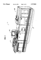
- FIG. 1 is a view depicting an electronic printing system
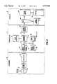
- FIG. 2 is a block diagram depicting the major elements of the printing system shown in FIG. 1;
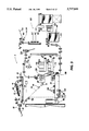
- FIG. 3 is a plan view illustrating the principal mechanical components of the printing system shown in FIG. 1;
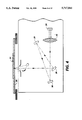
- FIG. 4 is a schematic view showing certain construction details of the document scanner for the printing system shown in FIG. 1;
- FIGS. 5A, 5B, 6 and 7 comprise schematic block diagrams showing the major parts of the control section for the printing system shown in FIG. 1;
- FIG. 8 is a block diagram of the operating system together with printed wiring boards and shared line connections for the printing system shown in FIG. 1;
- FIGS. 9-11 represent a high level flowchart of an operator selected deferred action for an inactive print job's procedure according to the present invention.
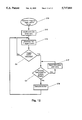
- FIG. 12 represents a high level flowchart of an alternate embodiment of the present invention.
- FIGS. 1 and 2 there is shown an exemplary laser based printing system (or imaging device) 2 for processing print jobs in accordance with the teachings of the present invention.
- Print system 2 for purposes of explanation, is divided into a scanner section 6, controller section 7, and printer section 8. While a specific printing system is shown and described, the present invention may be used with other types of printing systems such as ink jet, ionographic, etc.
- scanner section 6 incorporates a transparent surface 20 on which the document 22 to be scanned is located.
- One or more linear arrays 24 are supported for reciprocating scanning movement below platen 20.
- Lens 26 and mirrors 28, 29, 30, cooperate to focus array 24 on a line-like segment of platen 20 and the document being scanned thereon.
- Array 24 provides image signals or pixels representative of the image scanned, which after processing by processor 25, are output to controller section 7.
- Processor 25 converts the analog image signals output by array 24 to digital image signals and processes the image signals as required to enable system 2 to store and handle the image data in the form required to carry out the job program.
- Processor 25 also provides enhancements and changes to the image signals such as, for example, filtering, thresholding, screening, cropping, reduction/enlarging, sharpness, TRC control, halftone screen frequency control, etc.
- the document must be rescanned.
- Documents 22 to be scanned may be located on platen for scanning by automatic document handler (ADF) 35 operable in either a recirculating document handling (RDH) mode or a semi-automatic document handling (SADH) mode.
- ADF automatic document handler
- RH recirculating document handling
- SADH semi-automatic document handling
- a manual mode including a book mode and a computer forms feeder (CFF) mode are also provided, the latter to accommodate documents in the form of computer fanfold.
- document handler 35 has a document tray 37 in which documents 22 are arranged in stacks or batches. The documents 22 in tray 37 are advanced by vacuum feed belt 42 on the platen 20 where the document is scanned by array 24. Following scanning, the document is removed from platen 20 and returned to the document tray 37 using document transport roller nips 44.
- computer forms material is fed through slot 46 and advanced by feed rolls 49 to document feed belt 42 which, in turn, advances a page of the fanfold material into position on platen 20.
- printer section 8 comprises a laser type printer and, for purposes of explanation, is separated into a raster output scanner (ROS) section 87, Print Module Section 95, Paper Supply Section 107, and High Speed Finisher 120.
- ROS 87 has a laser 91, the beam of which is split into two imaging beams 94.
- Each beam 94 is modulated in accordance with the content of an image signal input by acousto-optic modulator 92 to provide dual imaging beams 94.
- Beams 94 are scanned across a moving photoreceptor 98 of Print Module 95 by the mirrored facets of a rotating polygon 100 to expose two image lines on photoreceptor 98 with each scan and create the latent electrostatic images represented by the image signal input to the modulator 92.
- Photoreceptor 98 is uniformly charged by corotrons 102 at a charging station preparatory to exposure by imaging beams 94.
- the latent electrostatic images are developed by developer 104 and transferred at transfer station 106 to a print media 108 delivered by Paper Supply Section 107.
- Media 108 as will appear may comprise any of the variety of sheet sizes, types and color.
- print media is brought forward and into timed registration with the developed image on photoreceptor 98 from either a main paper tray 110 or from auxiliary paper trays 112 or 114.
- the developed image transferred to the print media 108 is permanently fixed or fused by fuser 116 and the resulting prints discharged to either output tray 118, to High Speed Finisher 120 or through bypass 180 to some other downstream finishing device, which could be a low speed finishing device such as a booklet maker 200.
- High speed finisher 120 includes a stitcher 122 for stitching or stapling the prints together to form books and thermal binder 124 for adhesively binding the prints into books.
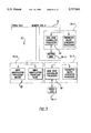
- controller section 7 for explanation purposes, divided into an image input controller 50, User Interface (UI) 52, system controller 54, main memory 56, image manipulation section 58, and image output controller 60.
- UI User Interface
- the scanned image data input from processor 25 of scanner section 6 to controller section 7 is compressed by image compressor/processor 51 of image output input controller 50 on printed wiring board (PWB) 70-3.
- image data passes through the compressor/processor 51, it is segmented into slices N scan lines wide, each slice having a slice pointer.
- the compressed image data together with slice pointers and any related image descriptors providing image specific information are placed in an image file.
- the image files, which represent different print jobs, are temporarily stored in the system memory 61, which comprises a RAM, pending transfer into main memory 56 where the data is held pending use.
- UI 52 includes a combined operator/controller CRT display consisting of an interactive touchscreen 62, keyboard 64, and mouse 66.
- UI 52 interfaces the operator with printing system 2, enabling the operator to program print jobs and other instructions, to obtain system operating information, programming information, diagnostic information, etc.
- Items displayed on touchscreen 62 such as files and icons are actuated by either touching the displayed item on screen 62 with a finger or by using mouse 66 to point a cursor to the item selected and keying the mouse.
- Main memory 56 has plural hard disks 90-1, 90-2, 90-3 for storing machine Operating System software, machine operating data, and the scanned image data currently being processed.
- main memory 56 When the compressed image data in main memory 56 requires further processing, or is required for display on touchscreen 62 of UI 52, or is required by printer section 8, the data is accessed in main memory 56. Where further processing other than that provided by processor 25 is required, the data is transferred to image manipulation section 58 on PWB 70-6 where the additional processing steps such as collation, make-ready, decomposition, etc. are carried out. Following processing, the data may be returned to main memory 56, sent to UI 52 for display on touchscreen 62, or sent to image output controller 60.
- Image data output to image output controller 60 is decompressed and ready for printing by image generating processors 86 of PWBs 70-7, 70-8 (see FIG. 5A). Following this, the data is output by dispatch processors 88, 89 on PWB 70-9 to printer section 8. Image data sent to printer section 8 for printing is normally purged from memory 56 to make room for new image data.
- control section 7 includes a plurality of Printed Wiring Boards (PWBs) 70, PWBs being coupled with one another and with System Memory 61 by a pair of memory buses 72, 74.
- Memory controller 76 couples System Memory 61 with buses 72, 74.
- PWBs include system processor PWB 70-1 having plural system processors 78; low speed I/O processor PWB 70-2 having UI communication controller 80 for transmitting data to and from UI 52; PWBs 70-3, 70-4, 70-5 having disk drive controller/processors 82 for transmitting data to and from disks 90-1, 90-2, 90-3, respectively, of main memory 56 (image compressor/processor 51 for compressing the image data is on PWB 70-3); image manipulation PWB 70-6 with image manipulation processors of image manipulation section 58; image generation processor PWBs 70-7, 70-8 with image generation processors 86 for processing the image data for printing by printing section 8; dispatch processor PWB 70-9 having dispatch processors 88, 89 for controlling transmission of data to and from printer section 8; and boot control-arbitration-scheduler PWB 70-10.
- system processor PWB 70-1 having plural system processors 78
- low speed I/O processor PWB 70-2 having UI communication controller 80 for transmitting data to and from
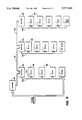
- system control signals are distributed via a plurality of printed wiring boards (PWBs). These include EDN (electronic data node) core PWB 130, Marking Imaging core PWB 132, Paper Handling core PWB 134 and Finisher Binder core PWB 136 together with various Input/Output (I/O) PWBs 138.
- a system bus 140 couples the core PWBs 130, 132, 134, 136 with each other and with controller section 7 while local buses 142 serve to couple the I/O PWBs 138 with each other and with their associated core PWB.
- the Operating System software is loaded from main memory 56 to EDN core PWB 130 and from there to remaining core PWBs 132, 134, 136 via bus 140, each core PWB 130, 132, 134, 136 having a boot ROM 147 for controlling downloading of Operating System software to PWB, fault detection, etc.
- Boot ROMs 147 also enable transmission of Operating System software and control data to and from PWBs 130, 132, 134, 136 via bus 140 and control data to and from I/O PWBs 138, via local buses 142. Additional ROM, RAM and NVM memory types are resident at various locations within system 2.
- the operator is provided with the ability to specify deferred actions that will be automatically implemented upon the occurrence of an operator selected triggering event. Therefore, the operator must, at a minimum, select both the future action and the event to trigger that future action. Additional operator selections may be required when an action requires use of additional resources and/or a retry option is specified (e.g., archive a job to a file server or upon failure of action, retry every five minutes, etc.).
- the operator When programming the trigger event, the operator will be able to specify the durability of the trigger event. In most cases, the deferred action will occur only for the first occurrence of the trigger event. However, in situations where the operator wants the deferred action to be repeated, the operator can specify that the trigger event should be reused indefinitely. Reusing a trigger event indefinitely would be a convenient method to backup critical documents to a file server once a day.
- Some of the potential future actions to be taken, as specified by the operator include, for example: display a reminder message; delete the job; copy the job to the print queue (i.e., a copy of the job also remains in memory 56); move the job to the print queue (i.e., the job is deleted from memory 56 and stored in the print queue); archive the job; perform any resource intensive task (e.g., rotate all page images in a job 90°); etc.
- triggering events can be specified by the operator. When these triggering events occur, the automatic action specified by the operator will be performed.
- triggering events include, for example: date and time (specified in relative or absolute terms); resource availability (i.e., availability of resources such as, for example, print queues, cartridge tape drives, modems, file servers, finishing devices, fonts, etc.); operator logoff; operator logon; receipt or creation of a specified second print job; system transition to a quiescent state; etc.
- the reminder function should support selection of either defined prompts or operator entered text.
- defined prompts could be used for the majority of reminder conditions such as, for example, waiting for customer print approval, waiting for shop print approval, waiting for additional job content, etc.
- the operator might, for example, enter the name and phone number of the customer contact so that such information would also be displayed or otherwise provided to the operator upon occurrence of the triggering event.
- the invention could act, for example, to automatically send a reminder mailnote to the job submitter whenever a customer action is overdue, or use remote file servers to archive or access inactive jobs.
- the invention can provide the ability to automatically call the job's contact person or department and deliver, e.g., a voice synthesized reminder when an inactive job is overdue for customer action.
- the system could be expanded to include the ability to specify multiple sequential deferred actions for inactive jobs and the ability to chain or link multiple deferred actions in a cascading and recursive fashion. Multiple sequential deferred actions may or may not be conditional on the success of the preceding action.
- One potential application for unconditional multiple sequential deferred actions includes requesting a job to print at a specified time and then to be copied to a file service; it may be desirable to file the job when the printing action ceases regardless of whether the printing action was completed.
- Another potential application is a request to file a job to one file service in its current format followed by a request to file a copy to a second file service in an alternate format.
- a conditional multiple sequential deferred action would be useful for initiating irrevocable actions contingent upon the successful completion of a preceding action. Deleting a print job only after it has been copied to a file service is an example of conditional multiple sequential deferred actions.
- the electronic reprographic system for providing an operator with a deferred action function is described with reference to FIGS. 1, 2 5A, 5B, 6 and 7.
- All inactive print jobs with their associated triggers and processing instructions are stored in the main memory 56 of the printing system 2.
- inactive print jobs may reside on a remote file server or the like.
- the operator defined triggering events and processing instruction set for the inactive print jobs upon which automatic deferred action is to be performed are entered via the User Interface (UI) 52 which, e.g., may be equipped with specialized user friendly screens that provide options for the operator to select.
- UI User Interface
- instruction set includes a single action. It can also comprise more than one action.
- the system control 54 provides automatic access of the inactive print job and associated processing instructions when a triggering event is detected by a status monitor which may be part of the system control 54.
- the status monitor may be, for example, a hardwired circuit capable of monitoring the status of all triggering event possibilities, a programmable processor or the like.
- the control 54 is also capable of providing a discriminating function to determine whether the detected triggering event is associated with or linked to any of the inactive print jobs stored in the main memory 56.
- the system control 54 and image output control 60 then process the inactive job in accordance with the specified deferred actions. If, however the inactive job is to be archived or deleted or otherwise not output, then the system control 54 performs the deferred action. The detailed operation of the system will be described below with reference to FIGS. 9-11.
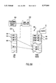
- FIG. 5B a system flow diagram illustrating inactive jobs stored in a job file and being moved to the print queue is shown in FIG. 5B.
- a triggering process output 200 is fed to a print job processor 202.
- the triggering process output 200 is the result of the triggering process sequence shown in FIGS. 10 and 11 and described below in greater detail. More specifically, the triggering process output 200 represents the outcome from the sequence of steps S6 through S12 in FIGS. 10 and 11.
- the print job processor 202 that receives the triggering process output 200 includes the system control 54 (FIG. 2) and the image output control 60. In response to the triggering process output 200, the print job processor 202 accesses a job file 155 containing a plurality of inactive print jobs 156. For the purposes of this explanation, the job file 155 is primarily stored in the main memory 56. The print job processor 202 moves or copies one or more of the inactive print jobs 156 from the job file 155 to a print queue 165 primarily stored in the system memory 61. Because the job file and print queue memory configuration is within the level of one of ordinary skill in the art, further details of such are omitted. Of course, one of ordinary skill in the art would also recognize that the main memory 56 and system memory 61 could be configured as any type of data storage facility. The printer section 8 receives the print jobs in the order specified by the print queue 165.
- Job 3 When a particular job, e.g., Job 3, is in storage with other inactive jobs in the job file 155, Job 3 is not ordered with respect to the other inactive jobs (i.e., Jobs 1, 2 and 4-N). In other words, subsequent processing operations of inactive Job 3 are initiated based on the identity of Job 3, rather than, e.g., the order of Job 3 with respect to when the other jobs were first stored in the job file 155.
- Job 3 When Job 3 is stored in the print queue 165, however, Job 3 becomes ordered with respect to the other jobs in the print queue 165. The other jobs are also ordered with respect to one another.
- Job 3 When Job 3 is in the print queue, its position is established in accordance with the print queue management rules in effect. For example, in a system operating under FIFO print queue rules, Job 3 follows the last of the other jobs already in the print queue and precedes the next job added to the print queue 165.
- U.S. Pat. No. 5,287,194 to Lobiondo discloses a distributed printing method for routing, partitioning and prioritizing print jobs already in the print queue. According to the method disclosed in this patent, the end user submits the job to the print queue when the user desires to print the job. Based on available printer resources, the priority of the last-submitted job with respect to earlier-submitted jobs and/or other factors, the system responds by printing the last-submitted job immediately at one or more locations, indicating the time that the last-submitted job will finish printing or indicating that the last-submitted job cannot be printed.
- the last-submitted job is an active job submitted to the print queue in a condition ready for printing. Even if the last-submitted job is not immediately printed, it occupies a defined position in the print queue in order with respect to the other jobs in the print queue.
- the Lobiondo method does not relate to processing inactive jobs not necessarily intended for immediate printing and activating these jobs in response to a user defined event (which may or may not be time-based) for printing.
- the option of whether to implement operator selected deferred action for an inactive print job is presented to the operator via the User Interface (UI) 52 of the electronic reprographic system 2 shown in FIG. 1.
- the UI 52 may include a touch screen, keyboard, mouse, etc. or any combination thereof for input purposes.
- the operator may, for example, enter a job option screen on the UI 52 which presents a deferred action option to the operator.
- the operator enters the required information to effectuate an automatic deferred action for an inactive print job via the UI 52.
- FIGS. 9-11 depict flowcharts showing the operation of an electronic reprographic system in accordance with the present invention.
- FIG. 9 shows the preferred implementation of operator specified deferred actions and associated trigger events in accordance with the present invention.
- the triggering event can be any one of a number of system operating conditions, such as, for example, date and time (specified in relative or absolute terms); resource availability (i.e., availability of system resources, such as, for example, print queues, cartridge tape drives, modems, file servers, finishing devices, fonts, etc.); operator logoff; operator logon; receipt or creation of a specified second print job, system transition to a quiescent state; etc.
- the operator selects the triggering event and the action to be taken S1.
- the triggering event is classified as one of a predetermined type of triggering event S2.
- the job ID, trigger parameters and action are added to the database for that class of triggering events S3.
- the inactive print job is then placed, for example, in a system job directory located in the memory 56 which holds all inactive print jobs S4 or alternatively in a remote networked file server if the system supports networked operation. No further action is required S5 once the job has been placed in the system job directory or alternatively in a remote networked file server.
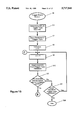
- FIGS. 10-11 show a representation of the system operation after detection of a triggering event.
- a triggering event occurs S6, such as, for example, a logoff function
- the system must then determine which trigger type is associated with the triggering event D1, such as, for example, user access control.
- D1 such as, for example, user access control
- the system accesses the appropriate database associated with the type of triggering event detected S7.
- This database is arranged such that when an operator chooses which triggering event will be used to initiate the deferred action, these deferred action sequences are stored according to an inactive job identifier in a database corresponding to the type of triggering event chosen. Therefore, in this example, a triggering event such as a logoff, will initiate a search of the User Access Control database.
- the number and types of databases are chosen by system designers based on the desired operational characteristics of the system. These can range from one database per triggering event (maximum) to one database for all triggering events (minimum). The choice depends on a variety of system efficiency parameters. For example, if the system only has one or two triggering events, having only one triggering event database may be sufficient. If, however, there are a wide variety of possible triggering events, it may be more efficient to classify the triggering events into logical categories and have a database for each category. In this example, the latter occurs.
- the trigger is a logoff function that logically resides in the User Access Control database.
- an index counter, i is initialized to zero S8.
- the counter i is then incremented by one S9.
- the record in the database corresponding to the ith position is then read S10.
- the system then enters a decisional step D2 wherein it compares the ith record parameters to the currently detected trigger parameter, for example logoff. If the ith record trigger parameters do not match the operator selected triggering event, another decisional step is entered D3. In this step, the system determines whether any more records exist in the currently accessed database D3. If there are no more records in the database, the sequence ends S20. If, however, more records do exist in the current database, steps S9 thru D3 are conducted again.
- step D4 determines whether system resources are available to carry out the desired preselected deferred actions D4. If the required resources are not currently available, the system may retry after a predetermined period of time, signal a fault to the operator or abort the deferred action entirely S11, consistent with system design for handling similar resource availability problems. If the resources are available in D4, the specified deferred action is accomplished S12. Once the deferred action for the inactive print job has been initiated, the record is checked to determine if the action has been programmed to be repeated D5. If the action is not a recurring action, then the record in the currently accessed database is removed S13 to avoid duplicative processing. In addition, the system repeats all the steps S9, S10, D2, D3, D4, S11, S12, S13 and S20 until the database has been completely and thoroughly checked for all operator selected deferred actions for the currently accessed database.
- FIG. 12 shows a flowchart of an alternate implementation of this invention.
- the operator selects the triggering event and the action to be taken S14.
- the inactive print job is then placed, for example, in a system job directory located in the memory 56 which holds all inactive print jobs or alternatively in a remote networked file server if the system supports networked operation S15.
- the electronic printing system then continually monitors system activity to detect the occurrence of an operator selected triggering event S16.
- the system continually monitors the potential triggering events during the monitoring phase S16 and the decisional phase D6. If during the decisional phase D6, a triggering event is detected, another decisional step must be entered to determine whether the services required for the deferred action are ready to implement the required action D7. For example, if an inactive job requires some action, the system must determine whether resources are available to carry out the operation required by the selected deferred action when the triggering event occurs. If the resources required to carry out the desired action are available, the system carries out the specified action S18. If, however, resources are not currently available to carry out the desired action, the system may wait for a predetermined period of time and then initiate a retry sequence S17 where the system again checks for the availability of processing resources D7. The system may also identify a failure or fault and require further operator action.
- the system will continue to monitor the status of the triggering events S16, D6 until a triggering event is detected.
- the preferred embodiment described is a device controlled by one or more digital computers, the invention could be applied using any means of logic control, including but not limited to, the following: electronic, mechanical, or fluidics control systems using digital or analog processing.
Abstract
Description
Claims (18)
Priority Applications (1)
| Application Number | Priority Date | Filing Date | Title |
|---|---|---|---|
| US08/612,648 US5717841A (en) | 1993-04-20 | 1996-03-08 | Method and apparatus for providing operator selected deferred action for inactive print jobs |
Applications Claiming Priority (2)
| Application Number | Priority Date | Filing Date | Title |
|---|---|---|---|
| US4929093A | 1993-04-20 | 1993-04-20 | |
| US08/612,648 US5717841A (en) | 1993-04-20 | 1996-03-08 | Method and apparatus for providing operator selected deferred action for inactive print jobs |
Publications (1)
| Publication Number | Publication Date |
|---|---|
| US5717841A true US5717841A (en) | 1998-02-10 |
Family
ID=21959056
Family Applications (1)
| Application Number | Title | Priority Date | Filing Date |
|---|---|---|---|
| US08/612,648 Expired - Lifetime US5717841A (en) | 1993-04-20 | 1996-03-08 | Method and apparatus for providing operator selected deferred action for inactive print jobs |
Country Status (2)
| Country | Link |
|---|---|
| US (1) | US5717841A (en) |
| JP (1) | JPH0744362A (en) |
Cited By (68)
| Publication number | Priority date | Publication date | Assignee | Title |
|---|---|---|---|---|
| US5873659A (en) * | 1996-04-24 | 1999-02-23 | Edwards; Steve Michael | Method and apparatus for providing a printer having internal queue job management |
| US6307615B1 (en) * | 1998-11-04 | 2001-10-23 | Canon Kabushiki Kaisha | Image processing apparatus, image processing method and image processing system |
| US6332170B1 (en) * | 1997-11-11 | 2001-12-18 | Minolta Co., Ltd. | Printing apparatus with job interrupt capabilities and control method thereof |
| US20010055123A1 (en) * | 2000-05-16 | 2001-12-27 | Xerox Corporation | Apparatus and method for describing, planning and automatically programming complex finishing tasks |
| US20020018235A1 (en) * | 2000-05-16 | 2002-02-14 | Xerox Corporation | Finishing module coordinator apparatus and method for assembler/finisher systems |
| US20020054203A1 (en) * | 2000-05-31 | 2002-05-09 | Keiki Yamada | Optical printing device |
| US20020085476A1 (en) * | 2000-05-19 | 2002-07-04 | Kurosh Samari-Kermani | Medical data recording system |
| GB2372127A (en) * | 2000-08-30 | 2002-08-14 | Hewlett Packard Co | Delayed printing of print jobs requiring special resources |
| US6453268B1 (en) | 1999-07-07 | 2002-09-17 | International Business Machines Corporation | Method, system, and program for monitoring a device with a computer using user selected monitoring settings |
| US6504621B1 (en) | 1998-01-28 | 2003-01-07 | Xerox Corporation | System for managing resource deficient jobs in a multifunctional printing system |
| US6519613B1 (en) * | 1997-10-01 | 2003-02-11 | International Business Machines Corporation | Non-blocking drain method and apparatus for use in processing requests on a resource |
| US6646758B1 (en) | 2000-01-31 | 2003-11-11 | Hewlett-Packard Development Company, L.P. | Methods and arrangements for improved paper handling based on printer configuration status information |
| US20030234958A1 (en) * | 2002-06-24 | 2003-12-25 | Fritz Terry-Lee M. | Printing system |
| US20040019705A1 (en) * | 2002-07-22 | 2004-01-29 | Toshiba Tec Kabushiki Kaisha | Backup and recovery system and method |
| US20040046970A1 (en) * | 2002-09-06 | 2004-03-11 | Toshiba Tec Kabushiki Kaisha | Automatic adjustment and recovery system and method |
| US20040181815A1 (en) * | 2001-11-19 | 2004-09-16 | Hull Jonathan J. | Printer with radio or television program extraction and formating |
| US20040201735A1 (en) * | 2001-04-30 | 2004-10-14 | Baron John M. | Image storage queue |
| US20040257613A1 (en) * | 2003-04-02 | 2004-12-23 | Hiroki Okabe | Print job management apparatus and print job management method |
| US20050008221A1 (en) * | 2001-11-19 | 2005-01-13 | Hull Jonathan J. | Printing system with embedded audio/video content recognition and processing |
| US6850337B1 (en) | 2000-01-31 | 2005-02-01 | Hewlett-Packard Development Company, L.P. | Methods and arrangement for providing and using printer configuration status information |
| US20050068570A1 (en) * | 2003-09-25 | 2005-03-31 | Hart Peter E. | Printer user interface |
| US20050071763A1 (en) * | 2003-09-25 | 2005-03-31 | Hart Peter E. | Stand alone multimedia printer capable of sharing media processing tasks |
| US20050071746A1 (en) * | 2003-09-25 | 2005-03-31 | Hart Peter E. | Networked printer with hardware and software interfaces for peripheral devices |
| US20050068572A1 (en) * | 2003-09-25 | 2005-03-31 | Hart Peter E. | Printer with hardware and software interfaces for media devices |
| US20050068568A1 (en) * | 2003-09-25 | 2005-03-31 | Hart Peter E. | User interface for networked printer |
| US20050068581A1 (en) * | 2003-09-25 | 2005-03-31 | Hull Jonathan J. | Printer with multimedia server |
| US20050068569A1 (en) * | 2003-09-25 | 2005-03-31 | Hull Jonathan J. | Printer with document-triggered processing |
| US20050068571A1 (en) * | 2003-09-25 | 2005-03-31 | Hart Peter E. | Stand alone multimedia printer with user interface for allocating processing |
| US20050071520A1 (en) * | 2003-09-25 | 2005-03-31 | Hull Jonathan J. | Printer with hardware and software interfaces for peripheral devices |
| US20050071519A1 (en) * | 2003-09-25 | 2005-03-31 | Hart Peter E. | Stand alone printer with hardware / software interfaces for sharing multimedia processing |
| US20050068573A1 (en) * | 2003-09-25 | 2005-03-31 | Hart Peter E. | Networked printing system having embedded functionality for printing time-based media |
| US20050068567A1 (en) * | 2003-09-25 | 2005-03-31 | Hull Jonathan J. | Printer with audio or video receiver, recorder, and real-time content-based processing logic |
| US20050231739A1 (en) * | 2004-03-30 | 2005-10-20 | Dar-Shyang Lee | Projector/printer for displaying or printing of documents |
| US20050275876A1 (en) * | 2004-06-10 | 2005-12-15 | Mclean Bruce L | Method and system for server-based management of requests such as print jobs |
| US20050280835A1 (en) * | 2004-06-17 | 2005-12-22 | Debusschere Eric T | Mouse support for a printing device |
| US7003723B1 (en) | 2000-05-17 | 2006-02-21 | Eastman Kodak Company | System and method for representing and managing pages in a production printing workflow |
| DE10205724B4 (en) * | 2001-02-12 | 2006-05-04 | Hewlett-Packard Development Co., L.P., Houston | Method and printer for active print queue management |
| US7113959B1 (en) | 2000-01-10 | 2006-09-26 | Imagex, Inc. | System and method of using human resources data to generate printed products |
| US20060227376A1 (en) * | 2005-03-29 | 2006-10-12 | Kabushiki Kaisha Toshiba | Secure image data system and method |
| US20060227377A1 (en) * | 2005-04-08 | 2006-10-12 | Konica Minolta Business Technologies, Inc. | Data outputting apparatus, and recording medium in which data outputting program is recorded |
| US20060239125A1 (en) * | 2005-04-20 | 2006-10-26 | Asustek Computer Inc. | Display system and fixed time remind method therefor |
| US20060271418A1 (en) * | 2005-05-26 | 2006-11-30 | Avaya Technology Corp. | Method for discovering problem agent behaviors |
| US20070009276A1 (en) * | 2005-07-05 | 2007-01-11 | Xerox Corporation | Method and system for improving the throughput of a high capacity document printer |
| US20070086024A1 (en) * | 2000-05-17 | 2007-04-19 | Kremer Karl H | Late binding of tab image context to ordered tab stock |
| US20070097406A1 (en) * | 2000-11-21 | 2007-05-03 | Seiko Epson Corporation | Print job management apparatus |
| US20070113164A1 (en) * | 2000-05-17 | 2007-05-17 | Hansen David R | System and method for implementing compound documents in a production printing workflow |
| US20070115495A1 (en) * | 2005-11-24 | 2007-05-24 | Fuji Xerox Co., Ltd. | Image processing apparatus, image processing system, computer readable medium, and image processing method |
| US7240334B1 (en) | 2000-06-29 | 2007-07-03 | International Business Machines Corporation | Methods, systems, and computer program products for deferred computer program tracing |
| US20070180159A1 (en) * | 2006-01-31 | 2007-08-02 | Canon Kabushiki Kaisha | Image forming apparatus and job control method |
| US20080037043A1 (en) * | 2000-11-30 | 2008-02-14 | Ricoh Co., Ltd. | Printer With Embedded Retrieval and Publishing Interface |
| US20080063368A1 (en) * | 2000-02-11 | 2008-03-13 | Datcard System, Inc. | System and Method for Producing Medical Image Data onto Portable Digital Recording Media |
| US7475251B2 (en) | 2003-08-11 | 2009-01-06 | Ricoh Co., Ltd. | Multimedia output device having embedded encryption functionality |
| US7505178B2 (en) | 2003-09-25 | 2009-03-17 | Ricoh Co., Ltd. | Semantic classification and enhancement processing of images for printing applications |
| US7511846B2 (en) | 2003-09-25 | 2009-03-31 | Ricoh Co., Ltd. | Printer having embedded functionality for printing time-based media |
| EP2051144A1 (en) | 1998-09-29 | 2009-04-22 | Canon Kabushiki Kaisha | Image forming apparatus for managing copy sheets individually |
| US7551312B1 (en) | 2005-03-17 | 2009-06-23 | Ricoh Co., Ltd. | Annotable document printer |
| US7603615B2 (en) | 2004-03-30 | 2009-10-13 | Ricoh Co., Ltd. | Multimedia projector-printer |
| US20090317121A1 (en) * | 2008-06-18 | 2009-12-24 | Konica Minolta Business Technologies, Inc. | Image forming apparatus and job execution method |
| US7747655B2 (en) | 2001-11-19 | 2010-06-29 | Ricoh Co. Ltd. | Printable representations for time-based media |
| US7818285B1 (en) | 2000-01-10 | 2010-10-19 | Fedex Office And Print Services, Inc. | System and method of using a sales management system to generate printed products |
| US7861169B2 (en) | 2001-11-19 | 2010-12-28 | Ricoh Co. Ltd. | Multimedia print driver dialog interfaces |
| US20110164275A1 (en) * | 2010-01-07 | 2011-07-07 | Canon Kabushiki Kaisha | Printing apparatus, control method for print job in the printing apparatus, and storage medium holding program |
| US8285083B2 (en) | 2006-04-26 | 2012-10-09 | Datcard Systems, Inc. | System for remotely generating and distributing DICOM-compliant media volumes |
| US8345279B1 (en) * | 2000-01-10 | 2013-01-01 | Tijemiksho Data, Llc | System for establishing event rules for sales management databases |
| US20150116754A1 (en) * | 2013-10-31 | 2015-04-30 | Ricoh Company, Ltd. | Image forming apparatus, method of deleting print request, and program |
| CN109213456A (en) * | 2017-06-30 | 2019-01-15 | 大数据奥尼尔公司 | Manage a batch facility |
| US11868918B2 (en) | 2017-06-30 | 2024-01-09 | Hand Held Products, Inc. | Managing a fleet of devices |
| US11962464B2 (en) | 2017-06-30 | 2024-04-16 | Hand Held Products, Inc. | Managing a fleet of devices |
Families Citing this family (1)
| Publication number | Priority date | Publication date | Assignee | Title |
|---|---|---|---|---|
| JP4594498B2 (en) * | 2000-07-17 | 2010-12-08 | 帝人株式会社 | Breathing gas supply device |
Citations (6)
| Publication number | Priority date | Publication date | Assignee | Title |
|---|---|---|---|---|
| US4843571A (en) * | 1985-07-01 | 1989-06-27 | Oce-Nederland B. V. | Office automation systems |
| US5133048A (en) * | 1990-09-28 | 1992-07-21 | Xerox Corporation | System for printing ordered stock |
| US5159395A (en) * | 1991-08-29 | 1992-10-27 | Xerox Corporation | Method of scheduling copy sheets in a dual mode duplex printing system |
| US5161037A (en) * | 1990-10-10 | 1992-11-03 | Fuji Xerox Corporation, Ltd. | Image processing system and method for processing documents in accordance with a job control sheet |
| US5287194A (en) * | 1992-11-25 | 1994-02-15 | Xerox Corporation | Distributed printing |
| US5563986A (en) * | 1992-04-10 | 1996-10-08 | Fuji Xerox Co., Ltd. | Image processing system |
-
1994
- 1994-04-12 JP JP6073635A patent/JPH0744362A/en active Pending
-
1996
- 1996-03-08 US US08/612,648 patent/US5717841A/en not_active Expired - Lifetime
Patent Citations (6)
| Publication number | Priority date | Publication date | Assignee | Title |
|---|---|---|---|---|
| US4843571A (en) * | 1985-07-01 | 1989-06-27 | Oce-Nederland B. V. | Office automation systems |
| US5133048A (en) * | 1990-09-28 | 1992-07-21 | Xerox Corporation | System for printing ordered stock |
| US5161037A (en) * | 1990-10-10 | 1992-11-03 | Fuji Xerox Corporation, Ltd. | Image processing system and method for processing documents in accordance with a job control sheet |
| US5159395A (en) * | 1991-08-29 | 1992-10-27 | Xerox Corporation | Method of scheduling copy sheets in a dual mode duplex printing system |
| US5563986A (en) * | 1992-04-10 | 1996-10-08 | Fuji Xerox Co., Ltd. | Image processing system |
| US5287194A (en) * | 1992-11-25 | 1994-02-15 | Xerox Corporation | Distributed printing |
Cited By (122)
| Publication number | Priority date | Publication date | Assignee | Title |
|---|---|---|---|---|
| US5873659A (en) * | 1996-04-24 | 1999-02-23 | Edwards; Steve Michael | Method and apparatus for providing a printer having internal queue job management |
| US6519613B1 (en) * | 1997-10-01 | 2003-02-11 | International Business Machines Corporation | Non-blocking drain method and apparatus for use in processing requests on a resource |
| US6332170B1 (en) * | 1997-11-11 | 2001-12-18 | Minolta Co., Ltd. | Printing apparatus with job interrupt capabilities and control method thereof |
| US6504621B1 (en) | 1998-01-28 | 2003-01-07 | Xerox Corporation | System for managing resource deficient jobs in a multifunctional printing system |
| EP2051144A1 (en) | 1998-09-29 | 2009-04-22 | Canon Kabushiki Kaisha | Image forming apparatus for managing copy sheets individually |
| US6307615B1 (en) * | 1998-11-04 | 2001-10-23 | Canon Kabushiki Kaisha | Image processing apparatus, image processing method and image processing system |
| US6453268B1 (en) | 1999-07-07 | 2002-09-17 | International Business Machines Corporation | Method, system, and program for monitoring a device with a computer using user selected monitoring settings |
| US7818285B1 (en) | 2000-01-10 | 2010-10-19 | Fedex Office And Print Services, Inc. | System and method of using a sales management system to generate printed products |
| US8345279B1 (en) * | 2000-01-10 | 2013-01-01 | Tijemiksho Data, Llc | System for establishing event rules for sales management databases |
| US7113959B1 (en) | 2000-01-10 | 2006-09-26 | Imagex, Inc. | System and method of using human resources data to generate printed products |
| US7099034B2 (en) | 2000-01-31 | 2006-08-29 | Hewlett-Packard Development Company, L.P. | Methods and arrangements for providing and using printer configuration status information |
| US6850337B1 (en) | 2000-01-31 | 2005-02-01 | Hewlett-Packard Development Company, L.P. | Methods and arrangement for providing and using printer configuration status information |
| US20050084314A1 (en) * | 2000-01-31 | 2005-04-21 | Anderson James E. | Methods and arrangements for providing and using printer configuration status information |
| US6646758B1 (en) | 2000-01-31 | 2003-11-11 | Hewlett-Packard Development Company, L.P. | Methods and arrangements for improved paper handling based on printer configuration status information |
| US20090248750A1 (en) * | 2000-02-11 | 2009-10-01 | Datcard Systems, Inc. | System and method for producing medical image data onto portable digital recording media |
| US7783163B2 (en) | 2000-02-11 | 2010-08-24 | Datcard Systems, Inc. | System and method for producing medical image data onto portable digital recording media |
| US20080063368A1 (en) * | 2000-02-11 | 2008-03-13 | Datcard System, Inc. | System and Method for Producing Medical Image Data onto Portable Digital Recording Media |
| US10248760B2 (en) | 2000-02-11 | 2019-04-02 | Datcard Systems, Inc. | System and method for producing medical image data onto portable digital recording media |
| US20090245754A1 (en) * | 2000-02-11 | 2009-10-01 | Datcard Systems, Inc. | System and method for producing medical image data onto portable digital recording media |
| US8515251B2 (en) | 2000-02-11 | 2013-08-20 | Datcard Systems, Inc. | System and method for producing medical image data onto portable digital recording media |
| US8509604B2 (en) | 2000-02-11 | 2013-08-13 | Datcard Systems, Inc. | System and method for producing medical image data onto portable digital recording media |
| US8483550B2 (en) | 2000-02-11 | 2013-07-09 | Datcard Systems, Inc. | System and method for producing medical image data onto portable digital recording media |
| US20090252480A1 (en) * | 2000-02-11 | 2009-10-08 | Datcard Systems, Inc. | System and method for producing medical image data onto portable digital recording media |
| US20090252479A1 (en) * | 2000-02-11 | 2009-10-08 | Datcard Systems, Inc. | System and method for producing medical image data onto portable digital recording media |
| US7729597B2 (en) | 2000-02-11 | 2010-06-01 | Datcard Systems, Inc. | System and method for producing medical image data onto portable digital recording media |
| US7734157B2 (en) | 2000-02-11 | 2010-06-08 | Datcard Systems, Inc. | System and method for producing medical image data onto portable digital recording media |
| US7783174B2 (en) | 2000-02-11 | 2010-08-24 | Datcard Systems, Inc. | System and method for producing medical image data onto portable digital recording media |
| US7061636B2 (en) | 2000-05-16 | 2006-06-13 | Xerox Corporation | Production monitor controller apparatus and method for assembler/finisher systems |
| US20020018235A1 (en) * | 2000-05-16 | 2002-02-14 | Xerox Corporation | Finishing module coordinator apparatus and method for assembler/finisher systems |
| US7206087B2 (en) | 2000-05-16 | 2007-04-17 | Xerox Corporation | Finishing module coordinator apparatus and method for assembler/finisher systems |
| US20020097407A1 (en) * | 2000-05-16 | 2002-07-25 | Xerox Corporation | Production monitor controller apparatus and method for assembler/finisher systems |
| US20010055123A1 (en) * | 2000-05-16 | 2001-12-27 | Xerox Corporation | Apparatus and method for describing, planning and automatically programming complex finishing tasks |
| US20020016803A1 (en) * | 2000-05-16 | 2002-02-07 | Xerox Corporation | Graphic user interface for managing assembler/finisher systems |
| US7003723B1 (en) | 2000-05-17 | 2006-02-21 | Eastman Kodak Company | System and method for representing and managing pages in a production printing workflow |
| US8386945B1 (en) | 2000-05-17 | 2013-02-26 | Eastman Kodak Company | System and method for implementing compound documents in a production printing workflow |
| US20070086024A1 (en) * | 2000-05-17 | 2007-04-19 | Kremer Karl H | Late binding of tab image context to ordered tab stock |
| US20070113164A1 (en) * | 2000-05-17 | 2007-05-17 | Hansen David R | System and method for implementing compound documents in a production printing workflow |
| US20090034404A1 (en) * | 2000-05-19 | 2009-02-05 | Cyrus Kurosh Samari | Medical Data Recording Method |
| US20150006191A1 (en) * | 2000-05-19 | 2015-01-01 | Sorna Corporation | Medical data recording system |
| US7965408B2 (en) * | 2000-05-19 | 2011-06-21 | Cyrus Kurosh Samari | Medical data recording system |
| US8045214B2 (en) | 2000-05-19 | 2011-10-25 | Sorna Corporation | Medical data recording apparatus |
| US20020085476A1 (en) * | 2000-05-19 | 2002-07-04 | Kurosh Samari-Kermani | Medical data recording system |
| US8059304B2 (en) | 2000-05-19 | 2011-11-15 | Sorna Corporation | Medical data recording system |
| US8687226B2 (en) * | 2000-05-19 | 2014-04-01 | Sorna Corporation | Medical data recording system |
| US20120116808A1 (en) * | 2000-05-19 | 2012-05-10 | Sorna Corporation | Medical data recording system |
| US20090059772A1 (en) * | 2000-05-19 | 2009-03-05 | Cyrus Kurosh Samari | Medical Data Recording System |
| US10268801B2 (en) * | 2000-05-19 | 2019-04-23 | Sorna Corporation | Medical data recording system |
| US20020054203A1 (en) * | 2000-05-31 | 2002-05-09 | Keiki Yamada | Optical printing device |
| US7240334B1 (en) | 2000-06-29 | 2007-07-03 | International Business Machines Corporation | Methods, systems, and computer program products for deferred computer program tracing |
| GB2372127A (en) * | 2000-08-30 | 2002-08-14 | Hewlett Packard Co | Delayed printing of print jobs requiring special resources |
| GB2372127B (en) * | 2000-08-30 | 2004-05-26 | Hewlett Packard Co | Delayed printing of print jobs requiring special resources |
| US6873425B1 (en) | 2000-08-30 | 2005-03-29 | Hewlett-Packard Development Company, L.P. | Delayed printing of print jobs requiring special resources |
| US20070097406A1 (en) * | 2000-11-21 | 2007-05-03 | Seiko Epson Corporation | Print job management apparatus |
| US20080037043A1 (en) * | 2000-11-30 | 2008-02-14 | Ricoh Co., Ltd. | Printer With Embedded Retrieval and Publishing Interface |
| US7573604B2 (en) | 2000-11-30 | 2009-08-11 | Ricoh Co., Ltd. | Printer with embedded retrieval and publishing interface |
| US20090238540A1 (en) * | 2001-01-17 | 2009-09-24 | Datcard Systems, Inc. | System and method for producing medical image data onto portable digital recording media |
| US7801422B2 (en) | 2001-01-17 | 2010-09-21 | Datcard Systems, Inc. | System and method for producing medical image data onto portable digital recording media |
| DE10205724B4 (en) * | 2001-02-12 | 2006-05-04 | Hewlett-Packard Development Co., L.P., Houston | Method and printer for active print queue management |
| US7116361B2 (en) * | 2001-04-30 | 2006-10-03 | Hewlett-Packard Development Company | Image storage queue adapted to store images according to archival status |
| US20040201735A1 (en) * | 2001-04-30 | 2004-10-14 | Baron John M. | Image storage queue |
| US20050008221A1 (en) * | 2001-11-19 | 2005-01-13 | Hull Jonathan J. | Printing system with embedded audio/video content recognition and processing |
| US7424129B2 (en) | 2001-11-19 | 2008-09-09 | Ricoh Company, Ltd | Printing system with embedded audio/video content recognition and processing |
| US20040181815A1 (en) * | 2001-11-19 | 2004-09-16 | Hull Jonathan J. | Printer with radio or television program extraction and formating |
| US7861169B2 (en) | 2001-11-19 | 2010-12-28 | Ricoh Co. Ltd. | Multimedia print driver dialog interfaces |
| US7747655B2 (en) | 2001-11-19 | 2010-06-29 | Ricoh Co. Ltd. | Printable representations for time-based media |
| US20030234958A1 (en) * | 2002-06-24 | 2003-12-25 | Fritz Terry-Lee M. | Printing system |
| US8103794B2 (en) * | 2002-07-22 | 2012-01-24 | Kabushiki Kaisha Toshiba | Backup and recovery system and method |
| US20040019705A1 (en) * | 2002-07-22 | 2004-01-29 | Toshiba Tec Kabushiki Kaisha | Backup and recovery system and method |
| US20040046970A1 (en) * | 2002-09-06 | 2004-03-11 | Toshiba Tec Kabushiki Kaisha | Automatic adjustment and recovery system and method |
| US20040257613A1 (en) * | 2003-04-02 | 2004-12-23 | Hiroki Okabe | Print job management apparatus and print job management method |
| US7612921B2 (en) * | 2003-04-02 | 2009-11-03 | Seiko Epson Corporation | Print job management apparatus and print job management method |
| US7475251B2 (en) | 2003-08-11 | 2009-01-06 | Ricoh Co., Ltd. | Multimedia output device having embedded encryption functionality |
| US20050071519A1 (en) * | 2003-09-25 | 2005-03-31 | Hart Peter E. | Stand alone printer with hardware / software interfaces for sharing multimedia processing |
| US20050071746A1 (en) * | 2003-09-25 | 2005-03-31 | Hart Peter E. | Networked printer with hardware and software interfaces for peripheral devices |
| US7440126B2 (en) | 2003-09-25 | 2008-10-21 | Ricoh Co., Ltd | Printer with document-triggered processing |
| US7570380B2 (en) | 2003-09-25 | 2009-08-04 | Ricoh Company, Ltd. | Printer user interface |
| US7573593B2 (en) | 2003-09-25 | 2009-08-11 | Ricoh Company, Ltd. | Printer with hardware and software interfaces for media devices |
| US7528977B2 (en) | 2003-09-25 | 2009-05-05 | Ricoh Co., Ltd. | Printer with hardware and software interfaces for peripheral devices |
| US20090092322A1 (en) * | 2003-09-25 | 2009-04-09 | Berna Erol | Semantic Classification and Enhancement Processing of Images for Printing Applications |
| US20050068570A1 (en) * | 2003-09-25 | 2005-03-31 | Hart Peter E. | Printer user interface |
| US8373905B2 (en) | 2003-09-25 | 2013-02-12 | Ricoh Co., Ltd. | Semantic classification and enhancement processing of images for printing applications |
| US20050071763A1 (en) * | 2003-09-25 | 2005-03-31 | Hart Peter E. | Stand alone multimedia printer capable of sharing media processing tasks |
| US20050068567A1 (en) * | 2003-09-25 | 2005-03-31 | Hull Jonathan J. | Printer with audio or video receiver, recorder, and real-time content-based processing logic |
| US8077341B2 (en) * | 2003-09-25 | 2011-12-13 | Ricoh Co., Ltd. | Printer with audio or video receiver, recorder, and real-time content-based processing logic |
| US7511846B2 (en) | 2003-09-25 | 2009-03-31 | Ricoh Co., Ltd. | Printer having embedded functionality for printing time-based media |
| US7528976B2 (en) | 2003-09-25 | 2009-05-05 | Ricoh Co., Ltd. | Stand alone printer with hardware/software interfaces for sharing multimedia processing |
| US20050068573A1 (en) * | 2003-09-25 | 2005-03-31 | Hart Peter E. | Networked printing system having embedded functionality for printing time-based media |
| US20050068572A1 (en) * | 2003-09-25 | 2005-03-31 | Hart Peter E. | Printer with hardware and software interfaces for media devices |
| US7508535B2 (en) | 2003-09-25 | 2009-03-24 | Ricoh Co., Ltd. | Stand alone multimedia printer with user interface for allocating processing |
| US20050071520A1 (en) * | 2003-09-25 | 2005-03-31 | Hull Jonathan J. | Printer with hardware and software interfaces for peripheral devices |
| US20050068571A1 (en) * | 2003-09-25 | 2005-03-31 | Hart Peter E. | Stand alone multimedia printer with user interface for allocating processing |
| US7505163B2 (en) | 2003-09-25 | 2009-03-17 | Ricoh Co., Ltd. | User interface for networked printer |
| US20050068569A1 (en) * | 2003-09-25 | 2005-03-31 | Hull Jonathan J. | Printer with document-triggered processing |
| US7505178B2 (en) | 2003-09-25 | 2009-03-17 | Ricoh Co., Ltd. | Semantic classification and enhancement processing of images for printing applications |
| US7864352B2 (en) | 2003-09-25 | 2011-01-04 | Ricoh Co. Ltd. | Printer with multimedia server |
| US20050068568A1 (en) * | 2003-09-25 | 2005-03-31 | Hart Peter E. | User interface for networked printer |
| US20050068581A1 (en) * | 2003-09-25 | 2005-03-31 | Hull Jonathan J. | Printer with multimedia server |
| US8274666B2 (en) | 2004-03-30 | 2012-09-25 | Ricoh Co., Ltd. | Projector/printer for displaying or printing of documents |
| US20050231739A1 (en) * | 2004-03-30 | 2005-10-20 | Dar-Shyang Lee | Projector/printer for displaying or printing of documents |
| US7603615B2 (en) | 2004-03-30 | 2009-10-13 | Ricoh Co., Ltd. | Multimedia projector-printer |
| US20050275876A1 (en) * | 2004-06-10 | 2005-12-15 | Mclean Bruce L | Method and system for server-based management of requests such as print jobs |
| US20050280835A1 (en) * | 2004-06-17 | 2005-12-22 | Debusschere Eric T | Mouse support for a printing device |
| US7551312B1 (en) | 2005-03-17 | 2009-06-23 | Ricoh Co., Ltd. | Annotable document printer |
| US20060227376A1 (en) * | 2005-03-29 | 2006-10-12 | Kabushiki Kaisha Toshiba | Secure image data system and method |
| US8081330B2 (en) * | 2005-04-08 | 2011-12-20 | Konica Minolta Business Technologies, Inc. | Data outputting apparatus, and recording medium in which data outputting program is recorded |
| US20060227377A1 (en) * | 2005-04-08 | 2006-10-12 | Konica Minolta Business Technologies, Inc. | Data outputting apparatus, and recording medium in which data outputting program is recorded |
| US20060239125A1 (en) * | 2005-04-20 | 2006-10-26 | Asustek Computer Inc. | Display system and fixed time remind method therefor |
| US20060271418A1 (en) * | 2005-05-26 | 2006-11-30 | Avaya Technology Corp. | Method for discovering problem agent behaviors |
| US7218876B2 (en) | 2005-07-05 | 2007-05-15 | Xerox Corporation | Method and system for improving the throughput of a high capacity document printer |
| US20070009276A1 (en) * | 2005-07-05 | 2007-01-11 | Xerox Corporation | Method and system for improving the throughput of a high capacity document printer |
| US20070115495A1 (en) * | 2005-11-24 | 2007-05-24 | Fuji Xerox Co., Ltd. | Image processing apparatus, image processing system, computer readable medium, and image processing method |
| US7965400B2 (en) * | 2005-11-24 | 2011-06-21 | Fuji Xerox Co., Ltd. | Image processing apparatus, image processing system, computer readable medium, and image processing method |
| US20070180159A1 (en) * | 2006-01-31 | 2007-08-02 | Canon Kabushiki Kaisha | Image forming apparatus and job control method |
| US8285083B2 (en) | 2006-04-26 | 2012-10-09 | Datcard Systems, Inc. | System for remotely generating and distributing DICOM-compliant media volumes |
| US20090317121A1 (en) * | 2008-06-18 | 2009-12-24 | Konica Minolta Business Technologies, Inc. | Image forming apparatus and job execution method |
| US8208828B2 (en) * | 2008-06-18 | 2012-06-26 | Konica Minolta Business Technologies, Inc. | Image forming apparatus and job execution method |
| US20110164275A1 (en) * | 2010-01-07 | 2011-07-07 | Canon Kabushiki Kaisha | Printing apparatus, control method for print job in the printing apparatus, and storage medium holding program |
| US20150116754A1 (en) * | 2013-10-31 | 2015-04-30 | Ricoh Company, Ltd. | Image forming apparatus, method of deleting print request, and program |
| CN109213456A (en) * | 2017-06-30 | 2019-01-15 | 大数据奥尼尔公司 | Manage a batch facility |
| US11868918B2 (en) | 2017-06-30 | 2024-01-09 | Hand Held Products, Inc. | Managing a fleet of devices |
| CN109213456B (en) * | 2017-06-30 | 2024-03-19 | 手持产品公司 | Managing a batch of devices |
| US11962464B2 (en) | 2017-06-30 | 2024-04-16 | Hand Held Products, Inc. | Managing a fleet of devices |
Also Published As
| Publication number | Publication date |
|---|---|
| JPH0744362A (en) | 1995-02-14 |
Similar Documents
| Publication | Publication Date | Title |
|---|---|---|
| US5717841A (en) | Method and apparatus for providing operator selected deferred action for inactive print jobs | |
| US5206735A (en) | Job interrupt for electronic copying/printing machines | |
| US5170340A (en) | System state controller for electronic image processing systems | |
| CA2048578C (en) | Control for electronic image processing systems | |
| EP0465166B1 (en) | Job/page proofing for electronic printers | |
| US5081595A (en) | Paper supply tray status in electronic printers | |
| US5467449A (en) | Fault clearance and recovery in an electronic reprographic system | |
| EP0478970B1 (en) | An electronic printing process for printing multiple up images | |
| US5229814A (en) | System for identifying a substitute paper stock for unavailable paper stock when printing a job | |
| US5148286A (en) | Method and apparatus for operating an electronic reprographic printing system upon scan interruption | |
| US5517316A (en) | Apparatus and method for saving/storing job run information generated by processing a job on a printing machine | |
| US5305056A (en) | Method of controlling diagnostics in a printing system | |
| JPH06297781A (en) | Job printing method | |
| US7679777B2 (en) | Job supplement for electronic printing machines | |
| US5179410A (en) | Printer dynamic job recovery in an electronic reprographic printing system | |
| US5170397A (en) | Method and apparatus for recovering from object faults in an electronic reprographic printing system | |
| EP0461920B1 (en) | Printing systems | |
| US5175735A (en) | Method and apparatus for handling object faults in an electronic reprographic printing system | |
| US5208814A (en) | Method and apparatus for operating an electronic reprographic printing system containing a job submit counter | |
| US5384633A (en) | Copy waiting machine interrupt slot mode | |
| EP0465179B2 (en) | Electronic copying/printing machines | |
| JPH04299654A (en) | Data backup system |
Legal Events
| Date | Code | Title | Description |
|---|---|---|---|
| AS | Assignment |
Owner name: XEROX CORPORATION, CONNECTICUT Free format text: ASSIGNMENT OF ASSIGNORS INTEREST;ASSIGNORS:FARRELL, MICHAEL E.;HUBE, RANDALL R.;GAURONSKI, JOHN F.;REEL/FRAME:008121/0016;SIGNING DATES FROM 19960329 TO 19960331 |
|
| STCF | Information on status: patent grant |
Free format text: PATENTED CASE |
|
| CC | Certificate of correction | ||
| FPAY | Fee payment |
Year of fee payment: 4 |
|
| AS | Assignment |
Owner name: BANK ONE, NA, AS ADMINISTRATIVE AGENT, ILLINOIS Free format text: SECURITY INTEREST;ASSIGNOR:XEROX CORPORATION;REEL/FRAME:013153/0001 Effective date: 20020621 |
|
| AS | Assignment |
Owner name: JPMORGAN CHASE BANK, AS COLLATERAL AGENT, TEXAS Free format text: SECURITY AGREEMENT;ASSIGNOR:XEROX CORPORATION;REEL/FRAME:015134/0476 Effective date: 20030625 Owner name: JPMORGAN CHASE BANK, AS COLLATERAL AGENT,TEXAS Free format text: SECURITY AGREEMENT;ASSIGNOR:XEROX CORPORATION;REEL/FRAME:015134/0476 Effective date: 20030625 |
|
| FPAY | Fee payment |
Year of fee payment: 8 |
|
| FPAY | Fee payment |
Year of fee payment: 12 |
|
| AS | Assignment |
Owner name: XEROX CORPORATION, CONNECTICUT Free format text: RELEASE BY SECURED PARTY;ASSIGNOR:JPMORGAN CHASE BANK, N.A. AS SUCCESSOR-IN-INTEREST ADMINISTRATIVE AGENT AND COLLATERAL AGENT TO JPMORGAN CHASE BANK;REEL/FRAME:066728/0193 Effective date: 20220822 |