US5729009A - Method for generating quasi-sinusoidal signals - Google Patents
Method for generating quasi-sinusoidal signals Download PDFInfo
- Publication number
- US5729009A US5729009A US08/478,191 US47819195A US5729009A US 5729009 A US5729009 A US 5729009A US 47819195 A US47819195 A US 47819195A US 5729009 A US5729009 A US 5729009A
- Authority
- US
- United States
- Prior art keywords
- signal
- detector array
- spatial frequency
- signals
- sinusoidal
- Prior art date
- Legal status (The legal status is an assumption and is not a legal conclusion. Google has not performed a legal analysis and makes no representation as to the accuracy of the status listed.)
- Expired - Fee Related
Links
Images


Classifications
-
- G—PHYSICS
- G06—COMPUTING; CALCULATING OR COUNTING
- G06F—ELECTRIC DIGITAL DATA PROCESSING
- G06F3/00—Input arrangements for transferring data to be processed into a form capable of being handled by the computer; Output arrangements for transferring data from processing unit to output unit, e.g. interface arrangements
- G06F3/01—Input arrangements or combined input and output arrangements for interaction between user and computer
- G06F3/03—Arrangements for converting the position or the displacement of a member into a coded form
- G06F3/0304—Detection arrangements using opto-electronic means
- G06F3/0317—Detection arrangements using opto-electronic means in co-operation with a patterned surface, e.g. absolute position or relative movement detection for an optical mouse or pen positioned with respect to a coded surface
-
- G—PHYSICS
- G06—COMPUTING; CALCULATING OR COUNTING
- G06F—ELECTRIC DIGITAL DATA PROCESSING
- G06F3/00—Input arrangements for transferring data to be processed into a form capable of being handled by the computer; Output arrangements for transferring data from processing unit to output unit, e.g. interface arrangements
- G06F3/01—Input arrangements or combined input and output arrangements for interaction between user and computer
- G06F3/03—Arrangements for converting the position or the displacement of a member into a coded form
- G06F3/0304—Detection arrangements using opto-electronic means
- G06F3/0312—Detection arrangements using opto-electronic means for tracking the rotation of a spherical or circular member, e.g. optical rotary encoders used in mice or trackballs using a tracking ball or in mouse scroll wheels
-
- G—PHYSICS
- G06—COMPUTING; CALCULATING OR COUNTING
- G06F—ELECTRIC DIGITAL DATA PROCESSING
- G06F3/00—Input arrangements for transferring data to be processed into a form capable of being handled by the computer; Output arrangements for transferring data from processing unit to output unit, e.g. interface arrangements
- G06F3/01—Input arrangements or combined input and output arrangements for interaction between user and computer
- G06F3/03—Arrangements for converting the position or the displacement of a member into a coded form
- G06F3/033—Pointing devices displaced or positioned by the user, e.g. mice, trackballs, pens or joysticks; Accessories therefor
- G06F3/0354—Pointing devices displaced or positioned by the user, e.g. mice, trackballs, pens or joysticks; Accessories therefor with detection of 2D relative movements between the device, or an operating part thereof, and a plane or surface, e.g. 2D mice, trackballs, pens or pucks
- G06F3/03543—Mice or pucks
-
- G—PHYSICS
- G06—COMPUTING; CALCULATING OR COUNTING
- G06F—ELECTRIC DIGITAL DATA PROCESSING
- G06F3/00—Input arrangements for transferring data to be processed into a form capable of being handled by the computer; Output arrangements for transferring data from processing unit to output unit, e.g. interface arrangements
- G06F3/01—Input arrangements or combined input and output arrangements for interaction between user and computer
- G06F3/03—Arrangements for converting the position or the displacement of a member into a coded form
- G06F3/033—Pointing devices displaced or positioned by the user, e.g. mice, trackballs, pens or joysticks; Accessories therefor
- G06F3/0354—Pointing devices displaced or positioned by the user, e.g. mice, trackballs, pens or joysticks; Accessories therefor with detection of 2D relative movements between the device, or an operating part thereof, and a plane or surface, e.g. 2D mice, trackballs, pens or pucks
- G06F3/03547—Touch pads, in which fingers can move on a surface
-
- G—PHYSICS
- G06—COMPUTING; CALCULATING OR COUNTING
- G06F—ELECTRIC DIGITAL DATA PROCESSING
- G06F3/00—Input arrangements for transferring data to be processed into a form capable of being handled by the computer; Output arrangements for transferring data from processing unit to output unit, e.g. interface arrangements
- G06F3/01—Input arrangements or combined input and output arrangements for interaction between user and computer
- G06F3/03—Arrangements for converting the position or the displacement of a member into a coded form
- G06F3/033—Pointing devices displaced or positioned by the user, e.g. mice, trackballs, pens or joysticks; Accessories therefor
- G06F3/0354—Pointing devices displaced or positioned by the user, e.g. mice, trackballs, pens or joysticks; Accessories therefor with detection of 2D relative movements between the device, or an operating part thereof, and a plane or surface, e.g. 2D mice, trackballs, pens or pucks
- G06F3/03549—Trackballs
-
- G—PHYSICS
- G06—COMPUTING; CALCULATING OR COUNTING
- G06F—ELECTRIC DIGITAL DATA PROCESSING
- G06F3/00—Input arrangements for transferring data to be processed into a form capable of being handled by the computer; Output arrangements for transferring data from processing unit to output unit, e.g. interface arrangements
- G06F3/01—Input arrangements or combined input and output arrangements for interaction between user and computer
- G06F3/03—Arrangements for converting the position or the displacement of a member into a coded form
- G06F3/033—Pointing devices displaced or positioned by the user, e.g. mice, trackballs, pens or joysticks; Accessories therefor
- G06F3/038—Control and interface arrangements therefor, e.g. drivers or device-embedded control circuitry
- G06F3/0383—Signal control means within the pointing device
Definitions
- the present invention relates to optical pointing devices for use with personal computers, workstations and other computing devices, and more particularly relates to optical pointing devices having no mechanically moving parts and which operate without the need for a specially patterned surface.
- Pointing devices such as mice and trackballs
- Such pointing devices allow rapid relocation of the cursor on a display screen, and are useful in many text, database and graphical programs.
- Perhaps the most common form of pointing device is the electronic mouse; the second most common may well be the trackball.
- the user controls the cursor by moving the mouse over a reference surface; the cursor moves a direction and distance proportional to the movement of the mouse.
- some electronic mice use reflectance of light over a reference pad, and others use a mechanical approach
- most prior art mice use a ball which is on the underside of the mouse and rolls over the reference surface (such as a desktop) when the mouse is moved.
- the ball contacts a pair of shaft encoders and the rotation of the ball rotates the shaft encoders, which historically includes an encoding wheel having a plurality of slits therein.
- a light source often an LED
- a photosensor such as a phototransistor
- Rotation of the encoding wheel therebetween causes a series of light pulses to be received by the photosensor, by which the rotational movement of the ball can be converted to a digital representation useable to move the cursor.
- the first such approach employs illumination of the surface with two light sources and using a single detector; the second includes illumination with only a single beam but using a grating filter in front of a single detector.
- forward and backward movement cannot be distinguished, in what is referred to as sign ambiguity.
- the detection is sensitive to one direction of movement in the plane.
- the two illuminating beams have to be rotated to be sensitive to another direction of movement; that is, for each direction of movement an independent detection system of illuminating beams and detector has to be used.
- the grating filter in front of the detector has to be rotated to be sensitive to another direction of movement.
- the present invention overcomes substantially all of the foregoing limitations of the prior art, and provides an improved method and apparatus for optical detection of motion of a detector relative to an irregularly speckled or patterned surface, such as the surface of a common office desk.
- the desk surface has no special characteristics except that it produces a sufficient amount of diffusely scattered light in response to coherent illumination.
- coherent light for example a laser diode
- the illuminated surface has a granular appearance which appears essentially as randomly distributed light and dark speckles.
- a specially configured detector is combined with novel signal processing techniques to decode bidirectional movement of the speckle pattern.
- the specially configured detector of the present invention can be combined with a printed pattern on a pad or ball in order to generate the speckles or dots without the requirement for a coherent light source--i.e., a simple diode could be used.
- the detection system of the present invention produces sinusoidal signals in quadrature for forward-backward detection using specially configured photodetectors.
- the detection system is sensitive to different directions of movement by the use of differently oriented detectors which use the same coherent illumination of the surface.
- a first significant aspect of the invention is a quadruple comb array of photodetectors which senses a component (either x or y) of the movement and produces quasi-sinusoidal quadrature signals.
- the sinusoidal properties of the signals produced by the photodectors are obtained through optical matching by which the optical system is matched to the period of the photodetector array. Movement of the detector relative to the surface is then detected by a bi-directional counter in a manner similar to a rotational encoder. By combining a plurality of such quadrature encoders at different angles, motion in both the x and y directions can be detected.
- a microprocessor can be used to combine the signals from the various detectors.
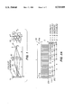
- FIG. 1 shows in simplified form an optical system according to the present invention.
- FIG. 2A shows a comb photodetector design according to the present invention.
- FIG. 2B shows a plot of spatial frequency versus spectral power for the comb photodetector of FIG. 2A.
- FIG. 3A shows in simplified schematic block diagram form the use of the comb photodetector of FIG. 2A as a detector for sensing motion in one dimension.
- FIG. 3B shows a typical waveform produced at each of the summing points of the circuit of FIG. 3A.
- FIG. 3C shows a quadrature encoder suitable for use with the circuit of FIG. 3A.
- FIG. 4 shows in simplified schematic block diagram form the use of two comb photodetectors in a detector system to detect motion in two dimensions.
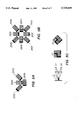
- FIGS. 5A-5C shows alternative arrangements of photodetectors, including one in which multiple images of the same spot are detected.
- FIG. 6 shows in schematic block diagram form the use of four comb photodetectors for improved detection of motion in two dimensions.
- FIGS. 7A and 7B show in flow diagram form the operation of a mouse in accordance with the present invention.
- a coherent light source 10 such as a laser diode or similar device, illuminates a surface 15 with coherent light.
- the surface which may be the surface of a desk or a piece of conventional paper diffusely scatters light, some of which passes through an aperture D and thence through a lens 20.
- the light is focused by the lens 20 onto a sensor 25, where a speckled image 30 is formed.
- the image 30 comprises a series of spots on a contrasting background, such as dark spots on a light background, essentially of the same type as described in U.S. patent application Ser. No. 08/424,125, noted above.
- the distance from the surface 15 to the lens 20 is indicated by the dimension "a”, while the distance from the lens to the detector 25 is indicated by the dimension "b".
- the average speckle size "s" is determined by the wavelength ⁇ , the lens aperture D and the image distance "b” through the relation s ⁇ b/D. More particularly, in an exemplary embodiment the value of "a” varies between 5 mm to 20 mm, while the value of "b” varies between 5 mm and 20 mm, the value of D varies between 0.2 mm and 2 mm, while the value of "s” varies between 10 ⁇ m and 100 ⁇ m and the value of ⁇ varies between 600 nm and 990 nm.
- a coherent light source is not required, and a patterned or speckled surface is used to create the speckled image 30 on the sensor 25.
- the sensor 25 is described in greater detail in FIG. 2A.
- the comb photodetector 50 comprises an array of photodetector elements 55A-55n arranged so that the output of every fourth element is connected together, forming what is essentially a quadruple array.
- the array may have an overall length L, a height S, and a distance ⁇ from the first to the fourth element, essentially forming the period of the array.
- typical values of ⁇ vary between 20 ⁇ m and 100 ⁇ m, while the value of L varies between 0.2 mm and 5 mm, and the value of S varies between 0.1 mm and 1 mm.
- the output 60 of the first group of elements may be represented as A+B sin(2 ⁇ x/ ⁇ ), while the output 65 of the second group can be represented as A+B cos(2 ⁇ x/ ⁇ ), while the output 70 of the third group can be represented as A-B sin(2 ⁇ x/ ⁇ ), and the output 75 of the fourth group can be represented as A-B cos(2 ⁇ x/ ⁇ ).
- the spectral and statistical properties of the detector signal depend on the size "s" of the speckles compared with the geometrical dimensions of the detector array.
- the power spectrum of the spatial distribution of the intensity in the speckle pattern is given by the autocorrelation function of the lens aperture D, which is shown in FIG. 2B for a circular aperture, and the image distance "b". The correlation is lost for movements in both the x and y directions when an entirely new set of speckles appears within the detector area.
- the operation of the array 50 to generate quasi-quadrature signals may be better appreciated from FIG. 3A.
- the array 50 is again shown as having four current outputs as in FIG. 2A.
- the first output 60 is shown connected to the positive input of a current summing circuit 80
- the third output 70 is shown connected to the inverting or negative input to the summing circuit 80.
- the second output 65 is connected to the positive input of a current summing circuit 85
- the fourth output 75 is connected to the negative or inverting input to the summing circuit 85.
- the output 90 of summing circuit 80 is provided to a current comparator 95, while the output 100 of the summing circuit 85 is provided to a current comparator 105.
- the current comparators 95 and 105 each have a symmetrical hysteresis around zero and a voltage output of 0 V or 5 V.
- the output of the comparator 95 is the in-phase signal P, while the output of the comparator 105 is the quadrature signal Q.
- the signals 90 and 100 represent the differential current outputs of the various phases of the detector array 50.
- the current is the response of the sensor to the optically filtered speckle pattern.
- a sinewave-like signal is generated at a temporal frequency (in hertz) of v/ ⁇ .
- a characteristic waveform is shown in FIG. 3B.
- an estimate of the displacement may be obtained by counting the number of periods the signal achieves during displacement.
- the quasi-sinewave nature of the signal shown in FIG. 3B is due to the optical matching discussed above which reduces the number of frequency lines to a single line.
- the width or height S of the detector array 50 is chosen so that the correlation of the sinusoidal signal is not reduced too much by a transverse displacement component; i.e., typically S/L ⁇ 0.1.
- the size of the illuminated spot on the surface 15 is chosen so that its image corresponds best to the detector array size in the image.
- the purpose of the comparators 95 and 105 is to generate digital signals from the sinewave-like signals shown in FIG. 3B, which facilitates interfacing the output signals P and Q to digital counters for measurement of period count.
- the phase and quadrature signals (P and Q) may be combined, as shown in FIG. 3C. More specifically, the signal P is provided to the input of a first Schmitt trigger 125 and also to one input of a NAND gate 130. The signal Q is provided to the input of a second Schmitt trigger 135 and also to one input of a NAND gate 140. The output of the Schmitt trigger 125 provides the second input to the NAND gate 140 and also provides a first input to another NAND gate 145.
- the output of the Schmitt trigger 135 provides the second input to the NAND gate 130 and also provides the second input to the NAND gate 145.
- the output of the NAND gate 145 provides the input to a third Schmitt trigger 150, the output of which is a COUNT signal.
- the output of the NAND gate 130 provides an inverted CLEAR signal to a D flipflop 155, the D and clock inputs of which are tied high.
- the output of the NAND gate 140 provides an inverted SET signal to the flipflop 155.
- the noninverting output Q of the flipflop 155 provides and indication of direction, or UP/DOWN.
- the combination of the COUNT and UP/DOWN signals may be used to drive a digital up/down counter in an otherwise conventional manner.
- FIG. 4 shows in schematic block diagram form an implemention of the present invention using two photodetector arrays (arranged at ninety degrees relative to one another) to detect motion in two dimensions, with one array to detect motion in the x direction and the second to detect motion in the y direction.
- a first array 150 supplies signals P1 and Q1 to a quadrature encoder 160 such as shown in FIG. 3C.
- the UP/DOWN and COUNT signals from the encoder 160 control a four-bit up/down counter 170, which has a tri-state output 175.
- a second array 180 supplies P2 and Q2 to a quadrature encoder 185, which supplies UP/DOWN and COUNT inputs to another four bit up/down counter 190.
- the counter 190 has a tri-state output 195.
- the microprocessor 200 can selectively read, on a periodic basis, the values of the counters 170 and 190 by selectively enabling signals OE1 and OE2, to cause the output value of the respective counter appear on the tri-state bus 205.
- the values of the counters 170 and 190 are combined in accordance with the algorithm described below to generate a displacement report, which can then be formatted in any suitable manner for transmission to a host, such as RS232, PS/2 or ADB. Communication with the host is facilitated through a line interface 210, which typically provides for bidirectional communication.
- the microprocessor 200 can also control the switching of the LED 10 (FIG. 1), as well as read the value of switches 215A-C.
- the microprocessor 200 typically reads the counters 170 and 190 frequently enough to avoid overflow of the counters.
- the algorithm for combining the values of the counters 170 and 190 involves determining the difference, over time, in the values of the respective counters.
- the variable C1 represents the current value of the counter 170
- the variable C2 represents the current value of the counter 190
- the value C1 old represents the previous value from counter 170
- the value of C2 old represents the previous value from counter 190.
- the value ⁇ C1 is the difference between C1 and C1 old and represents the displacement from sensor 1
- the value ⁇ C2 is the difference between C2 and C2 old , and represents the displacement from sensor 2.
- the accumulators ⁇ x and ⁇ y are updated such that
- FIG. 4 While the two sensor arrangement of FIG. 4 is an acceptable implementation of the present invention in at least some instances, somewhat better performance may be expected in other instances by the use of more than two photodetector arrays.
- two additional oblique sensors is presently believed to provide better tolerance to momentary fadeout of the sensor signals. Such fadeout can translate into underestimation of the displacements, since fadeout means the signal does not overcome the hysteresis of the comparators 95 and 105 (FIG. 3A), which results in fewer counts.
- FIGS. 5A-5C thus illustrate alternative arrangements which use a plurality of detectors 50.
- FIG. 5A shows four photodetector arrays 250A-D, with the sensor front end indicated by a thicker black line.
- FIG. 5B shows eight arrays 260A-260H, with the front end again indicated by a thicker black line.
- FIG. 5C shows the use of multiple images from a single light source, supplied to multiple detectors D1 and D2, with the arrangement of each detector also shown including a thicker black line indicated the front.
- FIG. 6 an implementation of the four sensor arrangement of FIG. 5A is shown and can be seen to be an expansion of FIG. 4.
- the third sensor 300 supplies signals P3 and Q3 to a quadrature encoder 305, which in turn supplies UP/DOWN and COUNT signals to a four bit up/down counter 310 having a tri-state output 315.
- the fourth sensor 325 similarly supplies P4 and Q4 signals to another quadrature encoder 330, which again supplies UP/DOWN and COUNT signals to a fourth four bit up/down counter 335 with a tri-state output 345.
- the microprocessor 200 now includes lines OE3 and OE4, in addition to lines OE1 and OE2 shown in FIG. 4, which allows the processor 200 to selectively address the counters 310 and 335, thereby placing their counts on the bus 205.
- C3 represent the value from counter 3
- C4 represents the value from counter 4
- C3 old represents the previous value of C3
- C4 old represents the previous value of C4.
- ⁇ C3 is thus C3 minus C3 old
- ⁇ C4 is thus C4 minus C4 old .
- displacement is a weighted average from the readings of the counter C1 through C4. It should also be noted that displacement in the y direction yields no change in the value of ⁇ x since the displacements from sensors 2 and 3 (250B and 250C, respectively) cancel out. The same is also true for displacement in the x direction when reading ⁇ y.
- the reports R x and R y are calculated in the same way as for FIG. 4, as are the updates of ⁇ x and ⁇ y.
- the process starts at step 400 by resetting and initializing, and enabling interrupts.
- the process continues at step 410 by determining whether sleep mode is appropriate; if yes, the electronics go into sleep mode at step 420 until a displacement is detected in a periodic interrupt routine or a timeout occurs. If not, the process skips to step 430 and the switchs 215A-C are read.
- the process continues at step 440 by determining whether the mouse is moving. If not, sleep mode is enabled at step 550; if the mouse is moving, total displacement is computed at step 650 and that displacement is sent to the host at step 670. The process then loops to step 610.
- the periodic interrupt service routine can be better understood.
- the interrupt service routine is accessed at step 500 whenever a timer function from the microprocessor generates an interrupt, although other methods of generating an interrupt are also acceptable in at least some embodiments.
- the process to step 510 where the interrupt is acknowledged.
- the process then moves to step 520 where the outputs of the four counters are obtained, the ⁇ x and ⁇ y values are updated, and where a non-zero computed displacement brings the system out of the sleep mode.
- the process then moves to step 530, where the time until the next interrupt is computed. Finally, the process returns from the interrupt at step 540.
Abstract
Description
Δx=Δx+ΔC1
Δy=Δy+ΔC2.
Δx=Δx Mod N
Δy=Δy Mod N.
Δx=Δx+ΔC1+ΔC2+ΔC3
Δy=Δy+ΔC4+ΔC3-ΔC2.
Claims (16)
Priority Applications (3)
| Application Number | Priority Date | Filing Date | Title |
|---|---|---|---|
| US08/478,191 US5729009A (en) | 1992-10-05 | 1995-06-07 | Method for generating quasi-sinusoidal signals |
| US09/039,164 US6225617B1 (en) | 1992-10-05 | 1998-03-13 | Method for generating quasi-sinusoidal signals |
| US09/265,024 US6031218A (en) | 1992-10-05 | 1999-03-08 | System and method for generating band-limited quasi-sinusoidal signals |
Applications Claiming Priority (4)
| Application Number | Priority Date | Filing Date | Title |
|---|---|---|---|
| US07/956,907 US5288993A (en) | 1992-10-05 | 1992-10-05 | Cursor pointing device utilizing a photodetector array with target ball having randomly distributed speckles |
| US19998294A | 1994-02-18 | 1994-02-18 | |
| US08/424,125 US5703356A (en) | 1992-10-05 | 1995-04-19 | Pointing device utilizing a photodetector array |
| US08/478,191 US5729009A (en) | 1992-10-05 | 1995-06-07 | Method for generating quasi-sinusoidal signals |
Related Parent Applications (1)
| Application Number | Title | Priority Date | Filing Date |
|---|---|---|---|
| US08/424,125 Continuation-In-Part US5703356A (en) | 1992-10-05 | 1995-04-19 | Pointing device utilizing a photodetector array |
Related Child Applications (1)
| Application Number | Title | Priority Date | Filing Date |
|---|---|---|---|
| US09/039,164 Continuation US6225617B1 (en) | 1992-10-05 | 1998-03-13 | Method for generating quasi-sinusoidal signals |
Publications (1)
| Publication Number | Publication Date |
|---|---|
| US5729009A true US5729009A (en) | 1998-03-17 |
Family
ID=27394098
Family Applications (2)
| Application Number | Title | Priority Date | Filing Date |
|---|---|---|---|
| US08/478,191 Expired - Fee Related US5729009A (en) | 1992-10-05 | 1995-06-07 | Method for generating quasi-sinusoidal signals |
| US09/039,164 Expired - Lifetime US6225617B1 (en) | 1992-10-05 | 1998-03-13 | Method for generating quasi-sinusoidal signals |
Family Applications After (1)
| Application Number | Title | Priority Date | Filing Date |
|---|---|---|---|
| US09/039,164 Expired - Lifetime US6225617B1 (en) | 1992-10-05 | 1998-03-13 | Method for generating quasi-sinusoidal signals |
Country Status (1)
| Country | Link |
|---|---|
| US (2) | US5729009A (en) |
Cited By (67)
| Publication number | Priority date | Publication date | Assignee | Title |
|---|---|---|---|---|
| US5994710A (en) * | 1998-04-30 | 1999-11-30 | Hewlett-Packard Company | Scanning mouse for a computer system |
| US6031218A (en) * | 1992-10-05 | 2000-02-29 | Logitech, Inc. | System and method for generating band-limited quasi-sinusoidal signals |
| US6124587A (en) * | 1992-10-05 | 2000-09-26 | Logitech Inc. | Pointing device utilizing a photodetector array |
| US6172354B1 (en) * | 1998-01-28 | 2001-01-09 | Microsoft Corporation | Operator input device |
| US6225617B1 (en) * | 1992-10-05 | 2001-05-01 | Logitech, Inc. | Method for generating quasi-sinusoidal signals |
| US6256016B1 (en) * | 1997-06-05 | 2001-07-03 | Logitech, Inc. | Optical detection system, device, and method utilizing optical matching |
| US6303924B1 (en) | 1998-12-21 | 2001-10-16 | Microsoft Corporation | Image sensing operator input device |
| US20020190953A1 (en) * | 1998-03-30 | 2002-12-19 | Agilent Technologies, Inc. | Seeing eye mouse for a computer system |
| US20030028688A1 (en) * | 2001-04-10 | 2003-02-06 | Logitech Europe S.A. | Hybrid presentation controller and computer input device |
| US6529184B1 (en) | 2000-03-22 | 2003-03-04 | Microsoft Corporation | Ball pattern architecture |
| US6531692B1 (en) | 1999-03-22 | 2003-03-11 | Microsoft Corporation | Optical coupling assembly for image sensing operator input device |
| US6563101B1 (en) | 2000-01-19 | 2003-05-13 | Barclay J. Tullis | Non-rectilinear sensor arrays for tracking an image |
| US20030116700A1 (en) * | 2001-12-20 | 2003-06-26 | Sawyer Anthony M. | Joystick |
| US20040053295A1 (en) * | 2000-12-05 | 2004-03-18 | Mckinnon Alexander Wilson | Linear array device |
| US6781570B1 (en) | 2000-11-09 | 2004-08-24 | Logitech Europe S.A. | Wireless optical input device |
| US20040227954A1 (en) * | 2003-05-16 | 2004-11-18 | Tong Xie | Interferometer based navigation device |
| US20050024623A1 (en) * | 2003-07-30 | 2005-02-03 | Tong Xie | Method and device for optical navigation |
| US20050035947A1 (en) * | 2003-08-15 | 2005-02-17 | Microsoft Corporation | Data input device for tracking and detecting lift-off from a tracking surface by a reflected laser speckle pattern |
| US20050057492A1 (en) * | 2003-08-29 | 2005-03-17 | Microsoft Corporation | Data input device for tracking and detecting lift-off from a tracking surface by a reflected laser speckle pattern |
| US20050104853A1 (en) * | 2003-11-13 | 2005-05-19 | Chatree Sitalasai | Mechanical motion sensor and low-power trigger circuit |
| US20050190157A1 (en) * | 2004-02-26 | 2005-09-01 | Microsoft Corporation | Data input device and method for detecting an off-surface condition by a laser speckle size characteristic |
| US20050225749A1 (en) * | 2004-03-31 | 2005-10-13 | Microsoft Corporation | Remote pointing system, device, and methods for identifying absolute position and relative movement on an encoded surface by remote optical method |
| US20050243055A1 (en) * | 2004-04-30 | 2005-11-03 | Microsoft Corporation | Data input devices and methods for detecting movement of a tracking surface by a laser speckle pattern |
| US20050259078A1 (en) * | 2004-05-21 | 2005-11-24 | Silicon Light Machines Corporation | Optical positioning device with multi-row detector array |
| US20050259267A1 (en) * | 2004-05-21 | 2005-11-24 | Silicon Light Machines Corporation | Speckle sizing and sensor dimensions in optical positioning device |
| US20050258345A1 (en) * | 2004-05-21 | 2005-11-24 | Silicon Light Machines Corporation | Optical position sensing device including interlaced groups of photosensitive elements |
| US20050258347A1 (en) * | 2004-05-21 | 2005-11-24 | Silicon Light Machines Corporation | Optical positioning device having shaped illumination |
| US20050259098A1 (en) * | 2004-05-21 | 2005-11-24 | Silicon Light Machines Corporation | Optical positioning device using telecentric imaging |
| US20050258346A1 (en) * | 2004-05-21 | 2005-11-24 | Silicon Light Machines Corporation | Optical positioning device resistant to speckle fading |
| US20050259097A1 (en) * | 2004-05-21 | 2005-11-24 | Silicon Light Machines Corporation | Optical positioning device using different combinations of interlaced photosensitive elements |
| US20060091298A1 (en) * | 2004-10-30 | 2006-05-04 | Tong Xie | Tracking separation between an object and a surface using a reducing structure |
| US20060091301A1 (en) * | 2004-10-29 | 2006-05-04 | Silicon Light Machines Corporation | Two-dimensional motion sensor |
| US20060106319A1 (en) * | 2004-11-12 | 2006-05-18 | Silicon Light Machines Corporation | Signal processing method for use with an optical navigation system |
| US20060118743A1 (en) * | 2004-12-02 | 2006-06-08 | Silicon Light Machines Corporation | Signal processing method for optical sensors |
| US20060132442A1 (en) * | 2004-12-17 | 2006-06-22 | Susan Hunter | Methods and systems for measuring speckle translation with spatial filters |
| US7161578B1 (en) | 2000-08-02 | 2007-01-09 | Logitech Europe S.A. | Universal presentation device |
| US20070008286A1 (en) * | 2005-06-30 | 2007-01-11 | Logitech Europe S.A. | Optical displacement detection over varied surfaces |
| US20070090279A1 (en) * | 2005-08-16 | 2007-04-26 | Shalini Venkatesh | System and method for an optical navigation device configured to generate navigation information through an optically transparent layer and to have skating functionality |
| US20070138377A1 (en) * | 2005-12-16 | 2007-06-21 | Silicon Light Machines Corporation | Optical navigation system having a filter-window to seal an enclosure thereof |
| US20070143383A1 (en) * | 2005-12-16 | 2007-06-21 | Silicon Light Machines Corporation | Signal averaging circuit and method for sample averaging |
| US20070139381A1 (en) * | 2005-12-20 | 2007-06-21 | Spurlock Brett A | Speckle navigation system |
| US20070165207A1 (en) * | 2006-01-03 | 2007-07-19 | Silicon Light Machines Corporation | Method for determining motion using a velocity predictor |
| US20070230525A1 (en) * | 2006-03-31 | 2007-10-04 | Steven Sanders | Eye-safe laser navigation sensor |
| US7297912B1 (en) | 2006-03-27 | 2007-11-20 | Silicon Light Machines Corporation | Circuit and method for reducing power consumption in an optical navigation system having redundant arrays |
| US20080007526A1 (en) * | 2006-07-10 | 2008-01-10 | Yansun Xu | Optical navigation sensor with variable tracking resolution |
| CN100365711C (en) * | 2000-02-16 | 2008-01-30 | 日本先锋公司 | Optical disc, and method of and apparatus for recording signal and guide signal onto the same |
| US20080150906A1 (en) * | 2006-12-22 | 2008-06-26 | Grivna Edward L | Multi-axial touch-sensor device with multi-touch resolution |
| US7405389B2 (en) | 2004-11-19 | 2008-07-29 | Silicon Light Machines Corporation | Dense multi-axis array for motion sensing |
| US7492445B1 (en) | 2006-06-05 | 2009-02-17 | Cypress Semiconductor Corporation | Method and apparatus for robust velocity prediction |
| US20090135140A1 (en) * | 2007-11-27 | 2009-05-28 | Logitech Europe S.A. | System and method for accurate lift-detection of an input device |
| US7567235B2 (en) | 2005-12-12 | 2009-07-28 | Cypress Semiconductor Corporation | Self-aligning optical sensor package |
| US7721609B2 (en) | 2006-03-31 | 2010-05-25 | Cypress Semiconductor Corporation | Method and apparatus for sensing the force with which a button is pressed |
| US7723659B1 (en) | 2008-10-10 | 2010-05-25 | Cypress Semiconductor Corporation | System and method for screening semiconductor lasers |
| US7742514B1 (en) | 2006-10-31 | 2010-06-22 | Cypress Semiconductor Corporation | Laser navigation sensor |
| US7755604B2 (en) | 2006-06-19 | 2010-07-13 | Cypress Semiconductor Corporation | Optical navigation sensor with tracking and lift detection for optically transparent contact surfaces |
| US7884801B1 (en) | 2006-02-16 | 2011-02-08 | Cypress Semiconductor Corporation | Circuit and method for determining motion with redundant comb-arrays |
| US8031176B1 (en) | 2008-01-22 | 2011-10-04 | Cypress Semiconductor Corporation | Optical navigation system using a single-package motion sensor |
| US8217334B1 (en) | 2008-12-24 | 2012-07-10 | Cypress Semiconductor Corporation | Optical navigation sensor including a spatial frequency filter |
| US8259069B1 (en) | 2008-01-11 | 2012-09-04 | Cypress Semiconductor Corporation | Speckle-based optical navigation on curved tracking surface |
| US8263921B2 (en) | 2007-08-06 | 2012-09-11 | Cypress Semiconductor Corporation | Processing methods for speckle-based motion sensing |
| US8314774B1 (en) | 2007-07-09 | 2012-11-20 | Cypress Semiconductor Corporation | Method and apparatus for quasi-3D tracking using 2D optical motion sensors |
| US8541728B1 (en) | 2008-09-30 | 2013-09-24 | Cypress Semiconductor Corporation | Signal monitoring and control system for an optical navigation sensor |
| US8711096B1 (en) | 2009-03-27 | 2014-04-29 | Cypress Semiconductor Corporation | Dual protocol input device |
| US8896553B1 (en) | 2011-11-30 | 2014-11-25 | Cypress Semiconductor Corporation | Hybrid sensor module |
| US9103658B2 (en) | 2011-06-16 | 2015-08-11 | Cypress Semiconductor Corporation | Optical navigation module with capacitive sensor |
| CN107146245A (en) * | 2017-05-05 | 2017-09-08 | 北京京东尚科信息技术有限公司 | image matching method and device |
| US20180172979A1 (en) * | 2016-12-16 | 2018-06-21 | Chi Hsiang Optics Co., Ltd. | Optical film and user input system |
Families Citing this family (2)
| Publication number | Priority date | Publication date | Assignee | Title |
|---|---|---|---|---|
| US7102317B2 (en) * | 2004-01-20 | 2006-09-05 | Samsung Electronics Co., Ltd. | Method and apparatus to process an analog encoder signal |
| US10719144B2 (en) | 2016-05-11 | 2020-07-21 | Otm Technologies Ltd. | Devices and methods for determining relative motion |
Citations (10)
| Publication number | Priority date | Publication date | Assignee | Title |
|---|---|---|---|---|
| US4546347A (en) * | 1981-05-18 | 1985-10-08 | Mouse Systems Corporation | Detector for electro-optical mouse |
| US4720631A (en) * | 1985-12-12 | 1988-01-19 | The Laitram Corporation | Electro-optical compass card wherein transmissive member has random patterns that repeat for particular rotational positions |
| US4751380A (en) * | 1986-11-25 | 1988-06-14 | Msc Technologies, Inc. | Detector system for optical mouse |
| US4794384A (en) * | 1984-09-27 | 1988-12-27 | Xerox Corporation | Optical translator device |
| US4799055A (en) * | 1984-04-26 | 1989-01-17 | Symbolics Inc. | Optical Mouse |
| US4920260A (en) * | 1988-08-30 | 1990-04-24 | Msc Technologies, Inc. | Detector system for optical mouse |
| US5288993A (en) * | 1992-10-05 | 1994-02-22 | Logitech, Inc. | Cursor pointing device utilizing a photodetector array with target ball having randomly distributed speckles |
| US5298919A (en) * | 1991-08-02 | 1994-03-29 | Multipoint Technology Corporation | Multi-dimensional input device |
| US5347275A (en) * | 1991-10-03 | 1994-09-13 | Lau Clifford B | Optical pointer input device |
| US5391868A (en) * | 1993-03-09 | 1995-02-21 | Santa Barbara Research Center | Low power serial bias photoconductive detectors |
Family Cites Families (6)
| Publication number | Priority date | Publication date | Assignee | Title |
|---|---|---|---|---|
| US5015070A (en) * | 1989-03-14 | 1991-05-14 | Mouse Systems Corporation | Reference grid for optical scanner |
| JPH03111762A (en) | 1989-09-26 | 1991-05-13 | Omron Corp | Speckle speed sensor |
| US6031218A (en) | 1992-10-05 | 2000-02-29 | Logitech, Inc. | System and method for generating band-limited quasi-sinusoidal signals |
| US5729009A (en) * | 1992-10-05 | 1998-03-17 | Logitech, Inc. | Method for generating quasi-sinusoidal signals |
| US5703356A (en) * | 1992-10-05 | 1997-12-30 | Logitech, Inc. | Pointing device utilizing a photodetector array |
| JP3083019B2 (en) | 1993-03-05 | 2000-09-04 | キヤノン株式会社 | Optical device and speed information detecting device |
-
1995
- 1995-06-07 US US08/478,191 patent/US5729009A/en not_active Expired - Fee Related
-
1998
- 1998-03-13 US US09/039,164 patent/US6225617B1/en not_active Expired - Lifetime
Patent Citations (10)
| Publication number | Priority date | Publication date | Assignee | Title |
|---|---|---|---|---|
| US4546347A (en) * | 1981-05-18 | 1985-10-08 | Mouse Systems Corporation | Detector for electro-optical mouse |
| US4799055A (en) * | 1984-04-26 | 1989-01-17 | Symbolics Inc. | Optical Mouse |
| US4794384A (en) * | 1984-09-27 | 1988-12-27 | Xerox Corporation | Optical translator device |
| US4720631A (en) * | 1985-12-12 | 1988-01-19 | The Laitram Corporation | Electro-optical compass card wherein transmissive member has random patterns that repeat for particular rotational positions |
| US4751380A (en) * | 1986-11-25 | 1988-06-14 | Msc Technologies, Inc. | Detector system for optical mouse |
| US4920260A (en) * | 1988-08-30 | 1990-04-24 | Msc Technologies, Inc. | Detector system for optical mouse |
| US5298919A (en) * | 1991-08-02 | 1994-03-29 | Multipoint Technology Corporation | Multi-dimensional input device |
| US5347275A (en) * | 1991-10-03 | 1994-09-13 | Lau Clifford B | Optical pointer input device |
| US5288993A (en) * | 1992-10-05 | 1994-02-22 | Logitech, Inc. | Cursor pointing device utilizing a photodetector array with target ball having randomly distributed speckles |
| US5391868A (en) * | 1993-03-09 | 1995-02-21 | Santa Barbara Research Center | Low power serial bias photoconductive detectors |
Non-Patent Citations (2)
| Title |
|---|
| "Optical Pen Mouse", Xerox Disclosure Journal, vol. 10, No. 3, May/Jun. 1985. |
| Optical Pen Mouse , Xerox Disclosure Journal, vol. 10, No. 3, May/Jun. 1985. * |
Cited By (121)
| Publication number | Priority date | Publication date | Assignee | Title |
|---|---|---|---|---|
| US6124587A (en) * | 1992-10-05 | 2000-09-26 | Logitech Inc. | Pointing device utilizing a photodetector array |
| US6031218A (en) * | 1992-10-05 | 2000-02-29 | Logitech, Inc. | System and method for generating band-limited quasi-sinusoidal signals |
| US6225617B1 (en) * | 1992-10-05 | 2001-05-01 | Logitech, Inc. | Method for generating quasi-sinusoidal signals |
| US20110141022A1 (en) * | 1995-10-06 | 2011-06-16 | Avago Technologies Ecbu Ip (Singapore) Pte. Ltd. | Method and arrangement for tracking movement relative to a surface |
| US7808485B2 (en) | 1995-10-06 | 2010-10-05 | Avago Technologies Ecbu Ip (Singapore) Pte. Ltd. | Method of operating an optical mouse |
| US20080048983A1 (en) * | 1995-10-06 | 2008-02-28 | Gordon Gary B | Method of operating an optical mouse |
| US20070103439A1 (en) * | 1995-10-06 | 2007-05-10 | Avago Technologies, Ltd. | Method of operating an optical mouse |
| US20080055243A1 (en) * | 1995-10-06 | 2008-03-06 | Gordon Gary B | Method of operating an optical mouse |
| US7791590B1 (en) | 1995-10-06 | 2010-09-07 | Avago Technologies Ecbu Ip (Singapore) Pte. Ltd. | Optical mouse with uniform level detection |
| US7800585B2 (en) | 1995-10-06 | 2010-09-21 | Avago Technologies Ecbu Ip (Singapore) Pte. Ltd. | Method of operating an optical mouse |
| US20050231484A1 (en) * | 1995-10-06 | 2005-10-20 | Agilent Technologies, Inc. | Optical mouse with uniform level detection method |
| US7907120B2 (en) | 1995-10-06 | 2011-03-15 | Avago Technologies Ecbu Ip (Singapore) Pte. Ltd. | Optical mouse with uniform level detection method |
| US8350812B2 (en) | 1995-10-06 | 2013-01-08 | Pixart Imaging Inc. | Method and arrangement for tracking movement relative to a surface |
| US8212778B2 (en) | 1995-10-06 | 2012-07-03 | Avago Technologies Ecbu Ip (Singapore) Pte. Ltd. | Imaging and navigation arrangement for controlling a cursor |
| US6927758B1 (en) * | 1997-06-05 | 2005-08-09 | Logitech Europe S.A. | Optical detection system, device, and method utilizing optical matching |
| US6256016B1 (en) * | 1997-06-05 | 2001-07-03 | Logitech, Inc. | Optical detection system, device, and method utilizing optical matching |
| US6172354B1 (en) * | 1998-01-28 | 2001-01-09 | Microsoft Corporation | Operator input device |
| US6950094B2 (en) | 1998-03-30 | 2005-09-27 | Agilent Technologies, Inc | Seeing eye mouse for a computer system |
| US20020190953A1 (en) * | 1998-03-30 | 2002-12-19 | Agilent Technologies, Inc. | Seeing eye mouse for a computer system |
| US5994710A (en) * | 1998-04-30 | 1999-11-30 | Hewlett-Packard Company | Scanning mouse for a computer system |
| US6373047B1 (en) | 1998-12-21 | 2002-04-16 | Microsoft Corp | Image sensing operator input device |
| US6303924B1 (en) | 1998-12-21 | 2001-10-16 | Microsoft Corporation | Image sensing operator input device |
| WO2000054215A1 (en) * | 1999-03-08 | 2000-09-14 | Logitech, Inc. | System and method for generating band-limited quasi-sinusoidal signals |
| US6531692B1 (en) | 1999-03-22 | 2003-03-11 | Microsoft Corporation | Optical coupling assembly for image sensing operator input device |
| US6563101B1 (en) | 2000-01-19 | 2003-05-13 | Barclay J. Tullis | Non-rectilinear sensor arrays for tracking an image |
| CN100365711C (en) * | 2000-02-16 | 2008-01-30 | 日本先锋公司 | Optical disc, and method of and apparatus for recording signal and guide signal onto the same |
| US6529184B1 (en) | 2000-03-22 | 2003-03-04 | Microsoft Corporation | Ball pattern architecture |
| US7161578B1 (en) | 2000-08-02 | 2007-01-09 | Logitech Europe S.A. | Universal presentation device |
| US6781570B1 (en) | 2000-11-09 | 2004-08-24 | Logitech Europe S.A. | Wireless optical input device |
| US20040053295A1 (en) * | 2000-12-05 | 2004-03-18 | Mckinnon Alexander Wilson | Linear array device |
| US7061468B2 (en) | 2001-04-10 | 2006-06-13 | Logitech Europe S.A. | Hybrid presentation controller and computer input device |
| US20060197744A1 (en) * | 2001-04-10 | 2006-09-07 | Logitech Europe S.A. | Hybrid presentation controller and computer input device |
| US7916120B2 (en) | 2001-04-10 | 2011-03-29 | Logitech Europe S.A. | Hybrid presentation controller and computer input device |
| US20030028688A1 (en) * | 2001-04-10 | 2003-02-06 | Logitech Europe S.A. | Hybrid presentation controller and computer input device |
| US20030116700A1 (en) * | 2001-12-20 | 2003-06-26 | Sawyer Anthony M. | Joystick |
| US6740863B2 (en) | 2001-12-20 | 2004-05-25 | Advanced Input Devices (Uk) Limited | Joystick |
| US20040227954A1 (en) * | 2003-05-16 | 2004-11-18 | Tong Xie | Interferometer based navigation device |
| US7321359B2 (en) | 2003-07-30 | 2008-01-22 | Avago Technologies Ecbu Ip (Singapore) Pte. Ltd. | Method and device for optical navigation |
| US20050024623A1 (en) * | 2003-07-30 | 2005-02-03 | Tong Xie | Method and device for optical navigation |
| US20050035947A1 (en) * | 2003-08-15 | 2005-02-17 | Microsoft Corporation | Data input device for tracking and detecting lift-off from a tracking surface by a reflected laser speckle pattern |
| US7227531B2 (en) | 2003-08-15 | 2007-06-05 | Microsoft Corporation | Data input device for tracking and detecting lift-off from a tracking surface by a reflected laser speckle pattern |
| US20050057492A1 (en) * | 2003-08-29 | 2005-03-17 | Microsoft Corporation | Data input device for tracking and detecting lift-off from a tracking surface by a reflected laser speckle pattern |
| US7161582B2 (en) | 2003-08-29 | 2007-01-09 | Microsoft Corporation | Data input device for tracking and detecting lift-off from a tracking surface by a reflected laser speckle pattern |
| US20050104853A1 (en) * | 2003-11-13 | 2005-05-19 | Chatree Sitalasai | Mechanical motion sensor and low-power trigger circuit |
| US20050190157A1 (en) * | 2004-02-26 | 2005-09-01 | Microsoft Corporation | Data input device and method for detecting an off-surface condition by a laser speckle size characteristic |
| US7221356B2 (en) | 2004-02-26 | 2007-05-22 | Microsoft Corporation | Data input device and method for detecting an off-surface condition by a laser speckle size characteristic |
| US20050225749A1 (en) * | 2004-03-31 | 2005-10-13 | Microsoft Corporation | Remote pointing system, device, and methods for identifying absolute position and relative movement on an encoded surface by remote optical method |
| US7242466B2 (en) | 2004-03-31 | 2007-07-10 | Microsoft Corporation | Remote pointing system, device, and methods for identifying absolute position and relative movement on an encoded surface by remote optical method |
| US20050243055A1 (en) * | 2004-04-30 | 2005-11-03 | Microsoft Corporation | Data input devices and methods for detecting movement of a tracking surface by a laser speckle pattern |
| US7292232B2 (en) | 2004-04-30 | 2007-11-06 | Microsoft Corporation | Data input devices and methods for detecting movement of a tracking surface by a laser speckle pattern |
| US20050259267A1 (en) * | 2004-05-21 | 2005-11-24 | Silicon Light Machines Corporation | Speckle sizing and sensor dimensions in optical positioning device |
| US7285766B2 (en) | 2004-05-21 | 2007-10-23 | Silicon Light Machines Corporation | Optical positioning device having shaped illumination |
| US20050258347A1 (en) * | 2004-05-21 | 2005-11-24 | Silicon Light Machines Corporation | Optical positioning device having shaped illumination |
| US20050259098A1 (en) * | 2004-05-21 | 2005-11-24 | Silicon Light Machines Corporation | Optical positioning device using telecentric imaging |
| US20050258346A1 (en) * | 2004-05-21 | 2005-11-24 | Silicon Light Machines Corporation | Optical positioning device resistant to speckle fading |
| US20050259097A1 (en) * | 2004-05-21 | 2005-11-24 | Silicon Light Machines Corporation | Optical positioning device using different combinations of interlaced photosensitive elements |
| US7773070B2 (en) * | 2004-05-21 | 2010-08-10 | Cypress Semiconductor Corporation | Optical positioning device using telecentric imaging |
| US8345003B1 (en) | 2004-05-21 | 2013-01-01 | Cypress Semiconductor Corporation | Optical positioning device using telecentric imaging |
| US20050259078A1 (en) * | 2004-05-21 | 2005-11-24 | Silicon Light Machines Corporation | Optical positioning device with multi-row detector array |
| US20050258345A1 (en) * | 2004-05-21 | 2005-11-24 | Silicon Light Machines Corporation | Optical position sensing device including interlaced groups of photosensitive elements |
| US7268341B2 (en) | 2004-05-21 | 2007-09-11 | Silicon Light Machines Corporation | Optical position sensing device including interlaced groups of photosensitive elements |
| US7042575B2 (en) | 2004-05-21 | 2006-05-09 | Silicon Light Machines Corporation | Speckle sizing and sensor dimensions in optical positioning device |
| US7459671B2 (en) | 2004-10-29 | 2008-12-02 | Cypress Semiconductor Corporation | Two-dimensional motion sensor |
| US7138620B2 (en) | 2004-10-29 | 2006-11-21 | Silicon Light Machines Corporation | Two-dimensional motion sensor |
| US20060091301A1 (en) * | 2004-10-29 | 2006-05-04 | Silicon Light Machines Corporation | Two-dimensional motion sensor |
| US7189985B2 (en) | 2004-10-30 | 2007-03-13 | Avago Technologies General Ip (Singapore) Pte. Ltd. | Tracking separation between an object and a surface using a reducing structure |
| US20060091298A1 (en) * | 2004-10-30 | 2006-05-04 | Tong Xie | Tracking separation between an object and a surface using a reducing structure |
| US7248345B2 (en) | 2004-11-12 | 2007-07-24 | Silicon Light Machines Corporation | Signal processing method for use with an optical navigation system |
| US20060106319A1 (en) * | 2004-11-12 | 2006-05-18 | Silicon Light Machines Corporation | Signal processing method for use with an optical navigation system |
| US7405389B2 (en) | 2004-11-19 | 2008-07-29 | Silicon Light Machines Corporation | Dense multi-axis array for motion sensing |
| US20060118743A1 (en) * | 2004-12-02 | 2006-06-08 | Silicon Light Machines Corporation | Signal processing method for optical sensors |
| US7435942B2 (en) | 2004-12-02 | 2008-10-14 | Cypress Semiconductor Corporation | Signal processing method for optical sensors |
| US20060132442A1 (en) * | 2004-12-17 | 2006-06-22 | Susan Hunter | Methods and systems for measuring speckle translation with spatial filters |
| US20100066680A1 (en) * | 2004-12-17 | 2010-03-18 | Avago Technologies General Ip (Singapore) Pte. Ltd. | Methods and systems for measuring speckle translation with spatial filters |
| US8913232B2 (en) * | 2004-12-17 | 2014-12-16 | Avago Technologies General Ip (Singapore) Pte. Ltd. | Methods and systems for measuring speckle translation with spatial filters |
| US7646373B2 (en) | 2004-12-17 | 2010-01-12 | Avago Technologies General Ip (Singapore) Pte. Ltd. | Methods and systems for measuring speckle translation with spatial filters |
| US7872639B2 (en) * | 2005-06-30 | 2011-01-18 | Logitech Europe S.A. | Optical displacement detection over varied surfaces |
| US7898524B2 (en) * | 2005-06-30 | 2011-03-01 | Logitech Europe S.A. | Optical displacement detection over varied surfaces |
| US20070013661A1 (en) * | 2005-06-30 | 2007-01-18 | Olivier Theytaz | Optical displacement detection over varied surfaces |
| US20070008286A1 (en) * | 2005-06-30 | 2007-01-11 | Logitech Europe S.A. | Optical displacement detection over varied surfaces |
| US7399954B2 (en) | 2005-08-16 | 2008-07-15 | Avago Technologies Ecbu Ip Pte Ltd | System and method for an optical navigation device configured to generate navigation information through an optically transparent layer and to have skating functionality |
| US20070090279A1 (en) * | 2005-08-16 | 2007-04-26 | Shalini Venkatesh | System and method for an optical navigation device configured to generate navigation information through an optically transparent layer and to have skating functionality |
| US7567235B2 (en) | 2005-12-12 | 2009-07-28 | Cypress Semiconductor Corporation | Self-aligning optical sensor package |
| US8558163B2 (en) | 2005-12-16 | 2013-10-15 | Cypress Semiconductor Corporation | Optical navigation system having a filter-window to seal an enclosure thereof |
| US20070138377A1 (en) * | 2005-12-16 | 2007-06-21 | Silicon Light Machines Corporation | Optical navigation system having a filter-window to seal an enclosure thereof |
| US8471191B2 (en) | 2005-12-16 | 2013-06-25 | Cypress Semiconductor Corporation | Optical navigation system having a filter-window to seal an enclosure thereof |
| US7765251B2 (en) | 2005-12-16 | 2010-07-27 | Cypress Semiconductor Corporation | Signal averaging circuit and method for sample averaging |
| US20070143383A1 (en) * | 2005-12-16 | 2007-06-21 | Silicon Light Machines Corporation | Signal averaging circuit and method for sample averaging |
| US20070139381A1 (en) * | 2005-12-20 | 2007-06-21 | Spurlock Brett A | Speckle navigation system |
| US7737948B2 (en) | 2005-12-20 | 2010-06-15 | Cypress Semiconductor Corporation | Speckle navigation system |
| US20070165207A1 (en) * | 2006-01-03 | 2007-07-19 | Silicon Light Machines Corporation | Method for determining motion using a velocity predictor |
| US7298460B2 (en) | 2006-01-03 | 2007-11-20 | Silicon Light Machines Corporation | Method for determining motion using a velocity predictor |
| US8547336B1 (en) | 2006-02-16 | 2013-10-01 | Cypress Semiconductor Corporation | Circuit and method for determining motion with redundant comb-arrays |
| US7884801B1 (en) | 2006-02-16 | 2011-02-08 | Cypress Semiconductor Corporation | Circuit and method for determining motion with redundant comb-arrays |
| US7297912B1 (en) | 2006-03-27 | 2007-11-20 | Silicon Light Machines Corporation | Circuit and method for reducing power consumption in an optical navigation system having redundant arrays |
| US7721609B2 (en) | 2006-03-31 | 2010-05-25 | Cypress Semiconductor Corporation | Method and apparatus for sensing the force with which a button is pressed |
| US20070230525A1 (en) * | 2006-03-31 | 2007-10-04 | Steven Sanders | Eye-safe laser navigation sensor |
| US7809035B2 (en) | 2006-03-31 | 2010-10-05 | Cypress Semiconductor Corporation | Eye-safe laser navigation sensor |
| US7492445B1 (en) | 2006-06-05 | 2009-02-17 | Cypress Semiconductor Corporation | Method and apparatus for robust velocity prediction |
| US7755604B2 (en) | 2006-06-19 | 2010-07-13 | Cypress Semiconductor Corporation | Optical navigation sensor with tracking and lift detection for optically transparent contact surfaces |
| US20080007526A1 (en) * | 2006-07-10 | 2008-01-10 | Yansun Xu | Optical navigation sensor with variable tracking resolution |
| US7728816B2 (en) | 2006-07-10 | 2010-06-01 | Cypress Semiconductor Corporation | Optical navigation sensor with variable tracking resolution |
| US7742514B1 (en) | 2006-10-31 | 2010-06-22 | Cypress Semiconductor Corporation | Laser navigation sensor |
| US20080150906A1 (en) * | 2006-12-22 | 2008-06-26 | Grivna Edward L | Multi-axial touch-sensor device with multi-touch resolution |
| US8072429B2 (en) | 2006-12-22 | 2011-12-06 | Cypress Semiconductor Corporation | Multi-axial touch-sensor device with multi-touch resolution |
| US8314774B1 (en) | 2007-07-09 | 2012-11-20 | Cypress Semiconductor Corporation | Method and apparatus for quasi-3D tracking using 2D optical motion sensors |
| US8263921B2 (en) | 2007-08-06 | 2012-09-11 | Cypress Semiconductor Corporation | Processing methods for speckle-based motion sensing |
| US20090135140A1 (en) * | 2007-11-27 | 2009-05-28 | Logitech Europe S.A. | System and method for accurate lift-detection of an input device |
| US8259069B1 (en) | 2008-01-11 | 2012-09-04 | Cypress Semiconductor Corporation | Speckle-based optical navigation on curved tracking surface |
| US8031176B1 (en) | 2008-01-22 | 2011-10-04 | Cypress Semiconductor Corporation | Optical navigation system using a single-package motion sensor |
| US8669940B1 (en) | 2008-01-22 | 2014-03-11 | Cypress Semiconductor Corporation | Optical navigation system using a single-package motion sensor |
| US8541727B1 (en) | 2008-09-30 | 2013-09-24 | Cypress Semiconductor Corporation | Signal monitoring and control system for an optical navigation sensor |
| US8541728B1 (en) | 2008-09-30 | 2013-09-24 | Cypress Semiconductor Corporation | Signal monitoring and control system for an optical navigation sensor |
| US7723659B1 (en) | 2008-10-10 | 2010-05-25 | Cypress Semiconductor Corporation | System and method for screening semiconductor lasers |
| US8217334B1 (en) | 2008-12-24 | 2012-07-10 | Cypress Semiconductor Corporation | Optical navigation sensor including a spatial frequency filter |
| US8711096B1 (en) | 2009-03-27 | 2014-04-29 | Cypress Semiconductor Corporation | Dual protocol input device |
| US9103658B2 (en) | 2011-06-16 | 2015-08-11 | Cypress Semiconductor Corporation | Optical navigation module with capacitive sensor |
| US8896553B1 (en) | 2011-11-30 | 2014-11-25 | Cypress Semiconductor Corporation | Hybrid sensor module |
| US20180172979A1 (en) * | 2016-12-16 | 2018-06-21 | Chi Hsiang Optics Co., Ltd. | Optical film and user input system |
| CN107146245A (en) * | 2017-05-05 | 2017-09-08 | 北京京东尚科信息技术有限公司 | image matching method and device |
| CN107146245B (en) * | 2017-05-05 | 2020-06-05 | 天津京东深拓机器人科技有限公司 | Image matching method and device |
Also Published As
| Publication number | Publication date |
|---|---|
| US6225617B1 (en) | 2001-05-01 |
Similar Documents
| Publication | Publication Date | Title |
|---|---|---|
| US5729009A (en) | Method for generating quasi-sinusoidal signals | |
| US5907152A (en) | Pointing device utilizing a photodetector array | |
| US6031218A (en) | System and method for generating band-limited quasi-sinusoidal signals | |
| US8063881B2 (en) | Method and apparatus for sensing motion of a user interface mechanism using optical navigation technology | |
| US5530456A (en) | Position information input method and device | |
| US4794384A (en) | Optical translator device | |
| US6927758B1 (en) | Optical detection system, device, and method utilizing optical matching | |
| US7042575B2 (en) | Speckle sizing and sensor dimensions in optical positioning device | |
| US4712100A (en) | Coordinate inputting apparatus using multiple sensors | |
| US6452683B1 (en) | Optical translation measurement | |
| US7589313B2 (en) | Method and apparatus for absolute optical encoders with reduced sensitivity to scale or disk mounting errors | |
| TWI393030B (en) | Position detection system and method | |
| US8345003B1 (en) | Optical positioning device using telecentric imaging | |
| US20020024676A1 (en) | Position detecting device and position detecting method | |
| KR100905382B1 (en) | Method for processing optical signals in a computer mouse | |
| GB2214635A (en) | Optical input device | |
| US7746477B1 (en) | System and method for illuminating and imaging a surface for an optical navigation system | |
| US7238932B2 (en) | Optical position sensing device | |
| JPS6180420A (en) | Optical type translator | |
| US8896553B1 (en) | Hybrid sensor module | |
| CN2660590Y (en) | Analog inputting device | |
| EP1429235B1 (en) | An input device for screen navigation, such as cursor control on a computer screen | |
| JPH08314623A (en) | Optical coordinate input device | |
| JP2002108554A (en) | Device for detecting position and method for the same | |
| WO2005114097A2 (en) | Speckle sizing and sensor dimensions in optical positioning device |
Legal Events
| Date | Code | Title | Description |
|---|---|---|---|
| AS | Assignment |
Owner name: LOGITECH, INC., CALIFORNIA Free format text: ASSIGNMENT OF ASSIGNORS INTEREST;ASSIGNORS:DANDLIKER, RENE;BIDIVILLE, MARC;REEL/FRAME:007657/0061 Effective date: 19950815 |
|
| FPAY | Fee payment |
Year of fee payment: 4 |
|
| AS | Assignment |
Owner name: LOGITECH EUROPE S.A., SWITZERLAND Free format text: ASSIGNMENT OF ASSIGNORS INTEREST;ASSIGNOR:LOGITECH, INC.;REEL/FRAME:012852/0560 Effective date: 20020208 |
|
| FPAY | Fee payment |
Year of fee payment: 8 |
|
| REMI | Maintenance fee reminder mailed | ||
| LAPS | Lapse for failure to pay maintenance fees | ||
| STCH | Information on status: patent discontinuation |
Free format text: PATENT EXPIRED DUE TO NONPAYMENT OF MAINTENANCE FEES UNDER 37 CFR 1.362 |
|
| FP | Lapsed due to failure to pay maintenance fee |
Effective date: 20100317 |