US5729879A - Surgical blade removal and disposal device - Google Patents
Surgical blade removal and disposal device Download PDFInfo
- Publication number
- US5729879A US5729879A US08/352,988 US35298894A US5729879A US 5729879 A US5729879 A US 5729879A US 35298894 A US35298894 A US 35298894A US 5729879 A US5729879 A US 5729879A
- Authority
- US
- United States
- Prior art keywords
- blade
- handle
- seat
- plane
- receptacle
- Prior art date
- Legal status (The legal status is an assumption and is not a legal conclusion. Google has not performed a legal analysis and makes no representation as to the accuracy of the status listed.)
- Expired - Lifetime
Links
Images


Classifications
-
- A—HUMAN NECESSITIES
- A61—MEDICAL OR VETERINARY SCIENCE; HYGIENE
- A61B—DIAGNOSIS; SURGERY; IDENTIFICATION
- A61B17/00—Surgical instruments, devices or methods, e.g. tourniquets
- A61B17/32—Surgical cutting instruments
- A61B17/3209—Incision instruments
- A61B17/3211—Surgical scalpels, knives; Accessories therefor
- A61B17/3217—Devices for removing or collecting used scalpel blades
-
- Y—GENERAL TAGGING OF NEW TECHNOLOGICAL DEVELOPMENTS; GENERAL TAGGING OF CROSS-SECTIONAL TECHNOLOGIES SPANNING OVER SEVERAL SECTIONS OF THE IPC; TECHNICAL SUBJECTS COVERED BY FORMER USPC CROSS-REFERENCE ART COLLECTIONS [XRACs] AND DIGESTS
- Y10—TECHNICAL SUBJECTS COVERED BY FORMER USPC
- Y10T—TECHNICAL SUBJECTS COVERED BY FORMER US CLASSIFICATION
- Y10T29/00—Metal working
- Y10T29/53—Means to assemble or disassemble
- Y10T29/53683—Spreading parts apart or separating them from face to face engagement
-
- Y—GENERAL TAGGING OF NEW TECHNOLOGICAL DEVELOPMENTS; GENERAL TAGGING OF CROSS-SECTIONAL TECHNOLOGIES SPANNING OVER SEVERAL SECTIONS OF THE IPC; TECHNICAL SUBJECTS COVERED BY FORMER USPC CROSS-REFERENCE ART COLLECTIONS [XRACs] AND DIGESTS
- Y10—TECHNICAL SUBJECTS COVERED BY FORMER USPC
- Y10T—TECHNICAL SUBJECTS COVERED BY FORMER US CLASSIFICATION
- Y10T29/00—Metal working
- Y10T29/53—Means to assemble or disassemble
- Y10T29/53909—Means comprising hand manipulatable tool
- Y10T29/53943—Hand gripper for direct push or pull
Definitions
- the present invention relates in general to the removal of disposable surgical blades from surgical knife handles, and in particular, to a device for removing used disposable blades from surgical knife handles and for safely disposing of the removed blades.
- a conventional surgical knife handle is shown at 10 in FIG. 1 and has a handle portion 12 and a narrow inserted portion 14 connected by a neck portion 16.
- the inserted portion 14 is located at the forward end of the handle 10 and is adapted to hold a blade 18.
- the inserted portion 14 has a rounded front end 20 and a rounded rear end 22 with grooves 24 provided around the outer periphery.
- the blade 18 has a keyed slot 26 with a narrow portion 28 and a wider portion 30 located towards the rear of the slot 26.
- the front end 20 of the inserted portion 14 is inserted into the wider portion 30 of the slot 26 and the narrow portion 28 of the slot 26 slides in the grooves 24 until the rear of the slot 26 clears the rear end 22 of the inserted portion 14, at which point the blade 18 is fitted in place on the inserted portion 14.
- the rear end 22 of the inserted portion 14 engages a rear edge 32 of the blade slot 26, which prevents the blade 18 from moving along its slot 26 along the grooves 24 of the inserted portion 14.
- the rear edge 34 of the blade 18 may abut a surface 36 of the handle 10 to help prevent movement of the blade 18.
- the guide also has a stop integral with the case rearward of the shoulder and above the top of the blade prior to bowing the blade for engaging the rear of the blade.
- the stop also functions to prevent rearward motion of the blade when it is bowed so that the inserted portion moves in the slot to a wider portion of the slot thereby disengaging the blade from the handle.
- An abutment forward of the guide and integral with the case positioned over the forward portion of the blade and a guard over the rear of the blade prevent the forward and rear portions of the blade from snapping off the case when the blade is disengaged from the inserted portion.
- this surgical blade removal and disposal device suffers from a number of drawbacks.
- the blade in order to facilitate safe and proper removal of blades, the blade must be placed at a proper angle in the guide means to allow the blade removal operation to take place.
- the blade must be aligned appropriately within the guide means.
- the surgical staff In addition to the safe removal and disposal of surgical blades, the surgical staff must maintain strict accountability for all surgical sharps and/or instruments to ensure that none remain in the patient after surgery, or that none of the surgical sharps and/or instruments are lost or lying around the operating room which may cause injury to the unwary. After removal of a blade, it is placed in a disposal unit so that an accounting can be made of the disposed blades and other sharp objects which when added to the unused blades must equal the number of all blades brought into the surgery.
- a disposable case includes a surgical blade removal and disposal device for removing a blade from a surgical knife handle.
- the handle has a narrow inserted portion provided at a front end thereof and grooves provided along the periphery of the inserted portion, while the blade has a slot for receiving the inserted portion, the grooves being slidable in the slot and passing through a wider opening at a portion of the slot to permit the blade to be removed from the inserted portion.
- the case according to embodiments of the present invention has an upper half and a bottom half connected by hinge means for allowing the upper half and the bottom half to be opened or closed, and also includes latches for securing the upper half and the bottom half together.
- Magnetic or other means are provided on the bottom half for retaining the blades and other sharps thereon, with counting indicia provided thereon for designating and counting the blades and other sharps that are to be disposed.
- a pad is provided on the outer surface of the upper half for receiving an adhesive tape, wherein the adhesive tape may be peeled from the pad and secured onto portions of the upper half and the lower half to secure the case in a closed position.
- the blade removal device comprises a blade seat for receiving the blade, a handle seat for receiving the handle, a dividing wall provided between the blade seat and the handle seat and having a sharp curved edge for separating the blade from the handle, and a restraining wall for restraining the blade from rearward movement once the blade has been positioned in the blade seat.
- the handle may be urged rearwardly to cause the blade slot to slide along the grooves of the inserted portion while the rear edge of the blade is restrained from rearward movement by the restraining wall.
- the present invention discloses a surgical blade removal device which allows the blade to be removed from a surgical knife handle safely and without physically touching the blade.
- This surgical blade removal device is simple to operate so that blades can be easily removed from surgical knife handles in a safe and simple operation.
- This surgical blade removal device is incorporated into a disposal case which also provides for easy storage and accountability of the blades and other sharp objects used in surgery.
- This disposable case is a unitary, low cost plastic case which sits flat on any surface. Once all the blades have been accounted for, this disposable case has means provided to easily and effectively seal the case so that the case does not open and expose the blades and/or other sharp objects such as hypodermic needles or suture needles to the environment, thereby allowing for the easy and safe disposal of used blades and other sharp objects.
- FIG. 1 is a perspective view of a conventional surgical knife handle and a conventional blade which may be used with the present invention.
- FIG. 2 is a top plan view of a disposable case incorporating the surgical blade removal and disposal device of the present invention therein.
- FIG. 2A is a perspective view of the disposable case of FIG. 2 in a closed position.
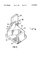
- FIG. 3 is a perspective view of the surgical blade removal and disposal device of FIG. 1.
- FIG. 4 is a rear view looking through plain IV--IV of FIG. 3 showing the blade removal and disposal device.
- FIG. 5 is a top plan view of the blade removal and disposal device of FIG. 3.
- the disposable case 40 is made of a molded plastic material and is comprised of a top half 42 and a bottom half 44 which are hinged in a conventional manner by hinges 46 and 48 so that the top half 42 and the bottom half 44 may be provided in the opened position of FIG. 2, or in a closed position of FIG. 2A.
- a pair of conventional integrally molded latches 50 and 52 are provided to facilitate the closure and locking of the case 40 for the disposal of any blades contained therein. It will be appreciated by those skilled in the art that many alternative forms of latching the case 40 may be used without departing from the spirit and scope of the present invention.
- the top half 42 is made of a transparent material while the bottom half 44 is provided with a large magnetic surface 54 covering the entire base of the bottom half 44 in a manner as taught in U.S. Pat. No. 4,013,109 to Sandel, issued Mar. 22, 1977, and incorporated herein by this reference.
- the magnetic surface 54 may be provided by a conventional rubber magnet material with counting indicia thereon to facilitate the counting and retention of blades and other sharp objects, i.e., suture needles and hypodermic needles. It will be appreciated by those skilled in the art that many alternative means for holding and counting sharp surgical objects may be used without departing from the spirit and scope of the present invention.
- Blade removal means are provided within the case 40 at a cut-out portion thereof as indicated generally at 60, and explained in detail hereinbelow.
- the outer surface of the upper half 42 of the case 40 is provided with a liner 62 on which a piece of adhesive tape 64 is applied.
- the adhesive tape 64 has a thin strip 66 which acts as a handle and which does not have any adhesive applied thereon.
- a nurse may grip the strip 66 and pull the adhesive tape 64 off the liner 62, then wrap the adhesive tape 64 around the upper half 42 and the bottom half 44 to secure the case 40 in a closed position.
- the adhesive tape 64 can be made from any conventional adhesive or securing tape. The reason for this security tape 64 is that the latches 50 and 52 may fail.
- latches 50 and 52 can become looser and looser. This allows case 40 to open following disposal to a "red" bag in the operating room, releasing hypodermic needles and other sharp objects outside the case 40. This can then put the housekeeping personnel or others at risk of being stuck by a contaminated needle as they pick up the bags for disposal. In today's concerns of Aids and hepatitis and other infectious diseases, it is important to secure all the sharp objects in a secured, rigid container to ultimate disposal.
- the blade removal device 60 is carved and molded from rigid plastic material or a metal fabricated one and is seated upon a base 67.
- the blade removal device 60 is carved so that it comprises a guiding wall 68, a blade seat 70 and a handle seat 72.
- the blade seat 70 is V-shaped and is defined on one side by the guiding wall 68 and on the other side by a curved dividing wedge-shaped wall 74, with a V-shaped restraining wall 76 provided therebetween.
- the dividing wedge-shaped wall 74 acts to separate the blade seat 70 from the handle seat 72, and has a sharp curved edge 77.
- the handle seat 72 is defined by a N-shaped portion 78, with its left leg portion molded integrally with the dividing wedge-shaped wall 74.
- the blade removal device 60 is described in connection with a conventional blade and handle as shown in FIG. 1, although it is appreciated by those skilled in the art that it may be used in connection with any conventional blade and handle.
- the blade 18 attached to the handle 10 is slid so that the blade 18 slides along the space between the pillar 68 and the dividing wedge-shaped wall 74, while the handle 10 occupies the handle seat 72 until the rear surface 36 of the handle 10 abuts an inner wall 80 of the N-shaped portion 78.
- the handle portion 12 of the handle 10 rests in the handle seat 72 while the entire length of the blade 18 lies within the blade seat 70 in the case 40 with the rear edge 34 of the blade 18 between the guiding wall 68 and the dividing wedge-shaped wall 74.
- the rear edge 34 of the blade 18 is separated from the neck portion 16 by a force exerted by the dividing wedge-shaped wall 74 such that the rear edge clears the rear end 22 of the inserted portion 14.
- the handle blade combination is used in a very natural and the same way and position as it is used in surgery--in an upright position with the sharp part of the blade facing down.
- the entire blade 18/handle 10 assembly is pressed downward in the blade removal device 60 with the blade 18 occupying the blade seat 70 and the front end of handle portion 12 occupying the handle seat 72.
- the sharp edges of the blade 18 are pointing downwardly at the magnetic surface 54, and the sharp curved edge 77 of the dividing wall 74 is fitted between the rear edge 34 of the blade 18 and the rear surface 36 of the neck portion 16 of the handle 10.
- This causes the rear of blade 18 to bow, and disengages the rear edge 34 of the blade 18 from the rear surface 36 of the handle 10 in a controlled and consistent manner.
- the handle 10 may then be pulled rearwardly away from the case 40 to cause the grooves 24 of the narrow portion 14 of the handle 10 to slide along the narrow portion 28 of the slot 26 until the narrow portion 28 of the slot 26 is completely disengaged from the grooves 24.
- the V-shaped restraining wall 76 restrains the blade 18 from moving rearwardly and allows the handle 10 to be cleanly disengaged from the blade 18.
- the blade seat 70 provides a seat for securely holding the blade 18 while the handle 10 is being disengaged. Furthermore, the sharp curved edge 77 of the dividing wedge-shaped wall 74 is used to separate the rear edge 34 of the blade 18 from the rear surface 36 of the handle 10 to achieve the disengagement. After the handle 10 has been completely pulled out of the case 40, the blade 18, which was resting in the blade seat 70, falls into the bottom half 44 of the case 40.
- the front end 20 of the handle 10 may be used to move the blade 18 to the desired location on the bottom half 44 of the case 40.
- the same procedure may be repeated to remove other used and/or contaminated surgical knife blades.
- the case 40 may be closed, the adhesive tape 64 applied to seal the top half 42 and the bottom half 44 together as well as the latches 50 and 52, and the case 44 together with its used blades and other sharp objects may be accounted for and disposed of in a safe, simple and efficient manner. If the case 40 needs to be reopened for recounting, the security tape 64 can be removed and rested in its original place over the liner 62 and replaced again following recounting.
Abstract
Description
Claims (8)
Priority Applications (1)
| Application Number | Priority Date | Filing Date | Title |
|---|---|---|---|
| US08/352,988 US5729879A (en) | 1992-03-11 | 1994-12-09 | Surgical blade removal and disposal device |
Applications Claiming Priority (2)
| Application Number | Priority Date | Filing Date | Title |
|---|---|---|---|
| US84947792A | 1992-03-11 | 1992-03-11 | |
| US08/352,988 US5729879A (en) | 1992-03-11 | 1994-12-09 | Surgical blade removal and disposal device |
Related Parent Applications (1)
| Application Number | Title | Priority Date | Filing Date |
|---|---|---|---|
| US84947792A Continuation | 1992-03-11 | 1992-03-11 |
Publications (1)
| Publication Number | Publication Date |
|---|---|
| US5729879A true US5729879A (en) | 1998-03-24 |
Family
ID=25305841
Family Applications (1)
| Application Number | Title | Priority Date | Filing Date |
|---|---|---|---|
| US08/352,988 Expired - Lifetime US5729879A (en) | 1992-03-11 | 1994-12-09 | Surgical blade removal and disposal device |
Country Status (1)
| Country | Link |
|---|---|
| US (1) | US5729879A (en) |
Cited By (11)
| Publication number | Priority date | Publication date | Assignee | Title |
|---|---|---|---|---|
| US20040111853A1 (en) * | 2002-11-12 | 2004-06-17 | Mike Hoftman | Scalpel blade remover and sharps container |
| US20070039845A1 (en) * | 2005-08-16 | 2007-02-22 | Xodus Medical Inc. | Surgical pad and tray |
| US20080300612A1 (en) * | 2007-05-21 | 2008-12-04 | Riza Erol D | Cutting blade storage apparatus |
| US20130019567A1 (en) * | 2011-07-22 | 2013-01-24 | Ansell Limited | Sharps container for removing and containing blades from round scalpel handles |
| US8752700B1 (en) | 2003-11-12 | 2014-06-17 | Moshe Mike Hoftman | Sharps container with blade remover, needle unsheather, latch and security alignment extensions |
| USD745155S1 (en) | 2013-03-14 | 2015-12-08 | Aspen Surgical Products, Inc. | Blade disarmer |
| US9622773B2 (en) | 2012-03-19 | 2017-04-18 | Aspen Surgical Products, Inc. | Side activated safety scalpel for left and right hand users with blade removal system |
| USD813390S1 (en) | 2016-01-15 | 2018-03-20 | Aspen Surgical Products, Inc. | Surgical scalpel blade attachment |
| US10064647B2 (en) | 2015-10-09 | 2018-09-04 | Aspen Surgical Products, Inc. | Scalpel blade remover |
| US10299825B2 (en) | 2014-10-03 | 2019-05-28 | Aspen Surgical Products, Inc. | Sharps blade applicator and storage device |
| US11278310B2 (en) | 2016-03-21 | 2022-03-22 | Aspen Surgical Products, Inc. | Safety scalpel handle |
Citations (4)
| Publication number | Priority date | Publication date | Assignee | Title |
|---|---|---|---|---|
| US4106620A (en) * | 1977-10-03 | 1978-08-15 | Brimmer Frances M | Surgical blade dispenser |
| US4180162A (en) * | 1978-12-04 | 1979-12-25 | Magney Herbert C | Combination dispenser-disposal cartridge for a surgical blade |
| US4270416A (en) * | 1978-04-21 | 1981-06-02 | Jermed Limited | Scalpel blade extractor |
| US5088173A (en) * | 1989-04-26 | 1992-02-18 | Kromer Martin W | One-time-use precision-blade-bending scalpel blade remover-receptacle |
-
1994
- 1994-12-09 US US08/352,988 patent/US5729879A/en not_active Expired - Lifetime
Patent Citations (4)
| Publication number | Priority date | Publication date | Assignee | Title |
|---|---|---|---|---|
| US4106620A (en) * | 1977-10-03 | 1978-08-15 | Brimmer Frances M | Surgical blade dispenser |
| US4270416A (en) * | 1978-04-21 | 1981-06-02 | Jermed Limited | Scalpel blade extractor |
| US4180162A (en) * | 1978-12-04 | 1979-12-25 | Magney Herbert C | Combination dispenser-disposal cartridge for a surgical blade |
| US5088173A (en) * | 1989-04-26 | 1992-02-18 | Kromer Martin W | One-time-use precision-blade-bending scalpel blade remover-receptacle |
Cited By (14)
| Publication number | Priority date | Publication date | Assignee | Title |
|---|---|---|---|---|
| US20040111853A1 (en) * | 2002-11-12 | 2004-06-17 | Mike Hoftman | Scalpel blade remover and sharps container |
| US8596453B2 (en) | 2002-11-12 | 2013-12-03 | Mike Hoftman | Scalpel blade remover and sharps container |
| US8752700B1 (en) | 2003-11-12 | 2014-06-17 | Moshe Mike Hoftman | Sharps container with blade remover, needle unsheather, latch and security alignment extensions |
| US20070039845A1 (en) * | 2005-08-16 | 2007-02-22 | Xodus Medical Inc. | Surgical pad and tray |
| US20080300612A1 (en) * | 2007-05-21 | 2008-12-04 | Riza Erol D | Cutting blade storage apparatus |
| US8800766B2 (en) * | 2011-07-22 | 2014-08-12 | Ansell Limited | Sharps container for removing and containing blades from round scalpel handles |
| US20130019567A1 (en) * | 2011-07-22 | 2013-01-24 | Ansell Limited | Sharps container for removing and containing blades from round scalpel handles |
| US9622773B2 (en) | 2012-03-19 | 2017-04-18 | Aspen Surgical Products, Inc. | Side activated safety scalpel for left and right hand users with blade removal system |
| US10292729B2 (en) | 2012-03-19 | 2019-05-21 | Aspen Surgical Products, Inc. | Side activated safety scalpel for left and right hand users with blade removal system |
| USD745155S1 (en) | 2013-03-14 | 2015-12-08 | Aspen Surgical Products, Inc. | Blade disarmer |
| US10299825B2 (en) | 2014-10-03 | 2019-05-28 | Aspen Surgical Products, Inc. | Sharps blade applicator and storage device |
| US10064647B2 (en) | 2015-10-09 | 2018-09-04 | Aspen Surgical Products, Inc. | Scalpel blade remover |
| USD813390S1 (en) | 2016-01-15 | 2018-03-20 | Aspen Surgical Products, Inc. | Surgical scalpel blade attachment |
| US11278310B2 (en) | 2016-03-21 | 2022-03-22 | Aspen Surgical Products, Inc. | Safety scalpel handle |
Similar Documents
| Publication | Publication Date | Title |
|---|---|---|
| US4989307A (en) | Apparatus for facilitating of the removal and disposal of medical needles | |
| US4318473A (en) | Surgical blade removal and disposal device | |
| US4736844A (en) | Container for the disposal of sharps | |
| AU712212B3 (en) | A surgical scalpel with retractable guard | |
| US7497330B2 (en) | Apparatus for sharp implement transfer, counting and temporary disposal or storage | |
| JP4038238B2 (en) | Knife with retractable blade | |
| US4903390A (en) | Scalpel blade remover and blade storage apparatus | |
| US5097950A (en) | System for the disposal of medical waste | |
| US5729879A (en) | Surgical blade removal and disposal device | |
| US5449068A (en) | Surgical blade remover | |
| US5938063A (en) | Hinged, latchable box as for medical sharps | |
| JPH01502164A (en) | A containment device for safely removing, storing, and handling hypodermic syringes or hypodermic needles. | |
| US5183156A (en) | Needle removal/containment and transport apparatus for safe storage and disposal of hypodermic needles/syringe assemblies | |
| NZ538442A (en) | Surgical scalpel with retractable guard | |
| US5031767A (en) | Needle removal/containment and transport apparatus for safe storage and disposal of hypodermic needles/syringe assemblies | |
| US4956907A (en) | Method for safely removing, storing and ultimately disposing of needles from hypodermic needle/syringe assemblies | |
| EP1545346A1 (en) | Spring-actuated, retractable-bladed surgical scalpel | |
| US4848570A (en) | Sharps disposal system | |
| US6807737B1 (en) | Ergonomic opener for intravenous bag packaging | |
| US5368580A (en) | Disposable safety guard for syringe needles and the like | |
| US5275280A (en) | Device and method of removal and storage of syringe needle | |
| US5205409A (en) | Needle removal/containment and transport apparatus for safe storage and disposal of hypodermic needles/syringe assemblies | |
| US5363862A (en) | Disposable surgical instrument passer | |
| US8752700B1 (en) | Sharps container with blade remover, needle unsheather, latch and security alignment extensions | |
| US8596453B2 (en) | Scalpel blade remover and sharps container |
Legal Events
| Date | Code | Title | Description |
|---|---|---|---|
| STCF | Information on status: patent grant |
Free format text: PATENTED CASE |
|
| FEPP | Fee payment procedure |
Free format text: PAT HLDR NO LONGER CLAIMS SMALL ENT STAT AS INDIV INVENTOR (ORIGINAL EVENT CODE: LSM1); ENTITY STATUS OF PATENT OWNER: LARGE ENTITY Free format text: PAYOR NUMBER ASSIGNED (ORIGINAL EVENT CODE: ASPN); ENTITY STATUS OF PATENT OWNER: LARGE ENTITY |
|
| FPAY | Fee payment |
Year of fee payment: 4 |
|
| AS | Assignment |
Owner name: AMSOUTH BANK, TENNESSEE Free format text: SECURITY INTEREST;ASSIGNOR:DEROYAL INDUSTRIES, INC.;REEL/FRAME:012822/0959 Effective date: 20020415 |
|
| FPAY | Fee payment |
Year of fee payment: 8 |
|
| AS | Assignment |
Owner name: REGIONS BANK, TENNESSEE Free format text: AMENDED AND RESTATED SECURITY AGREEMENT;ASSIGNOR:DEROYAL INDUSTRIES, INC.;REEL/FRAME:020325/0001 Effective date: 20071227 |
|
| FPAY | Fee payment |
Year of fee payment: 12 |
|
| AS | Assignment |
Owner name: REGIONS BANK, TENNESSEE Free format text: SECURITY INTEREST;ASSIGNOR:DEROYAL INDUSTRIES, INC.;REEL/FRAME:062079/0779 Effective date: 20191229 |