US5734984A - Telephone system for mobile wireless telephone services - Google Patents
Telephone system for mobile wireless telephone services Download PDFInfo
- Publication number
- US5734984A US5734984A US08/589,573 US58957396A US5734984A US 5734984 A US5734984 A US 5734984A US 58957396 A US58957396 A US 58957396A US 5734984 A US5734984 A US 5734984A
- Authority
- US
- United States
- Prior art keywords
- radio base
- portable
- base stations
- radio
- portable telephone
- Prior art date
- Legal status (The legal status is an assumption and is not a legal conclusion. Google has not performed a legal analysis and makes no representation as to the accuracy of the status listed.)
- Expired - Lifetime
Links
Images


Classifications
-
- H—ELECTRICITY
- H04—ELECTRIC COMMUNICATION TECHNIQUE
- H04W—WIRELESS COMMUNICATION NETWORKS
- H04W68/00—User notification, e.g. alerting and paging, for incoming communication, change of service or the like
Definitions
- This invention relates to wireless communication systems, and more particularly, to a telephone system for providing mobile wireless telephone service to portable telephone sets and the like.
- a cordless phone is usually functional over a range of within about 30 meters of its associated base station.
- the associated cordless base station set is connected via a telephone line to a central office exchange, just as a typical telephone is connected.
- a cellular phone can be functional over an area ranging from hundreds of square miles to an area including vast portions of a continent.
- Cellular phones are supported by cellular telephone systems which typically include mobile telephone central switching exchanges each of which is connected to a multitude of geographically distributed cellular radio stations via a corresponding multitude of multi-channel trunks. In populous areas, cellular systems are rapidly becoming overloaded with the result that mobile telephone services are sometimes degraded or from time to time momentarily unavailable.
- CT2 As a compliment to the cellular systems, a new standard referred to as CT2 has been adopted in some countries such as the United Kingdom. This standard defines low power radio links in a different portion of the radio frequency spectrum with respect to that of the cellular spectrum and was originally intended as a cordless phone standard. A typical low power link is usually functional over distances of up to about 200 meters or so. While the CT2 standard was evolving, it was envisaged that it would apply to wireless telephony wherein the wireless portable telephone set would be operationally confined to the immediate area of one particular related cordless base station or radio base station. Any provision for a wireless link to be transferrable between two or more radio base stations during the progress of a telephone call was not specified in the standard.
- the portable telephone service is available at identified fixed antenna locations. When adjacent to one of the fixed antenna locations, a portable telephone user is able to initiate a telephone call. In order for the initiated call to progress to a connection with a called party, the wireless telephone service provider must be able to identify the user's portable telephone set for purposes of billing.
- the portable telephone set's identity must have been registered in the wireless system and the presence of the portable set within the service area of one of the fixed antenna locations must be of record. Record of the presence of the portable telephone is contingent upon the portable telephone set user having pressed an active button on the portable telephone set or at least having attempted to originate a telephone call from the portable set, after having entered the service area of an identified antenna location. Otherwise the service provider is unaware of the physical presence of the portable telephone set. If the service provider apparatus is able to identify, either within the wireless telephone facility or in some other associated facility, a record confirming that the user's portable set is subscribed to wireless service, then wireless service is provided as appropriate. Mobility is not provided. If during the progress of the telephone call the portable set user happens to carry the portable telephone set beyond the service area of the identified antenna location, the telephone call is cut off by failure of the radio link between the portable telephone set and the antenna.
- the lack of ability for the wireless service provider's operation to complete calls to portable sets, without the portable set user having first pro-actively made record of his presence, and the lack of mobility reduces the quality of service to the user and likewise reduces the revenue potential associated with the service provider's investment in the wireless telephone system.
- a low-power wireless telephone system similar to that introduced by O'Neill et al can be used to provide mobile wireless telephone services in both private and public service areas.
- telephone traffic characteristics in public areas, where message rate billing is in effect are significantly different than in private service areas.
- public service areas it has been found that although many potential users may be within a given service area, call frequency and call holding times are reduced as compared with typical telephone traffic in a private service area.
- the CT2 standard spectrum can be more efficiently utilized for mobile wireless telephony in public service areas than was previously expected, and that the operating energy requirement of an active on hook portable set may be reduced.
- a telephone system for providing wireless telephone services in public areas in accordance with the invention is arranged such that each of a plurality of paging signal areas includes one beacon signal zone of lesser area and contained within the paging signal functional area.
- Beacon signals for soliciting responses from portable sets within the paging area are broadcast from time to time from at least a radio base station in each of the beacon zones.
- a portable set Upon entering a beacon zone, a portable set is intended to respond to a broadcast of a beacon signal by broadcasting its identity to make its presence of record as being within the paging area. Thereafter no further responses to beacon signals are required unless the portable set moves to another beacon zone.
- An alternative may be to require that a beacon signal of the same identity be received at least twice consecutively by the portable telephone set, before the portable telephone set responds. It may also be advantageous to require that the portable telephone set transmit a signal for making record of its presence in the service area with the telephone system every few hours or so to confirm its continued presence within the system or an operating zone therein.
- a portable telephone set that are receptive to a timing instruction from the telephone system, whereby after an elapsed time as specified by the timing signal, a portable telephone set will automatically respond to the next received beacon signal or series of received beacon signals by again transmitting a signal for making record of its presence in the service area of the wireless telephone system.
- a digital telephone system provides for radio links between portable sets, including itinerant portable sets, and any of a plurality of radio base stations, each of which is connected by a communications conduit to the digital telephone system.
- the digital telephone system comprises a port circuit for interfacing an operating signal format of the communications conduit with an operating signal format of the digital telephone system.
- the operating signal format of the communications conduit includes a bidirectional message channel and at least one bidirectional communication channel, wherein the operating signal format of the digital telephone system includes frame organized channels.
- a service controller receives and transmits message signals via the frame organized channels, and a switch is responsive to the service controller for transferring communication signals from a frame organized channel of any one port to a frame organized channel of any other port.
- each cell manager includes means responsive to signal strengths as received from time to time at any of its radio base stations including a radio base station being radio linked with a portable set, for transferring the radio link to another of its radio base stations contingent upon the other radio base station having received a greater signal strength from the portable set.
- each cell manager may act in concert with another cell manager to effect a handoff of the radio link from said radio base station to a one of the plurality of radio base stations in an neighbour cell.
- each group having a boundary, a portion of each is boundary being overlapped by at least one other boundary, each group including at least one radio base station in common with said another group, each radio base station being capable of supporting a radio link for communications with a portable telephone set;
- the itinerant user responsive to a call request wherein the itinerant user is a called party, paging the recorded portable set via otherwise idle ones of the radio base stations of the group within which the portable set is registered, whereby the portable set of the called itinerant user may be called via the telephone system without any requirement for the user to have prior knowledge of or to have taken any action in relation to the wireless telephone service.
- FIG. 1 is a block schematic diagram of a small digital telephone system which is operable to provide wireless telephony service in accordance with the invention
- FIG. 2 is an illustration of the frequency plan for the Common Air Interface (CAI) CT2 standard
- FIG. 3 is an illustration of a relationship between a time division multiplex signal format used in the small digital telephone system and a time compression multiplex (TCM) signal format also used in the small digital telephone system in FIG. 1;
- TCM time compression multiplex
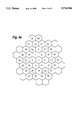
- FIG. 4a illustrates one example of a functional micro-cell community which may be provided by the small digital telephone system illustrated in FIG. 1;
- FIG. 4b illustrates another example of a functional micro-cell community which is particularly adapted, in accordance with the invention, for providing wireless telephony service for an itinerant user and which may be provided by the small digital telephone system illustrated in FIG. 1;
- FIG. 4c is a symbolic illustration of a plurality of radio base station antennas for providing a typical cell as shown in FIG. 4b;
- FIG. 5a shows the relationship between the thresholds associated with establishing and maintaining a radio link
- FIG. 5b shows the thresholds of FIG. 5a with respect to the cell community of FIG. 4a;
- FIG. 6a illustrates a software architecture used in a service controller within the small digital telephone system in FIG. 1;
- FIG. 6b shows a cell manager's functional partitioning during an arbitration function
- FIG. 7 illustrates an example of a code format suitable for providing a beacon signal compatible with operation as specified by the CT2 standard and useful in the operation of the telephone system in FIG. 1;
- FIG. 8 illustrates an example of memory lists for defining cell topology within beacon zones and paging areas illustrated in FIG. 4b;
- FIG. 9 is a flow chart illustration of a recordation process used to make record of the presences of a portable telephone set within an operating service area of the telephone system illustrated in FIG. 1;
- FIG. 10 is a flow chart illustration of an initial part of a call setup process as it is adapted for operating in conjunction with a paging area as exemplified in FIG. 4b.
- the invention is exemplified within a small digital telephone system as illustrated in FIG. 1, which itself may be supported by either a central or branch exchange (not shown) via either analog or digital lines or trunks 35 connected therebetween.
- Conventional wireline telecommunication services may be provided for a plurality of station sets at 34 via a port group 32a connected to a service controller 110 via a switch 137 and by transmit and a receive lines 32b.
- the trunks 35 are similarly coupled as shown via a port group 32b and transmit and a receive lines 33b to the service controller 110.
- Radio base stations 111a -111n are connected similarly via a port group 112 and transmit and a receive lines 113, via a switch 137, to the service controller 110.
- Each radio base station provides a wireline interface and a radio link interface for coupling communications signals with a portable set 114 via a radio link 122.
- the radio base stations 111a-111n are loosely arranged into several groups, spaced apart one group from the other, each group being assigned to one of a plurality of geographic cells, somewhat as exemplified in FIGS. 4a and 4b. Spacing between the radio base stations in any cell may be in a range of a meter or so. The preferred number and spacing of radio base stations in any one cell is determined by the telephony traffic for which the cell is intended to serve.
- each radio frequency carrier can be utilized as one full-duplex channel or radio link with a bandwidth of 100 KHz.
- each channel is provided in time-division duplex (TDD) operation. That is, one half-duplex time slot or burst of each frequency may be used for communication from the base station to a portable handset and a following half-duplex time slot or burst of the same frequency is used for communication between the portable handset and the base station.
- TDD time-division duplex
- the wireline signal format provides transmit and receive bursts for first and second voice/data channels at 64 Kb/s. These are usually referred to as B-channels.
- the wireline signal format also provides first and second message channels of which only the first message channel is utilized at 8 kb/s in this example.
- Each of the transmit and receive bursts includes a balance bit and begins and ends with start and stop bits, not shown.
- Each wireline signal stream is interfaced with a predetermined pair of time slots in receive and transmit serial bit streams in the operating signal format of the service controller 110. Only the receive serial bit stream is shown in FIG. 3.
- the telephone system illustrated in FIG. 1 behaves logically as though intelligence were distributed across the plurality of station sets 34, trunks 35, and the radio base stations 111a-111n as well as the service controller 110. This capability is achieved by combining a broadcast message architecture and a point to point message architecture so that functional messages facilitate control communication between intelligent entities and stimulus messages facilitate control communication with stimulus entities.
- Each of the radio base stations 111a-111n is in logical communication with the service controller 110. From the viewpoint of its logical structure, the physical smallness of the telephone system allows for liberties that may not be available in a much larger system.
- the logical structure behaves as if each telephone terminal and radio base station has its own processing power, generating and sending its own messages to every other terminal or station in the system.
- Instantaneous and running Received Signal Strength Indications (RSSI)s are provided from each radio base station for use in controlling functions related to initiation and maintenance of radio links with portable sets.
- RSSI Received Signal Strength Indications
- the instantaneous operating conditions of any radio link are ascertained by the operating radio base station, the decision processing power of the radio base stations is actually located in the service controller 110.
- each radio base station is limited to supporting only one radio link at a time, there must be at least as many radio base stations as there are radio links to be maintained with portable telephone sets, at any one instant.
- FIG. 4a a typical cell community structure used in providing a wireless service is illustrated.
- the cells are portrayed as hexagonal areas, where in actual fact the boundary of a cell is defined as a line beyond which the propagation strength or power of a radio link is deemed to be too attenuated to maintain communications. This will result in a cell boundary of an irregularity somewhat like that as exemplified in FIG. 5a.
- O'Neill et al introduced the terms immediate neighbours and radio propagation neighbours. With respect to cell 1 of FIG. 4a, the immediate neighbours are cells 2, 3, 4, 5, 6 and 7.
- cells 2-19 inclusive are cells wherein one or more radio base stations might receive or see a radio link from a portable set even though the cell may be completely disjointed in terms of an operational traffic cell.
- Portable user density in a limited radio channel spectrum is provided by channel reuse.
- 40 channels have been allocated in the radio spectrum. Allocation/selection of a specific channel between a portable set and a radio base station is done using dynamic channel allocation (DCA).
- DCA dynamic channel allocation
- any of the 40 channels can be selected or allocated by a radio base station, in a real operating environment, not all 40 channels can be used in each cell simultaneously because of undue interference between adjacent channels, having regard for receivers of modest selectivity characteristics and modest cost. Hence it is unlikely that more than 21 channels may be simultaneously useful within a cell.
- the maximum number of channels which can be used in a cell is limited to the number of radio base stations provided in the cell.
- the number of channels actually useable for telephone communication in a cell is further limited by dynamic operating conditions.
- a reduction in the wireless facility and capital investment for a given number of portable telephone sets may be achieved with an acceptable grade of service by organizing groups of cells into mutually exclusive beacon signal broadcasting zones, each lying within a larger or broader paging area. Beacon signals broadcast from the cells of any one zone are arranged to be distinguishable from beacon signals broadcast from the cells of another zone.
- a portable set which has previously identified itself and received a confirmation in one paging area will only again transmit its identity in response to having received a zone beacon signal associated with the beacon zone of another paging area. Of course this usually only happens when the portable set is carried into an adjacent paging zone.
- the first paging area 41 includes a plurality of cells 411-432, and 453-455, from which paging signals may be transmitted.
- a first beacon zone consists of a lesser plurality of the cells, namely cells 411-424.
- the second paging area 44 includes a plurality of cells 441-455, and 425-432, from which paging signals may be transmitted.
- a second beacon zone consists of a lesser plurality Of the cells, namely cells 441-452.
- the third paging area 47 includes a plurality of cells 471-480, 483, 484, 425-432 and 453-455 which are transmitters of paging signals.
- a third beacon zone consists of a lesser plurality of the cells, namely cells 471-480, 483 and 484. As can be seen from the illustration, the paging areas overlap but the beacon zones are separated one from another by a boundary of at least one cell in width, to provide buffer regions.
- the beacon signal associated with each beacon zone is identified by a unique code reserved for this purpose. An example of a code format of the beacon signal is discussed later with reference to FIG. 7. In order that a portable set 114 be operable to be automatically registered in the service area of the service provider, it must be capable of distinguishing the beacon signal by its unique code.
- beacon signal broadcast occurrences in any one cell are generally periodic but may become intermittent as wireless telephone traffic increases. Also not all the otherwise idle radio base stations in any given cell need be regular transmitters of the beacon signal. In fact, beacon signal broadcasts from within any one cell need not be regular events. Time intervals of up to several minutes between beacon signal broadcasts are acceptable in normal operation.
- the data consists of 8 octets (64 data bits), having a period of 6 milliseconds.
- the 8 octets are broadcast in a zone beacon signal from at least one radio base station in each cell in the beacon zone.
- the broadcast of the zone beacon signal from any one radio base station consists of a repetition of the data for a duration of 3 seconds every 30 seconds unless the broadcast of the zone beacon signal is preempted by call traffic.
- octets 7 and 8 are provided for checking or verifying that the preceding data has been correctly received at the portable set.
- Octets 5 and 6 are used to uniquely identify the wireless communications service provider.
- Bits 8-2 of the fourth octet are set to all 1s to indicate that the beacon signal is a secondary service signal broadcast from a radio base station and bit 1 is not specified as it is reserved for future use, (RFU).
- Octet 3 is used to uniquely identify the beacon zone from whence the signal is broadcast such that the portable set may recognize that it has been moved across a boundary from one beacon zone to another and be enabled to respond to the zone beacon signal.
- Octet 2 is used to uniquely identify the cell location such that the portable set may be enabled to indicate the cell from whence it has received the zone beacon signal, if and when it subsequently responds to the zone beacon signal.
- Each of the bits in the first octet have an indicative function as follows:
- TCA Traffic Channel Available
- SRA Signalling Receiver Available
- ICI Incoming Call Identification
- ALR Automatic Location Registration
- Power (PWR) indicates one of two power levels with which a particular beacon signal was transmitted
- IRI In Range Indication
- bits 2 and 1 in this example are set to 0 and 1 respectively.
- the wireless telephone system responds to any incoming call destined for a user having been recorded with the system by broadcasting a paging signal identifying the user's portable set 114 preferably from at least one radio base station in each of the cells in the paging area.
- the paging signal may be broadcast several times from each of the cells, until the appropriate response from the user's portable set 114 is received. This response need not be received in the cell in which the user is actually located in order that a radio link be initiated. All the radio base stations in the cell where the user's portable set 114 is present may already be occupied with radio links or the channel scanning of the user's portable set 114 may have been coincident with the broadcast of the paging signal from an adjacent cell. In any event a radio link will be established and subsequently optimized within prevailing mobility operating parameters and constraints of the wireless telephone system.
- POLS Portable Originated Link Setup
- RSSI Radio Signal Strength Indicator
- the Switch Originated Link Setup (SOLS) threshold 902 is used by radio base stations during switch originated calls.
- the radio base stations will not accept an call set-up response from a portable terminal unless an RSSI level is greater than the SOLS threshold.
- the purpose of this threshold is to prevent very weak links from preempting establishment of a stronger link which may be available in another cell. In an ideal situation, this threshold will approach the maximum radio propagation range.
- the neighbourhood threshold 903 has an RSSI level which is only known to the service controller. It is used to determine the search neighbourhood during link set up arbitration and mobility. When the RSSI level is less than this threshold, the radio propagation neighbourhood is used, otherwise the immediate neighbourhood is used.
- the Portable Originated Link Setup (POLS) threshold 904 is used by the radio base station during portable originated calls.
- the radio base station will not respond to the portable if the RSSI level does not meet the POLS threshold.
- the purpose of this threshold is to increase the probability of a good link being established immediately with the portable.
- the cell threshold 905 coincides with the installation (provisioning) boundary. It is not used by the radio base station explicitly, but is used during a lost portable recovery to help determine the need for an intra-cell or inter-cell search.
- the cell threshold defines the traffic cell.
- Arbitration is a process of attempting to establish a better radio link than an existing radio link.
- the arbitration threshold 906 is one where the RSSI level is very good and a better radio link for serving a specific portable would have little added benefit.
- dynamics of RSSI rates of variation may be advantageously utilized to recognize and distinguish between mobile and stationary portables for maintenance of radio links.
- a fast handoff response may be provided for a portable set user who is walking away from a cell center, while a slow handoff response is provided for a stationary user. This dynamic assignment of the slower handoff response maintains adequate radio links for stationary portables and permits optimal control resources to be concentrated upon maintaining acceptable radio links with mobile portable set users.
- each of the memory lists consists of a paging area list which includes a beacon zone list.
- any subsequent paging for the portable set is limited to the cells of the paging area as defined by the paging area list.
- the system causes a beacon signal to be transmitted from time to time by a radio base station in each cell of each beacon zone. If the user crosses from one beacon zone to another and the user's portable set is idle, the portable set responds to having received a new beacon signal by again transmitting its unique code to effect a new recordation of its presence, after which it receives confirmation of being recorded.
- thrashing recordations Frequent and unnecessary occurrences of recordation, herein termed as thrashing recordations, may be deleterious to the operation of the system because these functions consume substantial real time in the service controller 110 and also unnecessarily occupy radio spectrum bandwidth.
- Having a buffer of at least one cell width between each of the beacon zones substantially reduces the likelihood of thrashing recordations between any two beacon zones.
- Potential for thrashing can also be reduced by careful geographic planning such that the edges of beacon zones do not coincide in a more or less parallel relationship with a location that many portable user's may frequent, such as a main thoroughfare. However, as this is not always convenient, other precautions can be taken to further reduce instances of thrashing.
- the portable set may be arranged to require consistent reception of similar beacon signals for a period of more than a minute of time without receipt of any other beacon signal, before attempting to make record of its presence within the paging area.
- the service controller 110 may include a recordation inhibit instruction along with a confirmation of recordation whereby the portable set is caused to ignore any beacon signals for a period of time which may extend up to 5 minutes or so.
- the software architecture of the service controller 110 is illustrated in relation to interaction between functional entities located in a community sub-system 200.
- the wireless community sub-system 200 interfaces with an external network 201 using a functional message protocol via a D-channel. This interface is referred to as the External Network Interface (ENI).
- ENI External Network Interface
- the wireless community sub-system 200 is responsible for maintaining centralized control over the entire cell environment.
- the functional entities of the wireless community sub-system 200 provide mobility services to cell managers 211 and 212, portable emulators 202, and the external network 201.
- the cell managers are provided with logical addresses (LADs) and interact with a physical group of radio base stations which provide a specific coverage area.
- LADs logical addresses
- the cell manager 211 controls radio drivers 203, 204, and 205 of radio base stations A, B and C, respectively, whereas the cell manager 212 controls radio drivers 206 and 207 of another group of radio base stations, D and E, respectively.
- Cell managers use the functional signalling protocol to communicate information to each other.
- the portable emulator 202 and driver 213 will link up to a radio driver during a radio link with a portable. This link is dynamic and only exists during a call, once a call has been set up.
- the virtual network interface (VNI) 214 between the portable driver 213 and community sub-system 200 is provided by the connection request server 230 in FIG. 6b.
- This interface is procedural and provides the link originate and link reject functionalities, for example, request from the portable driver 213 to find a portable, acceptance of the portable set's identity, response from the connection request server to the portable driver when link request as failed, etc.
- a virtual radio interface (VRI) 215 is the interface between the cell managers and the radio drivers.
- FIG. 6b shows a software architecture of the community sub-system 200 of FIG. 6a.
- the community sub-system's functional entities include a locator 220, a community data manager 225 which has access to the community database 226 wherein the memory list is stored, a connection request server 230 and a validation server 250.
- the locator 220 is responsible for finding a recorded called portable set within a minimum duration of time after arrival of an incoming call.
- the locator maintains a record of the last paging area in which each portable set was present. It tries to locate a specific portable set upon arrival of an incoming call by broadcasting a paging signal identifying the called portable set in the paging area. If the portable set does not respond within a short time, the call progress may be diverted to provide the calling party with an appropriate service tone or announcement, or the call progress may simply be returned to the associated external facility.
- FIG. 9 is a flow chart illustration of the recordation process required in the telephone system, to make record of the presence of a portable telephone set within the service area of a wireless telephony service provider.
- these functions are required to be executable during the normal operation of the telephone system, normal operation including the basic tasks such as monitoring for requests for service etc., via line links and air links.
- the recordation function is waiting for the results of a physical action such as the actual radio transmission or radio reception of a signal
- the normal operation of the telephone system continues until the required results are signalled to the service controller 110.
- the service controller 110 is directed in its operations in accordance with predetermined priorities of interrupt events which may take priority over some or all of the basic tasks.
- a zone beacon interrupt is generated, as indicated in a function box 303.
- the service controller determines if an unserviced zone beacon interrupt exists, as shown in decision box 302. If NO, the normal operation of the telephone system continues. If YES, however, the service controller refers to its busy/idle map (not shown) in combination with its zone beacon memory lists as exemplified in FIG. 8 to select idle radio base stations for subsequent radio transmission of the zone beacon signal, as specified in a function box 305. This selection may include all idle radio base stations in every cell within a beacon zone or it may be limited to some lesser number of the radio base stations.
- At least one radio base station in each of the cells is selected.
- Function box 307 requires that each selected radio base station transmits a beacon signal which is identifiable by any receiving portable as being associated with the beacon zone wherein the radio base station is physically located. Thereafter, any idle radio base station is available to receive a response signal from a portable telephone set as indicated in function box 309.
- the identity of the portable telephone set is compared with the data base of registered identities to determine if the portable telephone set is properly serviceable by the service provider, as indicated in a decision box 310. If YES in relation to at least one response signal, the identity of the responding portable telephone set is recorded in association with the paging area in which the receiving radio base station is physically located.
- a confirmation signal is transmitted via the radio base station, as indicated in a function box 313, whereby the portable telephone set is intended to be nonresponsive to subsequent beacon signals of origin within the same beacon zone.
- the recordation process is complete for the moment while the normal operation of the wireless telephone system continues. If NO is determined in the decision box 310, the recordation process ceases for the moment while the normal operation of the wireless telephone system continues.
- FIG. 10 is a flow chart illustration of an initial part of the call set process as it is adapted to operating in conjunction with a paging area of the wireless telephone system.
- the service controller may receive a call set up request.
- the request may be received from another telephone facility via the port group 32b, shown in FIG. 1.
- an identity of the called party is compared with identities associated with portable telephone sets recently recorded as being within any of the paging areas, as required in a decision box 322. If NO correspondence is found with a called party's portable telephone set, the service controller processes the call set up request in typical wireline telephony manner.
- the service controller refers to its busy/idle map to determine if the identified portable telephone set is busy or not, as indicated in decision box 324. If the called set is not busy, as indicated in a function box 325, the service controller 110 selects an idle base station in each of the cells indicated in the paging area list of last recorded presence, to the extent that any existing wireless telephone traffic allows. If at least one idle base station is selected, as determined in a decision box 330, the service controller 110 attempts to complete the call set up. The service controller 110 directs the radio base station or stations as selected to transmit a page signal identifying the called portable telephone set.
- a radio link is established with the called portable set via the radio base station having first indicated to the service controller that it has received the response, in accordance with the requirement of a function box 333. Thereafter the operation of the wireless telephone system may include optimization of the established radio link, for example, in a manner as disclosed in the previously mentioned application by O'Neill et al.
- the feature parameters of the telephone facility from whence the call set up request was communicated are determined in accordance with a decision box 336 to see if said facility is able to retrieve the call progress from the wireless telephone system. If it can, signalling appropriate for this function may be generated by the service controller and transmitted via the group port 32b, as indicated in a function box 327. If not, the call may be completed to a service facility, as indicated in function box 329 which may, for example, provide an audible progress tone to the calling party, or may offer a voice messaging opportunity to the calling party.
Abstract
Description
Claims (13)
Priority Applications (1)
| Application Number | Priority Date | Filing Date | Title |
|---|---|---|---|
| US08/589,573 US5734984A (en) | 1993-11-30 | 1996-01-22 | Telephone system for mobile wireless telephone services |
Applications Claiming Priority (2)
| Application Number | Priority Date | Filing Date | Title |
|---|---|---|---|
| US15948693A | 1993-11-30 | 1993-11-30 | |
| US08/589,573 US5734984A (en) | 1993-11-30 | 1996-01-22 | Telephone system for mobile wireless telephone services |
Related Parent Applications (1)
| Application Number | Title | Priority Date | Filing Date |
|---|---|---|---|
| US15948693A Continuation | 1993-11-30 | 1993-11-30 |
Publications (1)
| Publication Number | Publication Date |
|---|---|
| US5734984A true US5734984A (en) | 1998-03-31 |
Family
ID=22572771
Family Applications (1)
| Application Number | Title | Priority Date | Filing Date |
|---|---|---|---|
| US08/589,573 Expired - Lifetime US5734984A (en) | 1993-11-30 | 1996-01-22 | Telephone system for mobile wireless telephone services |
Country Status (1)
| Country | Link |
|---|---|
| US (1) | US5734984A (en) |
Cited By (25)
| Publication number | Priority date | Publication date | Assignee | Title |
|---|---|---|---|---|
| US5873033A (en) * | 1995-02-06 | 1999-02-16 | Telia Ab | Method and arrangement for transfer between a cordless telecommunication system and a cellular mobile telecommunication system |
| US6035203A (en) * | 1996-12-24 | 2000-03-07 | Lucent Technologies Inc. | Time based paging for mobile telephone units |
| US6035337A (en) * | 1997-05-30 | 2000-03-07 | International Business Machines Corp. | Method and system for managing data flow within a collaboration system using proximity determination modules |
| US6292667B1 (en) * | 1998-05-05 | 2001-09-18 | Telefonaktiebolaget Lm Ericsson (Publ) | Multicell area paging for cellular telecommunications system |
| US20010036834A1 (en) * | 2000-03-03 | 2001-11-01 | Subir Das | Supporting fast intra-domain handoffs and paging in wireless cellular networks |
| US6393003B1 (en) * | 1997-08-22 | 2002-05-21 | Samsung Electronics, Co., Ltd. | Semi-soft handoff method that uses multiple common frequency |
| US6594493B1 (en) * | 2000-02-09 | 2003-07-15 | Lucent Technologies Inc. | Paging arrangement for wireless communications |
| US20030145092A1 (en) * | 2002-01-28 | 2003-07-31 | Docomo Communications Laboratories Us, Inc. | Method and apparatus for dormant mode support with paging |
| US6647264B1 (en) * | 1998-09-24 | 2003-11-11 | Nec Corporation | Mobile communication system and method for transmission of connection less packets |
| US20040203770A1 (en) * | 2002-11-19 | 2004-10-14 | Chen An Mei | Method and apparatus for efficient paging and registration in a wireless communications network |
| WO2004095848A2 (en) * | 2003-04-16 | 2004-11-04 | Motorola, Inc. | Method and device for distributing communication signals |
| US6816729B1 (en) * | 1998-03-06 | 2004-11-09 | Nokia Corporation | Handover method |
| US20050232200A1 (en) * | 2002-10-04 | 2005-10-20 | Jeong Moo R | Method and apparatus for dormant mode support with paging |
| US6980810B1 (en) * | 2003-05-12 | 2005-12-27 | At&T Corp. | Point coordinated spread-spectrum wireless local area network |
| US20080032713A1 (en) * | 2006-08-04 | 2008-02-07 | Huawei Technologies Co., Ltd | Wireless Paging Method |
| US7386322B2 (en) | 1993-12-15 | 2008-06-10 | Mlr, Llc | Adaptive omni-modal radio apparatus and methods |
| US20080144498A1 (en) * | 2006-12-13 | 2008-06-19 | Institute For Information Industry | Bandwidth reservation system and method for dynamic channel switching and computer readable recording medium |
| US20080214231A1 (en) * | 2000-03-22 | 2008-09-04 | Mlr, Llc | Tiered Wireless, Multi-Modal Access System and Method |
| US7477891B1 (en) * | 2000-03-23 | 2009-01-13 | Alcatel | Radioelectric protection method for a zone against the use of mobile telephones |
| US20090097448A1 (en) * | 2007-10-12 | 2009-04-16 | Lucent Technologies Inc. | Methods for idle registration and idle handoff in a femto environment |
| US7787892B2 (en) | 2005-10-05 | 2010-08-31 | Via Technologies, Inc. | Method and apparatus for adaptive multi-stage multi-threshold detection of paging indicators in wireless communication systems |
| USRE42697E1 (en) | 1993-12-15 | 2011-09-13 | Mlr, Llc. | Apparatus and methods for networking omni-modal radio devices |
| US20110319085A1 (en) * | 2009-02-26 | 2011-12-29 | Ntt Docomo, Inc. | Controller, radio network controller, base station apparatus, and communication control method |
| US20130163508A1 (en) * | 2010-09-03 | 2013-06-27 | Nokia Siemens Networks Oy | Relay Nodes in Multi-Operator Scenario |
| US20140361738A1 (en) * | 2013-06-05 | 2014-12-11 | Samsung Electronics Co., Ltd. | Method of generating load variation for detecting wireless power receiving unit in wireless charging, and wireless power receiving unit |
Citations (8)
| Publication number | Priority date | Publication date | Assignee | Title |
|---|---|---|---|---|
| EP0291068A2 (en) * | 1987-05-13 | 1988-11-17 | Nec Corporation | Telephone registration and cancellation control in a wide area cordless telephone system |
| GB2211699A (en) * | 1987-10-23 | 1989-07-05 | Mitsubishi Electric Corp | Mobile radio telephone system with common control channel |
| US4873682A (en) * | 1987-11-30 | 1989-10-10 | Northern Telecom Limited | Digital key telephone system |
| US4893310A (en) * | 1987-11-30 | 1990-01-09 | Northern Telecom Limited | Digital key telephone system |
| EP0475865A2 (en) * | 1990-09-14 | 1992-03-18 | Nippon Telegraph And Telephone Corporation | Location registration system in mobile communication |
| US5136585A (en) * | 1988-03-10 | 1992-08-04 | Northern Telecom Limited | Digital key telephone system |
| US5305466A (en) * | 1990-02-20 | 1994-04-19 | Nec Corporation | Location registration and paging procedure for mobile communication |
| US5533094A (en) * | 1992-05-12 | 1996-07-02 | Telefonaktiebolaget L M Ericsson, A Corp. Of Sweden | Allocation of paging capacity in cellular applications by storing a set of page request group designations, paging extents and paging priority parameters |
-
1996
- 1996-01-22 US US08/589,573 patent/US5734984A/en not_active Expired - Lifetime
Patent Citations (10)
| Publication number | Priority date | Publication date | Assignee | Title |
|---|---|---|---|---|
| EP0291068A2 (en) * | 1987-05-13 | 1988-11-17 | Nec Corporation | Telephone registration and cancellation control in a wide area cordless telephone system |
| US4833702A (en) * | 1987-05-13 | 1989-05-23 | Nec Corporation | Telephone registration and cancellation control in a wide area cordless telephone system |
| GB2211699A (en) * | 1987-10-23 | 1989-07-05 | Mitsubishi Electric Corp | Mobile radio telephone system with common control channel |
| US4873682A (en) * | 1987-11-30 | 1989-10-10 | Northern Telecom Limited | Digital key telephone system |
| US4893310A (en) * | 1987-11-30 | 1990-01-09 | Northern Telecom Limited | Digital key telephone system |
| US5136585A (en) * | 1988-03-10 | 1992-08-04 | Northern Telecom Limited | Digital key telephone system |
| US5305466A (en) * | 1990-02-20 | 1994-04-19 | Nec Corporation | Location registration and paging procedure for mobile communication |
| EP0475865A2 (en) * | 1990-09-14 | 1992-03-18 | Nippon Telegraph And Telephone Corporation | Location registration system in mobile communication |
| US5361396A (en) * | 1990-09-14 | 1994-11-01 | Nippon Telegraph And Telephone Corp. | Location registration system in mobile communication |
| US5533094A (en) * | 1992-05-12 | 1996-07-02 | Telefonaktiebolaget L M Ericsson, A Corp. Of Sweden | Allocation of paging capacity in cellular applications by storing a set of page request group designations, paging extents and paging priority parameters |
Non-Patent Citations (8)
| Title |
|---|
| Jervis, B. et al., "New Generation in Key System Design", Telesis, pp. 5-20 (1989). |
| Jervis, B. et al., New Generation in Key System Design , Telesis, pp. 5 20 (1989). * |
| Lynch, D. et al., "System Architecture", Telesis, pp. 21-29 (1989). |
| Lynch, D. et al., System Architecture , Telesis, pp. 21 29 (1989). * |
| Okamoto, Kei, "A Study on Enhancement of Digital Cordless Telephone System in a PABX" International Switching Symposium 1992 Proceedings, vol. 1, Oct. 25, 1992, Yokohama, Japan pp. 184-188. |
| Okamoto, Kei, A Study on Enhancement of Digital Cordless Telephone System in a PABX International Switching Symposium 1992 Proceedings, vol. 1, Oct. 25, 1992, Yokohama, Japan pp. 184 188. * |
| Taketsugu, Masanori et al., "Holonic Location Registration/Paging Procedure in Microcellular Systems", IEICE Transactions of Fundamentals of Electronics, Communications and Computer Sciences, vol. E75-A, No. 12, Dec. 1992, Tokyo, Japan, pp. 1652-1659. |
| Taketsugu, Masanori et al., Holonic Location Registration/Paging Procedure in Microcellular Systems , IEICE Transactions of Fundamentals of Electronics, Communications and Computer Sciences, vol. E75 A, No. 12, Dec. 1992, Tokyo, Japan, pp. 1652 1659. * |
Cited By (53)
| Publication number | Priority date | Publication date | Assignee | Title |
|---|---|---|---|---|
| USRE42697E1 (en) | 1993-12-15 | 2011-09-13 | Mlr, Llc. | Apparatus and methods for networking omni-modal radio devices |
| US7386322B2 (en) | 1993-12-15 | 2008-06-10 | Mlr, Llc | Adaptive omni-modal radio apparatus and methods |
| US5873033A (en) * | 1995-02-06 | 1999-02-16 | Telia Ab | Method and arrangement for transfer between a cordless telecommunication system and a cellular mobile telecommunication system |
| US6035203A (en) * | 1996-12-24 | 2000-03-07 | Lucent Technologies Inc. | Time based paging for mobile telephone units |
| US6035337A (en) * | 1997-05-30 | 2000-03-07 | International Business Machines Corp. | Method and system for managing data flow within a collaboration system using proximity determination modules |
| US6393003B1 (en) * | 1997-08-22 | 2002-05-21 | Samsung Electronics, Co., Ltd. | Semi-soft handoff method that uses multiple common frequency |
| US6816729B1 (en) * | 1998-03-06 | 2004-11-09 | Nokia Corporation | Handover method |
| US6834191B2 (en) * | 1998-05-05 | 2004-12-21 | Telefonaktiebolaget Lm Ericsson (Publ) | Multicell area paging for cellular telecommunications system |
| US6292667B1 (en) * | 1998-05-05 | 2001-09-18 | Telefonaktiebolaget Lm Ericsson (Publ) | Multicell area paging for cellular telecommunications system |
| US6647264B1 (en) * | 1998-09-24 | 2003-11-11 | Nec Corporation | Mobile communication system and method for transmission of connection less packets |
| US6594493B1 (en) * | 2000-02-09 | 2003-07-15 | Lucent Technologies Inc. | Paging arrangement for wireless communications |
| US20010036834A1 (en) * | 2000-03-03 | 2001-11-01 | Subir Das | Supporting fast intra-domain handoffs and paging in wireless cellular networks |
| US8700041B2 (en) | 2000-03-22 | 2014-04-15 | Mlr, Llc | Tiered wireless, multi-modal access system and method |
| US8401559B2 (en) | 2000-03-22 | 2013-03-19 | Mlr, Llc | Tiered wireless, multi-modal access system and method |
| US9532267B2 (en) | 2000-03-22 | 2016-12-27 | Mobile Data Off-Loading Inc. | Tiered wireless, multi-modal access system and method |
| US7627340B2 (en) | 2000-03-22 | 2009-12-01 | Mlr, Llc | Tiered wireless, multi-modal access system and method |
| US8831617B2 (en) | 2000-03-22 | 2014-09-09 | Mlr, Llc | Tiered wireless, multi-modal access system and method |
| US20080214231A1 (en) * | 2000-03-22 | 2008-09-04 | Mlr, Llc | Tiered Wireless, Multi-Modal Access System and Method |
| US8078221B2 (en) | 2000-03-22 | 2011-12-13 | Mlr, Llc | Tiered wireless, multi-modal access system and method |
| US10098047B2 (en) | 2000-03-22 | 2018-10-09 | Mobile Data Off-Loading, Inc. | Tiered wireless, multi-modal access system and method |
| US7477891B1 (en) * | 2000-03-23 | 2009-01-13 | Alcatel | Radioelectric protection method for a zone against the use of mobile telephones |
| US7610053B2 (en) | 2002-01-28 | 2009-10-27 | Ntt Docomo, Inc. | Method and apparatus for dormant mode support with paging |
| US8510442B2 (en) | 2002-01-28 | 2013-08-13 | Ntt Docomo, Inc. | Method and apparatus for dormant mode support with paging |
| US20070233863A1 (en) * | 2002-01-28 | 2007-10-04 | Daichi Funato | Method and apparatus for dormant mode support with paging |
| US20060155860A1 (en) * | 2002-01-28 | 2006-07-13 | Daichi Funato | Method and apparatus for dormant mode support with paging |
| US20080240323A1 (en) * | 2002-01-28 | 2008-10-02 | Daichi Funato | Method and apparatus for dormant mode support with paging |
| US20080244069A1 (en) * | 2002-01-28 | 2008-10-02 | Daichi Funato | Method and apparatus for dormant mode support with paging |
| US7920879B2 (en) | 2002-01-28 | 2011-04-05 | Ntt Docomo, Inc. | Method and apparatus for dormant mode support with paging |
| US20030145092A1 (en) * | 2002-01-28 | 2003-07-31 | Docomo Communications Laboratories Us, Inc. | Method and apparatus for dormant mode support with paging |
| US20080069022A1 (en) * | 2002-01-28 | 2008-03-20 | Daichi Funato | Method and apparatus for dormant mode support with paging |
| US7689225B2 (en) | 2002-01-28 | 2010-03-30 | Ntt Docomo, Inc. | Method and apparatus for dormant mode support with paging |
| US7769397B2 (en) | 2002-01-28 | 2010-08-03 | Ntt Docomo, Inc. | Method and apparatus for dormant mode support with paging |
| US7417971B2 (en) | 2002-10-04 | 2008-08-26 | Ntt Docomo, Inc. | Method and apparatus for dormant mode support with paging |
| US20050232200A1 (en) * | 2002-10-04 | 2005-10-20 | Jeong Moo R | Method and apparatus for dormant mode support with paging |
| US6922561B2 (en) * | 2002-11-19 | 2005-07-26 | Qualcomm Incorporated | Method and apparatus for efficient paging and registration in a wireless communications network |
| US20040203770A1 (en) * | 2002-11-19 | 2004-10-14 | Chen An Mei | Method and apparatus for efficient paging and registration in a wireless communications network |
| WO2004095848A2 (en) * | 2003-04-16 | 2004-11-04 | Motorola, Inc. | Method and device for distributing communication signals |
| WO2004095848A3 (en) * | 2003-04-16 | 2005-01-27 | Motorola Inc | Method and device for distributing communication signals |
| CN100384259C (en) * | 2003-04-16 | 2008-04-23 | 摩托罗拉公司 | Method and device for distributing communication signals |
| US6980810B1 (en) * | 2003-05-12 | 2005-12-27 | At&T Corp. | Point coordinated spread-spectrum wireless local area network |
| US7787892B2 (en) | 2005-10-05 | 2010-08-31 | Via Technologies, Inc. | Method and apparatus for adaptive multi-stage multi-threshold detection of paging indicators in wireless communication systems |
| US8903432B2 (en) * | 2006-08-04 | 2014-12-02 | Huawei Technologies Co., Ltd. | Wireless paging method |
| US20080032713A1 (en) * | 2006-08-04 | 2008-02-07 | Huawei Technologies Co., Ltd | Wireless Paging Method |
| US20080144498A1 (en) * | 2006-12-13 | 2008-06-19 | Institute For Information Industry | Bandwidth reservation system and method for dynamic channel switching and computer readable recording medium |
| US20090097448A1 (en) * | 2007-10-12 | 2009-04-16 | Lucent Technologies Inc. | Methods for idle registration and idle handoff in a femto environment |
| US8811334B2 (en) * | 2007-10-12 | 2014-08-19 | Alcatel Lucent | Methods for idle registration and idle handoff in a femto environment |
| US20110319085A1 (en) * | 2009-02-26 | 2011-12-29 | Ntt Docomo, Inc. | Controller, radio network controller, base station apparatus, and communication control method |
| US20130163508A1 (en) * | 2010-09-03 | 2013-06-27 | Nokia Siemens Networks Oy | Relay Nodes in Multi-Operator Scenario |
| US9806554B2 (en) * | 2013-06-05 | 2017-10-31 | Samsung Electronics Co., Ltd | Method of generating load variation for detecting wireless power receiving unit in wireless charging, and wireless power receiving unit |
| US20180006486A1 (en) * | 2013-06-05 | 2018-01-04 | Samsung Electronics Co., Ltd. | Method of generating load variation for detecting wireless power receiving unit in wireless charging, and wireless power receiving unit |
| US20140361738A1 (en) * | 2013-06-05 | 2014-12-11 | Samsung Electronics Co., Ltd. | Method of generating load variation for detecting wireless power receiving unit in wireless charging, and wireless power receiving unit |
| US10236724B2 (en) * | 2013-06-05 | 2019-03-19 | Samsung Electronics Co., Ltd | Method of generating load variation for detecting wireless power receiving unit in wireless charging, and wireless power receiving unit |
| USRE49839E1 (en) * | 2013-06-05 | 2024-02-13 | Samsung Electronics Co., Ltd | Method of generating load variation for detecting wireless power receiving unit in wireless charging, and wireless power receiving unit |
Similar Documents
| Publication | Publication Date | Title |
|---|---|---|
| US5734984A (en) | Telephone system for mobile wireless telephone services | |
| EP0641136B1 (en) | Low-power wireless system for telephone services | |
| CA1250900A (en) | Private cellular system | |
| CA2025228C (en) | Beacon carrier | |
| CA1166316A (en) | Cellular high capacity mobile radiotelephone system with fleet-calling arrangement for dispatch service | |
| AU678247B2 (en) | Group call in a cellular radio system | |
| US6161016A (en) | Broadcast channel seizure with allocated single traffic channel per occupied cell in a cellular system | |
| US6038437A (en) | Call-back method in response to emergency call originating from cellular radiotelephone | |
| US5835860A (en) | Operation and administration of mobile station user groups in wireless communications systems | |
| AU698860B2 (en) | Method and system for implementing extension phone within a cellular radio telecommunications network | |
| AU656219B2 (en) | Method for setting up a group call in a cellular radio system | |
| CA2110817C (en) | Cellular communications system utilizing paging areas | |
| CA1094642A (en) | Automatic radiotelephone system | |
| US5933777A (en) | System and method for allocating channel elements in a code division multiple access radio telecommunications network | |
| US5722070A (en) | Cell of preference check in a communications network | |
| WO1993016549A1 (en) | Call routing for a radiotelephone in multiple radiotelephone systems | |
| CN1050257C (en) | Method of searching for a signalling channel in a radio system | |
| EP1188253B1 (en) | Method and apparatus for assigning a mobile station to a communication resource | |
| JPH09163435A (en) | Traffic load distributing method for mobile communication system | |
| JP3475065B2 (en) | Outgoing / incoming call system with superframe synchronization | |
| KR19990002838A (en) | Multi-Channel Search Method for Call Forwarding and Receiving Service in CT-2 Base Station | |
| Fluhr et al. | Switching plan for a cellular mobile telephone system | |
| KR0171275B1 (en) | The second private wireless telephone system using cellular phone and home wireless phone | |
| KR19990031354A (en) | Call reservation method and device therefor by predicting the moving direction of mobile terminal | |
| JPH0738742B2 (en) | Mobile phone notification control system |
Legal Events
| Date | Code | Title | Description |
|---|---|---|---|
| STCF | Information on status: patent grant |
Free format text: PATENTED CASE |
|
| AS | Assignment |
Owner name: NORTEL NETWORKS CORPORATION, CANADA Free format text: CHANGE OF NAME;ASSIGNOR:NORTHERN TELECOM LIMITED;REEL/FRAME:010567/0001 Effective date: 19990429 |
|
| AS | Assignment |
Owner name: NORTEL NETWORKS LIMITED, CANADA Free format text: CHANGE OF NAME;ASSIGNOR:NORTEL NETWORKS CORPORATION;REEL/FRAME:011195/0706 Effective date: 20000830 Owner name: NORTEL NETWORKS LIMITED,CANADA Free format text: CHANGE OF NAME;ASSIGNOR:NORTEL NETWORKS CORPORATION;REEL/FRAME:011195/0706 Effective date: 20000830 |
|
| FPAY | Fee payment |
Year of fee payment: 4 |
|
| FPAY | Fee payment |
Year of fee payment: 8 |
|
| FPAY | Fee payment |
Year of fee payment: 12 |
|
| AS | Assignment |
Owner name: ROCKSTAR BIDCO, LP, NEW YORK Free format text: ASSIGNMENT OF ASSIGNORS INTEREST;ASSIGNOR:NORTEL NETWORKS LIMITED;REEL/FRAME:027164/0356 Effective date: 20110729 |
|
| AS | Assignment |
Owner name: APPLE, CALIFORNIA Free format text: ASSIGNMENT OF ASSIGNORS INTEREST;ASSIGNOR:ROCKSTAR BIDCO, LP;REEL/FRAME:028663/0399 Effective date: 20120511 |