US5738142A - Pressure holding directional control valve - Google Patents
Pressure holding directional control valve Download PDFInfo
- Publication number
- US5738142A US5738142A US08/694,559 US69455996A US5738142A US 5738142 A US5738142 A US 5738142A US 69455996 A US69455996 A US 69455996A US 5738142 A US5738142 A US 5738142A
- Authority
- US
- United States
- Prior art keywords
- valve
- pressure
- assembly
- port
- check valve
- Prior art date
- Legal status (The legal status is an assumption and is not a legal conclusion. Google has not performed a legal analysis and makes no representation as to the accuracy of the status listed.)
- Expired - Lifetime
Links
Images


Classifications
-
- F—MECHANICAL ENGINEERING; LIGHTING; HEATING; WEAPONS; BLASTING
- F15—FLUID-PRESSURE ACTUATORS; HYDRAULICS OR PNEUMATICS IN GENERAL
- F15B—SYSTEMS ACTING BY MEANS OF FLUIDS IN GENERAL; FLUID-PRESSURE ACTUATORS, e.g. SERVOMOTORS; DETAILS OF FLUID-PRESSURE SYSTEMS, NOT OTHERWISE PROVIDED FOR
- F15B13/00—Details of servomotor systems ; Valves for servomotor systems
- F15B13/02—Fluid distribution or supply devices characterised by their adaptation to the control of servomotors
- F15B13/04—Fluid distribution or supply devices characterised by their adaptation to the control of servomotors for use with a single servomotor
- F15B13/0401—Valve members; Fluid interconnections therefor
- F15B13/0402—Valve members; Fluid interconnections therefor for linearly sliding valves, e.g. spool valves
-
- B—PERFORMING OPERATIONS; TRANSPORTING
- B60—VEHICLES IN GENERAL
- B60T—VEHICLE BRAKE CONTROL SYSTEMS OR PARTS THEREOF; BRAKE CONTROL SYSTEMS OR PARTS THEREOF, IN GENERAL; ARRANGEMENT OF BRAKING ELEMENTS ON VEHICLES IN GENERAL; PORTABLE DEVICES FOR PREVENTING UNWANTED MOVEMENT OF VEHICLES; VEHICLE MODIFICATIONS TO FACILITATE COOLING OF BRAKES
- B60T13/00—Transmitting braking action from initiating means to ultimate brake actuator with power assistance or drive; Brake systems incorporating such transmitting means, e.g. air-pressure brake systems
- B60T13/10—Transmitting braking action from initiating means to ultimate brake actuator with power assistance or drive; Brake systems incorporating such transmitting means, e.g. air-pressure brake systems with fluid assistance, drive, or release
- B60T13/12—Transmitting braking action from initiating means to ultimate brake actuator with power assistance or drive; Brake systems incorporating such transmitting means, e.g. air-pressure brake systems with fluid assistance, drive, or release the fluid being liquid
- B60T13/22—Brakes applied by springs or weights and released hydraulically
-
- B—PERFORMING OPERATIONS; TRANSPORTING
- B60—VEHICLES IN GENERAL
- B60T—VEHICLE BRAKE CONTROL SYSTEMS OR PARTS THEREOF; BRAKE CONTROL SYSTEMS OR PARTS THEREOF, IN GENERAL; ARRANGEMENT OF BRAKING ELEMENTS ON VEHICLES IN GENERAL; PORTABLE DEVICES FOR PREVENTING UNWANTED MOVEMENT OF VEHICLES; VEHICLE MODIFICATIONS TO FACILITATE COOLING OF BRAKES
- B60T15/00—Construction arrangement, or operation of valves incorporated in power brake systems and not covered by groups B60T11/00 or B60T13/00
- B60T15/02—Application and release valves
- B60T15/025—Electrically controlled valves
- B60T15/028—Electrically controlled valves in hydraulic systems
-
- F—MECHANICAL ENGINEERING; LIGHTING; HEATING; WEAPONS; BLASTING
- F15—FLUID-PRESSURE ACTUATORS; HYDRAULICS OR PNEUMATICS IN GENERAL
- F15B—SYSTEMS ACTING BY MEANS OF FLUIDS IN GENERAL; FLUID-PRESSURE ACTUATORS, e.g. SERVOMOTORS; DETAILS OF FLUID-PRESSURE SYSTEMS, NOT OTHERWISE PROVIDED FOR
- F15B13/00—Details of servomotor systems ; Valves for servomotor systems
- F15B13/01—Locking-valves or other detent i.e. load-holding devices
- F15B13/015—Locking-valves or other detent i.e. load-holding devices using an enclosed pilot flow valve
-
- F—MECHANICAL ENGINEERING; LIGHTING; HEATING; WEAPONS; BLASTING
- F15—FLUID-PRESSURE ACTUATORS; HYDRAULICS OR PNEUMATICS IN GENERAL
- F15B—SYSTEMS ACTING BY MEANS OF FLUIDS IN GENERAL; FLUID-PRESSURE ACTUATORS, e.g. SERVOMOTORS; DETAILS OF FLUID-PRESSURE SYSTEMS, NOT OTHERWISE PROVIDED FOR
- F15B13/00—Details of servomotor systems ; Valves for servomotor systems
- F15B13/02—Fluid distribution or supply devices characterised by their adaptation to the control of servomotors
- F15B13/04—Fluid distribution or supply devices characterised by their adaptation to the control of servomotors for use with a single servomotor
- F15B13/044—Fluid distribution or supply devices characterised by their adaptation to the control of servomotors for use with a single servomotor operated by electrically-controlled means, e.g. solenoids, torque-motors
-
- Y—GENERAL TAGGING OF NEW TECHNOLOGICAL DEVELOPMENTS; GENERAL TAGGING OF CROSS-SECTIONAL TECHNOLOGIES SPANNING OVER SEVERAL SECTIONS OF THE IPC; TECHNICAL SUBJECTS COVERED BY FORMER USPC CROSS-REFERENCE ART COLLECTIONS [XRACs] AND DIGESTS
- Y10—TECHNICAL SUBJECTS COVERED BY FORMER USPC
- Y10T—TECHNICAL SUBJECTS COVERED BY FORMER US CLASSIFICATION
- Y10T137/00—Fluid handling
- Y10T137/8593—Systems
- Y10T137/87169—Supply and exhaust
- Y10T137/87217—Motor
Definitions
- the present invention relates generally to a hydraulic directional control valve adapted to maintain and hold a pressure in the event of a partial or total pressure loss from a pressure source. More particularly, the invention relates to a pressure-holding cartridge valve configured to maintain pressure at an actuator port in an energized position in the event of loss of pressure from a source coupled to the pressure port of the valve.
- One such application involves load-holding operations, such as parking brakes and the like.
- a check valve in a conduit from a source of pressurized fluid upstream of a directional control valve, such as a 2-position, 3-way solenoid-operated valve.
- a directional control valve such as a 2-position, 3-way solenoid-operated valve.
- the present invention provides an innovative control valve structure designed to response to these needs.
- the control valve includes a spool biased into a first position to establish a normally open or normally closed flow path.
- the spool may be shifted to a second position through energization of a solenoid coil.
- the spool structure includes an extension for unseating a check valve for allowing reverse flow through the directional control valve in a de-energized position.
- the check valve In the energized position, the check valve is urged from its seat by flow through the directional control valve based upon a pressure differential from the pressure source to the actuator port.
- pressure from the pressure source is reduced below that currently at the actuator, the check valve is urged into a reverse flow-preventing position in which an element of the check valve reseats to prevent loss of pressure from the actuator port.
- a reverse flow-preventing directional control valve that includes a valve body, a spool assembly, a solenoid assembly and a check valve.
- the valve body has pressure, drain and actuator ports that may be plumbed to a pressure source, a reservoir and an actuator.
- the spool assembly is slidable within the valve body between a first position wherein a flow path is defined between the pressure port and the actuator port, and a second position wherein a flow path is defined between the actuator port and the drain port.
- the solenoid assembly includes a solenoid coil energizable and de-energizable for shifting the spool assembly between the first and second positions.
- the check valve is positioned within the valve body for permitting flow from the pressure port to the actuator port and for preventing flow from the actuator port to the pressure port when the spool assembly is in the first position.
- a reverse flow preventing cartridge valve in accordance with another aspect of the invention, includes a cartridge body, a shifting element, a control assembly and a check valve assembly.
- the body of the valve has pressure, drain and actuator openings.
- the shifting element is positioned within the body and is selectively movable between an actuated position and a drain position.
- the shifting element and the cartridge body cooperate to define a first fluid path between the pressure and actuator openings in the actuated position and a second fluid path between the actuator and drain openings in the drain position.
- the control assembly is operative to move the shifting element between the actuated and drain positions.
- the check valve assembly is positioned within the cartridge body in the first fluid path to permit flow from the pressure opening to the actuator opening and to prevent flow from the actuator opening to the pressure opening.
- a reverse flow preventing directional control cartridge valve includes a valve body, a spool assembly and a check valve assembly.
- the valve body includes a solenoid assembly coupled at a first end thereof, an actuator port situated at a second end thereof opposite to the first end, and pressure and drain ports situated at intermediate positions therealong between the first and second ends.
- the spool assembly is slidable within the valve body between a pressure position and a drain position. The spool and the valve body cooperate to define fluid paths between the pressure and the actuator ports in the pressure position and between the actuator and drain ports in the drain position.
- the check valve assembly is positioned adjacent to the second end of the valve body and is operative in the pressure position of the spool assembly to permit fluid flow from the pressure port to the actuator port and to prevent fluid flow from the actuator port to the pressure port.
- the check valve is maintained in an unseated state in the drain position of the spool assembly.
- FIG. 1 is a hydraulic schematic of a reverse flow-preventing directional control valve in accordance with the invention
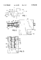
- FIG. 2 is a side elevational view of a cartridge valve and solenoid structure including functional elements corresponding to the diagrammatical representation of FIG. 1;
- FIG. 3 is a cutaway view of an envelope for the cartridge valve illustrated in FIG. 2, such as may be used in a manifold-based hydraulic circuit incorporating the valve of FIG. 2;
- FIG. 4 is a partial sectional view of the cartridge valve structure shown in FIG. 2 in a de-energized position
- FIG. 5 is a cutaway view of the valve shown in FIG. 4 in an energized and flowing position
- FIG. 6 is a cutaway view of the valve of FIGS. 4 and 5 in an energized position, wherein the check valve has been forced to its seat to prevent reverse flow through the directional control valve section;
- FIG. 7 is a perspective view of an end cap for the check valve section of the valve illustrated in the previous drawings for allowing flow to and from the actuator port and for centering the check valve ball;
- FIG. 8 is a sectional view through a section 8--8 of FIG. 4 illustrating the cap of FIG. 7 installed in the valve;
- FIG. 9 is a perspective view of an extension for the spool assembly of the valve illustrated in the previous drawings.
- FIG. 10 is a partial sectional view through line 10--10 of FIG. 4 depicting flow paths around an extension shown in FIG. 9 for evacuating fluid from the armature compartment of the valve.
- Valve 10 includes two envelope positions, a first envelope position 12 referred to hereinafter as the pressure position and a second envelope position 14 referred to hereinafter as the drain position.
- valve 10 is biased into the drain position 14 by means of a biasing spring 16 and can be actuated by energizing a solenoid 18 thereby shifting the valve to the pressure position 12.
- Valve 10 has three ports, including a pressure port 20, an actuator port 22 and a drain or tank port 24. In the pressure position 12, pressure port 20 is coupled through valve 10 to actuator port 22 and drain port 24 is blocked.
- Valve 10 further includes a check valve assembly 28 active in the pressure position for preventing reverse flow from actuator port 22 to pressure port 20 as described in greater detail below.
- FIG. 2 illustrates a presently preferred cartridge configuration for valve 10.
- valve 10 includes a solenoid coil assembly 29 and a cartridge valve body 30.
- Coil assembly 29 includes a coil housing 32 and a connector assembly 34 for applying power to the coil for shifting valve 10 between its operative positions.
- Valve body 30 includes three operative sections divided along its length, including an actuator section 36, a drain section 38 and a pressure section 40. Sections 36, 38 and 40 are isolated from one another by means of o-rings or similar sealing devices 42 fitted within appropriate grooves 44 between the relative sections.
- Cartridge valve body 30 is adapted for sealing engagement in a drilled and tapped envelope 46 as illustrated in FIG. 3.
- Envelope 46 is formed in a manifold structure 48 which may be independent of other valving or may be one of several envelopes interconnected in a larger circuit manifold structure in a manner well known in the art.
- Envelope 46 includes a series of lands 50 designed to contact and sealingly engage seals 42 on cartridge valve body 30 when body 30 is inserted and secured within envelope 46 such as by threaded engagement.
- envelope 46 is formed with fluid conduit regions 52 surrounding each of actuator, drain and pressure sections 36, 38 and 40 upon engagement of valve body 30 in envelope 46. In a manner well known in the art, regions 52 are plumbed internally in manifold 48 to channel pressurized fluid to and from ports 20, 22 and 24 of valve 10.
- FIGS. 4, 5 and 6 illustrate a partially sectioned view of valve 10 including the structures internal to cartridge valve body 30.
- valve 10 is shown in its drain position 14.
- FIGS. 5 and 6 illustrate valve 10 in its pressure position with two alternative positions of check valve assembly 28.
- coil assembly 29 includes an encapsulated solenoid coil, and envelopes an armature 56 received within a solenoid chamber 58 of housing 32. Armature 56 is biased within chamber 58 by biasing spring 16 to urge armature 56 to a biased position, preferably drain position 14.
- armature 56 is formed with a hollow center region 60 for receiving biasing spring 16. Center region 60 and the areas of solenoid chamber 58 not occupied by armature 56 or biasing spring 16 are flooded with fluid and communicate with the internal structure of valve body 30 as described below.
- Armature 56 is coupled to a spool assembly 62 within valve body 30 for shifting spool assembly 62 between the operative positions of valve 10.
- Spool assembly 62 includes a hollow spool 64 terminating on one end with an attachment button 66 and open on the opposite end 68.
- Spool assembly 62 further includes a plunger or extension 70 coupled to spool 64 by means of a connecting pin 72 received within aligned bores 74 and 76 of spool 64 and extension 70, respectively.
- spool 64 includes an area of reduced diameter 78. Area 78 is received within a slot 80 formed in an end of armature 56 such that attachment button 66 fits within a larger slot in armature 56 adjacent to slot 80.
- Slots 80 and 82 in armature 56 thus capture attachment button 66 and form abutment surfaces for contacting attachment button 66 for forcing spool 64 to slide within valve body 30 in response to biasing force from spring 16 or actuating (retracting) force from armature 56 upon energization of coil 54.
- Spool 64 is thus slidingly received within valve body 30 and includes a pair of lands 84 and 86 machined for close tolerance fit within valve body 30. Lands 84 and 86 are separated by an area of reduced diameter 88 through which a plurality of apertures 90 are formed for permitting flow through pressure port 20 or drain port 22, depending upon the position of spool 64 within valve body 30. Apertures 90 thus communicate fluidly between area of reduced diameter 88 and the interior 92 of spool 64.
- Check valve assembly 28 includes a seat 94 lodged within an enlarged end chamber 96 of valve body 30, a ball 98, a biasing spring 100 and a cap 102 fitted within enlarged end chamber 96.
- Cap 102 includes apertures 104 and internal guiding surfaces 106. Apertures 104 allow fluid to flow freely through check valve assembly 28, while guiding surfaces 106 guide ball 98 in its motion within assembly 28 as described in greater detail below.
- extension 70 of spool assembly 62 includes an elongated tapered portion 108 of sufficient length to extend through open end 68 of spool 64 and through a central aperture 110 of seat 94.
- biasing spring 16 which has a larger spring constant than biasing spring 100, urges armature 56 to the left, thereby urging extension 70 into contact with check ball 98 and unseating check ball 98.
- a fluid path is thereby opened between actuator section 36 and drain section 38, through check valve assembly 28 and the interior 92 of spool 64.
- the embodiment illustrated in FIG. 4 establishes a fluid flow path between drain port 24 and actuator port 22. Because land 86 of spool 64 overlies pressure port 20 in this position, pressure port 20 is effectively blocked.
- FIG. 5 illustrates an orientation of check valve assembly 28 in a condition where pressure at pressure port 20 exceeds pressure at actuator port 22.
- FIG. 7 illustrates a presently preferred configuration for cap 102 of check valve assembly 28.
- cap 102 includes an annular body 112 through which apertures 104 are formed.
- Body 112 has an outer surface 114 which is interference fit within enlarged end chamber 96 of valve body 30 during assembly of valve 10.
- Cap 102 terminates in an enlarged annular region 116 which is press fit within a corresponding opening within enlarged end chamber 96.
- Cap 102 also includes guide surfaces 106 between apertures 104 for loosely contacting ball 98 and for receiving biasing spring 100. Guide surfaces 106 thus contact ball 98 and maintain ball 98 centered within check valve assembly 28 during operation of valve 10.
- a central aperture 118 surrounding apertures 104 As shown in FIG. 8, a central aperture 118 surrounding apertures 104.
- spool 62 includes a fluid passage 120 (see FIGS. 4, 5 and 6) extending through attachment button 66 and area of reduced diameter 78 for permitting the passage of fluid to and from solenoid chamber 58.
- extension 70 includes an elongated passage 122 in the region of extension 70 coupled to spool 64, as shown in FIG. 9.
- Passage 122 is preferably formed as an elongated notch or groove extending from an end of extension 70 opposite tapered portion 108 and along the entire portion of extension 70 received within the closed end of spool 64.
- Bore 76 for receiving connecting pin 72 extends transversely to passage 122 as shown in FIG. 9.
- solenoid chamber 58 is in fluid communication with interior 92 of spool 64 as follows. Hollow center region 60 of armature 56 terminates at attachment button 66 and is in fluid communication with passage 120 of spool 64. Fluid from passage 120 is free to flow through groove 122 of extension 70 to the interior 92 of spool 64. Accordingly, as armature 56 is moved by energization of solenoid 54, fluid is evacuated from solenoid chamber 58 through hollow center region 60 and passages 120 and 122. Conversely, upon de-energization of solenoid 54, armature 56 is urged back into its biased position by spring 16 and fluid may re-enter solenoid chamber 58 through passages 122 and 120.
- FIG. 10 illustrates the location of groove 122 of extension 70 when valve 10 is assembled and installed in a manifold structure 48.
- valve 10 will be surrounded by a fluid conduit region 52 within manifold 48.
- Valve body 30, including passages for communicating fluid through spool 64, is centered within fluid conduit region 52 (passages illustrated in FIG. 10 being those associated with a pressure port 20).
- extension 70 is lodged with grooves 122 extending along spool 64 between the end of extension 70 and the interior of spool 64.
- extension 70 includes two identical grooves 122 formed at diametrically opposed locations on extension 70 for communicating fluid around extension 70 and between solenoid chamber 58 and the interior 92 of spool 64.
- valve 10 includes relatively few parts that can be assembled in a simple and straightforward manner.
- spool assembly 62 is first pre-assembled by attaching extension 70 within spool 64 by means of pin 72.
- Spool 64 is then coupled to armature 56 by inserting attachment button 66 into groove 82.
- Armature 56 and spool assembly 62 may then be inserted into housing 32 with spring 16 being positioned within hollow central region 60 of armature 56.
- Check valve assembly 28 is also pre-assembled within valve body 30 by inserting seat 94, ball 98, and spring 100 into a valve body 30 and pressing cap 102 into position.
- cap 102 may be threaded or otherwise attached into valve body 30, such as by a snap ring and groove structure.
- Valve body 30 is then assembled on housing 32 by sliding spool assembly 62 therethrough.
- Valve body 30 is secured to housing 32 by means of threaded engagement of corresponding surfaces of these two elements.
- armature 56 is free to slide within housing 32, bounded on one end by valve body 30 and on the other end by the base of solenoid chamber 58.
Abstract
Description
Claims (20)
Priority Applications (2)
| Application Number | Priority Date | Filing Date | Title |
|---|---|---|---|
| US08/694,559 US5738142A (en) | 1996-08-09 | 1996-08-09 | Pressure holding directional control valve |
| US08/808,018 US5904228A (en) | 1996-08-09 | 1997-03-03 | Brake control system and related method |
Applications Claiming Priority (1)
| Application Number | Priority Date | Filing Date | Title |
|---|---|---|---|
| US08/694,559 US5738142A (en) | 1996-08-09 | 1996-08-09 | Pressure holding directional control valve |
Related Child Applications (1)
| Application Number | Title | Priority Date | Filing Date |
|---|---|---|---|
| US08/808,018 Continuation-In-Part US5904228A (en) | 1996-08-09 | 1997-03-03 | Brake control system and related method |
Publications (1)
| Publication Number | Publication Date |
|---|---|
| US5738142A true US5738142A (en) | 1998-04-14 |
Family
ID=24789356
Family Applications (1)
| Application Number | Title | Priority Date | Filing Date |
|---|---|---|---|
| US08/694,559 Expired - Lifetime US5738142A (en) | 1996-08-09 | 1996-08-09 | Pressure holding directional control valve |
Country Status (1)
| Country | Link |
|---|---|
| US (1) | US5738142A (en) |
Cited By (32)
| Publication number | Priority date | Publication date | Assignee | Title |
|---|---|---|---|---|
| US5950673A (en) * | 1997-12-09 | 1999-09-14 | Joy Mm Delaware, Inc. | Valves |
| US6161618A (en) * | 1998-08-06 | 2000-12-19 | Dtc International, Inc. | Subsea control module |
| US6209563B1 (en) | 2000-01-07 | 2001-04-03 | Saturn Electronics & Engineering, Inc. | Solenoid control valve |
| US6247494B1 (en) * | 1999-03-05 | 2001-06-19 | Linde Aktiengesellschaft | Control valve device for a hydraulic user |
| US6321767B1 (en) | 2000-01-10 | 2001-11-27 | Saturn Electronics & Engineering, Inc. | High flow solenoid control valve |
| KR20020054181A (en) * | 2000-12-27 | 2002-07-06 | 이계안 | Hydraulic solenoid valve |
| US6431209B1 (en) * | 2000-03-16 | 2002-08-13 | Ross Operating Valve Company | Multi-pressure ball-poppet control valve |
| US6431207B1 (en) * | 2000-03-16 | 2002-08-13 | Ross Operating Valve Company | High-pressure ball-poppet control valve |
| US6581634B2 (en) | 2000-01-10 | 2003-06-24 | Saturn Electronics & Engineering, Inc. | Solenoid control valve with particle gettering magnet |
| US20040112208A1 (en) * | 2002-12-11 | 2004-06-17 | Kot Norbert J. | Pilot-operated check valve cartridge |
| US20040144938A1 (en) * | 2002-10-17 | 2004-07-29 | Frank Akselberg | Pressure compensated pilot operated check valve |
| US20050145813A1 (en) * | 2003-12-19 | 2005-07-07 | Kumar Viraraghavan S. | Solenoid valve assembly |
| US20050223885A1 (en) * | 2002-12-17 | 2005-10-13 | Nem S.P.A. | Controlled-flow hydraulic distributor |
| US20060097209A1 (en) * | 2004-11-09 | 2006-05-11 | Barron Luis F | Ball retainer for vehicle solenoid valve |
| US20070138422A1 (en) * | 2005-12-21 | 2007-06-21 | Saturn Electronics & Engineering, Inc. | Solenoid operated fluid control valve |
| US20070251499A1 (en) * | 2004-08-28 | 2007-11-01 | Alessandro De Luca | High-Pressure Pump for a Fuel Injection System of an Internal Combustion Engine |
| US20070284008A1 (en) * | 2006-06-13 | 2007-12-13 | Brower Brent J | Pressure regulating valve |
| US20080069712A1 (en) * | 2004-06-16 | 2008-03-20 | Michael Mennicken | High-Pressure Pump for a Fuel Injection System of an Internal Combustion Engine |
| US20080202760A1 (en) * | 2007-02-24 | 2008-08-28 | M.S.C.M. Limited | Subsea securing devices |
| US20090025803A1 (en) * | 2007-07-26 | 2009-01-29 | Georg Scherer | Valve |
| US20090166274A1 (en) * | 2007-05-24 | 2009-07-02 | Eaton Corporation | Engine valve with a combined engine oil filter and valve actuator solenoid |
| CN101446244B (en) * | 2008-12-17 | 2010-06-09 | 中国航天科技集团公司第六研究院第十一研究所 | Single-valve core double-channel solenoid valve |
| US20110088909A1 (en) * | 2009-09-09 | 2011-04-21 | Vetco Gray Controls Limited | Stabplate connections |
| CN102619800A (en) * | 2012-04-10 | 2012-08-01 | 大连海事大学 | Pure water piezoelectric ceramic driving switching valve |
| CN102619801A (en) * | 2012-04-10 | 2012-08-01 | 大连海事大学 | Pure-water bidirectional opposed piezoelectric ceramic reversing valve |
| CN101885327B (en) * | 2009-05-12 | 2013-04-17 | 宁波安捷制动器有限公司 | Hydraulic boost valve |
| US9816626B1 (en) | 2014-07-15 | 2017-11-14 | Davis & Davis Company | Method and device for adapting an actuator to a valve |
| US20180334153A1 (en) * | 2017-05-17 | 2018-11-22 | Mando Corporation | Valve assembly and anti-lock braking system including the same |
| CN110778553A (en) * | 2019-11-05 | 2020-02-11 | 武芳 | Load holding valve for engineering machinery oil cylinder |
| US10808735B2 (en) | 2018-09-21 | 2020-10-20 | Ford Global Technologies, Llc | Transmission park valve with steel saddle |
| US20210322706A1 (en) * | 2015-09-04 | 2021-10-21 | Fisher & Paykel Healthcare Limited | Connectors for conduits |
| WO2022001032A1 (en) * | 2020-06-30 | 2022-01-06 | 潍柴动力股份有限公司 | Load holding valve and hydraulic control system |
Citations (23)
| Publication number | Priority date | Publication date | Assignee | Title |
|---|---|---|---|---|
| US2868494A (en) * | 1954-08-26 | 1959-01-13 | United Aircraft Corp | Anti-vibrating solenoid valve |
| US3943824A (en) * | 1975-01-22 | 1976-03-16 | Deere & Company | Hydraulic system |
| US4088151A (en) * | 1976-05-26 | 1978-05-09 | Borg-Warner Corporation | Cylinder locking apparatus |
| US4569273A (en) * | 1983-07-18 | 1986-02-11 | Dynex/Rivett Inc. | Three-way proportional valve |
| US4620565A (en) * | 1985-09-03 | 1986-11-04 | Allied Corporation | Integrated three way and isolation solenoid valve |
| US4640391A (en) * | 1982-07-12 | 1987-02-03 | Akebono Brake Industry Company, Ltd. | Automatic stop valve device for vehicle brake systems |
| US4712767A (en) * | 1986-10-29 | 1987-12-15 | Allied Corporation | Solenoid control valve |
| US4765693A (en) * | 1986-03-08 | 1988-08-23 | Robert Bosch Gmbh | Valve assembly |
| US4859005A (en) * | 1986-07-26 | 1989-08-22 | Eaton Corporation | Three-port fluid valve |
| US4936344A (en) * | 1988-05-10 | 1990-06-26 | Bendix France | Pilot-controlled valve for a wheel anti-lock system |
| US4938545A (en) * | 1989-03-13 | 1990-07-03 | General Motors Corporation | ABS solenoid/isolation valve integration into single-ended solenoid body, using pump pressure actuation |
| US5076323A (en) * | 1989-11-16 | 1991-12-31 | Robert Bosch Gmbh | Electromagnetic valve |
| US5104091A (en) * | 1991-05-14 | 1992-04-14 | United Technologies Corporation | Spring assisted ball valve |
| US5118077A (en) * | 1991-08-09 | 1992-06-02 | Borg-Warner Automotive Electronic & Mechanical Systems Corporation | Pulse width modulated solenoid valve for variable displacement control |
| US5145148A (en) * | 1991-11-14 | 1992-09-08 | Siemens Automotive L.P. | Solenoid valve operating mechanism comprising a pin having a plastic sleeve molded onto a metal core |
| US5234030A (en) * | 1991-07-16 | 1993-08-10 | Bendix Europe Services Techniques | Pressure-regulating device for a hydraulic circuit |
| US5261731A (en) * | 1990-07-03 | 1993-11-16 | Nippondenso Co., Ltd. | ABS proportional valve capable of remaining open while the wheel cylinder drain valve is open |
| US5299859A (en) * | 1991-11-15 | 1994-04-05 | Allied-Signal Inc. | Combination solenoid valve and shuttle valve |
| US5333947A (en) * | 1991-06-27 | 1994-08-02 | Bendix Europe Services Techniques | Solenoid valve for a wheel antilockup system |
| US5358320A (en) * | 1992-02-28 | 1994-10-25 | Atsugi Unisia Corporation | Anti-skid brake control system for automotive vehicles |
| US5410943A (en) * | 1991-10-31 | 1995-05-02 | Alliedsignal Europe Services Techniques | Pressure regulation device for hydraulic system |
| US5458150A (en) * | 1993-06-03 | 1995-10-17 | Toyota Jidosha Kabushiki Kaisha | Solenoid valve device |
| US5467797A (en) * | 1994-12-23 | 1995-11-21 | General Motors Corporation | Two-position three-way solenoid valve |
-
1996
- 1996-08-09 US US08/694,559 patent/US5738142A/en not_active Expired - Lifetime
Patent Citations (23)
| Publication number | Priority date | Publication date | Assignee | Title |
|---|---|---|---|---|
| US2868494A (en) * | 1954-08-26 | 1959-01-13 | United Aircraft Corp | Anti-vibrating solenoid valve |
| US3943824A (en) * | 1975-01-22 | 1976-03-16 | Deere & Company | Hydraulic system |
| US4088151A (en) * | 1976-05-26 | 1978-05-09 | Borg-Warner Corporation | Cylinder locking apparatus |
| US4640391A (en) * | 1982-07-12 | 1987-02-03 | Akebono Brake Industry Company, Ltd. | Automatic stop valve device for vehicle brake systems |
| US4569273A (en) * | 1983-07-18 | 1986-02-11 | Dynex/Rivett Inc. | Three-way proportional valve |
| US4620565A (en) * | 1985-09-03 | 1986-11-04 | Allied Corporation | Integrated three way and isolation solenoid valve |
| US4765693A (en) * | 1986-03-08 | 1988-08-23 | Robert Bosch Gmbh | Valve assembly |
| US4859005A (en) * | 1986-07-26 | 1989-08-22 | Eaton Corporation | Three-port fluid valve |
| US4712767A (en) * | 1986-10-29 | 1987-12-15 | Allied Corporation | Solenoid control valve |
| US4936344A (en) * | 1988-05-10 | 1990-06-26 | Bendix France | Pilot-controlled valve for a wheel anti-lock system |
| US4938545A (en) * | 1989-03-13 | 1990-07-03 | General Motors Corporation | ABS solenoid/isolation valve integration into single-ended solenoid body, using pump pressure actuation |
| US5076323A (en) * | 1989-11-16 | 1991-12-31 | Robert Bosch Gmbh | Electromagnetic valve |
| US5261731A (en) * | 1990-07-03 | 1993-11-16 | Nippondenso Co., Ltd. | ABS proportional valve capable of remaining open while the wheel cylinder drain valve is open |
| US5104091A (en) * | 1991-05-14 | 1992-04-14 | United Technologies Corporation | Spring assisted ball valve |
| US5333947A (en) * | 1991-06-27 | 1994-08-02 | Bendix Europe Services Techniques | Solenoid valve for a wheel antilockup system |
| US5234030A (en) * | 1991-07-16 | 1993-08-10 | Bendix Europe Services Techniques | Pressure-regulating device for a hydraulic circuit |
| US5118077A (en) * | 1991-08-09 | 1992-06-02 | Borg-Warner Automotive Electronic & Mechanical Systems Corporation | Pulse width modulated solenoid valve for variable displacement control |
| US5410943A (en) * | 1991-10-31 | 1995-05-02 | Alliedsignal Europe Services Techniques | Pressure regulation device for hydraulic system |
| US5145148A (en) * | 1991-11-14 | 1992-09-08 | Siemens Automotive L.P. | Solenoid valve operating mechanism comprising a pin having a plastic sleeve molded onto a metal core |
| US5299859A (en) * | 1991-11-15 | 1994-04-05 | Allied-Signal Inc. | Combination solenoid valve and shuttle valve |
| US5358320A (en) * | 1992-02-28 | 1994-10-25 | Atsugi Unisia Corporation | Anti-skid brake control system for automotive vehicles |
| US5458150A (en) * | 1993-06-03 | 1995-10-17 | Toyota Jidosha Kabushiki Kaisha | Solenoid valve device |
| US5467797A (en) * | 1994-12-23 | 1995-11-21 | General Motors Corporation | Two-position three-way solenoid valve |
Cited By (47)
| Publication number | Priority date | Publication date | Assignee | Title |
|---|---|---|---|---|
| AU739640B2 (en) * | 1997-12-09 | 2001-10-18 | Joy Mm Delaware, Inc. | Valves |
| US5950673A (en) * | 1997-12-09 | 1999-09-14 | Joy Mm Delaware, Inc. | Valves |
| US6161618A (en) * | 1998-08-06 | 2000-12-19 | Dtc International, Inc. | Subsea control module |
| US6247494B1 (en) * | 1999-03-05 | 2001-06-19 | Linde Aktiengesellschaft | Control valve device for a hydraulic user |
| US6209563B1 (en) | 2000-01-07 | 2001-04-03 | Saturn Electronics & Engineering, Inc. | Solenoid control valve |
| US6581634B2 (en) | 2000-01-10 | 2003-06-24 | Saturn Electronics & Engineering, Inc. | Solenoid control valve with particle gettering magnet |
| US6321767B1 (en) | 2000-01-10 | 2001-11-27 | Saturn Electronics & Engineering, Inc. | High flow solenoid control valve |
| US6431207B1 (en) * | 2000-03-16 | 2002-08-13 | Ross Operating Valve Company | High-pressure ball-poppet control valve |
| US6431209B1 (en) * | 2000-03-16 | 2002-08-13 | Ross Operating Valve Company | Multi-pressure ball-poppet control valve |
| KR20020054181A (en) * | 2000-12-27 | 2002-07-06 | 이계안 | Hydraulic solenoid valve |
| US20040144938A1 (en) * | 2002-10-17 | 2004-07-29 | Frank Akselberg | Pressure compensated pilot operated check valve |
| US20040112208A1 (en) * | 2002-12-11 | 2004-06-17 | Kot Norbert J. | Pilot-operated check valve cartridge |
| US20050223885A1 (en) * | 2002-12-17 | 2005-10-13 | Nem S.P.A. | Controlled-flow hydraulic distributor |
| US7264019B2 (en) * | 2002-12-17 | 2007-09-04 | Nem S.P.A. | Controlled-flow hydraulic distributor |
| US20050145813A1 (en) * | 2003-12-19 | 2005-07-07 | Kumar Viraraghavan S. | Solenoid valve assembly |
| US7246787B2 (en) | 2003-12-19 | 2007-07-24 | Kumar Viraraghavan S | Solenoid valve assembly |
| US20080069712A1 (en) * | 2004-06-16 | 2008-03-20 | Michael Mennicken | High-Pressure Pump for a Fuel Injection System of an Internal Combustion Engine |
| US7571713B2 (en) * | 2004-08-28 | 2009-08-11 | Robert Bosch Gmbh | High-pressure pump for a fuel injection system of an internal combustion engine |
| US20070251499A1 (en) * | 2004-08-28 | 2007-11-01 | Alessandro De Luca | High-Pressure Pump for a Fuel Injection System of an Internal Combustion Engine |
| US20060097209A1 (en) * | 2004-11-09 | 2006-05-11 | Barron Luis F | Ball retainer for vehicle solenoid valve |
| US20070138422A1 (en) * | 2005-12-21 | 2007-06-21 | Saturn Electronics & Engineering, Inc. | Solenoid operated fluid control valve |
| US8371331B2 (en) | 2005-12-21 | 2013-02-12 | Saturn Electronics & Engineering, Inc. | Solenoid operated fluid control valve |
| US8733393B2 (en) | 2005-12-21 | 2014-05-27 | Flextronics Automotive Usa, Inc. | Solenoid operated fluid control valve |
| US8733395B2 (en) | 2005-12-21 | 2014-05-27 | Flextronics Automotive Usa, Inc. | Solenoid operated fluid control valve |
| US8127791B2 (en) * | 2005-12-21 | 2012-03-06 | Saturn Electronics & Engineering, Inc. | Solenoid operated fluid control valve |
| US8567755B2 (en) | 2005-12-21 | 2013-10-29 | Saturn Electronics & Engineering, Inc. | Solenoid operated fluid control valve |
| US20070284008A1 (en) * | 2006-06-13 | 2007-12-13 | Brower Brent J | Pressure regulating valve |
| US20080202760A1 (en) * | 2007-02-24 | 2008-08-28 | M.S.C.M. Limited | Subsea securing devices |
| US8011434B2 (en) * | 2007-02-24 | 2011-09-06 | M.S.C.M. Limited | Subsea securing devices |
| US20090166274A1 (en) * | 2007-05-24 | 2009-07-02 | Eaton Corporation | Engine valve with a combined engine oil filter and valve actuator solenoid |
| US20090025803A1 (en) * | 2007-07-26 | 2009-01-29 | Georg Scherer | Valve |
| US8230881B2 (en) * | 2007-07-26 | 2012-07-31 | Firma Svm Schultz Verwaltungs-Gmbh & Co. Kg | Valve |
| CN101446244B (en) * | 2008-12-17 | 2010-06-09 | 中国航天科技集团公司第六研究院第十一研究所 | Single-valve core double-channel solenoid valve |
| CN101885327B (en) * | 2009-05-12 | 2013-04-17 | 宁波安捷制动器有限公司 | Hydraulic boost valve |
| US8662181B2 (en) * | 2009-09-09 | 2014-03-04 | Vetco Gray Controls Limited | Stabplate connections |
| US20110088909A1 (en) * | 2009-09-09 | 2011-04-21 | Vetco Gray Controls Limited | Stabplate connections |
| CN102619801A (en) * | 2012-04-10 | 2012-08-01 | 大连海事大学 | Pure-water bidirectional opposed piezoelectric ceramic reversing valve |
| CN102619800A (en) * | 2012-04-10 | 2012-08-01 | 大连海事大学 | Pure water piezoelectric ceramic driving switching valve |
| CN102619801B (en) * | 2012-04-10 | 2014-10-29 | 大连海事大学 | Pure-water bidirectional opposed piezoelectric ceramic reversing valve |
| US9816626B1 (en) | 2014-07-15 | 2017-11-14 | Davis & Davis Company | Method and device for adapting an actuator to a valve |
| US20210322706A1 (en) * | 2015-09-04 | 2021-10-21 | Fisher & Paykel Healthcare Limited | Connectors for conduits |
| US20180334153A1 (en) * | 2017-05-17 | 2018-11-22 | Mando Corporation | Valve assembly and anti-lock braking system including the same |
| US11066054B2 (en) * | 2017-05-17 | 2021-07-20 | Mando Corporation | Valve assembly and anti-lock braking system including the same |
| US10808735B2 (en) | 2018-09-21 | 2020-10-20 | Ford Global Technologies, Llc | Transmission park valve with steel saddle |
| CN110778553A (en) * | 2019-11-05 | 2020-02-11 | 武芳 | Load holding valve for engineering machinery oil cylinder |
| CN110778553B (en) * | 2019-11-05 | 2021-07-09 | 山东金利液压科技有限公司 | Load holding valve for engineering machinery oil cylinder |
| WO2022001032A1 (en) * | 2020-06-30 | 2022-01-06 | 潍柴动力股份有限公司 | Load holding valve and hydraulic control system |
Similar Documents
| Publication | Publication Date | Title |
|---|---|---|
| US5738142A (en) | Pressure holding directional control valve | |
| US5474106A (en) | Solenoid valve for hydraulic brake units with slip control | |
| EP0323037B1 (en) | Solenoid valve assembly | |
| US4620565A (en) | Integrated three way and isolation solenoid valve | |
| EP0503188A2 (en) | Bidirectional cartridge valve | |
| US5002344A (en) | Fluid pressure controller for antilock brake control device | |
| US6851350B2 (en) | Valve device for a control cylinder | |
| US5467797A (en) | Two-position three-way solenoid valve | |
| US6814103B2 (en) | Solenoid valve, in particular, a pressure control valve | |
| JPH0146749B2 (en) | ||
| EP0227209B2 (en) | Pilot valves for two-stage hydraulic devices | |
| JPH06193750A (en) | Hydraulic valve device | |
| US6481452B2 (en) | High pressure, high flow pump prime valve | |
| JPH1081219A (en) | Hydraulic control valve gear in hydraulic braking device | |
| JP2567473B2 (en) | Flow control valve for vehicle antilock device | |
| CA1195206A (en) | Electrohydraulic valve | |
| US5904228A (en) | Brake control system and related method | |
| JPH0251682A (en) | Safety valve | |
| US5613519A (en) | Operating valve assembly with pressure compensation valve | |
| JPH01295083A (en) | Pressure limiting valve | |
| JPH1163288A (en) | Hydraulic pressure control valve device | |
| US5778929A (en) | Directional control valve assembly having a pressure compensation valve | |
| US6827102B2 (en) | Three port-two way solenoid valve | |
| KR100553657B1 (en) | Electromagnetic valve apparatus | |
| US5749225A (en) | Hydraulic systems and valve assemblies |
Legal Events
| Date | Code | Title | Description |
|---|---|---|---|
| AS | Assignment |
Owner name: CASE CORPORATION, WISCONSIN Free format text: ASSIGNMENT OF ASSIGNORS INTEREST;ASSIGNORS:EIKE, CRAIG R.;STOEVER, GUY T.;REEL/FRAME:008136/0305 Effective date: 19960730 |
|
| STCF | Information on status: patent grant |
Free format text: PATENTED CASE |
|
| FPAY | Fee payment |
Year of fee payment: 4 |
|
| AS | Assignment |
Owner name: CNH AMERICA LLC, PENNSYLVANIA Free format text: ASSIGNMENT OF ASSIGNORS INTEREST;ASSIGNOR:CASE CORPORATION;REEL/FRAME:014981/0944 Effective date: 20040805 |
|
| FPAY | Fee payment |
Year of fee payment: 8 |
|
| AS | Assignment |
Owner name: CNH AMERICA LLC, PENNSYLVANIA Free format text: ASSIGNMENT OF ASSIGNORS INTEREST;ASSIGNOR:CNH AMERICA LLC;REEL/FRAME:017766/0484 Effective date: 20060606 Owner name: BLUE LEAF I.P., INC., DELAWARE Free format text: ASSIGNMENT OF ASSIGNORS INTEREST;ASSIGNOR:CNH AMERICA LLC;REEL/FRAME:017766/0484 Effective date: 20060606 |
|
| FPAY | Fee payment |
Year of fee payment: 12 |