US5738454A - Multiple-function printer with common output path mechanism with floating guide ribs to accommodate media and documents of different thickness - Google Patents
Multiple-function printer with common output path mechanism with floating guide ribs to accommodate media and documents of different thickness Download PDFInfo
- Publication number
- US5738454A US5738454A US08/724,642 US72464296A US5738454A US 5738454 A US5738454 A US 5738454A US 72464296 A US72464296 A US 72464296A US 5738454 A US5738454 A US 5738454A
- Authority
- US
- United States
- Prior art keywords
- printed media
- documents
- guide ribs
- chassis
- exit
- Prior art date
- Legal status (The legal status is an assumption and is not a legal conclusion. Google has not performed a legal analysis and makes no representation as to the accuracy of the status listed.)
- Expired - Lifetime
Links
Images


Classifications
-
- H—ELECTRICITY
- H04—ELECTRIC COMMUNICATION TECHNIQUE
- H04N—PICTORIAL COMMUNICATION, e.g. TELEVISION
- H04N1/00—Scanning, transmission or reproduction of documents or the like, e.g. facsimile transmission; Details thereof
- H04N1/00567—Handling of original or reproduction media, e.g. cutting, separating, stacking
- H04N1/0057—Conveying sheets before or after scanning
- H04N1/00588—Conveying sheets before or after scanning to the scanning position
-
- B—PERFORMING OPERATIONS; TRANSPORTING
- B41—PRINTING; LINING MACHINES; TYPEWRITERS; STAMPS
- B41J—TYPEWRITERS; SELECTIVE PRINTING MECHANISMS, i.e. MECHANISMS PRINTING OTHERWISE THAN FROM A FORME; CORRECTION OF TYPOGRAPHICAL ERRORS
- B41J11/00—Devices or arrangements of selective printing mechanisms, e.g. ink-jet printers or thermal printers, for supporting or handling copy material in sheet or web form
- B41J11/0005—Curl smoothing, i.e. smoothing down corrugated printing material, e.g. by pressing means acting on wrinkled printing material
-
- B—PERFORMING OPERATIONS; TRANSPORTING
- B41—PRINTING; LINING MACHINES; TYPEWRITERS; STAMPS
- B41J—TYPEWRITERS; SELECTIVE PRINTING MECHANISMS, i.e. MECHANISMS PRINTING OTHERWISE THAN FROM A FORME; CORRECTION OF TYPOGRAPHICAL ERRORS
- B41J13/00—Devices or arrangements of selective printing mechanisms, e.g. ink-jet printers or thermal printers, specially adapted for supporting or handling copy material in short lengths, e.g. sheets
- B41J13/10—Sheet holders, retainers, movable guides, or stationary guides
- B41J13/103—Sheet holders, retainers, movable guides, or stationary guides for the sheet feeding section
-
- B—PERFORMING OPERATIONS; TRANSPORTING
- B41—PRINTING; LINING MACHINES; TYPEWRITERS; STAMPS
- B41J—TYPEWRITERS; SELECTIVE PRINTING MECHANISMS, i.e. MECHANISMS PRINTING OTHERWISE THAN FROM A FORME; CORRECTION OF TYPOGRAPHICAL ERRORS
- B41J13/00—Devices or arrangements of selective printing mechanisms, e.g. ink-jet printers or thermal printers, specially adapted for supporting or handling copy material in short lengths, e.g. sheets
- B41J13/10—Sheet holders, retainers, movable guides, or stationary guides
- B41J13/106—Sheet holders, retainers, movable guides, or stationary guides for the sheet output section
-
- B—PERFORMING OPERATIONS; TRANSPORTING
- B65—CONVEYING; PACKING; STORING; HANDLING THIN OR FILAMENTARY MATERIAL
- B65H—HANDLING THIN OR FILAMENTARY MATERIAL, e.g. SHEETS, WEBS, CABLES
- B65H3/00—Separating articles from piles
- B65H3/02—Separating articles from piles using friction forces between articles and separator
- B65H3/06—Rollers or like rotary separators
- B65H3/0661—Rollers or like rotary separators for separating inclined-stacked articles with separator rollers above the stack
-
- B—PERFORMING OPERATIONS; TRANSPORTING
- B65—CONVEYING; PACKING; STORING; HANDLING THIN OR FILAMENTARY MATERIAL
- B65H—HANDLING THIN OR FILAMENTARY MATERIAL, e.g. SHEETS, WEBS, CABLES
- B65H3/00—Separating articles from piles
- B65H3/44—Simultaneously, alternately, or selectively separating articles from two or more piles
-
- H—ELECTRICITY
- H04—ELECTRIC COMMUNICATION TECHNIQUE
- H04N—PICTORIAL COMMUNICATION, e.g. TELEVISION
- H04N1/00—Scanning, transmission or reproduction of documents or the like, e.g. facsimile transmission; Details thereof
- H04N1/00567—Handling of original or reproduction media, e.g. cutting, separating, stacking
- H04N1/0057—Conveying sheets before or after scanning
- H04N1/00591—Conveying sheets before or after scanning from the scanning position
-
- H—ELECTRICITY
- H04—ELECTRIC COMMUNICATION TECHNIQUE
- H04N—PICTORIAL COMMUNICATION, e.g. TELEVISION
- H04N1/00—Scanning, transmission or reproduction of documents or the like, e.g. facsimile transmission; Details thereof
- H04N1/00567—Handling of original or reproduction media, e.g. cutting, separating, stacking
- H04N1/0057—Conveying sheets before or after scanning
- H04N1/00596—Conveying sheets before or after scanning using at least a part of the apparatus in common for transporting to or from a plurality of scanning positions, e.g. for reading and printing
-
- H—ELECTRICITY
- H04—ELECTRIC COMMUNICATION TECHNIQUE
- H04N—PICTORIAL COMMUNICATION, e.g. TELEVISION
- H04N1/00—Scanning, transmission or reproduction of documents or the like, e.g. facsimile transmission; Details thereof
- H04N1/00567—Handling of original or reproduction media, e.g. cutting, separating, stacking
- H04N1/0057—Conveying sheets before or after scanning
- H04N1/00599—Using specific components
- H04N1/00602—Feed rollers
-
- H—ELECTRICITY
- H04—ELECTRIC COMMUNICATION TECHNIQUE
- H04N—PICTORIAL COMMUNICATION, e.g. TELEVISION
- H04N1/00—Scanning, transmission or reproduction of documents or the like, e.g. facsimile transmission; Details thereof
- H04N1/00567—Handling of original or reproduction media, e.g. cutting, separating, stacking
- H04N1/0062—Removing sheets from a stack or inputting media
- H04N1/00623—Selectively inputting media from one of a plurality of input sources, e.g. input trays
-
- H—ELECTRICITY
- H04—ELECTRIC COMMUNICATION TECHNIQUE
- H04N—PICTORIAL COMMUNICATION, e.g. TELEVISION
- H04N1/00—Scanning, transmission or reproduction of documents or the like, e.g. facsimile transmission; Details thereof
- H04N1/00567—Handling of original or reproduction media, e.g. cutting, separating, stacking
- H04N1/00628—Separating, e.g. preventing feeding of two sheets at a time
-
- B—PERFORMING OPERATIONS; TRANSPORTING
- B65—CONVEYING; PACKING; STORING; HANDLING THIN OR FILAMENTARY MATERIAL
- B65H—HANDLING THIN OR FILAMENTARY MATERIAL, e.g. SHEETS, WEBS, CABLES
- B65H2301/00—Handling processes for sheets or webs
- B65H2301/40—Type of handling process
- B65H2301/42—Piling, depiling, handling piles
- B65H2301/423—Depiling; Separating articles from a pile
- B65H2301/4232—Depiling; Separating articles from a pile of horizontal or inclined articles, i.e. wherein articles support fully or in part the mass of other articles in the piles
- B65H2301/42328—Depiling; Separating articles from a pile of horizontal or inclined articles, i.e. wherein articles support fully or in part the mass of other articles in the piles of inclined articles and inclination angle >45
-
- H—ELECTRICITY
- H04—ELECTRIC COMMUNICATION TECHNIQUE
- H04N—PICTORIAL COMMUNICATION, e.g. TELEVISION
- H04N1/00—Scanning, transmission or reproduction of documents or the like, e.g. facsimile transmission; Details thereof
- H04N1/04—Scanning arrangements, i.e. arrangements for the displacement of active reading or reproducing elements relative to the original or reproducing medium, or vice versa
- H04N1/12—Scanning arrangements, i.e. arrangements for the displacement of active reading or reproducing elements relative to the original or reproducing medium, or vice versa using the sheet-feed movement or the medium-advance or the drum-rotation movement as the slow scanning component, e.g. arrangements for the main-scanning
-
- H—ELECTRICITY
- H04—ELECTRIC COMMUNICATION TECHNIQUE
- H04N—PICTORIAL COMMUNICATION, e.g. TELEVISION
- H04N1/00—Scanning, transmission or reproduction of documents or the like, e.g. facsimile transmission; Details thereof
- H04N1/04—Scanning arrangements, i.e. arrangements for the displacement of active reading or reproducing elements relative to the original or reproducing medium, or vice versa
- H04N1/19—Scanning arrangements, i.e. arrangements for the displacement of active reading or reproducing elements relative to the original or reproducing medium, or vice versa using multi-element arrays
- H04N1/191—Scanning arrangements, i.e. arrangements for the displacement of active reading or reproducing elements relative to the original or reproducing medium, or vice versa using multi-element arrays the array comprising a one-dimensional array, or a combination of one-dimensional arrays, or a substantially one-dimensional array, e.g. an array of staggered elements
- H04N1/192—Simultaneously or substantially simultaneously scanning picture elements on one main scanning line
- H04N1/193—Simultaneously or substantially simultaneously scanning picture elements on one main scanning line using electrically scanned linear arrays, e.g. linear CCD arrays
Definitions
- This invention relates generally to printers and facsimile devices, and more particularly to printers and facsimile devices and their operation which are combined together to form a multiple-function product.
- Facsimile devices i.e., fax machines
- a conventional fax machine is used for three separate functions: sending a first document; receiving a second document; and producing a hardcopy printout of the second document.
- the hardcopy printout is not the actual second document but rather a close facsimile thereof.
- An enhanced fax machine can also be used to perform two additional functions: producing a hardcopy printout of the first document; and producing a hardcopy printout of a cumulative report showing an itemized listing of date, time, and destination for first documents sent from the fax machine.
- a fax machine acts primarily as both a sender (i.e., scanning and transmitting) and receiver of documents, and that the fax machine also acts secondarily as a printer (i.e., printing a facsimile of a second document, printing a copy of a scanned first document, or printing an itemized report) and secondarily as a convenience copier (i.e., scanning/printing a first document).
- a printer i.e., printing a facsimile of a second document, printing a copy of a scanned first document, or printing an itemized report
- a convenience copier i.e., scanning/printing a first document
- Both the basic fax machine and the enhanced fax machine just described have used two separate paper paths.
- One path is dedicated to the first document and typically includes document feeder tray, document paper pick/paper drive system, document scanning station, and document output.
- Another path is dedicated to the printout (originally roll-fed, now sheet-fed) and typically includes sheet feeder tray, sheet paper pick/sheet drive system, sheet printing station, and sheet output.
- a fax machine is a bulky, expensive multiple-function device which requires a large number of parts for duplicate paper handling functions.
- Another important object is to provide a multiple-function printer/fax machine which is primarily a printer peripheral for a computer as well as primarily a fax machine, having integrated shared paper path and common mechanisms for scanning documents on the one hand and for producing hardcopy printout sheets on the other hand.
- Still another object is to provide a multiple-function printer/fax machine with a pressure plate feeder scheme which will enable fast reliable automatic feeding of a large stack of documents up to about twenty-five pages as well as a large stack of printout sheets up to about one hundred pages.
- a related object is to provide dual feeder paths into a common paper pick, with self-actuating shifting means for automatically changing from a printing mode to a scanning mode whenever a document is placed in an automatic document feeder tray.
- a further object is to provide a multiple function machine having a single drive motor for picking individual pages from a stack and for moving individual pages past each processing station such as a scanning station and/or a printing station.
- a related object is to provide gear means from the single drive motor for driving a primary drive roller, a paper pick roller, and an output roller at different rates, and for moving a feeder pressure plate to and fro between positions of engagement and disengagement.
- An additional object is to provide the aforementioned multiple function machine with a self-actuating delay mechanism for spacing apart individual pages which are sequentially picked from a document stack or a printout sheet stack.
- the common document/sheet path and shared mechanisms include a pressure plate, pick roller assembly, drive roller system, and drive motor wherein documents proceed actively through a scanner station and passively through a printer station and printout sheets proceed passively through the scanner station and actively through the printer station, both to a common output.
- the common document/sheet path and shared mechanisms include a drive roller system and output, wherein documents proceed actively through a scanner station and passively through a printer station and printout sheets bypass the scanner station and proceed actively through the printer station, both to a common output.
- the common document/sheet path and shared mechanisms include a common path through a main drive roller system, a combined scanner/printer station and output, with separate pick rollers and separate pressure plates driven by the drive motor for the main drive roller system.
- Sheet media for printing is typically in good form and does not always require a paper path constraint on both faces of the paper.
- a translating carriage type printer i.e. typical inkjet printer
- the space above the paper in the printing region is used for moving the print cartridge across the paper in close proximity.
- Documents for scanning can be in bad form and have been found to require top and bottom face constraint throughout the paper path.
- this invention includes a means to constrain both faces of documents which pass through the print region and when printing on original sheet stock does not interfere with the print cartridge.
- This improvement includes floating guide ribs which coupled with conical wheels in a common paper path exit mechanism that forces printed media to be driven out in a conical shape at an outward angle for wet stacking, as well as to allow relatively thicker documents to be driven out of the printer in the same paper path.
- the floating guide ribs which are pivotable with respect to an exit chassis provides a vertical constraint on the wet printed media as the media exits from a row of star wheels onto the conical wheels (often times called "tires"). These ribs, in conjunction with the conical wheels, forces the wet media to exit into a conical shape and at an upward angle. This prevents the exiting sheet from smearing into the drying media sitting in the output tray.
- This improvement is used in conjunction with a document guide located above the paper path in the printing area which guides the document into the output roller nip.
- the document guides allows for deformed documents to be reliably moved through a common paper path multi-function printer. This results in a lower cost multi-function printer without compromising the reliability of the document feeding function.
- the present invention includes a common printer platen for conveying printed media and documents to a printer exit and a series of spaced guide ribs extending from the platen and wherein the guide ribs are floating relative to the platen to accommodate printed media of a first range of thickness and documents of a second range of greater thickness.
- the printer exit mechanism includes an exit chassis, the chassis including a longitudinal first edge, a series of spaced guide ribs including an integral beam forming a star wheel carrier pivotably mounted adjacent to the chassis first edge, a series of equally spaced stops extending from the chassis and spring members extending between the chassis and the beams for urging the beams against the stops, whereby printed media of one thickness and documents of a greater thickness conveyed past the beams are accommodated by pivoted movement of the beams away from the stops.
- FIG. 1 is a schematic side view of a presently preferred printer/facsimile embodiment of the present invention
- FIG. 2 is a functional block diagram of the embodiment of FIG. 1;
- FIG. 3 is an isometric view looking down into an implementation of the embodiment of FIG. 1;
- FIG. 4 is a fragmentary isometric view showing the input feeder slots and pick roller portion of FIG. 3;
- FIG. 5 is a front isometric view of FIG. 3;
- FIG. 6 is a side view of FIG. 3;
- FIG. 7 is a fragmentary back view looking up at the feeder slots and pick roller portion of FIG. 4;
- FIG. 8 is a close-up schematic showing a pick roller ready to begin a reverse rotation kicking partially picked sheet(s) backward into the ASF as a result of a document stack being inserted into the ADF;
- FIG. 9 is a close-up schematic showing the pressure plate in disengaged position and all of the partially picked sheets expelled from underneath the pick roller into the ASF;
- FIG. 10 is a close-up schematic showing the pressure plate returned to an engaged position with the pick roller already commencing to pick a page from the top of the stack of documents which now partially overly the stack of print sheets;
- FIG. 11 is a schematic side view of an alternate printer/facsimile embodiment of the present invention.
- FIG. 12 is a functional block diagram of the embodiment of FIG. 11.
- FIG. 13 is a functional block diagram of another alternate printer/facsimile embodiment of the present invention.
- FIG. 14 is a more detailed schematic side view of the common paper path of the invention illustrating the common path with a curled document positioned immediately prior to an incipient paper jam at the output roller nip;
- FIG. 15 is a schematic side view of the common paper path showing a jam-preventing document guide in a lowered position
- FIG. 16 is a schematic side view of the common paper path showing the document guide in a raised position allowing the print cartridge to be horizontally moved into a printing mode position;
- FIG. 17 is a top view of the printer station with the document guide in a scanning mode position.
- FIG. 18 is a cross-sectioned side view of the exit mechanism including a floating rib and beam.
- FIG. 19 is an exploded view of the exit chassis with floating guide rib including a star wheel carrier.
- FIG. 20 is an exploded view of the document deflector of FIG. 17 and showing a series of floating ribs and star wheels assembled in the exit chassis.
- FIG. 21 is an exploded view of the rear of the exit chassis and conical wheels downstream from the floating ribs and star wheels.
- FIG. 22 is a exploded view of the guide ribs and star wheel carrier.
- FIG. 23 is a perspective view of the assembled star wheel carrier and guide ribs.
- FIG. 24 is a perspective view of the underside of the exit chassis with an attached document deflector and its drive mechanism.
- the invention provides for picking pages from a stack of sheets in an input feeder for roller-driven movement along a first path through a printing station to an output, and for picking pages from a stack of documents in an input feeder for roller-driven movement along a second path through a scanning station to an output.
- first and second paths are commonly shared, and common mechanisms are used for various steps such as for picking, providing roller-driven movement through the processing stations, and for actuating a pressure plate in the input feeders.
- the multiple-function device of the presently preferred embodiment includes a frame 20 for housing a scanner station 22 and a printer station 24.
- a stack of print sheets is loadable into an automatic sheet feeder (ASF) 26, and a stack of documents having text/graphics to be scanned is loadable into an automatic document feeder (ADF) 28 which together form a common input feeder slot 30 having a pick roller 32 and a spring-loaded stripper pad 33 at the lower end.
- the upper portion of the input feeder slot which constitutes the ADF is separated from the ASF by a divider 35.
- the divider is truncated at its lower end to allow document stacks and sheets stacks to converge at the pick roller (see FIGS. 8-10).
- a pressure plate 34 is attached at its upper end through pivot pin 36 to the frame and is normally biased upwardly against the pick roller by springs 38.
- a drive motor 40 is connected through a gear mechanism to the pressure plate 34 and pick roller 32 as described in more detail hereinafter, and is also connected to a main drive roller 42 which pulls the pages through the processing stations for either scanning or printing.
- the printout pages as well as the scanned pages pass across an output roller 43 to be deposited in a common output area 44.
- scanner station 22 includes a lamp 46 for illuminating a scanning zone, reflective mirrors 48, 50, a lens 49, and a CCD (charge-coupled device) photosensor 51.
- Printer station 24 includes inkjet cartridge 52 which rides on a slider rod 54 back and forth across a print zone.
- the common document/sheet path and shared mechanisms are similar to FIGS. 1-2 and include scanner station 22a, printer station 24, drive motor 40, main drive roller 42, output roller 43 and a shared output 44 wherein document pages proceed actively through the scanner station and passively through the printer station, and printout sheet pages bypass the scanner station and proceed actively through the printer station, both to a common output.
- ADF 60 has its own pivotally mounted spring-loaded pressure plate 62 to facilitate reliable page feeding to document pick roller 63
- ASF 64 has its own pivotally mounted spring-loaded pressure plate 66 to facilitate reliable page feeding to sheet pick roller 67, with both pick rollers 65, 67 being driven by the drive motor 40.
- FIG. 13 the common document/sheet path and shared mechanisms are similar to FIGS. 11-12. But this alternate embodiment provides a common path through a combined scanner/printer station 68 to a common output 44, with separate pick rollers 65, 67 and separate pressure plates 62a, 66a driven by the drive motor 40 for the main drive roller system.
- the input feeder slot is integrated into the device so that when the unit is resting with its feet 69 on a desk top, stacks of sheets or documents can be added without having to remove any tray. Since the frame is supported by legs 71 so that the input feeder slot is angled downwardly, both of the stacks naturally settle to the bottom of the slot so that the leading edges of pages on top of the stacks will impinge against the pick roller (see FIGS. 8-10). The action of the pressure plate against both stacks assures proper separation by the spring-loaded stripper pad 33 in combination with the rotation of the pick roller 32.
- the ADF includes an extender 70 mounted on the upper end of the divider 35 which pivots forwardly out of the way when pages are added or removed from the ASF.
- the ASF is sandwiched between the ADF and the bottom of the feeder slot and includes its own extender 72 as well as a single adjustable guide 74 for maintaining the sheet stack in proper positioning for feeding into the pick roller.
- the pick roller 32 is mounted on a pick shaft 78 which has a pair of guide rollers 80 also mounted thereon in the commonly shared paper path, as well as a double-pin delay coupler 81 mounted on the shaft end outside the frame.
- the guide rollers 80 and matching pinch rollers 82 help to hold the pages in proper position as they move past the pick roller to the scanning and printing stations.
- a unique gear mechanism is shown in FIGS. 3 and 6-7 for automatically moving the pressure plate to and fro between a disengaged position "open” position and an engaged “closed” position.
- the disengaged open position allows access to the stacks for removal, replenishment, or replacement of pages as well as for realignment of the stacks between one or more page picking events if that is deemed to be desirable and necessary to avoid mis-feeds. More importantly from a multiple-function point of view (see FIGS. 8-10), the disengaged open position allows new pages of documents to be placed in the ADF with their leading edges resting on top of the sheet stack in the ASF, thereby preparing for a scanning operation to commence.
- the engaged closed position holds the sheet stack in aligned position together as a unit if there are not any documents in the ADF. This helps to prevent more than one page from being accidently picked.
- the engaged closed position holds the document stack in aligned position together as a unit if there are not any sheets in the ASF. If there is already a stack of sheets in the ASF and some additional document pages have been added to the ADF, then the engaged closed position holds both the document stack and the underlying sheet stack in aligned position together as a composite stack insofar as their leading edges are concerned.
- FIG. 6 shows the gear mechanism in a "start disengagement" position, with motor drive gear 84 moving in reverse direction to cause main drive roller 42 to also go in reverse.
- Coupling pin 85 on linkage gear 104 is partway between forward direction coupling pin 87 and rearward direction coupling pin 89 on delay coupler 81. This assures that commencing the reverse driving of the pick roller to expel partially picked pages does not occur until after the pressure plate has been moved into disengagement position.
- Cam follower 86 is resting in a notch on cam 88 which is rigidly mounted for turning with pressure plate gear 90. So long as cam follower 86 remains in the notch, the pressure plate remains in closed engagement position.
- the connection between cam follower 86 and the pressure plate is best shown in FIG. 7.
- the cam follower 86 is mounted on the end of a pivot rod 92 which is mounted for pivotal rotation by a pair of brackets 94 and a counter-bracket 96.
- a pair of fingers 98 are also mounted on pivot rod 92 and interconnect with matching slots 99 so that when the pressure plate gear 90 is rotated in direction 100, the cam follower is forced to pivot upwardly into "disengagement position" and ride along the larger diameter surface 102.
- a linkage gear 104 is slidably mounted on the pick shaft 78 to couple the drive motor 40 to the pressure plate gear 90, and also to couple the drive motor 40 through the double-pin delay coupler 81 to the pick roller.
- the linkage gear rotates in direction 105 to move its attached transfer gear 106 into link position with the pressure plate gear 86.
- the coupling from drive motor 40 to the pressure plate gear 90 is through double-wheel gear 108, main drive gear 42, spur gears 110, 112, linkage gear 104, and transfer gear 106.
- Decoupling occurs when the motor drive gear 84 changes back to forward, since this changes the rotation direction of linkage gear 104 and moves transfer gear 106 in the direction 114 to a non-link position 116.
- the foregoing gear/cam mechanism provides for automatic movement of the pressure plate between a position of engagement of the stacks with the pick roller and a position of dis-engagement. This necessarily occurs after a page being processed at the scanning station or the printing station has passed by the main drive roller 42 and the output roller 43 to the common output area 44.
- the initiation of the dis-engagement can be programmed to occur at predetermined times such as before every picking step, or whenever a mis-feed occurs, or the like. Also, when a document page is placed in the ADF, it pushes down sensor 118 to activate the aforementioned dis-engagement sequence of steps.
- the delayed contact of the pin 85 on linkage gear 104 with double-pin delay coupler 81 causes the reversing of the pick roller expelling any pages from a previous picking step to occur after the pressure plate has moved to a position of dis-engagement.
- the gearing mechanism is designed to automatically provide a delay between the picking of successive pages from the sheet stack or document stack.
- the gearing ratios provide for output roller 43 to rotate faster than main drive roller 42 which rotates faster than pick roller 32.
- the speed differential between the output roller 43 and the main drive roller 42 keeps a page in tension as it passed through the printing station, the scanning station, or the combined printing/scanning station.
- the linkage gear 104 has its single pin 85 which engages one or the other of the two pins 87, 89 on the delay coupler 81 (depending on the direction of the main drive) to drive the pick roller forwardly or rearwardly with a partial revolution delay for driving the pick roller when a directional change occurs.
- This relationship between the linkage gear 104 and the delay coupler 81 when combined with the speed differential between the pick roller 32 and the main drive roller 42, provides for the pin on the linkage gear 104 to walk away from engagement of the pin on the delay coupler so long as a page is in driving engagement with both the pick roller and the main drive roller. In other words, during that double driving period, the pick roller is slaved to the paper and rotates faster than the linkage gear to cause the aforesaid "walk away".
- the aforementioned features of the present invention provide for automated operation of a printing station, scanning station or the like from a single drive motor through a gear mechanism which provides spaced-apart picking of successive pages from an input feed stack. These aforementioned features also provide for the shared use of a paper path and mechanisms which are involved along the path by a multiple-function device which employs operations such as printing, scanning and the like in the same machine.
- FIG. 14 illustrates the curling of a document 200 after the document has been fed from a document feeder 201 past a scanning station 202 where it has been scanned, passively over a printing station 203 (sans print cartridge which has slid away from the print zone) which document was destined to be conducted into a nip 204 between output rollers 205 and 206.
- a printing station 203 sans print cartridge which has slid away from the print zone
- FIG. 15 shows the addition of a document guide 210 which in a lowered position deflects an incoming document 200 by being forced by roller 216 under the deflector guide.
- the leading edge of a curled or damaged or deformed document (or the uncurled leading edge if the document is flat) are deflected by a document guide essentially smoothed-faced underside surface 217 and thus guide the leading edge 200b of the document into the nip 204.
- a tab 219 depends from near a distal end of guide 210 and rides on an edge of the print platen 203a (FIG. 16) of the printing station and functions as a down stop of the document guide 210.
- the document guide has a first long portion 213 which in a scanning mode position is parallel to the platen of the printing station and in position to guide a document (curled or uncurled) into the nip 204, an integral short portion 211 and a pivot 212.
- Arrow 220 in FIG. 17 denotes the document feed direction.
- the documents are constrained at their top surface by the underside 217 of the document guide and at their bottom surface by the print station platen.
- Sheets which are to be printed on are clean virgin sheets without curl and thus there is no need to guide or constrain the print sheets to the common output nip.
- Sensors (not shown) in the document tray 201 and in the sheet feed path 199 indicate if a document is to be scanned or a sheet is to be printed.
- Conical rollers 218 are provided as part of a wet paper stacker (shown in FIGS. 18-22) which functions to force the edges of the printed-on sheets to go up causing a sheet stiffness so that the sheet more accurately drops into a bin allowing for more dry time of the previous sheet.
- a mechanism is provided to rotate and lower the document guide clockwise about 100° to 110° for a scanning mode of operation after a printing mode of operation has been completed, with the print cartridge slid away from the printing station or zone.
- a coil spring 239 having an end 239a attached to a pivot plate 236 and coiled around the pivot, which has been spring loaded by the rotary movement, returns, by the spring bias, the document guide 210 back to the raised position shown in FIG. 16. This is required to allow for the print cartridge 230 (FIG. 16) to be moved into close proximity to the paper sheet.
- the document guide is rotatively movable about the pivot 212 which provides a center of rotation.
- Actuation is provided by a linkage 215 between the document guide and the print cartridge capping and wiping system 240 (FIGS. 16 and 17).
- the invention makes use of a dwell state in the capping function where the capping and wiping system motor 241 continues to rotate after the print cartridge has been capped. This extra motion is connected to gear shaft 231 (FIG. 16) to the linkage 215 and is just long enough to raise the document guide when rotating the capping system motor in one direction or lower it when rotating in the other direction.
- the linkage 215 includes a document guide drive shaft 232 which rotates a lever arm 233 containing an offset ball crank 234 from the position shown in FIG. 16 to the position shown in FIG. 15 by moving a push rod 235 having a fork end 237 pushing on a fixed pin 238 on a pivot plate 236, which end rotates the pivot plate 236 fixedly connected to the document guide 210 clockwise to pivot the document guide counterclockwise (looking at FIG. 16) to its raised position in FIG. 16, permitting the print cartridge 230 (FIG. 16) to be moved laterally into the print station 203.
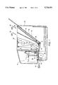
- FIG. 18 illustrates the exit mechanism 250 which is connected to a print mechanism chassis (not shown).
- a platen 273 is associated with the exit mechanism and forms a surface along which the printed media or document rides into the nip 204 between a roller 206 and star wheel 205 (also shown in FIG. 14). The platen also extends across the print mechanism chassis.
- An exit chassis 279 mounts a series of floating ribs 260 which are pivotably mounted on an integral shaft 277 (FIG. 19) extending across a like series of cut-outs 277a in a bottom edge 276 of the chassis 279.
- Each of the guide ribs 260 include a pair of guide surfaces 261 extending from a star wheel carrier 266 which includes an integral flat beam extending cantilevered transversely from chassis edge 276 upwardly to a distal end 267, which carrier is prevented against full rotation by a series of stops 268 integrally extending from a top opposite edge 278 (FIG. 19) of the chassis 279.
- a spring 271 extends from an integral boss 269 on the underside of beam 266 and an integral boss 270 extending from an interior wall of chassis 279 to provide a normal force on the star wheels 205 and against the printed media or document passing through the nip 204.
- the drive force (kickout) which moves the document or paper through the nip and into the output tray is equal to the normal force being provided by spring 271 times the coefficient of friction of the tires 206a (FIG. 18) on the roller 206.
- the guide ribs 260 also contain an apical end 262 having snap-in slots 263 into which opposite ends of a hub shaft 265 mounting a pair of freely rotatable star wheels 205 are snap-mounted.
- the distal legs forming the slot have sufficient flexibility to allow the ends of shaft to be held firmly, with a spaced pair of star wheels freely rotating about the shaft.
- a circular hub 264 (FIG. 22) spaces the star wheels.
- a printed media 200 typically a paper sheet
- the sheet passes along guide rib surfaces 261 after passing the series of star wheels so as to pass across the conical surfaces 218a of the conical rollers 218 to raise the wet paper edges as mentioned above, and to pass the sheet into an output tray (not shown).
- the guide ribs 260 are provided on all six star wheel assemblies as shown.
- the outer two star wheel ribs 260 i.e., one on each end of the chassis 279, namely assemblies 260a and 260b (FIG. 20) are functional since, when the front adjacing edge of the printed media or document goes up the ramps 273a integrally extending from the platen 273 and up on the conical rollers 218 (kicktires) to a radius on the print media or document outer edges, the rib surfaces 261 of the outer assemblies 260a and 260b are the only rib surfaces which contact the side edges of the printed media or document.
- the guide ribs When a thick document (or a thick printed media) passes over the platen 273 into the nip 204, the guide ribs (and carrier with attached series of star wheels) rotates or floats the apical end 262 upwardly, as shown by arrow 262a, moving integral beam 266 off the stop 268 on the chassis, and compressing spring 271.
- the guide ribs assembly 260 When the thick document (or a thick printed media) completes its passage through the nip 204 the guide ribs assembly 260 will rotate back adjacent to the stop 268 by expansion of the compressed spring 271 and guide surfaces 261 are returned to the normal printed media (paper) passage position.
- FIG. 19 illustrates the assembly of the guide ribs 260 into the cut-outs 277a with spring 271 extending from boss 270 to boss 269.
- the beams 266 include snap-in portions 285 which snap-onto the shafts 277 extending across the cut-outs.
- a kickstar holder 283 is pressed into chassis 279.
- a kickstar hub 284 mounts a star wheel 274 (FIG. 18) extending from the holder 283.
- the star wheel 274 presses or pinches the document or printed media (paper) against the conical wheels 218.
- the exit force is equal to the normal force provided by the weight of the brass hub times the coefficient of friction of the wheels against the paper which drives the back edge of the document or wet media to exit toward the output tray once it leaves the nip 204.
- a knob 280 extends from chassis 279 to provide an engagement member to snap-in a printer enclosure or cover (not shown).
- Chassis arms 272 attach to the print mechanism chassis (not shown).
- a curved section 290 of the arms 272 functions to provide a clearance for bushings which retain the print wheel roller 206 on the print mechanism chassis.
- FIG. 20 shows the assembly of the document deflector 210 (FIG. 17) to the chassis 279. Gears 286 and 287 are driven by a paper path motor (not shown) to rotate the conical wheels 218.
- Gears 286 and 287 are driven by a paper path motor (not shown) to rotate the conical wheels 218.
- Four centrally spaced guide ribs 260 are shown with outer guide ribs at each end of the chassis.
- An additional star wheel 274 (FIG. 18) is mounted on a longer shaft 277b by U-shaped arms extending from a shaft freely mounting a single star wheel (FIG. 18) downstream of the conical roller to ensure that the back trailing edge of the printed media or document is driven out into the output tray.
- FIG. 21 illustrates the mounting of conical rollers 218 and gears 286 and 287 into the chassis 279 by snap rings (not shown). Cut-outs 288 function to aid in the injection molding of the exit chassis 279.
- FIG. 22 shows a guide rib and star wheel carrier particularly the snap-in slots 285 for the mounting of the carrier onto shafts 277 and 277b.
- FIG. 23 shows the assembled star wheel hub and star wheel carrier guide rib used particularly at the ends of the edge 276 of chassis 279.
- FIG. 24 which is drawing sheet (FIG. 20) from the second mentioned related application illustrating the mechanism for rotating the document deflector 215 used to ensure non-jamming of a curled document entering the nip 204. Particularly it illustrates the deflector (flapper) up spring 239 and down spring 246, also shown in FIG. 20 hereof, as well as part of the deflector drive, including motor 241, housing 225 and drive gears 242 and 243.
Abstract
Description
Claims (15)
Priority Applications (1)
| Application Number | Priority Date | Filing Date | Title |
|---|---|---|---|
| US08/724,642 US5738454A (en) | 1993-10-29 | 1996-10-01 | Multiple-function printer with common output path mechanism with floating guide ribs to accommodate media and documents of different thickness |
Applications Claiming Priority (3)
| Application Number | Priority Date | Filing Date | Title |
|---|---|---|---|
| US14535593A | 1993-10-29 | 1993-10-29 | |
| US08/585,058 US5651623A (en) | 1993-10-29 | 1996-01-11 | Multiple-function printer with common feeder/output path mechanisms and method of operation |
| US08/724,642 US5738454A (en) | 1993-10-29 | 1996-10-01 | Multiple-function printer with common output path mechanism with floating guide ribs to accommodate media and documents of different thickness |
Related Parent Applications (1)
| Application Number | Title | Priority Date | Filing Date |
|---|---|---|---|
| US08/585,058 Continuation-In-Part US5651623A (en) | 1993-10-29 | 1996-01-11 | Multiple-function printer with common feeder/output path mechanisms and method of operation |
Publications (1)
| Publication Number | Publication Date |
|---|---|
| US5738454A true US5738454A (en) | 1998-04-14 |
Family
ID=26842885
Family Applications (1)
| Application Number | Title | Priority Date | Filing Date |
|---|---|---|---|
| US08/724,642 Expired - Lifetime US5738454A (en) | 1993-10-29 | 1996-10-01 | Multiple-function printer with common output path mechanism with floating guide ribs to accommodate media and documents of different thickness |
Country Status (1)
| Country | Link |
|---|---|
| US (1) | US5738454A (en) |
Cited By (39)
| Publication number | Priority date | Publication date | Assignee | Title |
|---|---|---|---|---|
| US6030134A (en) * | 1998-12-15 | 2000-02-29 | Jack Guttman, Inc. | Edible paper printer |
| US6189990B1 (en) * | 1996-03-08 | 2001-02-20 | Samsung Electronics Co., Ltd. | Apparatus for leaving space between paper and head of ink-jet printer |
| US20010013937A1 (en) * | 2000-01-19 | 2001-08-16 | Christoph Potakowskyj | Apparatus having guide means for guiding a record carrier to be scanned |
| WO2001064449A1 (en) * | 2000-03-02 | 2001-09-07 | Lexmark International, Inc. | Media feed unit for an ink jet printer |
| US20020080427A1 (en) * | 2000-12-21 | 2002-06-27 | Lori Clifton | Scanner including calibration target |
| US6450713B2 (en) * | 1999-09-10 | 2002-09-17 | Hewlett-Packard Company | Print media ejection system |
| US6457888B1 (en) * | 1999-08-20 | 2002-10-01 | Canon Kabushiki Kaisha | Sheet conveying apparatus |
| US6511227B1 (en) * | 2001-10-26 | 2003-01-28 | Hewlett-Packard Company | Removable bearing |
| US6619796B2 (en) | 2001-10-30 | 2003-09-16 | Hewlett-Packard Development Company, L.P. | Starwheel actuation timing for print media transport system and method |
| US6648677B1 (en) * | 2001-07-11 | 2003-11-18 | Peter A. Boyd | Wiring outlet with retractable extension cord mechanism |
| US20040020385A1 (en) * | 2002-07-30 | 2004-02-05 | Teo Cherng Linn | Wet printed media output system |
| US6695503B1 (en) | 2002-10-02 | 2004-02-24 | Lexmark International, Inc. | Print media feed system for an imaging apparatus |
| US20050116988A1 (en) * | 2003-12-01 | 2005-06-02 | Shun-Sheng Cheng | Method of a double starwheel unit in multiple rows with a multi-hole manner, an instrument and the like |
| US20050226667A1 (en) * | 1997-07-15 | 2005-10-13 | Silverbrook Research Pty Ltd. | Pagewidth printer and computer keyboard combination |
| US20050286942A1 (en) * | 2004-06-23 | 2005-12-29 | Canon Kabushiki Kaisha | Image processing apparatus |
| US20050285327A1 (en) * | 2004-06-23 | 2005-12-29 | Canon Kabushiki Kaisha | Image processing apparatus |
| US20050286943A1 (en) * | 2004-06-23 | 2005-12-29 | Canon Kabushiki Kaisha | Image processing apparatus |
| WO2006010478A1 (en) | 2004-07-28 | 2006-02-02 | Telecom Italia S.P.A. | Compact structure device for extracting sheets from two trays and respective printer |
| US7133169B2 (en) | 1996-11-05 | 2006-11-07 | Yoshiki Tsuchiyama | Apparatus equipped with removable scanner unit |
| US7379218B1 (en) | 1996-11-05 | 2008-05-27 | Fujitsu Limited | Apparatus equipped with removable scanner unit |
| US20090174133A1 (en) * | 2008-01-09 | 2009-07-09 | Samsung Electronics Co., Ltd. | Image forming apparatus |
| US20100309252A1 (en) * | 1997-07-15 | 2010-12-09 | Silverbrook Research Pty Ltd | Ejection nozzle arrangement |
| US20110096125A1 (en) * | 1997-07-15 | 2011-04-28 | Silverbrook Research Pty Ltd | Inkjet printhead with nozzle layer defining etchant holes |
| US20110109700A1 (en) * | 1997-07-15 | 2011-05-12 | Silverbrook Research Pty Ltd | Ink ejection mechanism with thermal actuator coil |
| US7950777B2 (en) | 1997-07-15 | 2011-05-31 | Silverbrook Research Pty Ltd | Ejection nozzle assembly |
| US20110134193A1 (en) * | 1997-07-15 | 2011-06-09 | Silverbrook Research Pty Ltd | Nozzle arrangement with an actuator having iris vanes |
| US20110157280A1 (en) * | 1997-07-15 | 2011-06-30 | Silverbrook Research Pty Ltd | Printhead nozzle arrangements with magnetic paddle actuators |
| US20110175970A1 (en) * | 1997-07-15 | 2011-07-21 | Silverbrook Research Pty Ltd | Inkjet printhead integrated circuit incorporating fulcrum assisted ink ejection actuator |
| US20110211025A1 (en) * | 1997-07-15 | 2011-09-01 | Silverbrook Research Pty Ltd | Printhead nozzle having heater of higher resistance than contacts |
| US20110211020A1 (en) * | 1997-07-15 | 2011-09-01 | Silverbrook Research Pty Ltd | Printhead micro-electromechanical nozzle arrangement with motion-transmitting structure |
| US20110228008A1 (en) * | 1997-07-15 | 2011-09-22 | Silverbrook Research Pty Ltd | Printhead having relatively sized fluid ducts and nozzles |
| US8029102B2 (en) | 1997-07-15 | 2011-10-04 | Silverbrook Research Pty Ltd | Printhead having relatively dimensioned ejection ports and arms |
| US8061812B2 (en) | 1997-07-15 | 2011-11-22 | Silverbrook Research Pty Ltd | Ejection nozzle arrangement having dynamic and static structures |
| US8861051B1 (en) * | 2013-08-14 | 2014-10-14 | Foxlink Image Technology Co., Ltd. | Roller assembly |
| WO2015016810A1 (en) * | 2013-07-29 | 2015-02-05 | Hewlett-Packard Development Company, L.P. | Media output guide assembly |
| US9742942B2 (en) | 2011-05-04 | 2017-08-22 | Hewlett-Packard Development Company, L.P. | Imaging device assembly |
| TWI613901B (en) * | 2015-10-16 | 2018-02-01 | 精工愛普生股份有限公司 | Medium discharge device and image reading apparatus |
| US10647132B2 (en) | 2016-06-23 | 2020-05-12 | Hewlett-Packard Development Company, L. P. | Partially dried inkjet media output management |
| US11097912B2 (en) | 2019-06-20 | 2021-08-24 | Xerox Corporation | Tethered trailing edge media guide |
Citations (13)
| Publication number | Priority date | Publication date | Assignee | Title |
|---|---|---|---|---|
| US4511904A (en) * | 1982-10-18 | 1985-04-16 | Tokyo Shibaura Denki Kabushiki Kaisha | Recording apparatus |
| US4657420A (en) * | 1983-09-20 | 1987-04-14 | Canon Kabushiki Kaisha | Paper feed mechanism |
| US4688957A (en) * | 1984-11-19 | 1987-08-25 | Ingf. C. Olivetti & C., S.p.A. | Feeder for office machines for individual sheet or continuous forms |
| US4729683A (en) * | 1986-01-24 | 1988-03-08 | Ziyad Incorporated | Paper sheet feeding apparatus |
| US4802778A (en) * | 1985-04-09 | 1989-02-07 | Brother Kogyo Kabushiki Kaisha | Carriage drive control device in a printing device |
| JPS6488376A (en) * | 1987-09-30 | 1989-04-03 | Hewlett Packard Yokogawa | Sweep measuring instrument |
| US4997179A (en) * | 1988-11-08 | 1991-03-05 | Oki Electric Industry Co., Ltd. | Automatic sheet feeding device |
| DE4135308A1 (en) * | 1990-10-25 | 1992-04-30 | Alps Electric Co Ltd | Printer with paper stack loader - with facility for manual input or sheet feed with output to one point |
| US5124800A (en) * | 1986-10-28 | 1992-06-23 | Canon Kabushiki Kaisha | Apparatus for reading and recording image |
| US5141344A (en) * | 1990-02-07 | 1992-08-25 | Seiko Epson Corporation | Sheet feeding mechanism for printing apparatus |
| US5162916A (en) * | 1990-07-02 | 1992-11-10 | Xerox Corporation | Compact read/write scanner |
| US5215394A (en) * | 1991-04-12 | 1993-06-01 | Goldstar Co., Ltd. | Apparatus for discharging printing paper in a color video printer |
| US5558451A (en) * | 1989-12-29 | 1996-09-24 | Canon Kabushiki Kaisha | Shiftable guide member with rollers in a sheet feeding apparatus |
-
1996
- 1996-10-01 US US08/724,642 patent/US5738454A/en not_active Expired - Lifetime
Patent Citations (13)
| Publication number | Priority date | Publication date | Assignee | Title |
|---|---|---|---|---|
| US4511904A (en) * | 1982-10-18 | 1985-04-16 | Tokyo Shibaura Denki Kabushiki Kaisha | Recording apparatus |
| US4657420A (en) * | 1983-09-20 | 1987-04-14 | Canon Kabushiki Kaisha | Paper feed mechanism |
| US4688957A (en) * | 1984-11-19 | 1987-08-25 | Ingf. C. Olivetti & C., S.p.A. | Feeder for office machines for individual sheet or continuous forms |
| US4802778A (en) * | 1985-04-09 | 1989-02-07 | Brother Kogyo Kabushiki Kaisha | Carriage drive control device in a printing device |
| US4729683A (en) * | 1986-01-24 | 1988-03-08 | Ziyad Incorporated | Paper sheet feeding apparatus |
| US5124800A (en) * | 1986-10-28 | 1992-06-23 | Canon Kabushiki Kaisha | Apparatus for reading and recording image |
| JPS6488376A (en) * | 1987-09-30 | 1989-04-03 | Hewlett Packard Yokogawa | Sweep measuring instrument |
| US4997179A (en) * | 1988-11-08 | 1991-03-05 | Oki Electric Industry Co., Ltd. | Automatic sheet feeding device |
| US5558451A (en) * | 1989-12-29 | 1996-09-24 | Canon Kabushiki Kaisha | Shiftable guide member with rollers in a sheet feeding apparatus |
| US5141344A (en) * | 1990-02-07 | 1992-08-25 | Seiko Epson Corporation | Sheet feeding mechanism for printing apparatus |
| US5162916A (en) * | 1990-07-02 | 1992-11-10 | Xerox Corporation | Compact read/write scanner |
| DE4135308A1 (en) * | 1990-10-25 | 1992-04-30 | Alps Electric Co Ltd | Printer with paper stack loader - with facility for manual input or sheet feed with output to one point |
| US5215394A (en) * | 1991-04-12 | 1993-06-01 | Goldstar Co., Ltd. | Apparatus for discharging printing paper in a color video printer |
Cited By (64)
| Publication number | Priority date | Publication date | Assignee | Title |
|---|---|---|---|---|
| US6189990B1 (en) * | 1996-03-08 | 2001-02-20 | Samsung Electronics Co., Ltd. | Apparatus for leaving space between paper and head of ink-jet printer |
| US7133169B2 (en) | 1996-11-05 | 2006-11-07 | Yoshiki Tsuchiyama | Apparatus equipped with removable scanner unit |
| US7379218B1 (en) | 1996-11-05 | 2008-05-27 | Fujitsu Limited | Apparatus equipped with removable scanner unit |
| US8075104B2 (en) | 1997-07-15 | 2011-12-13 | Sliverbrook Research Pty Ltd | Printhead nozzle having heater of higher resistance than contacts |
| US20050226667A1 (en) * | 1997-07-15 | 2005-10-13 | Silverbrook Research Pty Ltd. | Pagewidth printer and computer keyboard combination |
| US7950777B2 (en) | 1997-07-15 | 2011-05-31 | Silverbrook Research Pty Ltd | Ejection nozzle assembly |
| US8061812B2 (en) | 1997-07-15 | 2011-11-22 | Silverbrook Research Pty Ltd | Ejection nozzle arrangement having dynamic and static structures |
| US20110175970A1 (en) * | 1997-07-15 | 2011-07-21 | Silverbrook Research Pty Ltd | Inkjet printhead integrated circuit incorporating fulcrum assisted ink ejection actuator |
| US20110109700A1 (en) * | 1997-07-15 | 2011-05-12 | Silverbrook Research Pty Ltd | Ink ejection mechanism with thermal actuator coil |
| US20110096125A1 (en) * | 1997-07-15 | 2011-04-28 | Silverbrook Research Pty Ltd | Inkjet printhead with nozzle layer defining etchant holes |
| US20110211025A1 (en) * | 1997-07-15 | 2011-09-01 | Silverbrook Research Pty Ltd | Printhead nozzle having heater of higher resistance than contacts |
| US20100309252A1 (en) * | 1997-07-15 | 2010-12-09 | Silverbrook Research Pty Ltd | Ejection nozzle arrangement |
| US20110211020A1 (en) * | 1997-07-15 | 2011-09-01 | Silverbrook Research Pty Ltd | Printhead micro-electromechanical nozzle arrangement with motion-transmitting structure |
| US8020970B2 (en) | 1997-07-15 | 2011-09-20 | Silverbrook Research Pty Ltd | Printhead nozzle arrangements with magnetic paddle actuators |
| US20110228008A1 (en) * | 1997-07-15 | 2011-09-22 | Silverbrook Research Pty Ltd | Printhead having relatively sized fluid ducts and nozzles |
| US7217048B2 (en) * | 1997-07-15 | 2007-05-15 | Silverbrook Research Pty Ltd | Pagewidth printer and computer keyboard combination |
| US20110134193A1 (en) * | 1997-07-15 | 2011-06-09 | Silverbrook Research Pty Ltd | Nozzle arrangement with an actuator having iris vanes |
| US8123336B2 (en) | 1997-07-15 | 2012-02-28 | Silverbrook Research Pty Ltd | Printhead micro-electromechanical nozzle arrangement with motion-transmitting structure |
| US8113629B2 (en) | 1997-07-15 | 2012-02-14 | Silverbrook Research Pty Ltd. | Inkjet printhead integrated circuit incorporating fulcrum assisted ink ejection actuator |
| US8083326B2 (en) | 1997-07-15 | 2011-12-27 | Silverbrook Research Pty Ltd | Nozzle arrangement with an actuator having iris vanes |
| US20110211023A1 (en) * | 1997-07-15 | 2011-09-01 | Silverbrook Research Pty Ltd | Printhead ejection nozzle |
| US8029102B2 (en) | 1997-07-15 | 2011-10-04 | Silverbrook Research Pty Ltd | Printhead having relatively dimensioned ejection ports and arms |
| US8025366B2 (en) | 1997-07-15 | 2011-09-27 | Silverbrook Research Pty Ltd | Inkjet printhead with nozzle layer defining etchant holes |
| US20110157280A1 (en) * | 1997-07-15 | 2011-06-30 | Silverbrook Research Pty Ltd | Printhead nozzle arrangements with magnetic paddle actuators |
| US8029101B2 (en) | 1997-07-15 | 2011-10-04 | Silverbrook Research Pty Ltd | Ink ejection mechanism with thermal actuator coil |
| US6030134A (en) * | 1998-12-15 | 2000-02-29 | Jack Guttman, Inc. | Edible paper printer |
| US6457888B1 (en) * | 1999-08-20 | 2002-10-01 | Canon Kabushiki Kaisha | Sheet conveying apparatus |
| US6450713B2 (en) * | 1999-09-10 | 2002-09-17 | Hewlett-Packard Company | Print media ejection system |
| US6987574B2 (en) * | 2000-01-19 | 2006-01-17 | Sagem Sa | Apparatus having guide means for guiding a record carrier to be scanned |
| US20010013937A1 (en) * | 2000-01-19 | 2001-08-16 | Christoph Potakowskyj | Apparatus having guide means for guiding a record carrier to be scanned |
| WO2001064449A1 (en) * | 2000-03-02 | 2001-09-07 | Lexmark International, Inc. | Media feed unit for an ink jet printer |
| US6371611B1 (en) * | 2000-03-02 | 2002-04-16 | Lexmark International, Inc. | Media feed unit for an ink jet printer |
| US7149002B2 (en) | 2000-12-21 | 2006-12-12 | Hewlett-Packard Development Company, L.P. | Scanner including calibration target |
| US20020080427A1 (en) * | 2000-12-21 | 2002-06-27 | Lori Clifton | Scanner including calibration target |
| US6648677B1 (en) * | 2001-07-11 | 2003-11-18 | Peter A. Boyd | Wiring outlet with retractable extension cord mechanism |
| US6511227B1 (en) * | 2001-10-26 | 2003-01-28 | Hewlett-Packard Company | Removable bearing |
| US20040017465A1 (en) * | 2001-10-30 | 2004-01-29 | Rasmussen Steve O. | Starwheel actuation timing for print media transport system and method |
| US6619796B2 (en) | 2001-10-30 | 2003-09-16 | Hewlett-Packard Development Company, L.P. | Starwheel actuation timing for print media transport system and method |
| US7018034B2 (en) | 2001-10-30 | 2006-03-28 | Hewlett-Packard Development Company, L.P. | Starwheel actuation timing for print media transport system and method |
| US20040020385A1 (en) * | 2002-07-30 | 2004-02-05 | Teo Cherng Linn | Wet printed media output system |
| US6722802B2 (en) * | 2002-07-30 | 2004-04-20 | Hewlett-Packard Development Company, L.P. | Wet printed media output system |
| US6695503B1 (en) | 2002-10-02 | 2004-02-24 | Lexmark International, Inc. | Print media feed system for an imaging apparatus |
| US20050116988A1 (en) * | 2003-12-01 | 2005-06-02 | Shun-Sheng Cheng | Method of a double starwheel unit in multiple rows with a multi-hole manner, an instrument and the like |
| US20050286943A1 (en) * | 2004-06-23 | 2005-12-29 | Canon Kabushiki Kaisha | Image processing apparatus |
| US7556255B2 (en) | 2004-06-23 | 2009-07-07 | Canon Kabushiki Kaisha | Image processing apparatus |
| US8081919B2 (en) | 2004-06-23 | 2011-12-20 | Canon Kabushiki Kaisha | Image processing apparatus |
| US20050286942A1 (en) * | 2004-06-23 | 2005-12-29 | Canon Kabushiki Kaisha | Image processing apparatus |
| US20050285327A1 (en) * | 2004-06-23 | 2005-12-29 | Canon Kabushiki Kaisha | Image processing apparatus |
| US7513493B2 (en) | 2004-06-23 | 2009-04-07 | Canon Kabushiki Kaisha | Image processing apparatus |
| EP1609605A3 (en) * | 2004-06-23 | 2009-03-11 | Canon Kabushiki Kaisha | Image processing apparatus |
| WO2006010478A1 (en) | 2004-07-28 | 2006-02-02 | Telecom Italia S.P.A. | Compact structure device for extracting sheets from two trays and respective printer |
| CN1989055B (en) * | 2004-07-28 | 2010-06-16 | 意大利电信股份公司 | Device used for extracting and feeding paper sheets, facsimile machine and method for feeding paper sheets selectively |
| US7815183B2 (en) | 2004-07-28 | 2010-10-19 | Telecom Italia S.P.A. | Compact structure device for extracting sheets from two trays and respective printer |
| US20080315501A1 (en) * | 2004-07-28 | 2008-12-25 | Telecom Italia S.P.A. | Compact Structure Device for Extracting Sheets from Two Trays and Respective Printer |
| US20090174133A1 (en) * | 2008-01-09 | 2009-07-09 | Samsung Electronics Co., Ltd. | Image forming apparatus |
| US7909318B2 (en) * | 2008-01-09 | 2011-03-22 | Samsung Electronics Co., Ltd. | Image forming apparatus |
| US9742942B2 (en) | 2011-05-04 | 2017-08-22 | Hewlett-Packard Development Company, L.P. | Imaging device assembly |
| WO2015016810A1 (en) * | 2013-07-29 | 2015-02-05 | Hewlett-Packard Development Company, L.P. | Media output guide assembly |
| US9656484B2 (en) | 2013-07-29 | 2017-05-23 | Hewlett-Packard Development Company, L.P. | Media output guide assembly |
| US8861051B1 (en) * | 2013-08-14 | 2014-10-14 | Foxlink Image Technology Co., Ltd. | Roller assembly |
| TWI613901B (en) * | 2015-10-16 | 2018-02-01 | 精工愛普生股份有限公司 | Medium discharge device and image reading apparatus |
| TWI655856B (en) * | 2015-10-16 | 2019-04-01 | 日商精工愛普生股份有限公司 | Media transfer device and image reading device |
| US10647132B2 (en) | 2016-06-23 | 2020-05-12 | Hewlett-Packard Development Company, L. P. | Partially dried inkjet media output management |
| US11097912B2 (en) | 2019-06-20 | 2021-08-24 | Xerox Corporation | Tethered trailing edge media guide |
Similar Documents
| Publication | Publication Date | Title |
|---|---|---|
| US5738454A (en) | Multiple-function printer with common output path mechanism with floating guide ribs to accommodate media and documents of different thickness | |
| US5651623A (en) | Multiple-function printer with common feeder/output path mechanisms and method of operation | |
| US5727890A (en) | Multiple-function printer with common mounting chassis feeder/output path mechanisms | |
| EP0650842B1 (en) | Single motor actuation for automatic stack feeder system in a hardcopy device | |
| US6542263B2 (en) | Automatic document feeder with improved sheet handling capabilities and method of feeding and scanning over-sized media sheets | |
| US8503923B2 (en) | Image recording apparatus | |
| JPH07175279A (en) | Manuscript processor | |
| US5800083A (en) | Multiple-function printer document deflector actuation coupled to service station actuation | |
| EP0650843B1 (en) | Multiple-function printer with common feeder/output path mechanisms | |
| US20070102873A1 (en) | Apparatus for varying pressure roll nip force | |
| US7618035B2 (en) | Image recording apparatus | |
| US20060280534A1 (en) | Apparatus for and method of creating a duplex scan using a single pass ADF | |
| US20070003343A1 (en) | Duplexing ADF using a paperpath shorter than the length of paper to be duplexed | |
| EP0915044B1 (en) | Resistance plate in a sheet feed device | |
| CN102126628A (en) | Sheet feeder and image forming apparatus incorporating same | |
| US6361037B1 (en) | Sheet feeding apparatus, image reading apparatus and image forming apparatus | |
| US6443446B1 (en) | Media transport mechanism for information transfer devices | |
| JPH08169595A (en) | Sheet material feeder and recorder | |
| JPH08143208A (en) | Printing device | |
| US7905480B2 (en) | Job separator and image recording apparatus having the same | |
| JPH06191650A (en) | Automatic paper feeding device and recording device | |
| JP2005057340A (en) | Image reading and recording apparatus and facsimile machine | |
| KR100208800B1 (en) | Inkjet facsimile | |
| JP3363827B2 (en) | Automatic feeding device and recording device using the same | |
| JPH06263291A (en) | Automatic sheet feeder and recorder |
Legal Events
| Date | Code | Title | Description |
|---|---|---|---|
| AS | Assignment |
Owner name: HEWLETT-PACKARD COMPANY, CALIFORNIA Free format text: ASSIGNMENT OF ASSIGNORS INTEREST;ASSIGNORS:ZEPEDA, CAROLINE M.;STODDER, SAMUEL A.;REEL/FRAME:008324/0435 Effective date: 19960927 |
|
| STCF | Information on status: patent grant |
Free format text: PATENTED CASE |
|
| FEPP | Fee payment procedure |
Free format text: PAYOR NUMBER ASSIGNED (ORIGINAL EVENT CODE: ASPN); ENTITY STATUS OF PATENT OWNER: LARGE ENTITY |
|
| AS | Assignment |
Owner name: HEWLETT-PACKARD COMPANY, COLORADO Free format text: MERGER;ASSIGNOR:HEWLETT-PACKARD COMPANY;REEL/FRAME:011523/0469 Effective date: 19980520 |
|
| FPAY | Fee payment |
Year of fee payment: 4 |
|
| FPAY | Fee payment |
Year of fee payment: 8 |
|
| FPAY | Fee payment |
Year of fee payment: 12 |
|
| AS | Assignment |
Owner name: HEWLETT-PACKARD DEVELOPMENT COMPANY, L.P., TEXAS Free format text: ASSIGNMENT OF ASSIGNORS INTEREST;ASSIGNOR:HEWLETT-PACKARD COMPANY;REEL/FRAME:026945/0699 Effective date: 20030131 |