US5740047A - GNSS based, seamless, multi-dimensional control and management system for vehicles operating in a multi-dimensional environment - Google Patents

GNSS based, seamless, multi-dimensional control and management system for vehicles operating in a multi-dimensional environment Download PDF

Info

Publication number
US5740047A
US5740047A US08/651,837 US65183796A US5740047A US 5740047 A US5740047 A US 5740047A US 65183796 A US65183796 A US 65183796A US 5740047 A US5740047 A US 5740047A
Authority
US
United States
Prior art keywords
vehicle
database
zone
velocity
waypoints
Prior art date
Legal status (The legal status is an assumption and is not a legal conclusion. Google has not performed a legal analysis and makes no representation as to the accuracy of the status listed.)
Expired - Lifetime
Application number
US08/651,837
Inventor
Harold Robert Pilley
Lois V. Pilley
Current Assignee (The listed assignees may be inaccurate. Google has not performed a legal analysis and makes no representation or warranty as to the accuracy of the list.)
Honeywell Intellectual Properties Inc
Original Assignee
Harold R. Pilley
Priority date (The priority date is an assumption and is not a legal conclusion. Google has not performed a legal analysis and makes no representation as to the accuracy of the date listed.)
Filing date
Publication date
Family has litigation
First worldwide family litigation filed litigation Critical https://patents.darts-ip.com/?family=27081648&utm_source=google_patent&utm_medium=platform_link&utm_campaign=public_patent_search&patent=US5740047(A) "Global patent litigation dataset” by Darts-ip is licensed under a Creative Commons Attribution 4.0 International License.
Priority claimed from US07/593,214 external-priority patent/US5200902A/en
Application filed by Harold R. Pilley filed Critical Harold R. Pilley
Priority to US08/651,837 priority Critical patent/US5740047A/en
Assigned to PILLEY,HAROLD ROBERT reassignment PILLEY,HAROLD ROBERT ASSIGNMENT OF ASSIGNORS INTEREST (SEE DOCUMENT FOR DETAILS). Assignors: PILLEY, LOIS V.
Publication of US5740047A publication Critical patent/US5740047A/en
Application granted granted Critical
Priority to US09/304,037 priority patent/US6182005B1/en
Priority to US09/871,328 priority patent/US20030083804A1/en
Priority to US10/733,968 priority patent/US20040225432A1/en
Anticipated expiration legal-status Critical
Assigned to HONEYWELL INTELLECTUAL PROPERTIES, INC. (NOW BRH LLC) reassignment HONEYWELL INTELLECTUAL PROPERTIES, INC. (NOW BRH LLC) ASSIGNMENT OF ASSIGNORS INTEREST (SEE DOCUMENT FOR DETAILS). Assignors: PILLEY, HAROLD ROBERT
Expired - Lifetime legal-status Critical Current

Links

Images

Classifications

    • GPHYSICS
    • G08SIGNALLING
    • G08GTRAFFIC CONTROL SYSTEMS
    • G08G5/00Traffic control systems for aircraft, e.g. air-traffic control [ATC]
    • G08G5/0017Arrangements for implementing traffic-related aircraft activities, e.g. arrangements for generating, displaying, acquiring or managing traffic information
    • G08G5/0026Arrangements for implementing traffic-related aircraft activities, e.g. arrangements for generating, displaying, acquiring or managing traffic information located on the ground
    • GPHYSICS
    • G01MEASURING; TESTING
    • G01CMEASURING DISTANCES, LEVELS OR BEARINGS; SURVEYING; NAVIGATION; GYROSCOPIC INSTRUMENTS; PHOTOGRAMMETRY OR VIDEOGRAMMETRY
    • G01C23/00Combined instruments indicating more than one navigational value, e.g. for aircraft; Combined measuring devices for measuring two or more variables of movement, e.g. distance, speed or acceleration
    • GPHYSICS
    • G01MEASURING; TESTING
    • G01SRADIO DIRECTION-FINDING; RADIO NAVIGATION; DETERMINING DISTANCE OR VELOCITY BY USE OF RADIO WAVES; LOCATING OR PRESENCE-DETECTING BY USE OF THE REFLECTION OR RERADIATION OF RADIO WAVES; ANALOGOUS ARRANGEMENTS USING OTHER WAVES
    • G01S1/00Beacons or beacon systems transmitting signals having a characteristic or characteristics capable of being detected by non-directional receivers and defining directions, positions, or position lines fixed relatively to the beacon transmitters; Receivers co-operating therewith
    • G01S1/02Beacons or beacon systems transmitting signals having a characteristic or characteristics capable of being detected by non-directional receivers and defining directions, positions, or position lines fixed relatively to the beacon transmitters; Receivers co-operating therewith using radio waves
    • G01S1/04Details
    • G01S1/047Displays or indicators
    • GPHYSICS
    • G01MEASURING; TESTING
    • G01SRADIO DIRECTION-FINDING; RADIO NAVIGATION; DETERMINING DISTANCE OR VELOCITY BY USE OF RADIO WAVES; LOCATING OR PRESENCE-DETECTING BY USE OF THE REFLECTION OR RERADIATION OF RADIO WAVES; ANALOGOUS ARRANGEMENTS USING OTHER WAVES
    • G01S19/00Satellite radio beacon positioning systems; Determining position, velocity or attitude using signals transmitted by such systems
    • G01S19/01Satellite radio beacon positioning systems transmitting time-stamped messages, e.g. GPS [Global Positioning System], GLONASS [Global Orbiting Navigation Satellite System] or GALILEO
    • G01S19/03Cooperating elements; Interaction or communication between different cooperating elements or between cooperating elements and receivers
    • G01S19/07Cooperating elements; Interaction or communication between different cooperating elements or between cooperating elements and receivers providing data for correcting measured positioning data, e.g. DGPS [differential GPS] or ionosphere corrections
    • GPHYSICS
    • G01MEASURING; TESTING
    • G01SRADIO DIRECTION-FINDING; RADIO NAVIGATION; DETERMINING DISTANCE OR VELOCITY BY USE OF RADIO WAVES; LOCATING OR PRESENCE-DETECTING BY USE OF THE REFLECTION OR RERADIATION OF RADIO WAVES; ANALOGOUS ARRANGEMENTS USING OTHER WAVES
    • G01S19/00Satellite radio beacon positioning systems; Determining position, velocity or attitude using signals transmitted by such systems
    • G01S19/01Satellite radio beacon positioning systems transmitting time-stamped messages, e.g. GPS [Global Positioning System], GLONASS [Global Orbiting Navigation Satellite System] or GALILEO
    • G01S19/13Receivers
    • G01S19/14Receivers specially adapted for specific applications
    • G01S19/15Aircraft landing systems
    • GPHYSICS
    • G01MEASURING; TESTING
    • G01SRADIO DIRECTION-FINDING; RADIO NAVIGATION; DETERMINING DISTANCE OR VELOCITY BY USE OF RADIO WAVES; LOCATING OR PRESENCE-DETECTING BY USE OF THE REFLECTION OR RERADIATION OF RADIO WAVES; ANALOGOUS ARRANGEMENTS USING OTHER WAVES
    • G01S5/00Position-fixing by co-ordinating two or more direction or position line determinations; Position-fixing by co-ordinating two or more distance determinations
    • G01S5/0009Transmission of position information to remote stations
    • GPHYSICS
    • G08SIGNALLING
    • G08GTRAFFIC CONTROL SYSTEMS
    • G08G5/00Traffic control systems for aircraft, e.g. air-traffic control [ATC]
    • G08G5/0004Transmission of traffic-related information to or from an aircraft
    • G08G5/0013Transmission of traffic-related information to or from an aircraft with a ground station
    • GPHYSICS
    • G08SIGNALLING
    • G08GTRAFFIC CONTROL SYSTEMS
    • G08G5/00Traffic control systems for aircraft, e.g. air-traffic control [ATC]
    • G08G5/0073Surveillance aids
    • G08G5/0082Surveillance aids for monitoring traffic from a ground station
    • GPHYSICS
    • G01MEASURING; TESTING
    • G01SRADIO DIRECTION-FINDING; RADIO NAVIGATION; DETERMINING DISTANCE OR VELOCITY BY USE OF RADIO WAVES; LOCATING OR PRESENCE-DETECTING BY USE OF THE REFLECTION OR RERADIATION OF RADIO WAVES; ANALOGOUS ARRANGEMENTS USING OTHER WAVES
    • G01S19/00Satellite radio beacon positioning systems; Determining position, velocity or attitude using signals transmitted by such systems
    • G01S19/38Determining a navigation solution using signals transmitted by a satellite radio beacon positioning system
    • G01S19/39Determining a navigation solution using signals transmitted by a satellite radio beacon positioning system the satellite radio beacon positioning system transmitting time-stamped messages, e.g. GPS [Global Positioning System], GLONASS [Global Orbiting Navigation Satellite System] or GALILEO
    • G01S19/53Determining attitude

Definitions

  • the inventor has taken an active stand to promote the technology in a public manner and, as such, may have informed others to key elements of this application.
  • the inventor has promoted this technology.
  • DSDC's airports philosophy has been described in general terms to the aviation industry since it was felt industry and government awareness was necessary.
  • the intent of this application is to identify and protect key elements of the system.
  • This invention most generally is a system and a method for the control of surface and airborne traffic within a defined space envelope.
  • GNSS-based, or GPS based data is used to define and create a 3-dimensional map, define locations, to compute trajectories, speeds, velocities, static and dynamic regions and spaces or volumes (zones) including zones identified as forbidden zones.
  • Databases are also created, which are compatible with the GNSS data. Some of these databases may contain, vehicle information such as type and shape, static zones including zones specific to vehicle type which are forbidden to the type of vehicle, notice to airmen (notams) characterized by the information or GNSS data.
  • the GNSS data in combination with the databases is used, for example, by air traffic control, to control and manage the flow of traffic approaching and departing the airport and the control of the flow of surface vehicles and taxiing aircraft.
  • All or a selected group of vehicles may have GNSS receivers. Additionally, all or a selected group may have bi-directional digital data and voice communications between vehicles and also with air traffic control. All of the data is made compatible for display on a screen or selected screens for use and observation including screens located on selected vehicles and aircraft.
  • Vehicle/aircraft data may be compatibly superimposed with the 3-dimensional map data and the combination of data displayed or displayable may be manipulated to provide selected viewing. The selected viewing may be in the form of choice of the line of observation, the viewing may be by layers based upon the data and the objective for the use of the data.
  • a 4-D process logic flow which provides a "seamless" airport environment on the ground and in the air anywhere in the world with a common 3-D coordinate reference and time
  • a 4-D process logic flow which provides precise vehicle waypoint navigation in the air and on the ground. This process allows for monitoring of on or off course conditions for vehicles and aircraft operating within the airport space envelope on board the vehicle.
  • a 4-D process logic flow which provides precise ATC waypoint navigation mirroring of actual vehicles in the air and on the ground at ATC. This process allows for monitoring of on or off course conditions for vehicles and aircraft operating within the airport space envelope at the ATC computer
  • a collision detection management method which utilizes the application of false alarm reducing methods
  • An ATC process logic flow which detects 3-D runway incursions. The process logic then generates message alerts and controls airport lights
  • a vehicle process logic flow which detects 3-D runway incursions. The process logic then generates message alerts and sounds tones within the vehicle or aircraft
  • a vehicle zone management method which utilizes the application of false alarm reducing methods
  • a 4-D ATC process logic flow which manages ground and air "Clearances" with precise waypoint navigation aboard the vehicle and at the ATC computer.
  • a 4-D ATC process logic flow which manages ground and air "Clearances" incorporating an integrated system of controlling airport lights.
  • a 4-D vehicle process logic flow which manages ground and air "Clearances" with an integrated system of waypoint navigation.
  • Zones database management methods are used aboard the vehicle and at ATC
  • a operational management method where the ATC computer provides navigational instructions to vehicles and aircraft. The instructions result in a travel path with clear paths defined being displayed in an airport map
  • a operational management method where the ATC computer provides navigational instructions to vehicles and aircraft The instructions result in waypoints being entered into a 4-D navigation computer
  • FIG. 1 depicts the high-level Airport Control and Management processing elements and flow.
  • FIG. 2 represents an example of a cylindrical static zone in a 3-D ALP. This zone could be graphically displayed in a layer of the ALP.
  • FIG. 3 represents an example of a static zone around a construction area of the airport and is used in zone incursion processing in the vehicles and at the ATC Processor.
  • FIG. 4 represents an example of a dynamic zone which travels with a moving vehicle, in this case the zone represents the minimum safe clearance spacing which would be used in zone based collision detection processing in the vehicles and at the ATC processor.
  • FIG. 5 represents an example of a route zone which is defined by navigational waypoints and is used for on ⁇ off course processing and is used in the vehicles and at the ATC Processor.
  • FIG. 6 represents an example of a 3-D ATC zone, used to segregate tracked vehicles to particular ATC stations.
  • FIG. 7 illustrates the construction of a 3-D runway zone.
  • FIG. 8 shows a map display with surface waypoints and travel path
  • FIG. 9 shows a map display with departure waypoints and travel path.
  • FIG. 10 illustrates the 4-D collision detection mechanism employed in the Airport Control and Management System.
  • FIG. 11 waypoint processing diagram showing the earth and ECEF coordinate system, expanded view of airport waypoints, further expanded view of previous and next waypoint geometry with present position, the cross hair display presentation used in the developed GPS navigator.
  • FIG. 12 Latitude, Longitude plot of a missed approach followed by a touch and go with waypoints indicated about every 20 seconds.
  • FIG. 13 Altitude vs time for missed approach followed by touch and go, waypoints are indicated about every 20 seconds.
  • FIG. 14 graphs ECEF X and Y presentation of missed approach followed by a touch and go with waypoints indicated about every 20 seconds.
  • FIG. 15 graphs ECEF Z versus time of missed approach followed by touch and go, with waypoints about every 20 seconds.
  • FIG. 16 shows a block diagram of on ⁇ off course processing.
  • the primary Airport Control and Management (AC&M) functions of the invention utilize a cartesian ECEF X, Y, Z coordinate frame compatible with GNSS.
  • FIG. 1 provides additional detail for the operational elements of the AC&M processing.
  • the GNSS signals broadcast by the vehicles 8 are processed by the Real Time Communication Handler 3 and sent to AC&M Operational Control 1.
  • the Operational Control 1 uses the GNSS data to perform the following processing functions 5: position projections, coordinate conversions, zone detection, collision prediction, runway incursion detection, layer filter, alarm control, and lighting control. If waypoints have been issued to the vehicle 8, mirrored waypoint navigation is also performed by the AC&M processing.
  • the Operational Control 1 interfaces directly to the Graphical Control 2.
  • Graphics messages, including GNSS data and coded information pertaining to zone incursions, possible collision conditions, or off course conditions detected by the AC&M Processing are passed to the Graphical Control 2.
  • the Graphical Control 2 interprets this data and updates the display presentation accordingly.
  • the Operational Control 1 function also receives inputs from the Controller/Operator Interface 6.
  • the Controller/Operator Interface uses the data received by Controller/Operator Inputs 7 to compose ATC commands which are sent to the Operational Control 1 function for processing. Commands affecting the presentation on the computer display screen are sent by the Operational Control 1 function to the Graphical Control 2.
  • ATC commands composed by the Controller/Operator Interface 6 processing that do not require further AC&M processing are forwarded directly to the Graphical Control 2 to update the display screen.
  • Both the Operational Control 1 function and Graphical Control 2 processing have access to the Monumentation, Aircraft/Vehicle, Static Zones, Waypoints, Airport Map, ATIS Interface and Airport Status and other low level data bases 9 to process and manipulate the presentation of map and vehicle data on a computer display screen.
  • each vehicle 8 supports the capability to transmit a minimum of an identifier, the GNSS referenced position of one or more antennas, velocity, optional acceleration and time reports. Since this data is broadcast, it is accessible to the airport control tower, other aircraft and vehicles in the local area, and various airline monitoring or emergency command centers which may perform similar processing functions.
  • ATC commands processed by the Controller/Operator Interface 6 and Operational Control 1 function are passed to the Real Time Communication Handler 3 for transmission to the aircraft/vehicle(s) 8.
  • the vehicle(s) 8 Upon receipt of ATC messages, the vehicle(s) 8 return an acknowledgment message which is received by the Real Time communication Handler 3 and passed to the Operational Control 1 function.
  • Differential GNSS corrections are generated by the Differential GPS Processor 4 and passed to the Real Time Communication Handler 3 for broadcast to the vehicles.
  • the Real Time Communication Handler 8 performs the following functions at a minimum:
  • ALP airport layout plan
  • NAD 83 Lat, Lon, MSL and State Plane
  • WGS 84 X,Y,Z
  • ALP airport layout plan
  • the Airport Control and Management System AC&M
  • ADS Automatic dependent Surveillance
  • the processing methods described herein, require very accurate and properly monumented airport layout plans. Physical features surrounding the airport may be surveyed in a local coordinate frame and, as such, require accurate transformation into the airport map/processing coordinate frame. For these reasons, the use of multi-monumented coordinate references is mandatory for such map construction and survey.
  • highly accurate 3-D maps are required when using precise GNSS based navigation, collision avoidance and overall Airport Control and Management for life critical airport applications.
  • Zones are two and three dimensional shapes which are used to provide spatial cueing for a number of design constructs. Static zones may be defined around obstacles which may pose a hazard to navigation such as transmission towers, tall buildings, and terrain features. Zones may also be keyed to the airport's NOTAMS, identifying areas of the airport which have restricted usage. Dynamic zones are capable of movement. For example, a dynamic zone may be constructed around moving vehicles or hazardous weather areas. A route zone is a 3-D zone formed along a travel path such as a glide slope. Zone processing techniques are also applied to the management of travel clearances and for the detection of runway incursions. Zones may also be associated with each aircraft or surface vehicle to provide collision prediction information.
  • AC&M projection processing utilizes received GNSS ADS messages from a datalink.
  • the complete received message is then checked for errors using CRC error detection techniques or a error correcting code.
  • the message contains the following information, or a subset thereof, but not limited to:
  • a database is constructed using the ADS message reports.
  • the AC&M processing converts the position and velocity information to the appropriate coordinate frame (if necessary, speed in knots and a true north heading). Simple first and second order time projections based upon position, velocity and acceleration computations are used. The ability to smooth and average the velocity information is also possible using time weighted averages.
  • This set of simple projection relationships is used in the collision prediction and zone incursion processing methods.
  • Zone areas may be defined in the initial map data base construction or may be added to the map database using a 2-D or 3-D data entry capability.
  • the data entry device may be used to construct a zone using a digital map in the following manner:
  • the data entry device is used to enter the coordinates of a shape around the area to be designated as a zone.
  • a zone An example may be a construction area closed to aircraft traffic listed in the current NOTAMS.
  • the corners of the polygon are saved along with a zone type code after the last corner is entered. Circles and spheres are noted by the center point and a radius, cylinders are noted as a circle and additional height qualifying information. Other shapes are defined and entered in a similar fashion.
  • the zone is stored as a list of X, Y, Z coordinates. Lines connecting the points form a geometric shape corresponding to the physical zone in the selected color, line type and style in the proper layer of the base map.
  • Zone information may then be used by collision detection and boundary detection software contained in the AC&M system. This processing software is explained later in this specification.
  • FIG. 2 depicts a 3-D cylindrical static zone around a hypothetical utility pole. This zone 10 is added into the airport map 11, while the specific coordinates (center point of base 12, radius of circular base 13, and the height 14) are saved to the zone file list in a convenient coordinate frame.
  • the 3-D digital map 11 is then updated using a series of graphic instructions to draw the zone 10 into the map with specific graphic characteristics such as line type, line color, area fill and other characteristics.
  • a database of zone information containing zones in surface coordinates such as X & Y state plane coordinates and mean sea level, ECEF referenced X, Y, Z and others are accessible to the AC&M Processing.
  • the database may consist of, but is not limited to the following type of zones.
  • the zone information is retrieved from a zone database. As the AC&M Processor receives current ADS reports, information on each position report is checked for zone incursion. Further processing utilizes velocity and acceleration information to determine projected position and potential collision hazards. If a current position or projected position enters a zone area or presents a collision hazard an alert is generated.
  • a zone is any shape which forms a 2-D or 3-D figure such as but not limited to a convex polygon (2-D or 3-D), or a circular (2-D), spherical (3-D), cylindrical (3-D) or conical shape represented as a mathematical formula or as a series of coordinate points.
  • Zones are stored in numerous ways based upon the type of zone. The coordinate system of the map and the units of measure greatly affect the manner in which zones are constructed, stored and processed.
  • the invention described herein utilizes four primary types of 2-D and 3-D zones in the Airport Control and Management System.
  • the first type zone is a static zone as shown in FIG. 3.
  • Static zones represent static non-moving objects, such as radio towers, construction areas, or forbidden areas off limits to particular vehicles.
  • the zone 15 shown in the FIG. 3 represents a closed area of the airport which is under construction.
  • the zone 15 is a 3-D zone with a height of 100 Meters 16, since it is desired not to have aircraft flying low over the construction site, but high altitude passes over the zone are permitted.
  • An example of a permitted flyover path 17 and a forbidden fly through path 18 are shown in the figure. The fly through will produce a zone incursion, while the flyover will not.
  • a second zone type is shown in FIG. 4 and represents a dynamic zone 19 which moves with a moving vehicle or aircraft.
  • Dynamic zones may be sized and shaped for rough check purposes or may be used to describe the minimum safe clearance distance.
  • the dynamic zone is capable of changing size and shape as a function of velocity and or phase of flight and characterized by vehicle or aircraft type.
  • the third type of zone is shown in FIG. 5 and is a route zone 20.
  • Route zones are described though the use of travel waypoints 21 and 22.
  • the waypoints 21 and 22 define the center line of a travel path, the zone has a specified allowable travel radius X1, Y1 at Waypoint 1 21 and X2, Y2 at Waypoint 2 22 for the determination of on or off course processing.
  • X1 may equal X2
  • Y1 may equal Y2.
  • On course 23 operations result in travel which is within the zone, while off course 24 operations result in travel which is outside the zone and result in an off course warning.
  • the fourth type zone(s) shown in FIG. 6 is a 3-D zone which is dynamic and used to sort ATC traffic by.
  • This type zone is used to segregate information to various types of controller/operator positions, i.e. ground control, clearance delivery, Crash Fire and Rescue and others. Travel within a particular zone automatically defines which ATC position or station the traffic is managed by. For example travel within zone 1 25 is directed to ATC ground station, while travel within zone 2 26 is directed to ATC Clearance Delivery position.
  • the ATC zone concept allows for automatic handoff from one controllers position to the other as well as providing overall database the management automation.
  • zones are very important to the overall operation of the described invention herein. Further examples of zone processing methods and zone definition is provided below.
  • a cylindrical zone on the airport surface constructed using the state plane coordinate system would be represented as the following:
  • the position is in the 3-D cylindrical zone. It can be seen that the basic methods used here are applicable to other grid or coordinate systems based on linear distances.
  • a cylindrical zone on the airport surface (normal with the airport surface) constructed using the Earth Centered Earth Fixed coordinate system is stored using three axis (X, Y, Z).
  • Zones which are not parallel with the earth's surface are handled in a manner similar to that applied to on or off course waypoint processing using rotation about a point or center line.
  • a zone which is shaped like a polygon is initially defined as a series of points.
  • the points may be entered using a data entry device and a software program with respect to the digital map or they may be part of the base digital map.
  • the points are then ordered in a manner which facilitates processing of polygon zone incursion.
  • the following examples indicate how a (4 sided) polygon is stored and how an airport surface zone incursion is performed using both the state plane coordinates and Earth Centered Earth Fixed X, Y, Z coordinates.
  • a further example is provided in the definition of a 3-D runway zone using ECEF X,Y,Z.
  • a list of runway corners is constructed using the 3-D map and a data entry device and an automated software tool.
  • the runway zone is shown in FIG. 7.
  • the horizontal outline the runway 27 by selecting the four corners C1,C2,C3,C4 in a clockwise direction 28, starting anywhere on the closed convex polygon formed by the runway 27
  • PP is within the volume defined by intersection planes, if it is positive then outside the volume defined by the intersecting planes.
  • An alternate method of determining if the present position PP is within a zone which is not normal to the earth's surface is determined using a method similar to that above, except that all N sides of the zone are represented as normal cross products, the corresponding Dot products are calculated and their total products inspected for sign. Based upon the sign of the product PP is either out of or inside of the zone.
  • Zone and Runway Incursion software code includes interfaces to light control, clearance status, tones and other ATC functions. ##SPC1##
  • zones regardless as to whether they are referenced to surface coordinates, local grid systems or ECEF coordinates, provide a powerful analytical method for use in the Airport Control and Management System.
  • the airport control and management system manages overall taxi, departure and arrival clearances in a unique and novel manner through the use of zone processing.
  • a departure ground taxi clearance is issued to the selected vehicle.
  • the waypoints and travel path are drawn into the map aboard the selected vehicle.
  • the vehicle(s) then use the presented taxi information to proceed to the final waypoint.
  • AC&M processing uses this clearance information to mask runway zone incursions along the travel path. Since runway incursions are masked for only the selected vehicle and for zones traversed no runway incursion alert actions or warning lights are produced when following the proper course. Should the position represent movement outside of the established corridor, an alert is issued signifying an off course condition exist for that vehicle.
  • the mask Upon the vehicle exit from a particular "cleared" zone, the mask is reset for that zone. Once the last waypoint is reached the clearance is removed and the zone mask is reset. The description below details how such clearances are managed.
  • the operator or controller wishes to issue a surface departure clearance to a specific vehicle.
  • issue waypoints command is selected for surface departure waypoints
  • the vehicle data window then displays a scrollable list of available vehicles contained in a database which are capable of performing operations of departure clearance
  • the operator selects the specific vehicle using a data entry device such as a touch screen or other data entry device
  • a list is then displayed in a scrollable graphical window of available departure travel paths for the selected vehicle
  • a. AC&M processing sends to the selected vehicle using a radio duplex datalink, the clearance, 4-D waypoint and travel path information
  • the selected vehicle upon receipt of the ATC command replies with an acknowledgment.
  • the acknowledgment is sent over the full duplex radio datalink to the AC&M processing
  • the vehicle upon receiving the ATC command then "loads" the 4-D navigator with the 4-D waypoint information.
  • a map display contained in the vehicle then draws into the 3-D ALP the departure travel path as shown in FIG. 8. This figure shows travel path as 30 in the digital ALP 31 while actual waypoints are shown as (14) spheres 32.
  • the operator or controller wishes to issue a departure clearance to a specific aircraft
  • issue waypoints command is selected for departure waypoints
  • the vehicle data window then displays a scrollable list of available aircraft contained in a database which are capable of performing operations of departure clearance
  • the operator selects the specific vehicle using a data entry device such as a touch screen or other data entry device
  • a list is then displayed in a scrollable graphical window of available departure travel paths for the selected vehicle
  • the controller or operator is then asked to confirm the selected path. Is the selected path correct? Using a data entry device such as a touch screen or other data entry device a selection is made.
  • a. AC&M processing sends to the selected vehicle using a radio duplex datalink, the clearance, 4-D waypoint and travel path information
  • the selected vehicle upon receipt of the ATC command replies with an acknowledgment.
  • the acknowledgment is sent over the full duplex radio datalink to the AC&M processing
  • the vehicle upon receiving the ATC command then "loads" the 4-D navigator with the 4-D waypoint information.
  • a map display contained in the vehicle then draws into the 3-D ALP the departure travel path as shown in FIG. 9. This figure shows travel path as 34 in the digital ALP 35 while actual waypoints are shown as (5) spheres 36.
  • the zone mask is updated indicating that the selected vehicle has a clearance to occupy runway(s) and taxiway(s) along the travel path. This mask suppresses zone runway incursion logic for this vehicle.
  • the zone based lighting control processing then activates the appropriate set of airport lights for the issued clearance in this case Take Off Lights
  • the vehicle now has active navigation information and may start to move, sending out ADS message broadcasts over the datalink to other vehicles and the AC&M system
  • the selected vehicle ADS messages are received at the AC&M system and at other vehicles.
  • AC&M processing using information contained in the ADS message performs mirrored navigational processing, as outlined in a latter section.
  • Zone incursion checking is performed for every received ADS message using position projection techniques for zones contained in the zones database
  • the zone mask is used to determine if the incurred zone is one which the vehicle is allowed to be in. If the zone is not in the zone mask then a warning is issued. Should the zone be that of a Runway, a Runway Incursion Alert is Issued and the appropriate airport lights are activated.
  • the ADS position is used to determine when the vehicle leaves a zone.
  • the clearance mask is updated indicating travel though a particular zone is complete.
  • AC&M zones based clearance function as presented here provides a unique and automated method for the controlling and managing airport surface and air clearances.
  • FIG. 10 shows graphically what the following text describes.
  • Vehicle Position, Velocity and Time (PVT) information are received for all tracked vehicles. The following processing is performed for each and every ADS vehicle report
  • PVT information is converted to the appropriate coordinate system if necessary and stored in the database
  • a rough check zone 38 and 39 is established based on the current velocity for each vehicle in the database
  • Every vehicle's rough check radius is compared with every other vehicle in the database. This is done simply by subtracting the current position of vehicle V from the position of vehicle V+1 in the database to determine the separation distance between each vehicle and every other vehicle in the database. This is performed in the ECEF coordinate frame.
  • a course change is not expected or if the course change will not alleviate the collision situation then generate alert. If the projection lime T is less than the maximum projection time for warning alerts, generate a warning. If the projection time T is greater than the maximum projection time for a warning alert and less than the maximum projection time for a watch alert, generate a watch alert. If the projection time T is greater than the maximum projection time for a watch alert generate no watch alert.
  • the warning condition generates a message on the ALERT display identifying which vehicles are in a collision warning state. It also elevates the layer identifier code for those vehicle(s) to an always displayed (non-maskable) warning layer in which all potentially colliding vehicles are displayed in RED.
  • the watch condition generates a message on the ALERT display identifying which vehicles are in a collision watch state. It also elevates the layer identifier code for that vehicle(s) to an always displayed (non-maskable) watch layer in which all potentially colliding vehicles are displayed in YELLOW.
  • the AC&M processing performs mirrored navigational processing using the same coordinate references and waypoints as those aboard the vehicles. In this manner the ATC system can quickly detect off course conditions anywhere in the 3-D airport space envelope and effectively perform zone incursion processing aboard the vehicles and at the AC&M.
  • the AC&M processing software converts the position and velocity information to the appropriate coordinate frame (zone & map compatible) using techniques described previously.
  • Waypoints based upon the precise 3-dimensional map are used for surface and air navigation in the airport space envelope.
  • the capability is provided to store waypoints in a variety of coordinate systems, such as conventional Latitude, Longitude, Mean Sea Level, State Plane Coordinates, ECEF X, Y, Z and others.
  • the navigational waypoint and on course-off course determinations are preferred to be performed in an ECEF X, Y, Z coordinate frame, but this is not mandatory.
  • FIG. 11 depicts the ECEF waypoint processing used in the AC&M.
  • the ECEF coordinate system 43 is shown as X,Y,Z, the origin of the coordinate system is shown as 0,0,0.
  • the coordinate system rotates 44 with the earth on its polar axis.
  • the airport 45 is shown as a square patch.
  • An enlarged side view of the airport 46 is shown with 4 waypoints 47.
  • a further enlargement shows the Present Position 48 (PP), the Next Waypoint 49 (NWP) the Previous Waypoint (PWP) 50.
  • the True Course Line 58 is between the Next Waypoint 49 and Previous Waypoint 50.
  • the vector from the Present Position 48 to the Next Waypoint 49 is vector TNWP 51.
  • the Velocity Vector 52 and Time Projected Position is shown as a solid black box 53.
  • the Projected Position 53 is used in zone incursion processing.
  • the 3-D distance to the true coarse is represented by the Cross Track Vector 54 XTRK.
  • the vector normal to the earth surface at the present position and originating at the center of mass of the earth is shown as 55. This vector is assumed to be in the same direction of the vertical axis 56.
  • the lateral axis 57 is perpendicular to the vertical axis and perpendicular to the true course line 58 between the Next Waypoint 49 and the Previous Waypoint 50.
  • the Navigational Display 59 shows the Present Position 48 with respect to the True Course Line 58.
  • FIGS. 12, 13, 14, and 15 represent plots of the actual trajectory information.
  • TNWP NWP(X,Y,Z)-PP(X,Y,Z)
  • a and B are between 0 and 1 and represent an adjustable value based on the allowable vehicle velocity angular deviation from the true course
  • the above technique can be expanded to in&& curved approach, using cubic splines to smooth the transitions between waypoints.
  • a curved trajectory requires changes to the above set of equations.
  • cubic splines one can calculate three cubic equations which describe smooth (continuous first and second derivatives) curves through the three dimensional ECEF waypoints.
  • the four dimensional capability is possible when the set of cubic equations is converted into a set of parametric equations in time.
  • the table below depicts an ECEF waypoint matrix which is used in cubic spline determinations.
  • the AC&M processing utilizes the combination of precise ECEF X, Y, Z navigation and waypoints.
  • Waypoints may be stored in a data file for a particular runway approach, taxi path or departure path. Waypoints may be entered manually, through the use of a data entry device.
  • a list of waypoints describing a flight and or taxi trajectory is then assigned to a particular vehicle.
  • expected arrival time may be added to each waypoint as well as velocity ranges for each phase of flight.
  • 4 dimensional airport control and management is provided utilizing a GNSS based system.
  • Mathematical processing is used in conjunction with precise waypoints to define flight trajectories. The mathematics typically uses cylindrical shapes but is not limited to cylinders, cones may also be used, and are defined between adjacent waypoints. Typical on or off course processing is outlined below and is shown in FIG. 16.
  • Preset speed over ground limits are adjusted for current air wind speed.
  • the controller reviews the situation displayed and if necessary invokes a navigational correction message to be sent to the Real Time Communication Handler, and then broadcast by radio to the aircraft off course or flying at the wrong speed.
  • the controller at this time may change the expected arrival time at the next waypoint if so necessary
  • the AC&M processing performs all on or off course processing determinations and the displays information related to on or off course or late or early arrival conditions. While FIG. 17 summarizes speed up-slow down information in graphical form 80 and distance to the waypoint 81 from an actual GNSS landing. The neutral line 82 labelled "0" translates to no velocity change is necessary to reach next waypoint on time.
  • zone, off course and improper speed warnings are handled somewhat differently than normal position updates.
  • the aircraft(s)/vehicle(s) involved are moved to a special ALP layer.
  • the layer filter controls what graphic parameters a particular vehicle or aircraft is displayed with. The change in the layer from the default vehicle layer signifies that the target has been classified as a potential collision, zone intrusion risk, off course condition or improper speed.
  • ATC Control Zones are used to sort and manage air and surface traffic within the airport space envelope.
  • the AC&M Control Area is divided into AC&M Control Zones.
  • the outer most airport control zone interfaces with an en route zone.
  • Aircraft within the 3-D AC&M zone transmit their GNSS derived positions via an on board datalink.
  • the GNSS data is received by the airport AC&M equipment.
  • the AC&M Processing determines the ECEF AC&M Control Zone assignment based on the aircraft's current position and assigns the aircraft to the map layer associated with that Control Zone. Mathematical computations as defined previously, are used to determine when a vehicle is in a particular control zone.
  • each controller receives all target information but suppresses those layers that are not under his control. In this manner the controller or operator views on those vehicles or aircraft in his respective control zone. Should there be a collision condition across an ATC zone boundary the conflicting vehicles will be displayed in a non-surpressable layer.
  • All targets within an AC&M Control Zone would be placed in the appropriate map layer for tracking and display purposes.
  • Layer coding for each tracked target can be used to control graphic display parameters such as line type, color, line width as well as be used as a key into the underlying database for that object.
  • Additional AC&M Control Zones may be defined for other surface areas of the airport, such as construction areas, areas limited to specific type of traffic, weight limited areas and others. These areas may be handled through ATC but will most likely be controlled by airline or airport maintenance departments.
  • the concept of a zone based AC&M system integrated with 3-D map information provides a valuable management and navigational capability to all vehicles and aircraft within the airport space envelope.
  • the AC&M processing defined herein allows the user to enter waypoints using the digital map as a guide.
  • the controller simply uses the map which may provide plan and side views of the airport space envelope.
  • the cursor is moved to the appropriate point and a selection is made by pressing a key.
  • the position is then stored in a list with other waypoints entered at the same time.
  • the user is then prompted to enter a name for the waypoint list and an optional destination.
  • the waypoints converted the appropriate coordinate frame and are then saved to a file or transmitted to a particular vehicle. In this manner the user may add and define waypoints.
  • the user may define zones using the digital map as a guide.
  • the controller simply uses the map which may provide plan and side views of the airport space envelope.
  • the cursor is moved to the appropriate point and a selection is made by pressing a key.
  • the position is then stored in a list with other zone definition points.
  • the controller is then prompted to enter a name for the zone (pole, tower, construction area, etc.) and type of zone (circle, sphere, box, cylinder, etc.).
  • the zones are converted to the appropriate coordinate frame and saved to a file or transmitted to a particular vehicle. In this manner the user may define additional zones.

Abstract

A GNSS Based Multi-Dimensional Control and Management System for vehicles operating in a multi-dimensional environment is disclosed. GNSS compatible techniques provide for a seamless airport independent four (4) dimensional vehicular management capability. The system utilizes precise 3-dimensional maps, the Earth Centered Earth Fixed (ECEF) WGS-84 coordinate reference frame, local coordinate frames such as local and state plane grids, zone-based management processing, automated airport lighting control, collision prediction and avoidance processing, 4-dimensional waypoint navigation, and air traffic control and vehicle situational awareness through global management processes that allow for the safe and efficient management of an airport in the air and one the ground. The management methods and processes are also applicable to vehicles and aircraft operating in the airport space envelope as well as other remote user sites with or without the assistance of the air traffic controller. The methods and processes employed provide a fundamental framework for increased airport safety, operational efficiency, cost savings and improved automation.

Description

This submittal is a continuation of Ser. No. 08/117,920 filed Sep. 7, 1993 now U.S. Pat. No. 5,548,515 issued Aug. 20, 1996, which is a continuation in part of Ser. No. 758,852 filed as PCT/US91/07575 Sep. 12, 1991, abandoned which is a continuation-in-part of Ser. No. 593,214, Oct. 9, 1990 now U.S. Pat. No. 5,200,902 issued Apr. 6, 1993.
BACKGROUND OF THE INVENTION
Today's airport terminal operations are complex and varied from airport to airport. Airports today are, in many cases, the limiting factor in aviation system capacity. Each airport has a unique set of capacity limiting factors which may include; limited tarmac, runways, suitable approaches, navigational or/and Air Traffic Control (ATC) facilities.
Furthermore, operational requirements in the terminal area involve all facets of aviation, communication, navigation and surveillance. The satisfaction of these requirements with technological/procedural solutions should be based upon three underlying principles; improved safety, improved capacity and cost effectiveness.
The United States alone currently contains some 17,000 airports, heliports and seabases. Presently only the largest of these can justify the investment in dedicated navigation and surveillance systems while the vast majority of smaller airports have neither. Clearly, a new approach is required to satisfy aviation user, airport operator, airline and ATC needs.
It would therefore be an advance in the art to provide a cost effective Airport Control and Management System which would provide navigation, surveillance, collision prediction, zone/runway incursion and automated airport lighting control based on the Global Navigation Satellite System (GNSS) as the primary position and velocity sensor on board participating vehicles. It would be still a further advance of the art if this system were capable of performing the navigation, surveillance, collision prediction, and zone/runway incursion both on board the aircraft/vehicles and at a remote ATC, or other monitoring site.
With the advent of new technologies such as the Global Positioning System, communication and computer technology, the application of new technologies to the management of our airports can provide improved efficiency, enhanced safety and lead to greater profitability for our aviation industry and airport operators.
Considerable activity is now in progress on the integration of GPS technology into the aviation system. Efforts underway by such organizations as Harris Corporation, MIT Lincoln Labs, Terra Star and others are investigating the application of GPS to aviation.
On Aug. 12, 1993, Deering System Design Consultants, Inc. (DSDC) of Deering, N.H., successfully demonstrated their Airport Control & Management System (AC&M) to the Federal Aviation Administration (FAA). After many years of development efforts, the methods and processes described herein were demonstrated to Mike Harrison of the FAA's Runway Incursion Office, officials from the FAA's Satellite Program Office, the FAA New England Regional Office, the Volpe National Transportation System Center, the New Hampshire Department of Transportation, the Office of U.S. Senator Judd Gregg and the Office of U.S. Representative Dick Swett. This was the first time such concepts were reduced to a working demonstrable system. The inventor has taken an active stand to promote the technology in a public manner and, as such, may have informed others to key elements of this application. The inventor has promoted this technology. DSDC's airports philosophy has been described in general terms to the aviation industry since it was felt industry and government awareness was necessary. The intent of this application is to identify and protect key elements of the system.
With these and other objects in view, as will be apparent to those skilled in the art, the AC&MSM invention stated herein is unique and promotes public well being.
SUMMARY OF THE INVENTION
This invention most generally is a system and a method for the control of surface and airborne traffic within a defined space envelope. GNSS-based, or GPS based data is used to define and create a 3-dimensional map, define locations, to compute trajectories, speeds, velocities, static and dynamic regions and spaces or volumes (zones) including zones identified as forbidden zones. Databases are also created, which are compatible with the GNSS data. Some of these databases may contain, vehicle information such as type and shape, static zones including zones specific to vehicle type which are forbidden to the type of vehicle, notice to airmen (notams) characterized by the information or GNSS data. The GNSS data in combination with the databases is used, for example, by air traffic control, to control and manage the flow of traffic approaching and departing the airport and the control of the flow of surface vehicles and taxiing aircraft. All or a selected group of vehicles may have GNSS receivers. Additionally, all or a selected group may have bi-directional digital data and voice communications between vehicles and also with air traffic control. All of the data is made compatible for display on a screen or selected screens for use and observation including screens located on selected vehicles and aircraft. Vehicle/aircraft data may be compatibly superimposed with the 3-dimensional map data and the combination of data displayed or displayable may be manipulated to provide selected viewing. The selected viewing may be in the form of choice of the line of observation, the viewing may be by layers based upon the data and the objective for the use of the data.
It is, therefore, an object of this invention to provide the following:
1.) A 4-D process logic flow which provides a "seamless" airport environment on the ground and in the air anywhere in the world with a common 3-D coordinate reference and time
2.) An Airport Control and Management Method and System which utilizes GNSS, 3-D maps, precise waypoint navigation based on the ECEF reference frame, a digital full duplex communication link and a comprehensive array of processing logic methods implemented in developed operational software
3.) An Airport Control and Management Method and System where a vehicle based 4-D navigational computer and ATC computer utilize the same coordinate reference and precise time standard.
4.) A database management method compatible with 3-D waypoint storage and presentation in 3-D digital maps.
5.) A automated method utilizing the precise 3-D airport map for the definition and creation of airport routes and travel ways.
6.) A 4-D process logic flow which provides precise vehicle waypoint navigation in the air and on the ground. This process allows for monitoring of on or off course conditions for vehicles and aircraft operating within the airport space envelope on board the vehicle.
7.) A 4-D process logic flow which provides precise ATC waypoint navigation mirroring of actual vehicles in the air and on the ground at ATC. This process allows for monitoring of on or off course conditions for vehicles and aircraft operating within the airport space envelope at the ATC computer
8.) A 4-D process logic flow performed on board the vehicle which provides for precise collision prediction based on 3-dimensional zones
9.) A 4-D process logic flow performed at the ATC computer which provides for precise collision prediction based on 3-dimensional zones
10.) A collision detection management method which utilizes the application of false alarm reducing methods
11.) An ATC process logic flow which detects 3-D runway incursions. The process logic then generates message alerts and controls airport lights
12.) An ATC zone management method which utilizes the application of false alarm reducing methods
13.) A vehicle process logic flow which detects 3-D runway incursions. The process logic then generates message alerts and sounds tones within the vehicle or aircraft
14.) A vehicle zone management method which utilizes the application of false alarm reducing methods
15.) A 4-D ATC process logic flow which manages ground and air "Clearances" with precise waypoint navigation aboard the vehicle and at the ATC computer.
16.) A 4-D ATC process logic flow which manages ground and air "Clearances" incorporating an integrated system of controlling airport lights.
17.) A 4-D vehicle process logic flow which manages ground and air "Clearances" with an integrated system of waypoint navigation.
18.) A method of management for 3-D spatial constructs called zones
19.) A method of management for 3-D graphical constructs called zones
20.) A method of management for the automated generation of a zones database at any airport
21.) A database management method for the storage of zones data. Zones database management methods are used aboard the vehicle and at ATC
22.) A operational management method where the ATC computer provides navigational instructions to vehicles and aircraft. The instructions result in a travel path with clear paths defined being displayed in an airport map
23.) A operational management method where the ATC computer provides navigational instructions to vehicles and aircraft The instructions result in waypoints being entered into a 4-D navigation computer
24.) A datalink message content which supports the above management methods and processes
More specifically, the elements mentioned above form the process framework of the invention stated herein
BRIEF DESCRIPTION OF DRAWINGS
The invention, may be best understood by reference to one of its structural forms, as illustrated by the accompanying drawings, in which:
FIG. 1 depicts the high-level Airport Control and Management processing elements and flow.
FIG. 2 represents an example of a cylindrical static zone in a 3-D ALP. This zone could be graphically displayed in a layer of the ALP.
FIG. 3 represents an example of a static zone around a construction area of the airport and is used in zone incursion processing in the vehicles and at the ATC Processor.
FIG. 4 represents an example of a dynamic zone which travels with a moving vehicle, in this case the zone represents the minimum safe clearance spacing which would be used in zone based collision detection processing in the vehicles and at the ATC processor.
FIG. 5 represents an example of a route zone which is defined by navigational waypoints and is used for on\off course processing and is used in the vehicles and at the ATC Processor.
FIG. 6 represents an example of a 3-D ATC zone, used to segregate tracked vehicles to particular ATC stations.
FIG. 7 illustrates the construction of a 3-D runway zone.
FIG. 8 shows a map display with surface waypoints and travel path FIG. 9 shows a map display with departure waypoints and travel path.
FIG. 10 illustrates the 4-D collision detection mechanism employed in the Airport Control and Management System.
FIG. 11 waypoint processing diagram showing the earth and ECEF coordinate system, expanded view of airport waypoints, further expanded view of previous and next waypoint geometry with present position, the cross hair display presentation used in the developed GPS navigator.
FIG. 12 Latitude, Longitude plot of a missed approach followed by a touch and go with waypoints indicated about every 20 seconds.
FIG. 13 Altitude vs time for missed approach followed by touch and go, waypoints are indicated about every 20 seconds.
FIG. 14 graphs ECEF X and Y presentation of missed approach followed by a touch and go with waypoints indicated about every 20 seconds.
FIG. 15 graphs ECEF Z versus time of missed approach followed by touch and go, with waypoints about every 20 seconds.
FIG. 16 shows a block diagram of on\off course processing.
DESCRIPTION OF PREFERRED EMBODIMENT
AC&M PROCESSING OVERVIEW
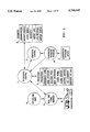
The primary Airport Control and Management (AC&M) functions of the invention utilize a cartesian ECEF X, Y, Z coordinate frame compatible with GNSS. FIG. 1 provides additional detail for the operational elements of the AC&M processing. The GNSS signals broadcast by the vehicles 8 are processed by the Real Time Communication Handler 3 and sent to AC&M Operational Control 1. The Operational Control 1 uses the GNSS data to perform the following processing functions 5: position projections, coordinate conversions, zone detection, collision prediction, runway incursion detection, layer filter, alarm control, and lighting control. If waypoints have been issued to the vehicle 8, mirrored waypoint navigation is also performed by the AC&M processing. The Operational Control 1 interfaces directly to the Graphical Control 2. Graphics messages, including GNSS data and coded information pertaining to zone incursions, possible collision conditions, or off course conditions detected by the AC&M Processing, are passed to the Graphical Control 2. The Graphical Control 2 interprets this data and updates the display presentation accordingly.
The Operational Control 1 function also receives inputs from the Controller/Operator Interface 6. The Controller/Operator Interface uses the data received by Controller/Operator Inputs 7 to compose ATC commands which are sent to the Operational Control 1 function for processing. Commands affecting the presentation on the computer display screen are sent by the Operational Control 1 function to the Graphical Control 2. ATC commands composed by the Controller/Operator Interface 6 processing that do not require further AC&M processing are forwarded directly to the Graphical Control 2 to update the display screen. Both the Operational Control 1 function and Graphical Control 2 processing have access to the Monumentation, Aircraft/Vehicle, Static Zones, Waypoints, Airport Map, ATIS Interface and Airport Status and other low level data bases 9 to process and manipulate the presentation of map and vehicle data on a computer display screen.
More specifically, each vehicle 8 supports the capability to transmit a minimum of an identifier, the GNSS referenced position of one or more antennas, velocity, optional acceleration and time reports. Since this data is broadcast, it is accessible to the airport control tower, other aircraft and vehicles in the local area, and various airline monitoring or emergency command centers which may perform similar processing functions. ATC commands, processed by the Controller/Operator Interface 6 and Operational Control 1 function are passed to the Real Time Communication Handler 3 for transmission to the aircraft/vehicle(s) 8. Upon receipt of ATC messages, the vehicle(s) 8 return an acknowledgment message which is received by the Real Time communication Handler 3 and passed to the Operational Control 1 function. Differential GNSS corrections are generated by the Differential GPS Processor 4 and passed to the Real Time Communication Handler 3 for broadcast to the vehicles. The Real Time Communication Handler 8 performs the following functions at a minimum:
a. Initialize ATC computer communication lines
b. Initialize radio equipment
c. Establish communication links
d. Receive vehicle identifier, positions, velocity, time and other information
e. Receive information from ATC Processor to transmit to vehicle(s)
f. Receive ATC acknowledgment messages from vehicle(s)
g. Transmit information to all vehicles or to selected vehicles by controlling frequency and/or identifier tags
h. Monitor errors or new information being transmitted
i. Receive and broadcast differential correction data
The AC&M techniques and methods described herein provide for GNSS compatible 4-Dimensional Airport Control and Management.
THE 3-D DIGITAL AIRPORT LAYOUT PLAN
The combination of ECEF navigation combined with NAD 83 (Lat, Lon, MSL and State Plane) and WGS 84 (X,Y,Z) based 3-D airport features are necessary in constructing an airport layout plan (ALP). The Airport Control and Management System (AC&M) requires that navigation and Automatic dependent Surveillance (ADS) information used in collision detection processing share the same coordinate frame. The processing methods described herein, require very accurate and properly monumented airport layout plans. Physical features surrounding the airport may be surveyed in a local coordinate frame and, as such, require accurate transformation into the airport map/processing coordinate frame. For these reasons, the use of multi-monumented coordinate references is mandatory for such map construction and survey. Clearly, highly accurate 3-D maps are required when using precise GNSS based navigation, collision avoidance and overall Airport Control and Management for life critical airport applications.
The 3-D ALP database and display presentation support the concept of zones. The display of zone information is managed using the Map Layer Filter. Zones are two and three dimensional shapes which are used to provide spatial cueing for a number of design constructs. Static zones may be defined around obstacles which may pose a hazard to navigation such as transmission towers, tall buildings, and terrain features. Zones may also be keyed to the airport's NOTAMS, identifying areas of the airport which have restricted usage. Dynamic zones are capable of movement. For example, a dynamic zone may be constructed around moving vehicles or hazardous weather areas. A route zone is a 3-D zone formed along a travel path such as a glide slope. Zone processing techniques are also applied to the management of travel clearances and for the detection of runway incursions. Zones may also be associated with each aircraft or surface vehicle to provide collision prediction information.
OPERATIONAL PROJECTIONS
AC&M projection processing utilizes received GNSS ADS messages from a datalink. The complete received message is then checked for errors using CRC error detection techniques or a error correcting code. The message contains the following information, or a subset thereof, but not limited to:
______________________________________                                    
PVT ADS DATA                                                              
ID #                   8 Characters                                       
VEHICLE TYPE           4 Characters                                       
CURRENT POSITION:                                                         
X = ECEF X Position (M)                                                   
                       10 Characters                                      
Y = ECEF Y Position (M)                                                   
                       10 Characters                                      
Z = ECEF Z Position (M)                                                   
                       10 Characters                                      
X2 = ECEF X2 Position (M)                                                 
                       2 Characters *                                     
Y2 = ECEF Y2 Position (M)                                                 
                       2 Characters *                                     
Z2 = ECEF Z2 Position (M)                                                 
                       2 Characters *                                     
X3 = ECEF X3 Position (M)                                                 
                       2 Characters *                                     
Y3 = ECEF Y3 Position (M)                                                 
                       2 Characters *                                     
Z3 = ECEF Z3 Position (M)                                                 
                       2 Characters *                                     
VX = ECEF X Velocity (M/S)                                                
                       4 Characters                                       
VY = ECEF Y Velocity (M/S)                                                
                       4 Characters                                       
VZ = ECEF Z Velocity (M/S)                                                
                       4 Characters                                       
AX = ECEF X Acceleration (M/S2)                                           
                       2 Characters #                                     
AY = ECEF Y Acceleration (M/52)                                           
                       2 Characters #                                     
AZ = ECEF Z Acceleration (M/S2)                                           
                       2 Characters #                                     
TIME                   8 Characters                                       
TOTAL CHARACTERS/MESSAGE:                                                 
                       80 Characters                                      
______________________________________                                    
 * OPTIONAL FIELD, FOR DETERMINING VEHICLES ATTITUDE IN 3D DIGITAL MAP DAT
 BASE                                                                     
 # OPTIONAL ACCELERATION FIELD                                            
A database is constructed using the ADS message reports. The AC&M processing converts the position and velocity information to the appropriate coordinate frame (if necessary, speed in knots and a true north heading). Simple first and second order time projections based upon position, velocity and acceleration computations are used. The ability to smooth and average the velocity information is also possible using time weighted averages.
ECEF POSITION PROJECTION TECHNIQUE
PROJECTED X=X+(VX)(t)+(AX)(t.sup.2)/2
PROJECTED Y=Y+(VY)(t)+(AY)(t.sup.2)/2
PROJECTED Z=Z+(VZ)(t)+(AZ)(t.sup.2)/2
This set of simple projection relationships is used in the collision prediction and zone incursion processing methods.
ZONE DATABASE
Zone areas may be defined in the initial map data base construction or may be added to the map database using a 2-D or 3-D data entry capability. The data entry device may be used to construct a zone using a digital map in the following manner:
Using the displayed map, the data entry device is used to enter the coordinates of a shape around the area to be designated as a zone. (An example may be a construction area closed to aircraft traffic listed in the current NOTAMS.)
The corners of the polygon are saved along with a zone type code after the last corner is entered. Circles and spheres are noted by the center point and a radius, cylinders are noted as a circle and additional height qualifying information. Other shapes are defined and entered in a similar fashion.
The zone is stored as a list of X, Y, Z coordinates. Lines connecting the points form a geometric shape corresponding to the physical zone in the selected color, line type and style in the proper layer of the base map.
Zone information may then be used by collision detection and boundary detection software contained in the AC&M system. This processing software is explained later in this specification.
FIG. 2 depicts a 3-D cylindrical static zone around a hypothetical utility pole. This zone 10 is added into the airport map 11, while the specific coordinates (center point of base 12, radius of circular base 13, and the height 14) are saved to the zone file list in a convenient coordinate frame.
Below is an example of a zone which is stored in the zone database.
______________________________________                                    
IDENTIFIER           PARAMETER                                            
______________________________________                                    
Utility pole         Type of Zone                                         
Center of base       X, Y, Z                                              
Radius of base       R                                                    
Height of the cylinder                                                    
                     H                                                    
______________________________________                                    
The 3-D digital map 11 is then updated using a series of graphic instructions to draw the zone 10 into the map with specific graphic characteristics such as line type, line color, area fill and other characteristics.
A database of zone information containing zones in surface coordinates such as X & Y state plane coordinates and mean sea level, ECEF referenced X, Y, Z and others are accessible to the AC&M Processing. The database may consist of, but is not limited to the following type of zones.
______________________________________                                    
OBJECT OF THE ZONE                                                        
______________________________________                                    
TRANSMISSION TOWERS                                                       
AIRPORT CONSTRUCTION AREAS                                                
CLOSED AREAS OF AIRPORT                                                   
MOUNTAINS                                                                 
TALL BUILDINGS                                                            
AREAS OFF TAXIWAY AND RUNWAY                                              
RESTRICTED AIRSPACE                                                       
INVISIBLE BOUNDARIES BETWEEN AIR TRAFFIC CONTROLLER                       
AREAS                                                                     
APPROACH ENVELOPE                                                         
DEPARTURE ENVELOPE                                                        
AREAS SURROUNDING THE AIRPORT                                             
MOVING ZONES AROUND AIRCRAFT/VEHICLES                                     
______________________________________                                    
ZONE PROCESSING
The zone information is retrieved from a zone database. As the AC&M Processor receives current ADS reports, information on each position report is checked for zone incursion. Further processing utilizes velocity and acceleration information to determine projected position and potential collision hazards. If a current position or projected position enters a zone area or presents a collision hazard an alert is generated.
A zone is any shape which forms a 2-D or 3-D figure such as but not limited to a convex polygon (2-D or 3-D), or a circular (2-D), spherical (3-D), cylindrical (3-D) or conical shape represented as a mathematical formula or as a series of coordinate points. Zones are stored in numerous ways based upon the type of zone. The coordinate system of the map and the units of measure greatly affect the manner in which zones are constructed, stored and processed.
The invention described herein utilizes four primary types of 2-D and 3-D zones in the Airport Control and Management System.
FOUR PRIMARY ZONE TYPES
The first type zone is a static zone as shown in FIG. 3. Static zones represent static non-moving objects, such as radio towers, construction areas, or forbidden areas off limits to particular vehicles. The zone 15 shown in the FIG. 3 represents a closed area of the airport which is under construction. The zone 15 is a 3-D zone with a height of 100 Meters 16, since it is desired not to have aircraft flying low over the construction site, but high altitude passes over the zone are permitted. An example of a permitted flyover path 17 and a forbidden fly through path 18 are shown in the figure. The fly through will produce a zone incursion, while the flyover will not.
A second zone type is shown in FIG. 4 and represents a dynamic zone 19 which moves with a moving vehicle or aircraft. Dynamic zones may be sized and shaped for rough check purposes or may be used to describe the minimum safe clearance distance. The dynamic zone is capable of changing size and shape as a function of velocity and or phase of flight and characterized by vehicle or aircraft type.
The third type of zone is shown in FIG. 5 and is a route zone 20. Route zones are described though the use of travel waypoints 21 and 22. The waypoints 21 and 22 define the center line of a travel path, the zone has a specified allowable travel radius X1, Y1 at Waypoint 1 21 and X2, Y2 at Waypoint 2 22 for the determination of on or off course processing. For simplicity X1 may equal X2 and Y1 may equal Y2. On course 23 operations result in travel which is within the zone, while off course 24 operations result in travel which is outside the zone and result in an off course warning.
The fourth type zone(s) shown in FIG. 6 is a 3-D zone which is dynamic and used to sort ATC traffic by. This type zone is used to segregate information to various types of controller/operator positions, i.e. ground control, clearance delivery, Crash Fire and Rescue and others. Travel within a particular zone automatically defines which ATC position or station the traffic is managed by. For example travel within zone 1 25 is directed to ATC ground station, while travel within zone 2 26 is directed to ATC Clearance Delivery position. The ATC zone concept allows for automatic handoff from one controllers position to the other as well as providing overall database the management automation.
The construct of zones is very important to the overall operation of the described invention herein. Further examples of zone processing methods and zone definition is provided below.
EXAMPLE 1
A cylindrical zone on the airport surface constructed using the state plane coordinate system would be represented as the following:
______________________________________                                    
Center point of circle                                                    
                CXsp value, CYsp value                                    
Elevation (MSL) Elev = constant, or may be a range                        
Circle radius   CR value                                                  
______________________________________                                    
The detection of a zone incursion (meaning that the position is within the 2-D circle) is described below.
______________________________________                                    
Convert position to State Plane coordinates                               
Current or projected position                                             
                  Xsp, Ysp                                                
Subtract circle center                                                    
                  Xsp - CXsp = DXsp                                       
from current position                                                     
                  Ysp - CYsp = DYsp                                       
Determine distance from                                                   
                  DXsp.sup.2 + Dysp.sup.2 = Rsp.sup.2                     
circle center                                                             
Test if position is in                                                    
                  Rsp <= CR                                               
circle                                                                    
                  If true continue                                        
                  If not true exit not in zone                            
Test if position is                                                       
                  Min Elev <= Elev <= Max Elev                            
within altitude range                                                     
(a cylindrical zone)                                                      
______________________________________                                    
If the above conditions are met, the position is in the 3-D cylindrical zone. It can be seen that the basic methods used here are applicable to other grid or coordinate systems based on linear distances.
EXAMPLE #2
A cylindrical zone on the airport surface (normal with the airport surface) constructed using the Earth Centered Earth Fixed coordinate system is stored using three axis (X, Y, Z).
______________________________________                                    
Convert current position to ECEF                                          
                  X, Y, Z                                                 
Center point of circle                                                    
                  CX value, CY value, CZ value                            
Circle radius     CR value                                                
Determine distance from                                                   
                  (X - CX) = DX                                           
current or projected position                                             
                  (Y - CY) = DY                                           
to center of circle                                                       
                  (Z - CZ) = DZ                                           
Determine radial distance                                                 
                  DX.sup.2 + DY.sup.2 + DZ.sup.2 = R.sup.2                
to circle center point from                                               
current position                                                          
Test position to see if it                                                
                  R <= CR                                                 
is in sphere of radius R                                                  
                  If true continue                                        
                  If not true exit not in zone                            
Determine the vector between                                              
                  VC = CXE + CYE + CZE                                    
the center of the circle                                                  
and the center of mass of                                                 
the earth                                                                 
Calculate its magnitude                                                   
                  VC.sup.2 = CXE.sup.2 + CYE.sup.2 + CZE.sup.2            
Determine the vector between the                                          
                  V = VX + VY + VZ                                        
center of mass of the earth and                                           
the current or projected position                                         
Calculate its magnitude                                                   
                  V.sup.2 = VX.sup.2 + VY.sup.2 + VZ.sup.2                
Determine the difference between                                          
                  V - VC = 0                                              
the two vectors, if result = 0                                            
then in the 2-D zone, if the result                                       
is <0 then position is below, if                                          
>0 then position is above the zone                                        
                  I                                                       
To check for incursion into an ECEF cylindrical zone, the                 
following is tested for.                                                  
Test if position is                                                       
                  Min VC <= V <= Max VC                                   
within Vector range                                                       
(a cylindrical zone)                                                      
Where        Min VC represents the bottom of the cylinder                 
             Max VC represents the top of the cylinder                    
______________________________________                                    
The final two tests use an approximation which greatly simplifies the processing overhead associated with zone incursion detection. The assumption assumes that over the surface area of an airport, the vector between the center of mass of the earth circular zone center and the vector from the current position to the center of the circle are coincident. That is, the angle between the two vectors is negligible.
The second assumption based on the first approximation is that, rather than perform complex coordinate reference transformations for zone shapes not parallel with the earth's surface, projections normal to the surface of the earth will be used. Zones which are not parallel with the earth's surface are handled in a manner similar to that applied to on or off course waypoint processing using rotation about a point or center line.
EXAMPLE #3
A zone which is shaped like a polygon is initially defined as a series of points. The points may be entered using a data entry device and a software program with respect to the digital map or they may be part of the base digital map. The points are then ordered in a manner which facilitates processing of polygon zone incursion. The following examples indicate how a (4 sided) polygon is stored and how an airport surface zone incursion is performed using both the state plane coordinates and Earth Centered Earth Fixed X, Y, Z coordinates.
______________________________________                                    
Convert Position to SP                                                    
                 Xsp, Ysp,                                                
State Plane Zone X1sp, Y1sp; X2sp, Y2sp;                                  
Vertices         X3sp, Y3sp; X4sp, Y4sp                                   
Order in a clockwise                                                      
direction                                                                 
Height of 3-D zone                                                        
                 min Elev max Elev                                        
Determine min & max                                                       
                 Xspmax, Xspmin, Yspmax, Yspmin                           
values for X & Y                                                          
Perform rough check                                                       
                 Is Xspmin <= Xsp <= Xspmax                               
of current position                                                       
                 Is Yspmin <= Ysp <= Yspmax                               
or projected position                                                     
           If both true then continue with zone checking                  
           If not true exit, not in zone                                  
Calculate the slope                                                       
                 (Y2sp - Y1sp)/(X2sp - X1sp) = M                          
of the line between                                                       
points 1 & 2                                                              
Calculate the slope of                                                    
                 Mnor = -1/m                                              
the line from the present                                                 
position normal to the                                                    
line between points 1 & 2                                                 
Determine the equation                                                    
                 Y1sp - M * X1sp = L                                      
between points 1 & 2                                                      
Determine the equation                                                    
                 Ysp - Mnor * Xsp = LN                                    
for the line normal to the                                                
line between points 1 & 2                                                 
and position                                                              
Determine the intersection                                                
                 intxsp = (LN - L)/(M - Mnor)                             
of both lines    intYsp = Mnor * intxsp +                                 
                 (Ysp - Mnor * Xsp)                                       
Determine the offset from                                                 
                 Xsp - intxsp = DXsp                                      
position to intersect                                                     
                 Ysp - intYsp = DYsp                                      
point on the line between                                                 
points 1 & 2                                                              
Perform check to see which                                                
                 Check the sign of DXsp                                   
side of the line the position is on                                       
                 Check the sign of DYsp                                   
If the point is on the proper                                             
                 Meaning the signs are                                    
side continue and check                                                   
                 o.k.                                                     
the next line between points                                              
2 & 3 and perform the same                                                
analysis                                                                  
If the line is on the wrong                                               
side of the line, then not                                                
in the zone hence exit                                                    
If point is on the proper                                                 
side of all (4) lines of polygon                                          
then in 2-D zone                                                          
Note: if the zone vertices are entered in a counter clockwise             
direction the sign of DXsp and DYsp are swapped.                          
Test if position is                                                       
                 Min Elev <= Elev <= Max Elev                             
within altitude range                                                     
(a 3-D polygon zone)                                                      
______________________________________                                    
EXAMPLE #4
A further example is provided in the definition of a 3-D runway zone using ECEF X,Y,Z. A list of runway corners is constructed using the 3-D map and a data entry device and an automated software tool. The runway zone is shown in FIG. 7.
The horizontal outline the runway 27 by selecting the four corners C1,C2,C3,C4 in a clockwise direction 28, starting anywhere on the closed convex polygon formed by the runway 27
Define the thickness of the zone (height above the runway) 29
The 4 corner 3-D coordinates and min and max altitudes are obtained through the use of a program using the ALP, then conversion are performed if necessary to convert from ALP coordinates to ECEF X, Y, Z values. ##EQU1##
MINALT=SQRT(XMIN.sup.2 +YMIN.sup.2 +ZMIN.sup.2)
MAXALT=SQRT(XMAX.sup.2 +YMAX.sup.2 +ZMAX.sup.2)
HEIGHT=MAXALT-MINALT
Define the (4) planes formed by the vectors originating at the center of mass of the earth and terminating at the respective four runway corners. Represent the 4 planes by the vector cross product as indicated below: ##EQU2##
Store the vector cross products in the polygon zones database, where the number of stored vector cross products equals the number of sides of the convex polygon
Determine if the present position or projected position is within the zone (PP=position to be checked)
PP=PX1, PY1, PZ1
Determine the scalar Dot product between the current position and the previously calculated Cross Product ##EQU3##
If the products are negative then PP is within the volume defined by intersection planes, if it is positive then outside the volume defined by the intersecting planes.
Note: the signs reverse if one proceeds around the zone in a counter clockwise direction during the definition process
Determine if PP is within the height confines of the zone
Determine the magnitude of the PP vector, for an origin at center of mass of the earth.
PPM=SQRT (PX1).sup.2 +(PY1).sup.2 +(PZ1).sup.2 !
Compare PPM=(PP magnitude) to minimum altitude of zone and maximum altitude of zone
MINALT<=PPM<=MAXALT
If the above relationship is true then in the zone.
If false then outside of the zone
An alternate method of determining if the present position PP is within a zone which is not normal to the earth's surface is determined using a method similar to that above, except that all N sides of the zone are represented as normal cross products, the corresponding Dot products are calculated and their total products inspected for sign. Based upon the sign of the product PP is either out of or inside of the zone.
An example of actual Zone and Runway Incursion software code is contained shown below. The actual code includes interfaces to light control, clearance status, tones and other ATC functions. ##SPC1##
Since the extension to polygons of N sides based upon the previous concepts are easily understood, the derivation has been omitted for the sake of brevity.
In summary two mathematical methods are identified for detecting zone incursions into convex polygons, one based on the equation and slope of the lines, the other is based on vector cross and dot product operators.
The concept of zones, regardless as to whether they are referenced to surface coordinates, local grid systems or ECEF coordinates, provide a powerful analytical method for use in the Airport Control and Management System.
ZONE BASED CLEARANCES
The airport control and management system manages overall taxi, departure and arrival clearances in a unique and novel manner through the use of zone processing. A departure ground taxi clearance is issued to the selected vehicle. The waypoints and travel path are drawn into the map aboard the selected vehicle. The vehicle(s) then use the presented taxi information to proceed to the final waypoint. AC&M processing uses this clearance information to mask runway zone incursions along the travel path. Since runway incursions are masked for only the selected vehicle and for zones traversed no runway incursion alert actions or warning lights are produced when following the proper course. Should the position represent movement outside of the established corridor, an alert is issued signifying an off course condition exist for that vehicle. Upon the vehicle exit from a particular "cleared" zone, the mask is reset for that zone. Once the last waypoint is reached the clearance is removed and the zone mask is reset. The description below details how such clearances are managed.
SURFACE DEPARTURE CLEARANCE MANAGEMENT METHOD
1. The operator or controller wishes to issue a surface departure clearance to a specific vehicle.
2. Through the use of a data entry device such as a touch screen or keyboard or mouse, issue waypoints command is selected for surface departure waypoints
3. The operator is asked to select a specific vehicle from a list of available aircraft and vehicles
4. The vehicle data window then displays a scrollable list of available vehicles contained in a database which are capable of performing operations of departure clearance
5. The operator then selects the specific vehicle using a data entry device such as a touch screen or other data entry device
6. A list is then displayed in a scrollable graphical window of available departure travel paths for the selected vehicle
7. The operator then selects from this list using a data entry device such as a touch screen or other data entry device
8. Upon selection of a particular departure path the waypoints and travel path are drawn into a 3-D ALP. The purpose of presentation is to show the controller or operator the actual path selected
9. The controller or operator is then asked to confirm the selected path. Is the selected path correct? Using a data entry device such as a touch screen or other data entry device a selection is made
10. If the selected path was not correct, then the command is terminated and no further action is taken
11. If the selection was correct the following steps are taken automatically.
a. AC&M processing sends to the selected vehicle using a radio duplex datalink, the clearance, 4-D waypoint and travel path information
b. The selected vehicle upon receipt of the ATC command replies with an acknowledgment. The acknowledgment is sent over the full duplex radio datalink to the AC&M processing
c. Should the AC&M processing not receive the acknowledgment in a specified amount of time from the selected vehicle, a re-transmission occurs up to a maximum of N re-transmissions
d. The vehicle upon receiving the ATC command then "loads" the 4-D navigator with the 4-D waypoint information. A map display contained in the vehicle then draws into the 3-D ALP the departure travel path as shown in FIG. 8. This figure shows travel path as 30 in the digital ALP 31 while actual waypoints are shown as (14) spheres 32.
DEPARTURE CLEARANCE MANAGEMENT METHOD
1. The operator or controller wishes to issue a departure clearance to a specific aircraft
2. Through the use of a data entry device such as a touch screen or keyboard or mouse, issue waypoints command is selected for departure waypoints
3. The operator is asked to select a specific vehicle from a list of available aircraft
4. The vehicle data window then displays a scrollable list of available aircraft contained in a database which are capable of performing operations of departure clearance
5. The operator then selects the specific vehicle using a data entry device such as a touch screen or other data entry device
6. A list is then displayed in a scrollable graphical window of available departure travel paths for the selected vehicle
7. The operator then selects from this list using a data entry device such as a touch screen or other data entry device
8. Upon selection of a particular departure path the waypoints and travel path are drawn into a 3-D ALP. The purpose of presentation is to show the controller or operator the actual path selected
9. The controller or operator is then asked to confirm the selected path. Is the selected path correct? Using a data entry device such as a touch screen or other data entry device a selection is made.
10. If the selected path was not correct, then the command is terminated and no further action is taken
11. If the selection was correct the following steps are taken automatically.
a. AC&M processing sends to the selected vehicle using a radio duplex datalink, the clearance, 4-D waypoint and travel path information
b. The selected vehicle upon receipt of the ATC command replies with an acknowledgment. The acknowledgment is sent over the full duplex radio datalink to the AC&M processing
c. Should the AC&M processing not receive the acknowledgment in a specified amount of time from the selected vehicle, a re-transmission occurs up to a maximum of N re-transmissions
d. The vehicle upon receiving the ATC command then "loads" the 4-D navigator with the 4-D waypoint information. A map display contained in the vehicle then draws into the 3-D ALP the departure travel path as shown in FIG. 9. This figure shows travel path as 34 in the digital ALP 35 while actual waypoints are shown as (5) spheres 36.
12. Upon AC&M receiving the acknowledgment, the following is performed:
a. the zone mask is updated indicating that the selected vehicle has a clearance to occupy runway(s) and taxiway(s) along the travel path. This mask suppresses zone runway incursion logic for this vehicle.
b. the zone based lighting control processing then activates the appropriate set of airport lights for the issued clearance in this case Take Off Lights
13. The vehicle now has active navigation information and may start to move, sending out ADS message broadcasts over the datalink to other vehicles and the AC&M system
14. The selected vehicle ADS messages are received at the AC&M system and at other vehicles.
15. AC&M processing using information contained in the ADS message performs mirrored navigational processing, as outlined in a latter section.
16. Zone incursion checking is performed for every received ADS message using position projection techniques for zones contained in the zones database
17. Should a zone incursion be detected, the zone mask is used to determine if the incurred zone is one which the vehicle is allowed to be in. If the zone is not in the zone mask then a warning is issued. Should the zone be that of a Runway, a Runway Incursion Alert is Issued and the appropriate airport lights are activated.
18. The ADS position is used to determine when the vehicle leaves a zone. When the vehicle leaves the, zone, the clearance mask is updated indicating travel though a particular zone is complete. When this occurs the following steps are initiated by the AC&M:
a. the zones mask is updated
b. airport light status is updated
If the exited zone was a Runway, operations may now occur on the exited runway
19. The vehicle continues to travel towards the final waypoint 37.
20. At the final waypoint the navigator and the map display are purged of active waypoint information, meaning the vehicle is where it is expected to be. New waypoints may be issued at any time with a waypoints command function.
AC&M zones based clearance function as presented here provides a unique and automated method for the controlling and managing airport surface and air clearances.
COLLISION DETECTION
Collision detection is performed through the zones management process. The basic steps for collision detection and avoidance are shown below in a general form. FIG. 10 shows graphically what the following text describes.
1. Vehicle Position, Velocity and Time (PVT) information are received for all tracked vehicles. The following processing is performed for each and every ADS vehicle report
2. PVT information is converted to the appropriate coordinate system if necessary and stored in the database
3. A rough check zone 38 and 39 is established based on the current velocity for each vehicle in the database
4. Every vehicle's rough check radius is compared with every other vehicle in the database. This is done simply by subtracting the current position of vehicle V from the position of vehicle V+1 in the database to determine the separation distance between each vehicle and every other vehicle in the database. This is performed in the ECEF coordinate frame.
5. For each pair of vehicles in the database that are within the sum of the two respective rough check radii values; continue further checking since a possible collision condition exists, if not within the sum of the rough check radii do no further processing until the next ADS message is received
6. For each set of vehicles which have intersecting rough check radii project the position ahead by an increment of Time (t) using the received vehicle velocity and optionally acceleration information. Projected positions at time=T1 are shown by two circles 40 and 41 the minimum safe clearance separation for the fuel truck R1 and aircraft R2 respectively.
7. Determine the new separation distance between all vehicles which initially required further checking. Compare this distance to the sum of minimum safe clearance distances R1 and R2 for those vehicles at the new incremented time. The minimum safe clearance distances R1 and R2 are contained in a database and is a function of vehicle velocity and type. Should the separation distance 42 between them be less than the sum of the minimal safe clearance distances R1+R2, then generate alert warning condition. Record the collision time values for each set of vehicles checked. If no minimum safe clearance distance is violated then continue checking the next set of vehicles in a similar fashion. When all vehicles pairs are checked then return to the start of the vehicle database.
8. Increment the projection time value (T+t) seconds and repeat step 7 if separation was greater than the sum of the minimal safe separation distance R1+R2. Continue to increment the time value to a maximum preset value, until the maximum projection time is reached, then process next pair of vehicles in a similar fashion, until the last vehicle is reached at that time start the process over. If minimum safe clearance (R1+R2) was violated compare the time of intersection to the previous time of intersection. If the previous intersection time is less than the new intersection time the vehicles are moving apart, no collision warning generated. In the event that the vehicles are moving together, meaning the intersection times are getting smaller, determine if a course change is expected based upon the current waypoints issued, and if the course change will eliminate the collision condition. If a course change is not expected or if the course change will not alleviate the collision situation then generate alert. If the projection lime T is less than the maximum projection time for warning alerts, generate a warning. If the projection time T is greater than the maximum projection time for a warning alert and less than the maximum projection time for a watch alert, generate a watch alert. If the projection time T is greater than the maximum projection time for a watch alert generate no watch alert.
9. The warning condition generates a message on the ALERT display identifying which vehicles are in a collision warning state. It also elevates the layer identifier code for those vehicle(s) to an always displayed (non-maskable) warning layer in which all potentially colliding vehicles are displayed in RED.
10. The watch condition generates a message on the ALERT display identifying which vehicles are in a collision watch state. It also elevates the layer identifier code for that vehicle(s) to an always displayed (non-maskable) watch layer in which all potentially colliding vehicles are displayed in YELLOW.
11. The process continually runs with each new ADS message report.
The sample code below performs the above collision processing, without the routine which checks for course changes, to reduce false alarms. ##SPC2##
ON OR OFF COURSE PROCESSING
The AC&M processing performs mirrored navigational processing using the same coordinate references and waypoints as those aboard the vehicles. In this manner the ATC system can quickly detect off course conditions anywhere in the 3-D airport space envelope and effectively perform zone incursion processing aboard the vehicles and at the AC&M.
The AC&M processing software converts the position and velocity information to the appropriate coordinate frame (zone & map compatible) using techniques described previously. Waypoints based upon the precise 3-dimensional map are used for surface and air navigation in the airport space envelope. The capability is provided to store waypoints in a variety of coordinate systems, such as conventional Latitude, Longitude, Mean Sea Level, State Plane Coordinates, ECEF X, Y, Z and others. The navigational waypoint and on course-off course determinations are preferred to be performed in an ECEF X, Y, Z coordinate frame, but this is not mandatory.
The following mathematical example is provided to show how waypoints and trajectories are processed in Latitude, Longitude, Mean Sea Level and in ECEF X, Y, Z. An actual GNSS flight trajectory is used for this mathematical analysis. The flight trajectory has been previously converted to an ECEF X, Y, Z format as have the waypoints using the previously described techniques. FIGS. 11, 12, 13, 14, 15 are used in conjunction with the following description.
FIG. 11 depicts the ECEF waypoint processing used in the AC&M. The ECEF coordinate system 43 is shown as X,Y,Z, the origin of the coordinate system is shown as 0,0,0. The coordinate system rotates 44 with the earth on its polar axis. The airport 45 is shown as a square patch. An enlarged side view of the airport 46 is shown with 4 waypoints 47. A further enlargement shows the Present Position 48 (PP), the Next Waypoint 49 (NWP) the Previous Waypoint (PWP) 50. The True Course Line 58 is between the Next Waypoint 49 and Previous Waypoint 50. The vector from the Present Position 48 to the Next Waypoint 49 is vector TNWP 51. The Velocity Vector 52 and Time Projected Position is shown as a solid black box 53. The Projected Position 53 is used in zone incursion processing. The 3-D distance to the true coarse is represented by the Cross Track Vector 54 XTRK. The vector normal to the earth surface at the present position and originating at the center of mass of the earth is shown as 55. This vector is assumed to be in the same direction of the vertical axis 56. The lateral axis 57 is perpendicular to the vertical axis and perpendicular to the true course line 58 between the Next Waypoint 49 and the Previous Waypoint 50. The Navigational Display 59 shows the Present Position 48 with respect to the True Course Line 58.
The following equations describe the processing performed in the AC&M while FIGS. 12, 13, 14, and 15 represent plots of the actual trajectory information.
__________________________________________________________________________
Variable Definition                                                       
T = Time in seconds                                                       
p.sub.wT = Earth's radius of curvature at the waypoint                    
Waypoint indexes through a list of waypoints                              
Waypoints are indexed as a function of position                           
Ω = the number of degrees per radian                                
                   57.295779513                                           
α = semi major axis, equatorial radius                              
                   6378137 meters                                         
e = earth's eccentricity                                                  
                   0.0818182                                              
TALT = ellipsoidal altitude of trajectory position (meters)               
WALT = ellipsoidal altitude of the waypoint positions (meters)            
ρ = earth's radius of curvature at the position or waypoint           
r = 2-d equatorial radius (meters)                                        
R = first estimate of the radius of curvature (meters)                    
sφ = the ratio of ECEF Z value divided by R (meters)                  
RC = radius of curvature at the present position (meters)                 
h = altitude with respect to the reference ellipsoid (meters)             
λ = longitude of position in radians                               
φ = latitude of position in radiams                                   
ENU = East, North, Up coordinate reference                                
XYZ = East, North, Up vector distance (meters) to waypoint                
VELENU = East, North, Up velocity in (meters/sec)                         
DISTENU = East, North, Up scalar distance to waypoint                     
VELEMUMAG = East, North, Up Velocity magnitude (scalar) meters/sec        
NBEAR = True North Bearing                                                
Position                                                                  
LA.sub.T = Latitude LO.sub.T = Longitude TALT.sub.T = MSL altitude        
Waypoint                                                                  
WLA.sub.wT = Waypoint Lat. WLO.sub.wT = Waypoint Lon. WALT.sub.wT = MSL   
altitude                                                                  
Position                                                                  
X.sub.T = ECEF X Y.sub.T = ECEF Y Z.sub.T = ECEF Z                        
Waypoint                                                                  
A.sub.T = Waypoint ECEF X  B.sub.T = Waypoint ECEF Y C.sub.T = Waypoint   
ECEF Z                                                                    
EARTH RADIUS OF CURVATURE DETERMINATION                                   
 ##STR1##                                                                 
                     ##STR2##                                             
AT WAYPOINT         AT GNSS POSITION                                      
CONVERT TRAJECTORY TO ECEF COORDINATES                                    
X.sub.T := (TALT.sub.T + ρ.sub.T) · cos(LA.sub.T) · 
cos(LO.sub.T)                                                             
Y.sub.T := (TALT.sub.T + ρ.sub.T) · cos(LA.sub.T) · 
sin(LO.sub.T)                                                             
Z.sub.T :=  TALT.sub.T + ρ.sub.T · (1 - e.sup.2)! · 
sin(LA.sub.T)                                                             
CONVERT WAYPOINTS TO ECEF COORDINATES                                     
A.sub.wT := (WALT.sub.wT + ρ.sub.wT) · cos(WLA.sub.wT)       
· cos(WLO.sub.wT)                                                
B.sub.wT := (WALT.sub.wT + ρ.sub.wT) · cos(WLA.sub.wT)       
· sin(WLO.sub.wT)                                                
C.sub.wT :=  WALT.sub.wT + ρ.sub.wT · (1 - e.sup.2)!         
· sin(WLA.sub.wT)                                                
FIND VECTOR FROM PRESENT POSITION TO NEXT WAYPOINT                        
T = TIME OF TRAJECTORY DATA MATRIX INDEX                                  
TIME INTO TRAJECTORY = 61 SECONDS                                         
CONSTRUCT ECEF WAYPOINT MATRIX Q                                          
 ##STR3##                                                                 
WAYPOINT SELECTION CRITERIA #1 TIME BASED                                 
TIME BASED WAYPOINT SELECTION TECHNIQUE                                   
DETERMINE NEXT WAYPOINT FROM PRESENT POSITION                             
 ##STR4##                                                                 
WAYPOINT SELECTION CRITERIA #2 POSITION BASED                             
UTILIZES THE CONCEPT OF ZONES, SEE ZONES                                  
 ##STR5##                                                                 
DETERMINE VECTOR BETWEEN PREVIOUS AND THE NEXT WAYPOINT                   
Qa := (Q.sub.a+1,0 - Q.sub.a,0 Q.sub.a+1,1 - Q.sub.a,1 Q.sub.a+1,2 -      
Q.sub.a,2)                                                                
PP := (X.sub.T Y.sub.T Z.sub.T)  PRESENT POSITION                         
NWP :=  A.sub.N·(1+a) B.sub.N·(1+a) C.sub.N·(1+
a) !  NEXT WAYPOINT                                                       
TNWP := NWP - PP  VECTOR DISTANCE TO THE NEXT WAYPOINT                    
AT FLIGHT TIME T = 61 SECONDS, THE NEXT WAYPOINT IS THE FOLLOWING         
X, Y, Z DISTANCE FROM THE CURRENT POSITION                                
TNWP = (-394.0104406164 424.5394341322 588.6638708804)                    
DETERMINE THE MAGNITUDE OF THE DISTANCE TO THE WAYPOINT                   
 ##STR6##                                                                 
DIST = 825.8347966318 METERS                                              
NEXT DETERMINE IF THE SPEED SHOULD REMAIN THE SAME, OR CHANGE             
TIME EXPECTED AT NEXT WAYPOINT IS 80 SECONDS INTO TRAJECTORY              
CURRENT VELOCITY IS BASED UPON GNSS RECEIVER DETERMINATION                
 ##STR7##                                                                 
VX = -20.7373916114 M/S × ECEF VELOCITY TO REACH WAYPOINT ON TIME   
COMPARE CURRENT X VELOCITY TO REQUIRED X VELOCITY, IF LESS INCREASE       
IN VELOCITY, IF GREATER THAN REQUIRED VELOCITY DECREASE VELOCITY          
 ##STR8##                                                                 
VY = 22.3441807438 M/S Y ECEF VELOCITY TO REACH WAYPOINT ON TIME          
COMPARE CURRENT Y VELOCITY TO REQUIRED Y VELOCITY, IF LESS INCREASE       
IN VELOCITY, IF GREATER THAN REQUIRED VELOCITY DECREASE VELOCITY          
 ##STR9##                                                                 
VZ = 30.9823089937 M/S Z ECEF VELOCITY TO REACH WAYPOINT ON TIME          
COMPARE CURRENT Z VELOCITY TO REQUIRED Z VELOCITY, IF LESS INCREASE       
IN VELOCITY, IF GREATER THAN REQUIRED VELOCITY DECREASE VELOCITY          
 ##STR10##                                                                
VELECEF = 43.4649892964 M/S                                               
VELECEF = (-20.737 22.344 30.982)                                         
DETERMINE THE ON COURSE OFF COURSE NAVIGATIONAL DATA                      
UNIT VECTOR PERPENDICULAR TO PLANE OF QA AND TNWP                         
 ##STR11##                                                                
                     ##STR12##                                            
UNIT VECTOR PERPENDICULAR TO PLANE OF QA AND NP                           
 ##STR13##                                                                
                     ##STR14##                                            
CROSS TRACK ERROR                                                         
XTRK := UN · TNWP.sup.T                                          
XTRK = 28.5392020973                                                      
CALCULATE CROSS TRACK VECTOR                                              
 VXTRK := XTRK · UN                                              
                     ##STR15##                                            
UNIT VECTOR FROM PRESENT POSITION TO NEXT WAYPOINT                        
 ##STR16##                                                                
                     ##STR17##                                            
UNIT VECTOR OF PRESENT POSITION                                           
 ##STR18##                                                                
                     ##STR19##                                            
UNIT VECTOR OF NEXT WAYPOINT                                              
 ##STR20##                                                                
                     ##STR21##                                            
CHECK AGAINST GREAT CIRCLE TECHNIQUE                                      
GREAT CIRCLE ANGLE β := acos(UNWP · UPP) β ·  
Ω = 0.0074290102 DEGREES                                            
DETERMINE RANGE TO NEXT WAYPOINT FROM PRESENT POSITION h = 0              
SHOULD BE THE SAME AS DIST WHEN ALT IS NEARLY AT ELLIPSOID                
 ##STR22##                                                                
`THE ECEF ANALYSIS COMPARES TO GREAT CIRCLE ANALYSIS VERY CLOSELY`        
CONVERTING BACK TO LAT. LON AND MSL                                       
DETERMINE GEODETIC PARAMETERS (LAT, LON & EL)                             
 ##STR23##                                                                
               ##STR24##                                                  
                               ##STR25##                                  
 ##STR26##                                                                
               ##STR27##      h = 287.6967718417                          
 ##STR28##                                                                
               ##STR29##      λ · Ω = -71.40645     
                              φ · Ω = 42.930575339     
CONVERT TO ENU COORDINATES                                                
 ##STR30##                                                                
FIND ENU VECTOR FROM PRESENT POSITION TO NEXT WAYPOINT                    
EAST DISTANCE                                                             
NORTH DISTANCE                                                            
UP DISTANCE                                                               
 ##STR31##                                                                
                     ##STR32##                                            
EAST VEL.                                                                 
NORTH VEL.                                                                
UP VEL.                                                                   
 ##STR33##                                                                
                     ##STR34##                                            
 ##STR35##                                                                
DIST = 825.8347966318 METERS                                              
 ##STR36##                                                                
VELENUMAG = 43.4644892872 M/S                                             
THE ECEF APPROACH AND THE ENU APPROACH PRODUCE THE SAME                   
RESULTS SO IT IS POSSIBLE TO USE EITHER COORDINATE REFERENCE TO           
CONTROL THE NECESSARY SPEED TO THE WAYPOINT                               
FIND TRUE NORTH BEARING ANGLE TO NEXT WAYPOINT USING TANGENT              
 ##STR37##                                                                
ADJUST FOR TRIGONOMETRIC QUADRANTS AND YOU HAVE THE TRUE                  
__________________________________________________________________________
BEARING                                                                   
Should the Range to the Waypoint become larger than the previous range of the waypoint a waypoint may not have automatically indexed. This situation could occur if the vehicle did not get close enough to the waypoint to index automatically or an ADS message may have been garbled and the waypoint did not index, due to a lost ADS message. In this case the following analysis is performed:
a) temporarily increment the waypoint index
b) find the vector between the vehicles present position (PP) and the next waypoint (NWP)
Vector to the next waypoint, TNWP=NWP(X,Y,Z)-PP(X,Y,Z)
c) Determine the current vehicle velocity vector
VEL=(VX,VY,VZ)
d) Determine the Dot Product between the Velocity Vector and Vector TNWP
COS θ=TNWP dot VEL
e) If A<COS θ<B then keep current waypoint index
Where A and B are between 0 and 1 and represent an adjustable value based on the allowable vehicle velocity angular deviation from the true course
If -1<COS θ<=0 then return to previous waypoint index and generate wrong way alert
The above technique can be expanded to in&& curved approach, using cubic splines to smooth the transitions between waypoints. A curved trajectory requires changes to the above set of equations. Using the technique of cubic splines, one can calculate three cubic equations which describe smooth (continuous first and second derivatives) curves through the three dimensional ECEF waypoints. The four dimensional capability is possible when the set of cubic equations is converted into a set of parametric equations in time. The table below depicts an ECEF waypoint matrix which is used in cubic spline determinations.
Waypoint Matrix (SEE Q MATRIX) Typical Waypoint ECEF Matrix
The AC&M processing utilizes the combination of precise ECEF X, Y, Z navigation and waypoints. Waypoints may be stored in a data file for a particular runway approach, taxi path or departure path. Waypoints may be entered manually, through the use of a data entry device. A list of waypoints describing a flight and or taxi trajectory is then assigned to a particular vehicle. To further supplement waypoint processing expected arrival time may be added to each waypoint as well as velocity ranges for each phase of flight. In this manner, 4 dimensional airport control and management is provided utilizing a GNSS based system. Mathematical processing is used in conjunction with precise waypoints to define flight trajectories. The mathematics typically uses cylindrical shapes but is not limited to cylinders, cones may also be used, and are defined between adjacent waypoints. Typical on or off course processing is outlined below and is shown in FIG. 16.
EXAMPLE 1 MISSED WAYPOINT, WITH OFF COURSE CONDITION
a. Construct the True Course line between the previous waypoint 61 and the next waypoint 62
b. Determine the shortest distance (cross track error 64) from the current position 63 to the line 60 between the previous waypoint 61 and next waypoint 62
c. Determine the magnitude of cross track error
d. Compare the magnitude of the cross track error to a predefined limit for total off course error shown as 65 in the figure.
e. Construct an mathematical cylindrical zone centered on the line between the previous 61 and next waypoint 62 with radius equal to the off course threshold 65.
f. If the magnitude of the cross track error 64 is greater than the off course threshold 65 then raise flag and generate alert (off course).
g. Determine the necessary velocity to reach next waypoint on schedule, as shown previously
h. Is necessary velocity within preset limits or guidelines?
i. Check actual current velocity against preset limits and necessary velocity, If above preset limits, raise flag and issue alert to slow down. If below preset limits, raise flag and issue alert to speed up
j. Automatically index to the following waypoint 66 when the position is within the index waypoint circle 67
k. Should wrong way be detected (positions 68 and 69), index ahead to the next to waypoint pair 66 and 62 and check direction of travel 71 (Velocity) against the line 72 between the waypoints 66 and 62, if the direction of travel is within a preset angular range 70 (A to B degrees) and not off course. If the cheek is true meaning not off course and headed towards next waypoint then index permanently to waypoint set 66 and 62, no alert generated
l. In the event that an off course condition and wrong way occur (position 69) a message is formatted which updates the layer filter for the target which is off course, an alert is generated, the waypoints are returned to the initial settings and action is taken to bring vehicle back on course possibly using a set of new waypoints
m. In the event of a velocity check which indicates that the speed up or slow down velocity is outside of an approved range, generate a warning the speed for vehicle is out of established limits, Preset speed over ground limits are adjusted for current air wind speed.
n. The controller reviews the situation displayed and if necessary invokes a navigational correction message to be sent to the Real Time Communication Handler, and then broadcast by radio to the aircraft off course or flying at the wrong speed. The controller at this time may change the expected arrival time at the next waypoint if so necessary
EXAMPLE 2 MISSED WAYPOINT, WITH ON COURSE PROCESSING
a. Construct the True Course line between the previous waypoint 66 and the next waypoint 72
b. Determine the shortest distance (cross track error 73) from the current position 74 to the line between the previous waypoint 66 and next waypoint 72
c. Determine the magnitude of cross track error
d. Compare the magnitude of the cross track error to a predefined limit for total off course error shown as 75 in the figure.
e. Construct an mathematical cylindrical zone centered on the line between the previous waypoint 66 and next waypoint 72 with radius equal to the off course threshold 75
f. If the magnitude of the cross track error 73 is greater than the off course threshold 75 then raise flag and generate alert (off course).
g. Determine the necessary velocity to reach next waypoint on schedule, as shown previously
h. Is necessary velocity within preset limits or guidelines?
i. Check actual current velocity against preset limits and necessary velocity, If above preset limits, raise flag and issue alert to slow down. If below preset limits, raise flag and issue alert to speed up
j. Automatically index to the following waypoint 76 when the position is within the index waypoint circle 77
k. Should wrong way be detected (position 74), index ahead to the next to waypoint pair 76 and 72 and check direction of travel 78 (Velocity) against the the line 80 between the waypoints 76 and 72, if the direction of travel is within a preset angular range 79 (A to B degrees) and not off course. If the check is true meaning not off course and headed towards next waypoint then index permanently to waypoint set 76 and 72, no alert generated
l. In the event of a velocity check which indicates that the speed up or slow down velocity is outside of an approved range, generate a warning the speed for vehicle is out of established limits, Preset speed over ground limits are adjusted for current air wind speed.
m. The controller reviews the situation displayed and if necessary invokes a navigational correction message to be sent to the Real Time Communication Handler, and then broadcast by radio to the aircraft off course or flying at the wrong speed. The controller at this time may change the expected arrival time at the next waypoint if so necessary
The AC&M processing performs all on or off course processing determinations and the displays information related to on or off course or late or early arrival conditions. While FIG. 17 summarizes speed up-slow down information in graphical form 80 and distance to the waypoint 81 from an actual GNSS landing. The neutral line 82 labelled "0" translates to no velocity change is necessary to reach next waypoint on time.
ALERT DISPLAY FUNCTION
Within the AC&M system collision alerts, zone, off course and improper speed warnings are handled somewhat differently than normal position updates. When the AC&M processing recognizes a warning condition, the aircraft(s)/vehicle(s) involved are moved to a special ALP layer. The layer filter controls what graphic parameters a particular vehicle or aircraft is displayed with. The change in the layer from the default vehicle layer signifies that the target has been classified as a potential collision, zone intrusion risk, off course condition or improper speed.
AC&M CONTROL ZONES
ATC Control Zones are used to sort and manage air and surface traffic within the airport space envelope. The AC&M Control Area is divided into AC&M Control Zones. Typically the outer most airport control zone interfaces with an en route zone. Aircraft within the 3-D AC&M zone transmit their GNSS derived positions via an on board datalink. The GNSS data is received by the airport AC&M equipment. The AC&M Processing determines the ECEF AC&M Control Zone assignment based on the aircraft's current position and assigns the aircraft to the map layer associated with that Control Zone. Mathematical computations as defined previously, are used to determine when a vehicle is in a particular control zone.
As an aircraft enters the AC&M or transitions to another ATC Control Zone, a handoff is performed between the controllers passing and receiving control of that aircraft. Surface traffic is handled in the same manner. With this AC&M scenario, each controller receives all target information but suppresses those layers that are not under his control. In this manner the controller or operator views on those vehicles or aircraft in his respective control zone. Should there be a collision condition across an ATC zone boundary the conflicting vehicles will be displayed in a non-surpressable layer.
All targets within an AC&M Control Zone would be placed in the appropriate map layer for tracking and display purposes. Layer coding for each tracked target can be used to control graphic display parameters such as line type, color, line width as well as be used as a key into the underlying database for that object.
Additional AC&M Control Zones may be defined for other surface areas of the airport, such as construction areas, areas limited to specific type of traffic, weight limited areas and others. These areas may be handled through ATC but will most likely be controlled by airline or airport maintenance departments. The concept of a zone based AC&M system integrated with 3-D map information provides a valuable management and navigational capability to all vehicles and aircraft within the airport space envelope.
ENTERING WAYPOINTS
The AC&M processing defined herein allows the user to enter waypoints using the digital map as a guide. To enter a series of waypoints the controller simply uses the map which may provide plan and side views of the airport space envelope. The cursor is moved to the appropriate point and a selection is made by pressing a key. The position is then stored in a list with other waypoints entered at the same time. The user is then prompted to enter a name for the waypoint list and an optional destination. Lastly, the waypoints converted the appropriate coordinate frame and are then saved to a file or transmitted to a particular vehicle. In this manner the user may add and define waypoints.
DEFINING ZONES
The user may define zones using the digital map as a guide. To enter a series of zones the controller simply uses the map which may provide plan and side views of the airport space envelope. The cursor is moved to the appropriate point and a selection is made by pressing a key. The position is then stored in a list with other zone definition points. The controller is then prompted to enter a name for the zone (pole, tower, construction area, etc.) and type of zone (circle, sphere, box, cylinder, etc.). Lastly, the zones are converted to the appropriate coordinate frame and saved to a file or transmitted to a particular vehicle. In this manner the user may define additional zones.
The ability to quickly and accurately define zones is key to the implementation of a zones based AC&M capability. It is obvious that minor changes may be made in the form and construction of the invention without departing from the material spirit thereof. It is not, however, desired to confine the invention to the exact form herein shown and described, but is desired to include all such as properly come within the scope claimed.

Claims (11)

The invention having thus been described, and what is claimed as new and desired to secure by Letters of Patent is:
1. A method for GNSS compatible traffic management using a computer system incorporating zone incursion processing located on a vehicle including aircraft and surface vehicular equipment, said method comprising the steps of:
a. adopting a coordinate reference system for processing by said computer system, where said adopted coordinate reference system is the Earth Centered Earth Fixed coordinate reference;
b. selecting a geographical region for said traffic management; said selected region being referenced to said adopted coordinate reference system;
c. establishing a static zones database, for said selected region, said static zones database containing descriptive data representing selected spatial characteristics referenced to said adopted coordinate reference system;
d. determining GNSS position data of said vehicle;
e. establishing a vehicle database, said vehicle database containing said position data referenced to said adopted coordinate reference system;
f. determining if said position data of said vehicle database incur a static zone, said static zone being defined within said static zones database; and
g. enabling a static zone incursion flag for said vehicle if said position data incur said static zone of said static zones database thereby making a static zone incursion alert.
2. The method for traffic management according to claim 1 further comprising: generating incursion alerts, said generation of incursion alerts comprising the steps of:
establishing a travel path waypoints database, said travel path waypoints database containing waypoints referenced to said adopted coordinate reference system;
b. generating for said vehicle an assigned travel path, selected from said travel path waypoints database;
c. enabling said static zone incursion flag for static zones not intersecting said assigned travel path; and
d. generating a static zone incursion alert for said vehicle when said vehicle position incurs a static zone of said static zone database with said static zone incursion flag enabled.
3. A method for traffic management according to claim 2 further comprising, masking generation of false static zone incursion alerts, said masking generation of false static zone incursion alerts comprising the steps of;
a. disabling said static zone incursion flag for static zones intersecting said assigned travel path, thereby masking the generation of said false static zone incursion alerts along said assigned travel path.
4. A method for GNSS compatible on and off course processing traffic management using a computer system located aboard a vehicle, said vehicle including aircraft and surface vehicular equipment, said method comprising the steps of:
a. adopting a coordinate reference system for processing by said computer system, where said adopted coordinate reference system is the GNSS Earth Centered Earth Fixed coordinate reference;
b. selecting a geographical region for said traffic management, said selected region being referenced to said adopted coordinate reference system;
c. establishing a travel path waypoints database for said region, said waypoints database containing descriptive data representing waypoint characteristics referenced to said adopted coordinate reference system;
d. determining GNSS position data of said vehicle;
e. establishing a vehicle database, said vehicle database containing said position data referenced to said adopted coordinate reference system;
f. generating for said vehicle an assigned travel path selected from said waypoints database;
g. determining the previous and next waypoints along said assigned travel path;
h. establishing for said vehicle, a route zone for said assigned travel path, using said previous and next waypoints;
i. determining if said vehicle position data contained in said vehicle database is outside of said route zone; and
j. setting for said vehicle an off course flag when said position data of said vehicle database is outside of said route zone, thereby making an off course alert when said vehicle is off course.
5. A method for GNSS compatible vehicle traffic management according to claim 4 utilizing wrong way monitoring, said method further comprising the steps of:
a. determining a true course vector to said next waypoint from said position data contained in said vehicle database;
b. determining a velocity vector of said vehicle in said adopted coordinate reference system;
c. determining the angle between said true course vector and said velocity vector; and
d. setting for said vehicle a wrong way flag if said angle is not within a specified acceptable numerical range, thereby generating an alert for said vehicle when said vehicle is traveling in the wrong direction.
6. The method for traffic management according to claim 5 further comprising; the step of disabling said off course alert if said position data for said vehicle contained in said vehicle database is outside of said route zone and said vehicle wrong way flag is not set.
7. The method for vehicle traffic management according to claim 5 further comprising:
a. determining the range to said next waypoint from said position data in said vehicle database; and
b. incrementing automatically to the next waypoint pair in said waypoints database when said range to said next waypoint is within a predetermined distance.
8. The method for traffic management according to claim 5 further comprising reducing incidence of wrong way false alerts, said reducing incidence of wrong way false alerts comprising the steps of;
a. incrementing to the next pair of previous and next waypoints contained in said waypoints database when said wrong way flag is set;
b. determining the current GNSS position and a previous position for said vehicle using said vehicle database, wherein said current position becomes said previous position upon the receipt of a new position in said vehicle database, and said new position becoming said current position;
c. determining the current distance to said next waypoint from said current position when said wrong way flag is set;
d. determining the previous distance to said next waypoint from said previous position when said wrong way flag is set;
e. comparing said previous distance to said current distance; and
f. clearing said vehicle wrong way flag when said current distance is smaller than said previous distance.
9. A method for GNSS compatible vehicle traffic management using a computer system located on a vehicle, incorporating collision detection processing between at least two vehicles of a plurality of vehicles, said plurality of vehicles including aircraft and surface vehicular equipment said method comprising the steps of:
a. adopting a coordinate reference system for processing by said computer system, where said adopted coordinate reference system is the GNSS Earth Centered Earth Fixed coordinate reference;
b. selecting a geographical region for said traffic management, said selected region being referenced to said adopted coordinate reference system;
c. establishing a vehicle database, said vehicle database containing identification, position and velocity information, determining a time of applicability for said position and velocity information which is referenced to said adopted coordinate reference system for said at least two vehicles operating in said selected region;
d. determining a type classification for said at least two vehicles using said identification information contained in said vehicle database;
e. determining a manner of movement and operation for said at least two vehicles, using said information contained in said vehicle database;
f. constructing for said at least two vehicles dynamic zones, wherein each of said dynamic zones is sized based on said type classification and said manner of movement and operation of said at least two vehicles using said identification, position and velocity information in said vehicle database;
g. generating time-based projected positions for said at least two vehicles using said vehicle database;
h. generating projected dynamic zones for said at least two vehicles using said projected positions;
i. determining if at least two of said projected dynamic zones intersect; and
j. setting a collision flag for at least one of said at least two vehicles having said projected dynamic zones intersect with at least one other projected dynamic zone thus generating an alert indicating a potential collision condition.
10. A method for GNSS compatible vehicle traffic management using a computer system located on a vehicle, incorporating speed up or slow down indicators for vehicles including aircraft and surface vehicular equipment, said method comprising the steps of:
a. adopting a coordinate reference system for processing by said computer system, where said adopted coordinate reference system is the GNSS Earth Centered Earth Fixed coordinate reference;
b. selecting a geographical region for said traffic management, said selected region being referenced to said adopted coordinate reference system;
c. establishing a travel path waypoints database for said selected geographical region, said travel path waypoints containing waypoints referenced to said adopted coordinate reference system where said waypoints include a position with an arrival time;
d. determining GNSS position data of said vehicle;
e. establishing a vehicle database, said vehicle database containing said position data referenced to said adopted coordinate reference system for said vehicle operating in said selected region;
f. generating for said vehicle an assigned travel path selected from said travel path waypoints database;
g. determining previous and next waypoints with desired arrival times along said assigned travel path;
h. determining for said vehicle a distance from the current position to the next waypoint;
i. establishing a current time;
j. determining a remaining time for said vehicle to reach said next waypoint by subtracting said current time from said desired arrival time associated with said next waypoint;
k. calculating for said vehicle a necessary velocity to reach said next waypoint at said desired arrival time, by dividing said distance by said remaining time;
l. determining the current velocity of said vehicle;
m. comparing said necessary velocity to said current velocity;
n. providing for said vehicle increase or decrease velocity guidance based upon said comparing of said necessary velocity to said current velocity.
11. The method for traffic management according to claim 10 further comprising generating velocity warnings, said generating velocity warnings comprising the steps of:
a. establishing a database of desired velocity ranges for various manner of movements,
b. determining the current manner of movement of said vehicle;
c. selecting a desired velocity range for said vehicle, based upon said current manner of movement, from said database of desired velocity ranges;
d. comparing said current velocity to said selected desired velocity range; and
e. generating a velocity alert when said current velocity of said vehicle is outside said selected desired velocity range.
US08/651,837 1990-10-09 1996-05-21 GNSS based, seamless, multi-dimensional control and management system for vehicles operating in a multi-dimensional environment Expired - Lifetime US5740047A (en)

Priority Applications (4)

Application Number Priority Date Filing Date Title
US08/651,837 US5740047A (en) 1990-10-09 1996-05-21 GNSS based, seamless, multi-dimensional control and management system for vehicles operating in a multi-dimensional environment
US09/304,037 US6182005B1 (en) 1990-10-09 1999-05-03 Airport guidance and safety system incorporating navigation and control using GNSS compatible methods
US09/871,328 US20030083804A1 (en) 1990-10-09 2001-05-31 Computer human methods for the control and management of an airport
US10/733,968 US20040225432A1 (en) 1991-02-25 2003-12-11 Method and system for the navigation and control of vehicles at an airport and in the surrounding airspace

Applications Claiming Priority (4)

Application Number Priority Date Filing Date Title
US07/593,214 US5200902A (en) 1990-10-09 1990-10-09 Airport control/management system
US75885291A 1991-09-12 1991-09-12
US08/117,920 US5548515A (en) 1990-10-09 1993-09-07 Method and system for airport control and management
US08/651,837 US5740047A (en) 1990-10-09 1996-05-21 GNSS based, seamless, multi-dimensional control and management system for vehicles operating in a multi-dimensional environment

Related Parent Applications (2)

Application Number Title Priority Date Filing Date
US08/117,920 Continuation US5548515A (en) 1990-10-09 1993-09-07 Method and system for airport control and management
US08/369,273 Continuation-In-Part US5574648A (en) 1990-10-09 1995-01-05 Airport control/management system using GNSS-based methods and equipment for the control of surface and airborne traffic

Related Child Applications (3)

Application Number Title Priority Date Filing Date
US08/117,920 Continuation-In-Part US5548515A (en) 1990-10-09 1993-09-07 Method and system for airport control and management
US09/598,001 Continuation-In-Part US6314363B1 (en) 1990-10-09 2000-06-20 Computer human method and system for the control and management of an airport
US09/598,001 Division US6314363B1 (en) 1990-10-09 2000-06-20 Computer human method and system for the control and management of an airport

Publications (1)

Publication Number Publication Date
US5740047A true US5740047A (en) 1998-04-14

Family

ID=27081648

Family Applications (2)

Application Number Title Priority Date Filing Date
US08/117,920 Expired - Lifetime US5548515A (en) 1990-10-09 1993-09-07 Method and system for airport control and management
US08/651,837 Expired - Lifetime US5740047A (en) 1990-10-09 1996-05-21 GNSS based, seamless, multi-dimensional control and management system for vehicles operating in a multi-dimensional environment

Family Applications Before (1)

Application Number Title Priority Date Filing Date
US08/117,920 Expired - Lifetime US5548515A (en) 1990-10-09 1993-09-07 Method and system for airport control and management

Country Status (5)

Country Link
US (2) US5548515A (en)
EP (1) EP0592436A1 (en)
AU (1) AU8877991A (en)
CA (1) CA2070840A1 (en)
WO (1) WO1992006442A1 (en)

Cited By (55)

* Cited by examiner, † Cited by third party
Publication number Priority date Publication date Assignee Title
US5890079A (en) * 1996-12-17 1999-03-30 Levine; Seymour Remote aircraft flight recorder and advisory system
US5926117A (en) * 1997-06-10 1999-07-20 Hitachi, Ltd. Vehicle control system, vehicle mounting apparatus, base station apparatus and vehicle control method
US6043756A (en) * 1998-02-09 2000-03-28 Alliedsignal Inc. Aircraft weather information system
US6085147A (en) * 1997-09-26 2000-07-04 University Corporation For Atmospheric Research System for determination of optimal travel path in a multidimensional space
US6144915A (en) * 1997-03-26 2000-11-07 Director-General, Ship Research Institute, Ministry Of Trans Aerodrome control support system
US6161097A (en) * 1997-08-11 2000-12-12 The United Sates Of America As Represented By The Administrator Of The National Aeronautics And Space Administration Automated traffic management system and method
US6195609B1 (en) * 1993-09-07 2001-02-27 Harold Robert Pilley Method and system for the control and management of an airport
US6259976B1 (en) 1999-09-25 2001-07-10 Jerome H. Lemelson Fuzzy logic based emergency flight control with thrust vectoring
US6278965B1 (en) 1998-06-04 2001-08-21 The United States Of America As Represented By The Administrator Of The National Aeronautics And Space Administration Real-time surface traffic adviser
EP1187008A2 (en) * 2000-04-10 2002-03-13 Teledyne Technologies Incorporated System and method for specification of trigger logic conditions
US6456941B1 (en) 2001-03-26 2002-09-24 William Gutierrez System and method for aircraft and watercraft control and collision prevention
EP1265078A2 (en) * 2001-06-06 2002-12-11 Marconi Mobile SpA Improvements in or relating to obstacle advisory systems
US6498981B1 (en) * 1999-12-30 2002-12-24 Honeywell International Inc. System for sequencing traffic
US6584400B2 (en) 2001-04-09 2003-06-24 Louis J C Beardsworth Schedule activated management system for optimizing aircraft arrivals at congested airports
US6606563B2 (en) * 2001-03-06 2003-08-12 Honeywell International Inc. Incursion alerting system
US20030154027A1 (en) * 2000-05-17 2003-08-14 Omega Patents, L.L.C. Vehicle tracker including input/output features and related methods
US20030167109A1 (en) * 2002-02-28 2003-09-04 Clarke Michael D. D. Methods and systems for routing mobile vehicles
US6650360B1 (en) * 1993-12-23 2003-11-18 Wells & Verne Investments Limited Camera guidance system
WO2003107299A2 (en) * 2002-04-01 2003-12-24 Ryan International Corporation Method and device for protection against runway incursions
US6748325B1 (en) 2001-12-07 2004-06-08 Iwao Fujisaki Navigation system
US20040145499A1 (en) * 2003-01-29 2004-07-29 Schmidt Noel E. Runway occupancy monitoring and warning
US6772140B1 (en) 1999-11-01 2004-08-03 Harris-Exigent, Inc. Hierarchical syntax for satellite command and control directives
US20040225440A1 (en) * 2001-03-06 2004-11-11 Honeywell International, Inc. Ground runway awareness and advisory system
US20050015202A1 (en) * 2002-05-15 2005-01-20 Honeywell International, Inc. Ground operations and advanced runway awareness and advisory system
US20050128129A1 (en) * 2001-03-06 2005-06-16 Honeywell International, Inc. Ground operations and imminent landing runway selection
US20050200501A1 (en) * 1999-03-05 2005-09-15 Smith Alexander E. Aircraft boundary transition warnings and auto alerting
US20060007021A1 (en) * 2004-07-12 2006-01-12 Kazuhide Konya Systems and methods for collision avoidance
US20060064245A1 (en) * 2004-09-20 2006-03-23 Gilbert Eric B Vehicle collision shield
US7027719B1 (en) 1999-10-08 2006-04-11 Raytheon Company Catastrophic event-survivable video recorder system
US7194358B2 (en) 2004-02-25 2007-03-20 The Boeing Company Lift collision avoidance system
US20070126621A1 (en) * 2005-12-02 2007-06-07 The Boeing Company Seamless Air Traffic Control (ATC) Datalink Transfers
US20070138347A1 (en) * 2004-12-16 2007-06-21 Ehlers Gregory A System and method for providing information to an operator of a vehicle
US20070250260A1 (en) * 2006-04-25 2007-10-25 Honeywell International Inc. Method and system for autonomous tracking of a mobile target by an unmanned aerial vehicle
US20080040023A1 (en) * 1997-10-22 2008-02-14 Intelligent Technologies International, Inc. Intra-Vehicle Information Conveyance System and Method
US20080140269A1 (en) * 2006-12-06 2008-06-12 Universal Avionics Systems Corporation Aircraft ground maneuvering monitoring system
WO2008142271A2 (en) * 2007-04-16 2008-11-27 Airbus France Aircraft navigation aid device
US20090115637A1 (en) * 2006-12-06 2009-05-07 Joachim Laurenz Naimer Aircraft-centered ground maneuvering monitoring and alerting system
US20100063716A1 (en) * 2006-11-24 2010-03-11 Raimund Brozat Method and device for the control of air traffic management at an airport
US20100127895A1 (en) * 2008-11-24 2010-05-27 Honeywell International Inc. System and method for displaying graphical departure procedures
US20110032124A1 (en) * 2009-08-10 2011-02-10 John Baskin Taxiway aircraft location monitoring system
US20110221615A1 (en) * 2008-11-25 2011-09-15 Sandy Sanderson Chiu System and Method for Informing Public Transport Vehicle Arrival Information
US8145367B2 (en) 2001-03-06 2012-03-27 Honeywell International Inc. Closed airport surface alerting system
US8886445B1 (en) * 2010-03-05 2014-11-11 The United States Of America As Represented By The Administrator Of The National Aeronautics And Space Administration Automatic aircraft collision avoidance system and method
US8965677B2 (en) 1998-10-22 2015-02-24 Intelligent Technologies International, Inc. Intra-vehicle information conveyance system and method
US20150102954A1 (en) * 2013-10-13 2015-04-16 Lang Hong 4-dimensional continuous wave radar system for traffic safety enforcement
US20160086496A1 (en) * 2014-09-23 2016-03-24 Raytheon Company Runway incursion detection and indication using an electronic flight strip system
US9537956B1 (en) * 2015-12-11 2017-01-03 Uber Technologies, Inc. System for acquiring time-synchronized sensor data
US9596666B1 (en) 2015-12-11 2017-03-14 Uber Technologies, Inc. System for processing asynchronous sensor data
US9785150B2 (en) 2015-12-11 2017-10-10 Uber Technologies, Inc. Formatting sensor data for use in autonomous vehicle communications platform
WO2017196213A1 (en) 2016-05-11 2017-11-16 Telefonaktiebolaget Lm Ericsson (Publ) Remote control of an unmanned aerial vehicle
US9939522B2 (en) 2013-10-13 2018-04-10 Oculii Corp Systems and methods for 4-dimensional radar tracking
US10101747B2 (en) 2015-12-11 2018-10-16 Uber Technologies, Inc. Formatting sensor data for use in autonomous vehicle communications platform
US10114103B2 (en) 2016-03-31 2018-10-30 Uber Technologies, Inc. System and method for sensor triggering for synchronized operation
US10482559B2 (en) 2016-11-11 2019-11-19 Uatc, Llc Personalizing ride experience based on contextual ride usage data
US11383963B2 (en) 2017-03-03 2022-07-12 Jlg Industries, Inc. Obstacle detection system for an aerial work platform

Families Citing this family (100)

* Cited by examiner, † Cited by third party
Publication number Priority date Publication date Assignee Title
US6006158A (en) * 1993-09-07 1999-12-21 H. R. Pilley Airport guidance and safety system incorporating lighting control using GNSS compatible methods
US5867804A (en) * 1993-09-07 1999-02-02 Harold R. Pilley Method and system for the control and management of a three dimensional space envelope
JP3220807B2 (en) * 1991-11-20 2001-10-22 三和シヤッター工業株式会社 Architectural shutter
US10361802B1 (en) 1999-02-01 2019-07-23 Blanding Hovenweep, Llc Adaptive pattern recognition based control system and method
US8352400B2 (en) 1991-12-23 2013-01-08 Hoffberg Steven M Adaptive pattern recognition based controller apparatus and method and human-factored interface therefore
US5343395A (en) * 1992-08-26 1994-08-30 Watts Alan B Aircraft landing guidance system and method
AU774453B2 (en) * 1992-10-15 2004-06-24 Mobile Information Systems, Inc. Method and apparatus for tracking vehicle location
US5351194A (en) * 1993-05-14 1994-09-27 World Wide Notification Systems, Inc. Apparatus and method for closing flight plans and locating aircraft
NL9301186A (en) * 1993-07-06 1995-02-01 Franciscus Johannes Maria Olij Mobile competition-monitoring system
DE69502829T2 (en) * 1994-04-19 1999-02-25 Northrop Grumman Corp SYSTEM FOR DETERMINING THE POSITION AND IDENTIFICATION OF AIRCRAFT
US7418346B2 (en) * 1997-10-22 2008-08-26 Intelligent Technologies International, Inc. Collision avoidance methods and systems
US7610146B2 (en) * 1997-10-22 2009-10-27 Intelligent Technologies International, Inc. Vehicle position determining system and method
US7426437B2 (en) * 1997-10-22 2008-09-16 Intelligent Technologies International, Inc. Accident avoidance systems and methods
US7912645B2 (en) * 1997-10-22 2011-03-22 Intelligent Technologies International, Inc. Information transfer arrangement and method for vehicles
US7629899B2 (en) * 1997-10-22 2009-12-08 Intelligent Technologies International, Inc. Vehicular communication arrangement and method
US20080186205A1 (en) * 1995-06-07 2008-08-07 Intelligent Technologies International, Inc. Wireless Sensing and Communications System of Roadways
CA2197953C (en) * 1997-02-19 2005-05-10 Steve Janssen User interface and method for maximizing the information presented on a screen
JPH10241100A (en) * 1997-02-27 1998-09-11 Oki Electric Ind Co Ltd Approach control area aircraft individual guiding system under automatic subordinate monitoring environment
US6021374A (en) * 1997-10-09 2000-02-01 Mcdonnell Douglas Corporation Stand alone terrain conflict detector and operating methods therefor
US8068979B2 (en) 1997-10-22 2011-11-29 Intelligent Technologies International, Inc. Inattentive vehicular operator detection method and arrangement
US7899616B2 (en) 1997-10-22 2011-03-01 Intelligent Technologies International, Inc. Method for obtaining information about objects outside of a vehicle
US7791503B2 (en) * 1997-10-22 2010-09-07 Intelligent Technologies International, Inc. Vehicle to infrastructure information conveyance system and method
US7647180B2 (en) * 1997-10-22 2010-01-12 Intelligent Technologies International, Inc. Vehicular intersection management techniques
US8209120B2 (en) * 1997-10-22 2012-06-26 American Vehicular Sciences Llc Vehicular map database management techniques
US20090043506A1 (en) * 1997-10-22 2009-02-12 Intelligent Technologies International, Inc. Method and System for Controlling Timing of Vehicle Transmissions
US7840342B1 (en) * 1997-10-22 2010-11-23 Intelligent Technologies International, Inc. Road physical condition monitoring techniques
US7983836B2 (en) * 1997-10-22 2011-07-19 Intelligent Technologies International, Inc. Vehicle-traffic control device communication techniques
US8260537B2 (en) * 1997-10-22 2012-09-04 Intelligent Technologies International, Inc. Method for modifying an existing vehicle on a retrofit basis to integrate the vehicle into an information exchange system
US7796081B2 (en) * 1997-10-22 2010-09-14 Intelligent Technologies International, Inc. Combined imaging and distance monitoring for vehicular applications
US7979173B2 (en) * 1997-10-22 2011-07-12 Intelligent Technologies International, Inc. Autonomous vehicle travel control systems and methods
US8000897B2 (en) * 1997-10-22 2011-08-16 Intelligent Technologies International, Inc. Intersection collision avoidance techniques
US7983802B2 (en) * 1997-10-22 2011-07-19 Intelligent Technologies International, Inc. Vehicular environment scanning techniques
US7979172B2 (en) * 1997-10-22 2011-07-12 Intelligent Technologies International, Inc. Autonomous vehicle travel control systems and methods
AU2652299A (en) * 1998-01-09 1999-07-26 Orincon Technologies, Inc. System and method for classifying and tracking aircraft and vehicles on the grounds of an airport
US6199008B1 (en) 1998-09-17 2001-03-06 Noegenesis, Inc. Aviation, terrain and weather display system
US7966078B2 (en) 1999-02-01 2011-06-21 Steven Hoffberg Network media appliance system and method
KR19990045896A (en) * 1999-02-06 1999-06-25 이석인 Gruel having fruit and vegetable and method thereof
GB0006647D0 (en) * 2000-03-21 2000-05-10 Fornalski John R Anti-collision system
DE10016765A1 (en) * 2000-04-04 2001-10-11 Abb Patent Gmbh Display system for generation of hybrid two-dimensional or three-dimensional representation of conditions within airport environment has data server that provides input to interpretation model
US6469660B1 (en) 2000-04-13 2002-10-22 United Parcel Service Inc Method and system for displaying target icons correlated to target data integrity
US6473003B2 (en) 2000-05-15 2002-10-29 United Parcel Service Of America, Inc. Selectable range ring for an ADS-B CDTI cockpit display
US9014953B2 (en) 2000-09-08 2015-04-21 Intelligent Technologies International, Inc. Wireless sensing and communication system for traffic lanes
US9558663B2 (en) 2000-10-04 2017-01-31 Intelligent Technologies International, Inc. Animal detecting and notification method and system
US8989920B2 (en) 2000-09-08 2015-03-24 Intelligent Technologies International, Inc. Travel information sensing and communication system
JP2004518213A (en) * 2000-10-25 2004-06-17 ユナイテッド パーセル サービス オブ アメリカ インコーポレイテッド Altitude range filter for cockpit traffic display
US6529820B2 (en) * 2001-04-10 2003-03-04 Ion Tomescu System and method for determining the 3D position of aircraft, independently onboard and on the ground, for any operation within a “gate-to-gate” concept
US7102540B2 (en) * 2001-05-03 2006-09-05 Siemens Airfield Solutions, Inc. Remote access of an airport airfield lighting system
WO2002099769A1 (en) * 2001-06-01 2002-12-12 The Boeing Company Air traffic management system and method
US7640098B2 (en) 2001-07-31 2009-12-29 Stenbock & Everson, Inc. Process for generating travel plans on the internet
JP2003068655A (en) * 2001-08-27 2003-03-07 Hoya Corp Production method for compound single crystal
US6791474B2 (en) 2001-08-30 2004-09-14 Honeywell International Inc. Magnetic checkpoint
BE1014538A3 (en) * 2001-12-13 2003-12-02 Brigode Philippe L Method and device for monitoring and control automatic path of an aircraft.
US6941184B2 (en) * 2002-01-11 2005-09-06 Sap Aktiengesellschaft Exchange of article-based information between multiple enterprises
US9428186B2 (en) 2002-04-09 2016-08-30 Intelligent Technologies International, Inc. Exterior monitoring for vehicles
US6912461B2 (en) * 2002-04-23 2005-06-28 Raytheon Company Multiple approach time domain spacing aid display system and related techniques
US6732022B2 (en) 2002-05-30 2004-05-04 Technology Patents, Llc Control system for air vehicle and corresponding method
US20040078136A1 (en) * 2002-10-22 2004-04-22 Cornell Bradley D. Tailored trajectory generation system and method
US7133754B2 (en) * 2002-11-08 2006-11-07 Honeywell International Inc. System and method for using airport information based on flying environment
FR2861871B1 (en) 2003-11-04 2006-02-03 Thales Sa METHOD FOR MONITORING THE FLOW OF THE FLIGHT PLAN OF A COOPERATIVE AIRCRAFT
US9552599B1 (en) 2004-09-10 2017-01-24 Deem, Inc. Platform for multi-service procurement
CA2528571A1 (en) * 2004-11-30 2006-05-30 William Wright System and method for interactive 3d air regions
US7970666B1 (en) * 2004-12-30 2011-06-28 Rearden Commerce, Inc. Aggregate collection of travel data
US7804981B2 (en) 2005-01-13 2010-09-28 Sensis Corporation Method and system for tracking position of an object using imaging and non-imaging surveillance devices
US7479925B2 (en) * 2005-03-23 2009-01-20 Honeywell International Inc. Airport runway collision avoidance system and method
FR2894365B1 (en) * 2005-12-02 2008-01-11 Thales Sa DEVICE AND METHOD FOR CHANGING AREAS PROHIBITED TO AN AIRCRAFT
US9117223B1 (en) 2005-12-28 2015-08-25 Deem, Inc. Method and system for resource planning for service provider
US20070217626A1 (en) * 2006-03-17 2007-09-20 University Of Rochester Watermark Synchronization System and Method for Embedding in Features Tolerant to Errors in Feature Estimates at Receiver
US8417442B2 (en) 2006-09-19 2013-04-09 Intuitive Control Systems, Llc Collection, monitoring, analyzing and reporting of traffic data via vehicle sensor devices placed at multiple remote locations
US7499794B1 (en) * 2006-09-28 2009-03-03 Rockwell Collins, Inc. System and method for improved mapping of a location
FR2908218B1 (en) * 2006-11-07 2014-08-15 Thales Sa DEVICE FOR AIDING NAVIGATION OF AN AIRCRAFT IN AN AIRPORT AREA
US8019529B1 (en) * 2007-08-17 2011-09-13 Rockwell Collins, Inc. Runway and airport incursion alerting system and method
US7606658B2 (en) * 2007-09-12 2009-10-20 Honeywell International Inc. Financial decision aid for 4-D navigation
US20090125357A1 (en) * 2007-11-08 2009-05-14 American Airlines, Inc. Scheduling Procedure To Smooth The Flow of Air Traffic and Extend The Minimum Connect Time To a Greater Number of Passengers
US9103671B1 (en) 2007-11-29 2015-08-11 American Vehicular Sciences, LLC Mapping techniques using probe vehicles
US20090140887A1 (en) * 2007-11-29 2009-06-04 Breed David S Mapping Techniques Using Probe Vehicles
US9997068B2 (en) 2008-01-28 2018-06-12 Intelligent Technologies International, Inc. Method for conveying driving conditions for vehicular control
US20170078956A1 (en) * 2008-07-09 2017-03-16 Sierra Wireless, Inc. Cognitive wireless system - predicted temporal overlap
US10552849B2 (en) 2009-04-30 2020-02-04 Deem, Inc. System and method for offering, tracking and promoting loyalty rewards
US8471728B2 (en) * 2009-09-18 2013-06-25 Michael Flaherty Traffic management systems and methods of informing vehicle operators of traffic signal states
US9377778B2 (en) * 2010-02-17 2016-06-28 The Boeing Company Integration of manufacturing control functions using a multi-functional vision system
US9449288B2 (en) 2011-05-20 2016-09-20 Deem, Inc. Travel services search
US9067693B2 (en) * 2011-07-26 2015-06-30 Lawrence Livermore National Security, Llc Monitoring objects orbiting earth using satellite-based telescopes
US9417070B1 (en) * 2013-04-01 2016-08-16 Nextgen Aerosciences, Inc. Systems and methods for continuous replanning of vehicle trajectories
US9266611B2 (en) * 2013-06-20 2016-02-23 University Of Florida Research Foundation, Inc. Flight path development for remote sensing vehicles in a moving reference frame
EP3043322A1 (en) * 2015-01-12 2016-07-13 Airbus Operations GmbH System and method for damage tracking and monitoring during ground handling of aircraft
US10071891B2 (en) 2015-03-06 2018-09-11 Walmart Apollo, Llc Systems, devices, and methods for providing passenger transport
US20180099846A1 (en) 2015-03-06 2018-04-12 Wal-Mart Stores, Inc. Method and apparatus for transporting a plurality of stacked motorized transport units
WO2016142794A1 (en) 2015-03-06 2016-09-15 Wal-Mart Stores, Inc Item monitoring system and method
US10368295B2 (en) * 2015-05-26 2019-07-30 FreeFlight Systems, Inc. Unmanned aerial vehicle guidance and communication device with system and method
US10127821B2 (en) * 2015-06-24 2018-11-13 Honeywell International Inc. Aircraft systems and methods to improve airport traffic management
DE102015213521A1 (en) * 2015-07-17 2017-01-19 Robert Bosch Gmbh Method and device for warning against a wrong-moving vehicle
CA2961938A1 (en) 2016-04-01 2017-10-01 Wal-Mart Stores, Inc. Systems and methods for moving pallets via unmanned motorized unit-guided forklifts
CN105752359B (en) * 2016-04-06 2017-11-21 哈尔滨飞机工业集团有限责任公司 A kind of airborne photoelectric gondola detection means
US20170323239A1 (en) 2016-05-06 2017-11-09 General Electric Company Constrained time computing control system to simulate and optimize aircraft operations with dynamic thermodynamic state and asset utilization attainment
EP3444791A3 (en) 2017-08-13 2019-04-24 IATAS Automatic Air Traffic Control Ltd System and methods for automated airport air traffic control services
GB2582637B (en) * 2019-03-29 2023-08-02 Bae Systems Plc System and method for classifying vehicle behaviour
IT201900003769A1 (en) * 2019-06-25 2020-12-25 Claudio Giordano New helipad system integrated with cloud, big data and learning machine
CN114783214A (en) * 2020-04-28 2022-07-22 上海波若智能科技有限公司 Road network dynamic data acquisition method and road network dynamic data acquisition system
CN111598347B (en) * 2020-05-20 2024-02-09 上海评驾科技有限公司 Ultra-long travel segmentation optimization method for road transport vehicle
CN112346482B (en) * 2020-11-25 2023-03-03 中国工程物理研究院总体工程研究所 Flight route management method

Citations (15)

* Cited by examiner, † Cited by third party
Publication number Priority date Publication date Assignee Title
US3868497A (en) * 1971-05-03 1975-02-25 Carl W Vietor Terminal airways traffic control system
US3875379A (en) * 1971-05-03 1975-04-01 Carl W Vietor Terminal airways traffic control system
US4706198A (en) * 1985-03-04 1987-11-10 Thurman Daniel M Computerized airspace control system
US4823272A (en) * 1987-03-06 1989-04-18 International Business Machines Corporation N-Dimensional information display method for air traffic control
US4845629A (en) * 1985-07-18 1989-07-04 General De Investigacion Y Desarrollo S.A. Airport surveillance systems
US5200902A (en) * 1990-10-09 1993-04-06 Pilley Harold R Airport control/management system
US5265023A (en) * 1990-07-27 1993-11-23 Mitre Corporation Method for issuing adaptive ground delays to air traffic
US5268698A (en) * 1992-07-31 1993-12-07 Smith Sr Louis P Target acquisition, locating and tracking system
US5321615A (en) * 1992-12-10 1994-06-14 Frisbie Marvin E Zero visibility surface traffic control system
US5375058A (en) * 1991-12-20 1994-12-20 University Of Central Florida Surface detection system for airports
US5539398A (en) * 1994-01-07 1996-07-23 Minnesota Mining And Manufacturing Company GPS-based traffic control preemption system
US5543802A (en) * 1993-03-01 1996-08-06 Motorola, Inc. Position/navigation device and method
US5548516A (en) * 1989-12-11 1996-08-20 Caterpillar Inc. Multi-tasked navigation system and method for an autonomous land based vehicle
US5557524A (en) * 1991-10-18 1996-09-17 Maki; Stanley C. GPS/GLONASS travel recorder
US5559520A (en) * 1994-09-26 1996-09-24 Lucent Technologies Inc. Wireless information system for acquiring location related information

Family Cites Families (9)

* Cited by examiner, † Cited by third party
Publication number Priority date Publication date Assignee Title
US3665403A (en) * 1970-04-01 1972-05-23 Ibm Data recorder and verifier
US4660037A (en) * 1982-01-28 1987-04-21 Honda Giken Kogyo Kabushiki Kaisha Current location indication apparatus for use in an automotive vehicle
US4516125A (en) * 1982-09-20 1985-05-07 General Signal Corporation Method and apparatus for monitoring vehicle ground movement in the vicinity of an airport
GB8324318D0 (en) * 1983-09-12 1983-10-12 British Telecomm Video map display
GB2165427A (en) * 1984-10-03 1986-04-09 Standard Telephones Cables Plc Dynamic graphic displays in vehicles
DE3736386A1 (en) * 1986-10-27 1988-07-14 Pioneer Electronic Corp VEHICLE BORING PROCESS
US4975696A (en) * 1987-03-23 1990-12-04 Asinc, Inc. Real-time flight and destination display for aircraft passengers
AU614893B2 (en) * 1989-01-18 1991-09-12 Sharp Kabushiki Kaisha Mobile object navigation system
US5025382A (en) * 1989-12-12 1991-06-18 The Mitre Corporation Datalink controller interface

Patent Citations (15)

* Cited by examiner, † Cited by third party
Publication number Priority date Publication date Assignee Title
US3868497A (en) * 1971-05-03 1975-02-25 Carl W Vietor Terminal airways traffic control system
US3875379A (en) * 1971-05-03 1975-04-01 Carl W Vietor Terminal airways traffic control system
US4706198A (en) * 1985-03-04 1987-11-10 Thurman Daniel M Computerized airspace control system
US4845629A (en) * 1985-07-18 1989-07-04 General De Investigacion Y Desarrollo S.A. Airport surveillance systems
US4823272A (en) * 1987-03-06 1989-04-18 International Business Machines Corporation N-Dimensional information display method for air traffic control
US5548516A (en) * 1989-12-11 1996-08-20 Caterpillar Inc. Multi-tasked navigation system and method for an autonomous land based vehicle
US5265023A (en) * 1990-07-27 1993-11-23 Mitre Corporation Method for issuing adaptive ground delays to air traffic
US5200902A (en) * 1990-10-09 1993-04-06 Pilley Harold R Airport control/management system
US5557524A (en) * 1991-10-18 1996-09-17 Maki; Stanley C. GPS/GLONASS travel recorder
US5375058A (en) * 1991-12-20 1994-12-20 University Of Central Florida Surface detection system for airports
US5268698A (en) * 1992-07-31 1993-12-07 Smith Sr Louis P Target acquisition, locating and tracking system
US5321615A (en) * 1992-12-10 1994-06-14 Frisbie Marvin E Zero visibility surface traffic control system
US5543802A (en) * 1993-03-01 1996-08-06 Motorola, Inc. Position/navigation device and method
US5539398A (en) * 1994-01-07 1996-07-23 Minnesota Mining And Manufacturing Company GPS-based traffic control preemption system
US5559520A (en) * 1994-09-26 1996-09-24 Lucent Technologies Inc. Wireless information system for acquiring location related information

Cited By (103)

* Cited by examiner, † Cited by third party
Publication number Priority date Publication date Assignee Title
US6195609B1 (en) * 1993-09-07 2001-02-27 Harold Robert Pilley Method and system for the control and management of an airport
US6314363B1 (en) * 1993-09-07 2001-11-06 Harold Robert Pilley Computer human method and system for the control and management of an airport
US6650360B1 (en) * 1993-12-23 2003-11-18 Wells & Verne Investments Limited Camera guidance system
US5890079A (en) * 1996-12-17 1999-03-30 Levine; Seymour Remote aircraft flight recorder and advisory system
USRE39618E1 (en) * 1996-12-17 2007-05-08 Seymour Levine Remote, aircraft, global, paperless maintenance system
US5974349A (en) * 1996-12-17 1999-10-26 Levine; Seymour Remote, aircraft, global, paperless maintenance system
US6144915A (en) * 1997-03-26 2000-11-07 Director-General, Ship Research Institute, Ministry Of Trans Aerodrome control support system
US5926117A (en) * 1997-06-10 1999-07-20 Hitachi, Ltd. Vehicle control system, vehicle mounting apparatus, base station apparatus and vehicle control method
US6161097A (en) * 1997-08-11 2000-12-12 The United Sates Of America As Represented By The Administrator Of The National Aeronautics And Space Administration Automated traffic management system and method
US6085147A (en) * 1997-09-26 2000-07-04 University Corporation For Atmospheric Research System for determination of optimal travel path in a multidimensional space
US8255144B2 (en) * 1997-10-22 2012-08-28 Intelligent Technologies International, Inc. Intra-vehicle information conveyance system and method
US20080040023A1 (en) * 1997-10-22 2008-02-14 Intelligent Technologies International, Inc. Intra-Vehicle Information Conveyance System and Method
US6043756A (en) * 1998-02-09 2000-03-28 Alliedsignal Inc. Aircraft weather information system
US6278965B1 (en) 1998-06-04 2001-08-21 The United States Of America As Represented By The Administrator Of The National Aeronautics And Space Administration Real-time surface traffic adviser
US8965677B2 (en) 1998-10-22 2015-02-24 Intelligent Technologies International, Inc. Intra-vehicle information conveyance system and method
US20050200501A1 (en) * 1999-03-05 2005-09-15 Smith Alexander E. Aircraft boundary transition warnings and auto alerting
US6259976B1 (en) 1999-09-25 2001-07-10 Jerome H. Lemelson Fuzzy logic based emergency flight control with thrust vectoring
US6662086B2 (en) 1999-09-25 2003-12-09 Jerome H. Lemelson Fuzzy logic based emergency flight control with thrust vectoring capability
US7027719B1 (en) 1999-10-08 2006-04-11 Raytheon Company Catastrophic event-survivable video recorder system
US6772140B1 (en) 1999-11-01 2004-08-03 Harris-Exigent, Inc. Hierarchical syntax for satellite command and control directives
US6498981B1 (en) * 1999-12-30 2002-12-24 Honeywell International Inc. System for sequencing traffic
EP1187008B1 (en) * 2000-04-10 2007-08-22 Teledyne Technologies Incorporated System and method for specification of trigger logic conditions
EP1187008A2 (en) * 2000-04-10 2002-03-13 Teledyne Technologies Incorporated System and method for specification of trigger logic conditions
US7305293B2 (en) * 2000-05-17 2007-12-04 Omega Patents, L.L.C. Vehicle tracker including input/output features and related methods
US20030154027A1 (en) * 2000-05-17 2003-08-14 Omega Patents, L.L.C. Vehicle tracker including input/output features and related methods
US7149623B2 (en) * 2000-05-17 2006-12-12 Omega Patents, L.L.C. Vehicle tracker including input/output features and related methods
US7343244B2 (en) * 2000-05-17 2008-03-11 Omega Patents, L.L.C. Vehicle tracker including input/output features and related methods
US7502687B2 (en) * 2000-05-17 2009-03-10 Omega Patents, L.L.C. Vehicle tracker including input/output features and related methods
US20050156719A1 (en) * 2000-05-17 2005-07-21 Omega Patents, L.L.C. Vehicle tracker including input/output features and related methods
US20050156718A1 (en) * 2000-05-17 2005-07-21 Omega Patents, L.L.C. Vehicle tracker including input/output features and related methods
US20040225440A1 (en) * 2001-03-06 2004-11-11 Honeywell International, Inc. Ground runway awareness and advisory system
US8145367B2 (en) 2001-03-06 2012-03-27 Honeywell International Inc. Closed airport surface alerting system
US6606563B2 (en) * 2001-03-06 2003-08-12 Honeywell International Inc. Incursion alerting system
US20050128129A1 (en) * 2001-03-06 2005-06-16 Honeywell International, Inc. Ground operations and imminent landing runway selection
US7890248B2 (en) 2001-03-06 2011-02-15 Honeywell International Inc. Ground operations and advanced runway awareness and advisory system
US20090265090A1 (en) * 2001-03-06 2009-10-22 Honeywell International Inc. Ground operations and advanced runway awareness and advisory system
US7702461B2 (en) 2001-03-06 2010-04-20 Honeywell International Inc. Ground operations and imminent landing runway selection
US7117089B2 (en) 2001-03-06 2006-10-03 Honeywell International Inc. Ground runway awareness and advisory system
US6456941B1 (en) 2001-03-26 2002-09-24 William Gutierrez System and method for aircraft and watercraft control and collision prevention
US6584400B2 (en) 2001-04-09 2003-06-24 Louis J C Beardsworth Schedule activated management system for optimizing aircraft arrivals at congested airports
EP1265078A3 (en) * 2001-06-06 2005-07-06 Marconi Mobile SpA Improvements in or relating to obstacle advisory systems
EP1265078A2 (en) * 2001-06-06 2002-12-11 Marconi Mobile SpA Improvements in or relating to obstacle advisory systems
US6748325B1 (en) 2001-12-07 2004-06-08 Iwao Fujisaki Navigation system
US20030167109A1 (en) * 2002-02-28 2003-09-04 Clarke Michael D. D. Methods and systems for routing mobile vehicles
US7228207B2 (en) * 2002-02-28 2007-06-05 Sabre Inc. Methods and systems for routing mobile vehicles
US8014908B2 (en) 2002-02-28 2011-09-06 Sabre Inc. Methods and systems for routing mobile vehicles
WO2003107299A3 (en) * 2002-04-01 2004-06-17 Ryan Internat Corp Method and device for protection against runway incursions
WO2003107299A2 (en) * 2002-04-01 2003-12-24 Ryan International Corporation Method and device for protection against runway incursions
US7206698B2 (en) 2002-05-15 2007-04-17 Honeywell International Inc. Ground operations and imminent landing runway selection
US7079951B2 (en) 2002-05-15 2006-07-18 Honeywell International Inc. Ground operations and imminent landing runway selection
US20050015202A1 (en) * 2002-05-15 2005-01-20 Honeywell International, Inc. Ground operations and advanced runway awareness and advisory system
US20050192738A1 (en) * 2002-05-15 2005-09-01 Honeywell International, Inc. Ground operations and imminent landing runway selection
US7587278B2 (en) 2002-05-15 2009-09-08 Honeywell International Inc. Ground operations and advanced runway awareness and advisory system
US20050151681A1 (en) * 2002-05-15 2005-07-14 Honeywell International, Inc. Ground operations and imminent landing runway selection
US20050192739A1 (en) * 2002-05-15 2005-09-01 Honeywell International, Inc. Ground operations and imminent landing runway selection
US7363145B2 (en) 2002-05-15 2008-04-22 Honeywell International Inc. Ground operations and imminent landing runway selection
US20040145499A1 (en) * 2003-01-29 2004-07-29 Schmidt Noel E. Runway occupancy monitoring and warning
US6927701B2 (en) 2003-01-29 2005-08-09 Architecture Technology Corporation Runway occupancy monitoring and warning
US7194358B2 (en) 2004-02-25 2007-03-20 The Boeing Company Lift collision avoidance system
US20060007021A1 (en) * 2004-07-12 2006-01-12 Kazuhide Konya Systems and methods for collision avoidance
US7541944B2 (en) 2004-07-12 2009-06-02 The Boeing Company Systems and methods for collision avoidance
US20060064245A1 (en) * 2004-09-20 2006-03-23 Gilbert Eric B Vehicle collision shield
US8862379B2 (en) 2004-09-20 2014-10-14 The Boeing Company Vehicle collision shield
US20070138347A1 (en) * 2004-12-16 2007-06-21 Ehlers Gregory A System and method for providing information to an operator of a vehicle
US7647139B2 (en) * 2005-12-02 2010-01-12 The Boeing Company Seamless air traffic control (ATC) datalink transfers
US20100023247A1 (en) * 2005-12-02 2010-01-28 The Boeing Company Seamless air traffic control (atc) datalink transfers
US7860642B2 (en) 2005-12-02 2010-12-28 The Boeing Company Seamless air traffic control (ATC) datalink transfers
US20070126621A1 (en) * 2005-12-02 2007-06-07 The Boeing Company Seamless Air Traffic Control (ATC) Datalink Transfers
US7765062B2 (en) 2006-04-25 2010-07-27 Honeywell International Inc. Method and system for autonomous tracking of a mobile target by an unmanned aerial vehicle
US20070250260A1 (en) * 2006-04-25 2007-10-25 Honeywell International Inc. Method and system for autonomous tracking of a mobile target by an unmanned aerial vehicle
US20100063716A1 (en) * 2006-11-24 2010-03-11 Raimund Brozat Method and device for the control of air traffic management at an airport
US8378852B2 (en) 2006-12-06 2013-02-19 Universal Avionics Systems Corp. Aircraft-centered ground maneuvering monitoring and alerting system
US8373579B2 (en) 2006-12-06 2013-02-12 Universal Avionics Systems Corporation Aircraft ground maneuvering monitoring system
US20090115637A1 (en) * 2006-12-06 2009-05-07 Joachim Laurenz Naimer Aircraft-centered ground maneuvering monitoring and alerting system
US20080140269A1 (en) * 2006-12-06 2008-06-12 Universal Avionics Systems Corporation Aircraft ground maneuvering monitoring system
US20100145605A1 (en) * 2007-04-16 2010-06-10 Airbus Operations (Sas) Aircraft Navigation Aid Device
WO2008142271A2 (en) * 2007-04-16 2008-11-27 Airbus France Aircraft navigation aid device
US8219307B2 (en) 2007-04-16 2012-07-10 Airbus Operations Sas Aircraft navigation aid device
WO2008142271A3 (en) * 2007-04-16 2009-02-05 Airbus France Aircraft navigation aid device
US7986249B2 (en) * 2008-11-24 2011-07-26 Honeywell International Inc. System and method for displaying graphical departure procedures
US20100127895A1 (en) * 2008-11-24 2010-05-27 Honeywell International Inc. System and method for displaying graphical departure procedures
US20110221615A1 (en) * 2008-11-25 2011-09-15 Sandy Sanderson Chiu System and Method for Informing Public Transport Vehicle Arrival Information
US20110032124A1 (en) * 2009-08-10 2011-02-10 John Baskin Taxiway aircraft location monitoring system
US8886445B1 (en) * 2010-03-05 2014-11-11 The United States Of America As Represented By The Administrator Of The National Aeronautics And Space Administration Automatic aircraft collision avoidance system and method
US10019835B1 (en) * 2010-03-05 2018-07-10 The United States Of America As Represented By The Administrator Of The National Aeronautics And Space Administration Digital map rendering method
US20150102954A1 (en) * 2013-10-13 2015-04-16 Lang Hong 4-dimensional continuous wave radar system for traffic safety enforcement
US10222463B2 (en) 2013-10-13 2019-03-05 Oculii Corp. Systems and methods for 4-dimensional radar tracking
US9939522B2 (en) 2013-10-13 2018-04-10 Oculii Corp Systems and methods for 4-dimensional radar tracking
US20160086496A1 (en) * 2014-09-23 2016-03-24 Raytheon Company Runway incursion detection and indication using an electronic flight strip system
US9589472B2 (en) * 2014-09-23 2017-03-07 Raytheon Company Runway incursion detection and indication using an electronic flight strip system
US9596666B1 (en) 2015-12-11 2017-03-14 Uber Technologies, Inc. System for processing asynchronous sensor data
US9785150B2 (en) 2015-12-11 2017-10-10 Uber Technologies, Inc. Formatting sensor data for use in autonomous vehicle communications platform
US10101747B2 (en) 2015-12-11 2018-10-16 Uber Technologies, Inc. Formatting sensor data for use in autonomous vehicle communications platform
US9537956B1 (en) * 2015-12-11 2017-01-03 Uber Technologies, Inc. System for acquiring time-synchronized sensor data
US10877483B2 (en) 2015-12-11 2020-12-29 Uatc, Llc Formatting sensor data for use in autonomous vehicle communications platform
US10114103B2 (en) 2016-03-31 2018-10-30 Uber Technologies, Inc. System and method for sensor triggering for synchronized operation
US10746841B2 (en) 2016-03-31 2020-08-18 Uatc, Llc System and method of sensor triggering for synchronized operation
WO2017196213A1 (en) 2016-05-11 2017-11-16 Telefonaktiebolaget Lm Ericsson (Publ) Remote control of an unmanned aerial vehicle
EP3455691A4 (en) * 2016-05-11 2019-05-08 Telefonaktiebolaget LM Ericsson (publ) Remote control of an unmanned aerial vehicle
US10482559B2 (en) 2016-11-11 2019-11-19 Uatc, Llc Personalizing ride experience based on contextual ride usage data
US11488277B2 (en) 2016-11-11 2022-11-01 Uber Technologies, Inc. Personalizing ride experience based on contextual ride usage data
US11383963B2 (en) 2017-03-03 2022-07-12 Jlg Industries, Inc. Obstacle detection system for an aerial work platform
US11673784B2 (en) 2017-03-03 2023-06-13 Jlg Industries, Inc. Obstacle detection system for an aerial work platform

Also Published As

Publication number Publication date
AU8877991A (en) 1992-04-28
CA2070840A1 (en) 1992-04-10
WO1992006442A1 (en) 1992-04-16
EP0592436A1 (en) 1994-04-20
US5548515A (en) 1996-08-20
EP0592436A4 (en) 1993-05-17

Similar Documents

Publication Publication Date Title
US5740047A (en) GNSS based, seamless, multi-dimensional control and management system for vehicles operating in a multi-dimensional environment
US6006158A (en) Airport guidance and safety system incorporating lighting control using GNSS compatible methods
US6314363B1 (en) Computer human method and system for the control and management of an airport
US5867804A (en) Method and system for the control and management of a three dimensional space envelope
US10037704B1 (en) Automatic real-time air traffic control system and method for maximizing landings / takeoffs capacity of the airport and minimizing aircrafts landing times
US5574648A (en) Airport control/management system using GNSS-based methods and equipment for the control of surface and airborne traffic
US7117089B2 (en) Ground runway awareness and advisory system
US7587278B2 (en) Ground operations and advanced runway awareness and advisory system
US7206698B2 (en) Ground operations and imminent landing runway selection
US8400347B2 (en) Device and method for monitoring the location of aircraft on the ground
US10127821B2 (en) Aircraft systems and methods to improve airport traffic management
US20180096532A1 (en) System and method for virtual reality simulation of vehicle travel
JPH07257494A (en) Aircraft collision avoiding device
US20210225181A1 (en) Display systems and methods for providing ground traffic collison threat awareness
US20220388674A1 (en) Methods and systems for alerting dynamic changes in flight rules
Keller et al. Cognitive task analysis of commercial jet aircraft pilots during instrument approaches for baseline and synthetic vision displays
Pestana et al. Handling airport ground operations using an A-SMGCS approach
EP3301660A1 (en) System and method for virtual reality simulation of vehicle travel
Pilley et al. GPS, 3-D maps and ADS provide a seamless airport control and management environment
EP4099301A1 (en) Methods and systems for alerting dynamic changes in flight rules
Jones et al. Airport surface movement technologies-Atlanta demonstration overview
Pilley Using GPS and ADS in the Central Atlantic Metroplex for Seamless Air and Ground Terminal Area Control and Management
Popenko The method of reducing the risk of dangerous approaches of aircraft in the air
Upton et al. Investigation of advanced navigation and guidance system concepts for all-weather rotorcraft operations
Trent et al. National Airspace System: Monitoring Operational Concept (NAS-SR-1330)

Legal Events

Date Code Title Description
AS Assignment

Owner name: PILLEY,HAROLD ROBERT, NEW HAMPSHIRE

Free format text: ASSIGNMENT OF ASSIGNORS INTEREST;ASSIGNOR:PILLEY, LOIS V.;REEL/FRAME:008677/0322

Effective date: 19970719

STCF Information on status: patent grant

Free format text: PATENTED CASE

FPAY Fee payment

Year of fee payment: 4

FPAY Fee payment

Year of fee payment: 8

FEPP Fee payment procedure

Free format text: PAT HOLDER NO LONGER CLAIMS SMALL ENTITY STATUS, ENTITY STATUS SET TO UNDISCOUNTED (ORIGINAL EVENT CODE: STOL); ENTITY STATUS OF PATENT OWNER: LARGE ENTITY

REFU Refund

Free format text: REFUND - PAYMENT OF MAINTENANCE FEE, 12TH YR, SMALL ENTITY (ORIGINAL EVENT CODE: R2553); ENTITY STATUS OF PATENT OWNER: LARGE ENTITY

FPAY Fee payment

Year of fee payment: 12

SULP Surcharge for late payment

Year of fee payment: 11

AS Assignment

Owner name: HONEYWELL INTELLECTUAL PROPERTIES, INC. (NOW BRH L

Free format text: ASSIGNMENT OF ASSIGNORS INTEREST;ASSIGNOR:PILLEY, HAROLD ROBERT;REEL/FRAME:025662/0627

Effective date: 20070112