US5744962A - Automated data storing battery tester and multimeter - Google Patents
Automated data storing battery tester and multimeter Download PDFInfo
- Publication number
- US5744962A US5744962A US08/404,031 US40403195A US5744962A US 5744962 A US5744962 A US 5744962A US 40403195 A US40403195 A US 40403195A US 5744962 A US5744962 A US 5744962A
- Authority
- US
- United States
- Prior art keywords
- battery
- load
- resistance
- voltage
- electrical communication
- Prior art date
- Legal status (The legal status is an assumption and is not a legal conclusion. Google has not performed a legal analysis and makes no representation as to the accuracy of the status listed.)
- Expired - Lifetime
Links
Images


Classifications
-
- G—PHYSICS
- G01—MEASURING; TESTING
- G01R—MEASURING ELECTRIC VARIABLES; MEASURING MAGNETIC VARIABLES
- G01R31/00—Arrangements for testing electric properties; Arrangements for locating electric faults; Arrangements for electrical testing characterised by what is being tested not provided for elsewhere
- G01R31/36—Arrangements for testing, measuring or monitoring the electrical condition of accumulators or electric batteries, e.g. capacity or state of charge [SoC]
- G01R31/3644—Constructional arrangements
- G01R31/3648—Constructional arrangements comprising digital calculation means, e.g. for performing an algorithm
-
- G—PHYSICS
- G01—MEASURING; TESTING
- G01R—MEASURING ELECTRIC VARIABLES; MEASURING MAGNETIC VARIABLES
- G01R31/00—Arrangements for testing electric properties; Arrangements for locating electric faults; Arrangements for electrical testing characterised by what is being tested not provided for elsewhere
- G01R31/36—Arrangements for testing, measuring or monitoring the electrical condition of accumulators or electric batteries, e.g. capacity or state of charge [SoC]
- G01R31/385—Arrangements for measuring battery or accumulator variables
- G01R31/386—Arrangements for measuring battery or accumulator variables using test-loads
Definitions
- the present invention relates generally to battery test equipment for monitoring self integrity, and more particularly, to an intelligent automated battery multimeter system having data storing and multi-cell reading capabilities in a self-contained unit for measuring, recording and displaying self float voltages, internal cell resistance, intercell connection resistance and other cell integrity measurements.
- the present invention also provides a computer interface to download data to a computer for extracting data from the system and downloading it into computer networks.
- the internal resistance of battery cells dictates and indicates the capacity of a battery to supply power to a known load or circuit.
- the internal resistance of each cell in a battery source should be monitored and measured periodically to insure that a battery is maintaining full capacity. Taking measurements of this cell resistance is especially important for utility companies, phone companies, hospitals, stock exchanges, credit card companies, businesses having 24 hour on-line computer services and any company that relies on battery backup power as a source of uninterrupted power supply.
- Based on field testing of various types of batteries, such as lead, lead acid and lead calcium batteries once a battery cell's internal resistance increases to more than 25% above its nominal value, the cell and battery are unable to meet their capacity requirements and fail capacity tests.
- the electrical resistance of storage battery cells is also an important measurement in telephone systems that use a central station battery. Cell resistance can help in ascertaining potential cross talk in telephone equipment and evaluating the amount of filtering required to remove hum, voice, and switching pulses from the output of battery charging equipment.
- FIG. 1 A simplified circuit model a load cell battery is shown in FIG. 1, which comprises natural capacitance X C , electromechanical resistance R E , and metallic resistance R M .
- the electromechanical resistance is the cell's internal resistance and equals the sum of the resistance due to cell paste used on the cell's metallic grids, electrolytes in the cell and separators.
- the natural metallic resistance comprises resistance due to the battery terminal posts, strap, grids and grid to paste.
- the electromechanical resistance is much lower than the metallic resistance, it is difficult to isolate and measure the electromechanical resistance for predicting battery cell capacity failure.
- cell resistance measurements are frequency dependent when using conventional equipment because of the capacitance X C present across the electromechanical resistance R E .
- the impedance test employs an AC current injection method wherein a known alternating current is injected into the unknown impedance and the resulting voltage observed. This presents several problems. For instance, the impedance test, as the name suggests, provides impedance measurement rather than true resistance measurements.
- impedance measurements are obtained when injecting current into the battery. Thus, resistance readings are directly affected by the frequency of the input current injected into the cell. Since impedance is a two dimensional measurement of reactance and resistance, accurate resistance measurements are not possible by the impedance test. Impedance measurements are affected by the frequency of the injected current such that resistance measurements can be 3 to 5 percent off. In fact, the larger the frequency of the AC current injected, the larger the reactance and the less accurate the resistance measurement. For example, at 45 Hz, resistance measurements are known to be 80% the value of the resistance measured at 5 Hz.
- test current frequency is 60 Hz in the United States and 50 Hz in the majority of the world, that being the frequency of normal outlet power. Due to the internal capacitance of a battery cell, low frequency current, e.g. 5 Hz, must be injected to reduce the likelihood of inaccurate resistance measurements affecting the overall cell integrity analysis. The lower the frequency the better the results wherein a DC input provides the most accurate resistance measurements.
- the problem is that most equipment used utilizes the 60 Hz power provided through all outlets and requires the battery or batteries be disconnected to perform true DC resistive loading testing as no batter testers known can perform DC resistance testing while the battery is in service.
- Another measurement device employed for determining battery cell integrity is the conductance meter.
- This instrument is primarily used by the automotive market and performs essentially the same type of measurements as the impedance test equipment. The only difference between the impedance test and the conductance test is that the value displayed by the instrument is conductance rather than impedance wherein the two are inversely related. Consequently, the same problems are associated with the conductance meter as noted above as they both inject AC current through the battery under test.
- the oldest test conducted under battery cells is the load test. This type of test simulates the load being powered and injects AC current through the battery under test. With this test the battery is still subject to noise from the battery charger, and is frequency sensitive. There are also DC loading tests which manually place a load across a battery. These tests, however, are incomplete, slow and must be manually performed. During a DC load test, the battery experiences an instantaneous voltage drop and then a recovery in voltage when the load is removed or floating. Therefore, to obtain an accurate measurement of the battery cell capacity, measurements for both loaded conditions and floating loads must be made and time must be allotted for battery voltage recovery. These drops in battery voltage are due to internal resistance and are often enough to make a difference in meaningful battery capacity predictions. Moreover, since battery modules often include many batteries connected in series by external intercell connectors, resistance measurements for predicting breaks are equally important but nonetheless neglected.
- AC injection instruments such as impedance or conductance meters
- AC injection instruments apply test signals through the battery and measure the resulting AC voltage. These readings vary with the frequency of the injected current and the value of capacitive reactance in the battery which in turn lowers the electrochemical resistance determinations made and their corresponding accuracy.
- DC load test instruments available for measuring internal battery resistance in the cells do not account for normal cell voltage drops which occur in a battery when a load is applied across its terminals. The instantaneous drop when a load is applied, or the instantaneous voltage recovery when the load is removed, is due to the internal resistance.
- Such a load test could perform a 100% integrity check and identify existing problems with either the internal cells or the external intercell resistance paths without compromising backup battery power.
- automated battery testing equipment as described has not been available. Therefore, automated test equipment capable of providing complete integrity checks on a battery cell performance criteria would be well received. Accordingly, the instant invention provides automated battery test equipment for storing data, performing calculations and ascertaining the integrity of battery cells automatically and which is also capable of downloading battery test data into computers for further case analysis.
- the instant invention comprises an automated data storage battery tester and multimeter system for performing DC load testing on at least one battery cell or a plurality of battery cells (battery source module), while the battery or battery source is in service and being charged by its battery charger.
- a cell's internal resistance has proven to be a very reliable indicator of the state of health and capacity of a battery and it offers a cost effective solution to manual DC load testing and more reliable results than AC current injecting methods as conducted in the past.
- the internal resistance of a cell is closely related to its capacity and therefore it can be used to predict the cell's performance during a discharge.
- a discharge is nothing more than the drawing of current and power from the battery. Therefore, the battery tester of the present invention performs DC load testing by automatically placing selected loads across the battery to draw a DC current and take voltage drop current draw measurements with and without the load in a predetermined timed sequence. The voltage and current measurements are used for arriving at internal cell and intercell resistance calculations.
- the battery tester disclosed performs the load and float voltage measurements with the battery and battery charger in service for resistance determinations without the side effects of noise, AC ripple, voltage drop and impedance.
- the battery tester of the instant invention measures internal cell resistance, intercell resistance, float voltages and load voltages, and records a cell's specific gravity and cell temperature from manual computer inputs.
- the instant invention stores data readings in a data storage RAM and also provides a scratch pad memory RAM for temporary storing of measurements used in performing calculations.
- the battery tester includes microprocessor readable algorithms for operating the hardware and making calculations.
- the software algorithm is stored in program ROM and updated software is stored in update ROM.
- the ROMs and RAMs are controlled by a microcontroller, or a microprocessor.
- a multiplexer (MUX) receives and sends voltage and current signal inputs to perform information switching and routing for software controls and commands and hardware manipulation. Switches, such as relays, solenoid relays or solid state relays, are used by the tester for applying loads, input dividing, and routing signals to RAMs, ROMs and the displays.
- the instant invention measures load voltage, float voltage and current draw nd processes this data to compute internal cell resistance.
- the battery tester first places a predetermined and selected load across the battery drawing a measured DC current from the cell through that load.
- the load is selected by manipulating a corresponding switch, or keypad entry, which triggers a corresponding relay dropping the load across the required terminals automatically.
- DC current rather than AC current the noise and ripple side effects from the charger are not realized and a true load test may be accomplished while the battery remains in service.
- Load voltage and DC current draw are measured and recorded when injecting the DC current from the battery through the load.
- To measure float voltage the load is removed, a short predetermined amount of time is allowed to pass, e.g.
- the instant invention also provides for battery voltage drop through timed measurements.
- the no load voltage reading is referred to as the float voltage, which is the battery voltage while the battery is charged without a load applied and this informs the user whether the charger is set or sitting at the right voltage when not in use. Reading a float voltage also helps determine whether a cell is suffering from a short, which would be indicated by a low float voltage measurement.
- intercell resistance is measured and calculated by measuring the voltage drop across the intercell connect and dividing it by its current draw. All measurements and calculations, i.e. float voltage, load voltage, current intercell resistance, and internal cell resistance are stored in data RAM. Numbers used in calculating are also temporarily stored in scratch pad memory RAM.
- the data storage battery multimeter may be used on a single cell or a multi-cell module. Readings up to 8 strings at 250-260 cells each can be stored in the battery tester multimeter in a RAM location having preferably two megabyte capacity. These numbers are merely examples and are not intended to limit the scope and spirit of the invention.
- the preferred embodiment of the instant invention provides a self contained, battery powered unit preferably comprised of a microprocessor or microcontroller, adjustable selectable load resistance, a display and a rechargeable battery.
- the instant invention may be powered by AC wall adapters and also provides backup battery power.
- the microcontroller may be defined as a microprocessor including the RAM and ROM memory capacities for data and program storing, respectively.
- the instant invention may include two sets of test leads where the first set is a standard set of digital voltmeter probes for voltage reading and the other set is a pre-clip set used in the multimeter mode for other measurements. The second set is used for making internal cell and intercell resistance readings.
- the second set comprises two dual connected test clips which are connected across the cell and its associated intercell connector, that is from the positive post of the cell being tested to the positive post of the next cell.
- the dual conducting clips provide two different conductive paths are provided, one for applying a load through the clips and the other for taking measurements.
- the intercell connector is a conductor link used to connect the negative terminal from one battery (such as the cell being tested) to the positive terminal of another (such as the next cell) to connect the batteries in series for increased battery voltage or power capacity.
- the two dual conductor test clips are connected from the positive post of one cell being tested to the positive post of the adjacent series connected cell.
- a third single conductive clip is connected to the negative terminal of the cell being tested.
- the user initiates the test sequence by first reading and recording the cell float voltage.
- the float voltage is a no load voltage test reading which helps ascertain whether the battery charger is set or sitting at the correct voltage and determines whether a cell is suffering from a short circuit.
- the battery tester automatically connects by keypad or keyboard commands a fixed load resistance across the cell and the intercell being tested forcing a current of approximately 70 AMPS to flow from the battery through the load for a few seconds.
- the instant invention reads the current and voltage flowing through the intercell conductor and the current and voltage across the internal cell to determine the intercell connection resistance and the internal cell resistance, respectively. These resistance measurements are easily obtained by dividing the voltage readings by the current readings which are stored in and pulled from RAM.
- the instant invention provides subroutines for data extraction wherein the test results are downloaded through a serial port cable into the computer program.
- the test results may be imported into the program of the instant invention and the data analyzed and displayed in an easy to read bar graph or tabulated format.
- the tabulated test results can be saved in an ASCII or command, delineated format enabling the user to use commercial, or off the shelf programs to generate customized reports.
- the battery tester multimeter may download the resistance reading and other data readings or calculations to a standard personal computer through a serial port.
- the instant invention provides a downloaded menu driven program into a computer for further data extraction, analysis and reporting.
- the data may be further analyzed and used to create easy to read graphs and printouts from the personal computer.
- a computer however is not necessary for obtaining the necessary readings, or determining the battery cell integrity, or battery capacity.
- the instant invention generating reports and displays standard analysis measurements, such as internal cell resistance, intercell connection resistance, cell float voltage, low load voltage, cell specific gravity and cell temperatures, among other readings.
- a summarized account of the instant invention features includes float voltage readings, internal cell resistance measurements, intercell resistance measurements, auto ranging, data extraction and analysis, system display, and battery power.
- the float voltage readings measures the voltage applied during full float operation where no load is applied.
- the voltage range covers all cell or cell modules up to 16 volts, and reading accuracy is within preferably four full digits.
- the battery tester circuitry is designed for handling and processing a limited voltage, such as four volts, therefore the instant invention may incorporate a voltage divider or input divider circuit for cutting down proportionately the input voltages for data manipulation.
- the internal cell resistance is ascertained by measuring the cell's response to a momentarily applied load across the cell.
- the instantaneous voltage drop experienced by the applied load and load current drawn is used to calculate the resistance.
- the battery test hardware and software algorithm perform calculations to arrive at the measurement.
- the instant invention also takes these measurements and uses it for floating on line analysis. This helps to determine weak, and potentially failing cells when comparing the internal cell resistance of all the like cells in the string of cell modules.
- the instant invention also measures and displays the total electrical resistance of the intercell conductor connection between the terminals of adjacent cells, or the intercell connection that are connected to each other. This measurement includes the resistance of the intercell connector and the contact resistance with the posts or cell terminals. Since the instant invention is software driven, the battery tester is able to automatically select the correct voltage range and load resistor for the test being performed. The instant invention may be able to do this by taking preliminary voltage measurements of the cell or plurality of cell modules being tested to select a voltage range.
- the battery tester preferably provides four digits of accuracy for all measurements.
- the display window of the instant invention preferably maintains a four line by 20 character display.
- the instant invention may be powered by a self contained, rechargeable battery built into the case of the instant invention.
- the self contained rechargeable battery may be recharged or the unit may be set up for AC power operation from a wall plug transformer modular.
- the instant invention provides a first set of probes and is designed so that it may also be used as a volt meter or multimeter.
- the battery tester also signals when probes are properly connected across a cell's terminal post by showing the voltage reading on the display and emitting an audible beep within two seconds. A display indication that the reading has been stored in the unit's RAM memory may also be done.
- the instrument automatically indexes the display and memory stack to the next higher number when the voltage probes make contact with the next cell.
- the instant invention and software employ conventional pointer indexing means in the microcontroller and RAM registers. By automatically indexing display and memory storage positions, the instant invention allows a user to make valid recorded voltage readings at a rate of preferably 10 to 12 per minute.
- Specific gravity and temperature measurements may be made by the instant invention and displayed.
- the display via software may prompt the user to key in the reading for each cell.
- the instant invention automatically inserts the first two numbers of a specific gravity reading to speed up the entry process. For example, for a 1215 reading the display may show SG equal to 12--and the user enters 15. These readings may be automated in the future but in the meantime this process is still more efficient than the present pen and paper approach.
- the invention merely allows for the recording of the specific gravity and temperature within the modular so that it may be used in future calculations and/or downloaded into a PC compatible computer.
- the preferred embodiment of the instant invention includes an A/D converter, such as those conventionally known for converting readings from analog to digital for calculating, processing and storing in the permanent or temporary RAM locations.
- the A/D converter employed by the instant invention effectively enables the measurement of DC values while totally ignoring any AC signals flowing through the battery at the same time or other signals which may be attributed to noise. This is another way the instant invention is capable of on line operation even in high noise environments.
- the instant invention may be used on any type of batteries and is able to predict capacity reduction based on various battery conditions such as corrosion, grid growth, sulfation, dry out, manufacturing defects, various charge conditions and temperatures.
- FIG. 1 is a circuit representation of conventional batteries illustrating the metallic resistance and electric mechanical resistance of the battery cell and the capacitance.
- FIG. 2 is a simple pictorial diagram of the battery tester of the instant invention connected to the battery cell and module being tested.
- FIG. 3 is a block diagram of the preferred embodiment of the battery tester of the instant invention illustrating the interconnections between the hardware devices and the battery cells being tested.
- FIG. 4 is a block diagram of the preferred embodiment of the instant invention illustrating the hardware in more detail and the communication links between the integrated circuit chips of the instant invention.
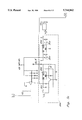
- FIGS. 5a-5h is a detailed electrical schematic diagram of the preferred embodiment of the instant invention.
- FIG. 6 is a flow chart of the software algorithm of the preferred embodiment of the instant invention illustrating the flow of basic algorithm steps used in conducting tests on battery cells.
- FIGS. 2-6 depict the preferred embodiments of the battery tester system 10 which generally comprises a data storing battery multimeter 10 for measuring, recording and displaying readings of internal cell voltage, internal cell resistance and intercell connection resistance. Other data specific to each battery being tested may be manually entered and stored in the battery tester 10, such as specific gravity and temperature.
- the instant invention is an automated microprocessor or microcontroller operated testing and display unit for processing and displaying the foregoing measurements.
- the instant invention is preferably computer compatible whereby it may be electricallylinked to a personal computer 230 or network for downloading or extracting data recordings from the tester obtained by the tester 10 during testing for further analysis and report generation.
- the battery tester 10 may be used for automatically testing a single cell 5 or multicell battery sourcemodule. Large industrial type backup DC battery sources typically include aplurality of battery cells 5 electrically connected in series by intercell connectors.
- the preferred embodiment of the instant invention is a self contained, battery powered unit 10 comprising a microcontroller 130 or microprocessorwith internal or external RAM, ROM and a timer, load resistance circuit 20,a display 110 and rechargeable battery 210.
- the tester 10 of the invention measures float voltages, internal cell resistance, intercell resistance and load voltages for at least one battery cell 5.
- Float voltage is a measurement of battery voltage during full float operation wherein no loadis applied and the cell is charged.
- the internal cell resistance test determines the internal resistance of a battery cell 5 by how that cell responds to a momentary load 20-26. The instantaneous voltage drop across the cell and load current are measured and used by the battery tester 10 to calculate the cell's internal resistance.
- the battery tester 10 provides microprocessing hardware and software algorithms, such as that shown in FIG. 6, which make the measurements possible on battery cells that are floating and that have loads while they remain on line. That is, unlike the background systems, the battery tester 10 performs DC load testing while a battery cell or modular of cells are in service and while the battery charger remains electrically connected and powered.
- Intercell resistance is a measurement of the total electrical resistance of the connection 7 electrically linking two battery cells. This connection is usually a conductive link 7 from the positive post of the cell being tested to the positive post of the electrically linked or next cell. The intercell resistance test checks for bad connections.
- the battery tester 10 may provide two sets of test leads, or two sets of test leads connectable to the tester may be used with the instant invention for making the foregoing measurements.
- One set, or the first set is a standard set of digital voltmeter probes, while the second set 14 comprises a three clip set used in the multimeter mode of the battery tester, as seen in FIG. 2.
- the three clip set comprises two dual conductortest clips 14a, 14c and a third single conductor clip 14b. In the two dual conductor test clips a conductive element is situated in each leg of each clip so two conductive paths are provided.
- One path in each of the two clips allows a lead to be connected between the positive terminal of two battery cells via inputs 56 and 58, while the second path allows voltage measurements and/or current measurements to be made via inputs 50 and 54.
- the two dual connector test clips are used for connecting across the cell 5 being tested and its associated intercell connector 7 making the electrical link from the positive post of the cell being tested to the positive post of the adjacent cell.
- the third single conductor clip defined by the second set is used for connecting to the negative terminal of the cell being tested for measuring voltage drop and/or voltage across the cell being tested and the intercell connector via input 52. From theseconnections the instant invention may be utilized for making the foregoing measurements. Once connected, the user initiates the test sequence.
- the battery tester 10 measures and records the cell float voltage before the load is applied.
- the battery tester 10 applies or connects a fixed resistance load 21, 26, and 22 or 24 across the cell being tested and the intercell being tested, forcing a current of approximately 70 amperes from the battery to flow for a few seconds through the load.
- a 2 volt, 6 volt or 12 volt load is applied.
- These leads are selected by triggering automatically either relay 21a, 24a or 26a, respectively.
- the battery tester 10 reads the current and voltage drawn which is necessary to calculate the intercell connection resistance and the internal cell resistance.
- the user may connect the battery tester 10 via a serial port 180, such as RS-232, into a standard PC compatible computer and initiate the software algorithms of the instant invention.
- the software imported is menu driven for extracting data and making analysis and report profiles as supplied by the instant invention.
- Once data is extracted from the battery tester 10 the information may be displayed in an easy to read format on the accompanying computer 230 being used.
- the user may merely use the battery tester 10 as defined to generate a report and analysis and use its display 110.
- a user may download the software defined by the instant invention into the PC for operating the instant invention.
- the battery tester 10 be used for conducting the load and no load voltage measurements and the resistance calculations once the connections are made and then subsequently transferring the data stored inthe tester 10 to the serial port linked computer.
- the battery tester 10 provides the hardware and software algorithms for conducting the above-noted measurements. Therefore, the instant invention comprises ROM 140-150, RAM 160-170 and microprocessing hardware.
- the instant invention comprises a resistance loadingdevice 21-26, load module driver circuit 80, a parallel input/output controller (PIO) 92 and circuit 90, a microcontroller 130, program ROM 140, upload program ROM 150, program RAM 160 which may include a temporarymemory RAM, data storage RAM 170, address decoder circuit 120 for interfacing and communicating with the noted ROMs, RAMs, microcontroller 130, and PIO 92, an input divider circuit 40 and pre-AMP circuit 30, a multiplexer (MUX) 60, and an A/D converter circuit 70 system.
- PIO parallel input/output controller
- the instant invention may also include a display 110, keyboard 101 and a keyboard decoder 100 which interfaces with the PIO 92.
- the invention includes a backup power supply 200, including a battery 200 and battery charger 210.
- the essential elements of the instant invention arethe microcontroller 130, at least one ROM 150, at least one RAM 160, a PIO controller 92, an A/D converter 70, and an adjustable resistance load circuit 20 which may be interchangeably applied for different load levels.
- FIG. 2 a simple diagram illustrates the complete unit ofthe instant invention 10 connected or linked by the three clip set or second set 14 to a cell 5 being tested, the intercell connectors, and the corresponding adjacent cell 6.
- the second set one clip 14a is connected to the positive post 5a of the cell being tested, the second clip 14b is connected to the negative post of the cell being tested, and the third clip 14c connected to the positive post of the corresponding cell 6.
- These connections allow the battery test instrument 10 to test and read float voltage, cell load voltage, current draw, intercell voltage drop, and intercell and internal cell resistance as calculated from the voltage drop and current draws.
- the current draw is really the current drawn from the battery as caused by the load applied.
- FIG. 4 a more detailed block diagram of the hardware of the battery tester 10 is shown, illustrating the input divider circuit 40,pre-AMP circuit 30, multiplexer 60, resistance load circuit 20, load drivercircuit 80, PIO 92, analog to digital (A/D) converter 70, microcontroller 130, RAM 160-170, ROM 140-150, the display 110, the keyboard decoder 100, the keyboard 101, the RS-232 serial interface 180 and the power supply.
- the input divider circuit 40 shown in FIG. 3, is electrically coupled in shunt across the positive and negative terminals of the tested cell 5. This coupling shunt actually occurs between the tested cell V1 input 54 and the V2 input 52 which correspond to the positive terminal post and negative terminal post, respectively, of the tested cell 5.
- the input divider circuit takes the voltage input from the tested cell 5 and reducesit by voltage dividing circuitry to a level below a predetermined threshold, e.g. for volts, so that it may be received, read and processed by the A/D converter.
- the input divider circuit 40 receives voltage inputsfrom cell 5 and reduces them to the preferred DC voltage.
- the input dividercircuit 40 is designed to receive up to 16 volts and reduces inputs to a maximum voltage of 4 volts. These levels have been selected since most batteries used today do not exceed 16 volts as higher voltage requirementsare obtained by connecting battery cells in series. Therefore, the input divider circuit 40 may be designed for receiving higher direct current voltage inputs without departing from the scope and spirit of the instant invention.
- the pre-amp circuit 30 comprises an amplifier circuit electrically shunted across the intercell conductor link 7 for receiving, amplifying and measuring the voltage drop across the intercell conductor 7. As shown in the figure, the pre-amp 30 is connected to the V2 input 52 and the V3 input 50 which correspond to the negative terminal post of the tested cell 5 and the positive terminal post of the series connected cell 6, respectively. The pre-amp circuit 30 simply amplifies the DC voltage drop input received from the drop across the intercell since the drop is normally low and requires amplification for accurate processing.
- the multiplexer circuit 60 comprises a conventional MUX integrated circuit chip which selects inputs in a predetermined order dictated by the system's software and PIO controller for routing to the A/D converter.
- TheMUX 60 includes a plurality of solid state relays, or similar relays, whichare sequentially triggered as determined by the software and PIO controllerand outputted to the A/D converter.
- the outputs from the pre-amp circuit 30and the input divider circuit 40 are fed into the MUX 60.
- the current sense lines from the positive and negative load inputs 58, 56 respectively, as shown connected to the load resistor 26, are also fed into the MUX 60.
- the A/D converter circuit 70 merely converts analog inputs to digital outputs for processing by the rest of the circuit components such as the PIO controller 92, address decoder 120, the microcontroller 130 and the ROM and RAM storage locations 140-170.
- the A/Dconverter circuit 70 includes an A/D reference circuit 74 and an A/D clock 76.
- the A/D converter circuit 70 comprises a conventional analog to digital converting circuit which utilizes A/D reference inputs and A/D clocking for referencing analog to digital conversion and timing.
- the load circuit 20 provides a series of resistive loads including preferably 2 volts, 6 volt and 12 volt loads for placement across the V1 and V3 terminal post, i.e. the positive terminal post on the tested cell 5and the positive terminal post on the series connected cell 6, via positiveand negative load inputs 58 and 56, respectively. These loads are placed across the positive terminal post of the series cells for drawing current and taking current sense measurements via current sense lines 28 and 29 electrically tapping to load resistor 26 as shown in FIG. 3. These loads may be user selected from the keyboard or keypad 101 or automatically selected via the software and PIO controller 92.
- the loads in the loading circuit 20 include a 2 volt relay 21a, a 6 volt relay 24a and a 12 volt relay 26a which are electrically coupled to and responsive to the load driver circuit 80.
- the load driver circuit 80 controls these relays 21a, 24a, and 26a while the load driver circuit 80 is controlled by outputs from the PIO controller 92. That is, the load driver circuit 80 and the PIO controller 92 are electrically interfaced as are the load driver circuit and the resistive load circuit 20.
- the PIO controller 92 is also electrically coupled to the multiplexer's circuit 60, for controlling the same.
- the PIO controller 92 further receives outputs from the keyboard decoder 100 which receives its inputs from the keyboard or keypad 101.
- the PIO controller 92 is also electrically interfaced with the microcontroller 130, the A/D converter circuit 70 and the address decoder circuit 120 via 16 byte and 8 byte address bus and data bus links, respectively, 220, 222, for transferring control and data signals.
- the PIO controller 92 is a programmed input and output controller for controlling inputs and outputs from the A/D converter 72, the keyboard decoder 100, the multiplexer 60, the load driver circuit 80 and the ROM and RAM locations 140-170.
- the PIO controller 92 may be a conventional program input and output integrated circuit chip.
- the PIO controller 92 may be further defined as a parallel input/output integrated circuit which provides additional input and outputlines for transmitting non-communication busses capable of handling 8 byte to 32 byte words such as those from the load driver circuit 80 which turnson select relays.
- the keyboard decoder 100 is electrically interfaced, preferably by a multilink cable or bus to the keyboard or keypad 101 for receiving and decoding input from the keyboard 101 for running tests as dictated by the user.
- the keyboard or keypad is accessible by any user from the outside ofthe unit enclosure casing as shown in FIG. 2.
- the keyboard decoder producesoutputs which electrically interface with the PIO controller 92.
- the keyboard decoder outputs are electrically connected to the microcontroller at select pin connections on the keyboard decoder integrated circuit chip and the microcontroller for processing user interface inputs.
- the microcontroller 130 of the instant invention as shown in FIGS. 3 and 4electrically interfaces and controls signal and data processing to the program ROM 140, the upload program ROM 150, the program RAM 160, the datastorage RAM 170, the address decoder 120, the display 110, the A/D converter 72 and the PIO controller 92 based on selected inputs from the keyboard decoder 100, the PIO controller 92, the address decoder 120, the information serial port 180 and other inputs as shown in the detailed circuit diagram of FIG. 5.
- the microcontroller may be described as a microprocessor having internal RAM, ROM and timer circuitry which in most conventional microprocessors is outside the integrated chip.
- the microcontroller 130 interfaces with the program and data ROM and RAM locations as shown. In the alternative, aconventional microprocessor may be utilized for accomplishing the same results.
- the microcontroller 130 also interfaces with an address latch integrated circuit 125 which is comprised in the address decoder 120 shownin FIG. 3 and FIG. 4. Referring to FIG. 5, the address latch is shown electrically interfaced to the microcontroller 130, the address decoder 120 and the PIO controller 92 for addressing control and data signals between these circuits and the ROM program memory 140, the upload program ROM 150, the program RAM 160 having temporary scratch pad memory and the data storage RAM 170.
- the address latch circuit 125 may interface with themicrocontroller 130 via a 16 byte address bus.
- the first 8 bytes of the address bus are also data bus latches while the other 8 bytes are for the address and are tied to the address bus. That is, that total bus size from the microcontroller 130 is 16 bytes which uses the 16 bytes as an address bus while the first 8 bytes comprise a databus latching medium.
- the address decoder 120 decodes the target address based on user and hardware input thereby identifying and controlling the communications with the microcontroller 130.
- the decoder 120 determines which peripheral, such as a RAM, ROM, PIO, serial port or display, the microcontroller 130 wants to talk to and decides which peripheral communicates with the microcontroller130 at a given time. Accordingly, the decoder 120 interfaces with the RAM and ROM locations, 140-170, and the display 110, as well as the microcontroller 130.
- the decoder also has some electrical interconnection with the A/D converter 72 and the PIO controller 92.
- An interface serial port 180 is also shown in FIGS. 3 and 4 for communicating with computer peripherals.
- the interface serial port is preferably an RS-232 serial port interface but may be any other conventional communication link for communicating with the microcontrollerwithout departing from the scope and spirit of the instant invention.
- the serial port interface allows obtained data measurements and calculations to be downloaded along with a menu driven program into a peripheral computer so that battery cell data may be further analyzed for determiningbattery cell integrity.
- a list of menu options may also be downloaded to a computer over the serial port so that the user may easily manipulate data inputs from the battery tester 10 or extract other information from the battery tester 10 and exercise various optional subroutines for extractingand analyzing data procured from the battery tester.
- the instant invention is preferably powered from a conventional wall outletsupplying 110 to 120 VAC.
- the instant invention supplies a backup rechargeable battery 205 source for providing backup power to the battery tester unit 10 in the event of main VAC power failure.
- a power supply charger 210 is supplied, as shown in FIGS. 3 and 4, for charging the backup battery 205.
- the power supply in FIG. 4 is shown by the reference numeral 200 which includes the main and backup power.
- FIG. 3 another block diagram of the instant invention isshown, a simplified block diagram illustrating the electrical links and communication between the display 110, keyboard 101 and keyboard decoder 100, PIO controller 92, address decoder 120, the resistance load circuit 20 including resistance loads 21-26, load module driver circuit 80, input divider circuit 40, pre-AMP circuit 30, multiplexer 60, A/D converter circuit 70, microcontroller 130, and the ROM 140-150 and RAM 160-170.
- the ROM includes program ROM 140 and upload program ROM 150
- RAM includes programmed RAM and temporary memory RAM 160, data storage RAM 170.
- FIG. 3 the detailed breakdown of ROM and RAM are not shown whereinthey are merely shown as ROM and RAM memory but nonetheless accomplish the same results as discussed with reference to FIG. 4.
- serial port 180 and the power supply 200 which includes conventional 110-120 VAC wall outlet power and a power supply charger 210 for charging a backup battery 205.
- the address decoder 120 which includesthe address latch 125 and decoder 126, the PIO controller output 92, the A/D converter 72, and the display 110 are typically conducted over 8 and 16 byte address buses 222 and 220 respectively, as previously discussed.
- the routing and controlling of measurements from the current sense lines 28, 29 and voltage drop readings between 50, 52 and 54 are dictated by theMUX 60 which receives current sense and voltage drop analog inputs and outputs those to the A/D converter.
- the MUX 60 thereby selects inputs to the A/D converter 72 for reading.
- the inputs selected include the intercell voltage drop, the battery cell voltage drop and the current loadas internally measured.
- the A/D converter 72 converts the analog signals todigital for routing to the microcontroller 130 and the ROM and RAM locations 140-170.
- FIGS. 5a-5h a more detailed schematic diagram of the instant invention hardware is shown.
- the various circuits and their interface and interaction as noted above is shown in detailed schematic view in FIG. 5.
- the address latch 125 and decoder 126 comprising the address decoder 120,are shown interfacing over 8 byte and 16 byte buses with the PIO controller92, the ROM program memory 140, the ROM software update 150, the program RAM or temporary scratch pad memory 160 and the data storage RAM 170 and the microcontroller 130.
- the exact PIN locations are not identified but the electrical communication is clear.
- Voltage inputs from the tested cell5 and the series connected cell are received by the input jack J4 and voltage divided by the input divider circuit 40 which includes relays 42, 44, and 46.
- the intercell conductor voltage drop across V2 and V3, i.e. 52and 50, are amplified in the pre-amp circuit 30 which includes amplifier 32, and variable amplification resistor 33, relay 34, a varister 38 and signal conditioning resistive loads 36 for dictating the level of amplification.
- the load driver circuit 80 controls the 2 volt, 6 volt and 12 volt relays 21a, 24a, and 26a, respectively, via the PIO, transistors 82, 84 and 86 and their corresponding resistive loads.
- the transistor 88 shown in the load driver circuit 80 is connected to an 8 volt battery supply as shown, while the transistor 89 is electrically coupled to a fan control also shown.
- the keyboard decoder integrated circuit 100 electrically interfaces with the keyboard and keypad 101 and supplies outputs to the PIO controller 92 and microcontroller 130.
- the PIO controller 92 is selectably interfaced with the load driver circuit 40 as shown for automatically selecting the appropriate loads for the tests being conducted by the user as dictated through the user interface 101.
- the PIO controller 92 communicates with the A/D converter 72 ROM and RAM memory locations 140-170, the microcontroller 130 and the decoder 126 as shown.
- the PIO controller 92 primarily communicates over an 8 byte bus with the address latch 125 and the ROM and RAM locations 140-170, and the microcontroller 130 as shown.
- the microcontroller 130 establishes a communication link with the serial port 180 as shown, wherein the serial port incorporated is an RS-232 as shown.
- the RS-232 serial port 180 is coupled to a multi-pin jack J1 as shown.
- An optional audible buzzer 131 may be connected to the microcontroller 130 for sounding an audible alarm when positive connections are made with the tested cell 5.
- the buzzer is referenced by numeral 131.
- the A/D clock used for controlling the timing of the A/D converter 72, as shown by reference numeral 76, is preferably a counter divided by sixty for clocking down.
- the A/D clock comprises NOR gates 76a and 76b, a crystal oscillator 76e connected to integrated chip 76f which feeds outputs to NOR gate 76b, and flip flops 76c and 76d which provide outputs to the A/D converter 72 as shown.
- the A/D reference 74 provides reference voltages to the A/D converter 72 and comprises an integrated chip 74a and a reference adjustment resistive load 74b, as shown.
- the power supply 200 is also shown in FIG. 5 and includes a fuse 201, preferably rated for 1 to 2 amperes, and voltage controller chips 202 and 203. Grounding capacitors are also shown for filtering out noise and they are referenced by numeral 204 collectively.
- the foregoing generally outlines the schematic of FIG. 5, but more detailed analysis may be made and referenced to the schematic as shown.
- FIG. 6 A flow chart of the instant invention is shown in FIG. 6, illustrating the main and basic steps conducted.
- This software algorithm of the instant invention communicates and connects conventional hardware components in a unique manner to provide automatic testing of battery cells in a way undisclosed by background devices.
- the flow chart of FIG. 6 is referenced by numeral 300 where it begins at the starting point 310.
- the battery cellto be tested 5 is first connected with the second set three clip probe, as previously discussed. After the connections are made to the battery cell being tested 5 and the series connected cell, as shown in FIGS. 3-5, the software of the instant invention reads and stores float voltages, that isthe battery cell voltages before a load is applied. See block 312.
- the instant invention applies a resistive load or loads to the tested cell 5 via the load driver circuit 40.
- the instant invention preferably verifies proper and safe connections and conditions by reading the current draw to verify whether it is within proper limits. If this test fails then the testing isterminated as indicated by block 318. If the current readings are within the predetermined limits then the test proceeds as shown by decision block316.
- a load preferably remains electrically coupled to the tested cell and intercell connect 7 for a minimum of 4 seconds thereby allowing for natural voltage drop in the battery which occurs instantaneously as discussed and noted above.
- Block 320 After this predetermined time lapse as shown byblock 320, the instant invention subroutines cause the current draw and intercell voltage to be read or measured for calculating the intercell resistance.
- Block 322 further shows that after reading the intercell current and voltage drop, calculations are made by the algorithm to determine intercell resistance which is subsequently stored in the data storage RAM location 170.
- the intercell resistance is a resistance measurement and calculation of the intercell connect 7 joining the tested cell and series cell in an electrical series and is thereby a calculation of the intercell connect voltage drop divided by its current draw.
- the current sense lines 28 and 29 allow for the reading of currents.
- the internal cell resistance is next determined for the cell being tested 5by reading the internal cell voltage underload and the current draw.
- the instant invention provides an automated way of applying and removing loads and performing integrity tests on battery cells for determining a battery cell's capacity.
- the tests performed are controlled by software which performs DC load testing in an automated way and stores the results in RAM and temporary RAM memory locations for performing calculations and extracting the data obtained.
- the data extractions may be imported to a network or computer peripheral over the serial ports, as shown and discussed with reference to the figures.
- the instant invention also supplies a first set of probes for conducting conventional voltmeter and multimeter readings apart from the automated test as just discussed.
Abstract
Description
Claims (15)
Priority Applications (1)
| Application Number | Priority Date | Filing Date | Title |
|---|---|---|---|
| US08/404,031 US5744962A (en) | 1995-03-14 | 1995-03-14 | Automated data storing battery tester and multimeter |
Applications Claiming Priority (1)
| Application Number | Priority Date | Filing Date | Title |
|---|---|---|---|
| US08/404,031 US5744962A (en) | 1995-03-14 | 1995-03-14 | Automated data storing battery tester and multimeter |
Publications (1)
| Publication Number | Publication Date |
|---|---|
| US5744962A true US5744962A (en) | 1998-04-28 |
Family
ID=23597855
Family Applications (1)
| Application Number | Title | Priority Date | Filing Date |
|---|---|---|---|
| US08/404,031 Expired - Lifetime US5744962A (en) | 1995-03-14 | 1995-03-14 | Automated data storing battery tester and multimeter |
Country Status (1)
| Country | Link |
|---|---|
| US (1) | US5744962A (en) |
Cited By (112)
| Publication number | Priority date | Publication date | Assignee | Title |
|---|---|---|---|---|
| US5909583A (en) * | 1997-01-17 | 1999-06-01 | Dell Usa, L.P. | Method for making redundant power supplies hot-pluggable |
| US6037778A (en) * | 1997-11-05 | 2000-03-14 | Stat Engineering Company, L.L.C. | Electronic battery testing device and method for testing batteries |
| US6041008A (en) * | 1998-05-13 | 2000-03-21 | Micron Technology Inc. | Method and apparatus for embedded read only memory in static random access memory |
| US6061638A (en) * | 1997-07-30 | 2000-05-09 | Auto Meter Products, Inc. | Microprocessor-based battery tester system |
| EP1085592A2 (en) * | 1999-09-17 | 2001-03-21 | Matsushita Electric Industrial Co., Ltd. | Method for detecting abnormal battery cell |
| US6254438B1 (en) | 1999-10-21 | 2001-07-03 | Snap-On Tools Company | Battery side-terminal adapter and Kelvin connector |
| US6424157B1 (en) * | 1998-07-20 | 2002-07-23 | Alliedsignal, Inc. | System and method for monitoring a vehicle battery |
| US6507196B2 (en) * | 1998-06-24 | 2003-01-14 | Intra International Ab | Battery having discharge state indication |
| US20030155930A1 (en) * | 2000-04-25 | 2003-08-21 | Jes Thomsen | Current measuring circuit suited for batteries |
| US6624635B1 (en) * | 1999-10-23 | 2003-09-23 | Cisco Technology, Inc. | Uninterruptable power supply |
| US20030185084A1 (en) * | 2002-03-29 | 2003-10-02 | Alps Electric Co., Ltd. | Integrated circuit capable of easily applying address selection voltage |
| US20030197512A1 (en) * | 2002-04-22 | 2003-10-23 | Michael Miller | Battery analyzer |
| US6664792B1 (en) * | 1998-09-29 | 2003-12-16 | Intel Corporation | Method and apparatus for battery power pre-check at system power-on |
| US6677759B2 (en) | 2001-05-02 | 2004-01-13 | Microchip Technology Incorporated | Method and apparatus for high-voltage battery array monitoring sensors network |
| US20040036475A1 (en) * | 2000-09-04 | 2004-02-26 | Pascoe Phillip Enwood | Battery monitoring |
| FR2846149A1 (en) * | 2002-10-16 | 2004-04-23 | Renault Sa | DEVICE FOR DIAGNOSING THE CORROSION STATE OF A BATTERY, PARTICULARLY A MOTOR VEHICLE |
| US20040113494A1 (en) * | 2000-09-01 | 2004-06-17 | Karuppana Samy V. | Daytime running light control using an intelligent power management system |
| US20040207367A1 (en) * | 2003-04-15 | 2004-10-21 | Denso Corporation | Internal condition detection system for a charge accumulating device |
| US20050208368A1 (en) * | 1998-08-10 | 2005-09-22 | Toyota Jidosha Kabushiki Kaisha | Method and device for judging the condition of secondary batteries and method for regenerating secondary batteries |
| US20050206388A1 (en) * | 2003-12-30 | 2005-09-22 | Quint Jonathan B | Battery management system and apparatus with anomaly reporting |
| US6992487B1 (en) | 2003-05-29 | 2006-01-31 | La Marche Manufacturing Co. | Arrangement for testing battery while under load and charging |
| US20060043975A1 (en) * | 2004-08-31 | 2006-03-02 | Eaglepicher Technologies, Llc | System and method for nondestructive testing of thermal batteries |
| US20060259256A1 (en) * | 2001-11-01 | 2006-11-16 | Linear Technology Corporation | Circuits and methods for current measurements referred to a precision impedance |
| US20070069734A1 (en) * | 1997-11-03 | 2007-03-29 | Bertness Kevin I | Automotive vehicle electrical system diagnostic device |
| US7505856B2 (en) * | 1999-04-08 | 2009-03-17 | Midtronics, Inc. | Battery test module |
| US7557586B1 (en) * | 1999-11-01 | 2009-07-07 | Midtronics, Inc. | Electronic battery tester |
| US20090224771A1 (en) * | 2008-03-05 | 2009-09-10 | Liebert Corporation | System and method for measuring battery internal resistance |
| US20090281928A1 (en) * | 2003-12-30 | 2009-11-12 | Quint Jonathan B | Battery management system with runtime reserve analysis |
| US20090313347A1 (en) * | 2008-06-16 | 2009-12-17 | Agilent Technologies, Inc. | System and Method to Integrate Measurement Information within an Electronic Laboratory Notebook Environment |
| US7642787B2 (en) * | 1997-11-03 | 2010-01-05 | Midtronics Inc. | Automotive vehicle electrical system diagnostic device |
| US7688074B2 (en) | 1997-11-03 | 2010-03-30 | Midtronics, Inc. | Energy management system for automotive vehicle |
| US7706991B2 (en) | 1996-07-29 | 2010-04-27 | Midtronics, Inc. | Alternator tester |
| US7710119B2 (en) | 2004-12-09 | 2010-05-04 | Midtronics, Inc. | Battery tester that calculates its own reference values |
| US7728597B2 (en) | 2000-03-27 | 2010-06-01 | Midtronics, Inc. | Electronic battery tester with databus |
| US7772850B2 (en) | 2004-07-12 | 2010-08-10 | Midtronics, Inc. | Wireless battery tester with information encryption means |
| US7774151B2 (en) | 1997-11-03 | 2010-08-10 | Midtronics, Inc. | Wireless battery monitor |
| US7777612B2 (en) | 2004-04-13 | 2010-08-17 | Midtronics, Inc. | Theft prevention device for automotive vehicle service centers |
| US7791348B2 (en) | 2007-02-27 | 2010-09-07 | Midtronics, Inc. | Battery tester with promotion feature to promote use of the battery tester by providing the user with codes having redeemable value |
| EP2226642A1 (en) | 2009-03-05 | 2010-09-08 | SafeLine Europe | A method and a device for verifying the capacity of an emergency battery |
| US7808375B2 (en) | 2007-04-16 | 2010-10-05 | Midtronics, Inc. | Battery run down indicator |
| WO2011072939A1 (en) * | 2009-12-18 | 2011-06-23 | Sb Limotive Company Ltd. | Method for determining contact and connector resistances in a battery pack and battery system for determining contact and connector resistances in a battery pack |
| US20110159327A1 (en) * | 2009-12-28 | 2011-06-30 | Bobby Hardwick | Reusable electrochemical cell test fixture |
| US7977914B2 (en) | 2003-10-08 | 2011-07-12 | Midtronics, Inc. | Battery maintenance tool with probe light |
| US7999505B2 (en) | 1997-11-03 | 2011-08-16 | Midtronics, Inc. | In-vehicle battery monitor |
| US20110257913A1 (en) * | 1996-07-29 | 2011-10-20 | Philbrook John S | Electronic battery tester with battery age input |
| WO2011143532A1 (en) * | 2010-05-14 | 2011-11-17 | Liebert Corporation | Float current monitor |
| WO2011143535A1 (en) * | 2010-05-14 | 2011-11-17 | Liebert Corporation | Battery monitor with correction for internal ohmic measurements of battery cells in parallel connected battery strings |
| US8120363B2 (en) | 2008-11-24 | 2012-02-21 | Cummins Power Generation Ip, Inc. | Voltage drop compensation for an electric power storage device charging system |
| US8164343B2 (en) | 2003-09-05 | 2012-04-24 | Midtronics, Inc. | Method and apparatus for measuring a parameter of a vehicle electrical system |
| US8198900B2 (en) | 1996-07-29 | 2012-06-12 | Midtronics, Inc. | Automotive battery charging system tester |
| US8203345B2 (en) | 2007-12-06 | 2012-06-19 | Midtronics, Inc. | Storage battery and battery tester |
| US8237448B2 (en) | 2000-03-27 | 2012-08-07 | Midtronics, Inc. | Battery testers with secondary functionality |
| CN102652267A (en) * | 2009-12-11 | 2012-08-29 | 罗伯特·博世有限公司 | Determining the internal resistance of a battery cell of a traction battery that is connected to a controllable motor/generator |
| US8306690B2 (en) | 2007-07-17 | 2012-11-06 | Midtronics, Inc. | Battery tester for electric vehicle |
| US8344685B2 (en) | 2004-08-20 | 2013-01-01 | Midtronics, Inc. | System for automatically gathering battery information |
| US8436619B2 (en) | 2004-08-20 | 2013-05-07 | Midtronics, Inc. | Integrated tag reader and environment sensor |
| US8442877B2 (en) | 2004-08-20 | 2013-05-14 | Midtronics, Inc. | Simplification of inventory management |
| US20130181513A1 (en) * | 2010-09-30 | 2013-07-18 | Junya Yano | Power supply device and vehicle using the same |
| US8513949B2 (en) | 2000-03-27 | 2013-08-20 | Midtronics, Inc. | Electronic battery tester or charger with databus connection |
| US8674711B2 (en) | 2003-09-05 | 2014-03-18 | Midtronics, Inc. | Method and apparatus for measuring a parameter of a vehicle electrical system |
| US8738309B2 (en) | 2010-09-30 | 2014-05-27 | Midtronics, Inc. | Battery pack maintenance for electric vehicles |
| CN104335059A (en) * | 2012-06-08 | 2015-02-04 | 罗伯特·博世有限公司 | Method and device for determining internal resistance of battery cells of battery |
| US8958998B2 (en) | 1997-11-03 | 2015-02-17 | Midtronics, Inc. | Electronic battery tester with network communication |
| EP2840401A1 (en) * | 2013-08-12 | 2015-02-25 | GS Yuasa International Ltd. | Electric Storage- and controldevice, system and method |
| US9018958B2 (en) | 2003-09-05 | 2015-04-28 | Midtronics, Inc. | Method and apparatus for measuring a parameter of a vehicle electrical system |
| DE102014200343A1 (en) * | 2014-01-10 | 2015-07-16 | Robert Bosch Gmbh | A method of determining increased resistance of a cell connector |
| US20150204995A1 (en) * | 2013-07-29 | 2015-07-23 | SeeScan, Inc. | Inductive clamp devices, systems, and methods |
| US20150219727A1 (en) * | 2014-02-06 | 2015-08-06 | Global Energy Innovations, Inc. | Battery Monitoring System Including Relay Test Circuit |
| US9201120B2 (en) | 2010-08-12 | 2015-12-01 | Midtronics, Inc. | Electronic battery tester for testing storage battery |
| DE102015008066A1 (en) | 2014-06-25 | 2015-12-31 | Battery Technology Holdings, Llc | Test device for a device, device or component with distributed processing function |
| US9229062B2 (en) | 2010-05-27 | 2016-01-05 | Midtronics, Inc. | Electronic storage battery diagnostic system |
| US9244100B2 (en) | 2013-03-15 | 2016-01-26 | Midtronics, Inc. | Current clamp with jaw closure detection |
| US9255955B2 (en) | 2003-09-05 | 2016-02-09 | Midtronics, Inc. | Method and apparatus for measuring a parameter of a vehicle electrical system |
| US9274157B2 (en) | 2007-07-17 | 2016-03-01 | Midtronics, Inc. | Battery tester for electric vehicle |
| US9312575B2 (en) | 2013-05-16 | 2016-04-12 | Midtronics, Inc. | Battery testing system and method |
| US20160170064A1 (en) * | 2014-12-11 | 2016-06-16 | Joseph Romeo | Method and device for non-invasively determining the use of non-electrically conductive plumbing in a residence |
| CN105738833A (en) * | 2016-05-12 | 2016-07-06 | 上海奉天电子股份有限公司 | Automobile battery health condition diagnosis method and diagnostic apparatus |
| DE102015201920A1 (en) * | 2015-02-04 | 2016-08-04 | Bayerische Motoren Werke Aktiengesellschaft | Method for measuring a contact resistance |
| US9419311B2 (en) | 2010-06-18 | 2016-08-16 | Midtronics, Inc. | Battery maintenance device with thermal buffer |
| US9425487B2 (en) | 2010-03-03 | 2016-08-23 | Midtronics, Inc. | Monitor for front terminal batteries |
| US9466995B2 (en) | 2013-11-07 | 2016-10-11 | Stored Energy Systems, a Limited Liability Company | Self-contained automatic battery charging systems and methods |
| US9496720B2 (en) | 2004-08-20 | 2016-11-15 | Midtronics, Inc. | System for automatically gathering battery information |
| US9588185B2 (en) | 2010-02-25 | 2017-03-07 | Keith S. Champlin | Method and apparatus for detecting cell deterioration in an electrochemical cell or battery |
| US9619612B2 (en) | 2012-10-15 | 2017-04-11 | Battery Technology Holdings, Llc | Tester for equipment, apparatus, or component with distributed processing function |
| US9851411B2 (en) | 2012-06-28 | 2017-12-26 | Keith S. Champlin | Suppressing HF cable oscillations during dynamic measurements of cells and batteries |
| US9857430B2 (en) | 2012-10-15 | 2018-01-02 | Battery Technology Holdings, Llc | Tester for equipment, apparatus or component with distributed processing function |
| US9923289B2 (en) | 2014-01-16 | 2018-03-20 | Midtronics, Inc. | Battery clamp with endoskeleton design |
| US9948125B2 (en) | 2013-11-07 | 2018-04-17 | Stored Energy Systems, a Limited Liability Company | Systems and methods for self-contained automatic battery charging and battery-life-extension charging |
| US9966676B2 (en) | 2015-09-28 | 2018-05-08 | Midtronics, Inc. | Kelvin connector adapter for storage battery |
| US10046649B2 (en) | 2012-06-28 | 2018-08-14 | Midtronics, Inc. | Hybrid and electric vehicle battery pack maintenance device |
| CN109416391A (en) * | 2016-07-12 | 2019-03-01 | 宝马股份公司 | For determining method, battery module and the device of the internal resistance of battery cell |
| US10222397B2 (en) | 2014-09-26 | 2019-03-05 | Midtronics, Inc. | Cable connector for electronic battery tester |
| US10302707B2 (en) | 2010-06-03 | 2019-05-28 | C & C Power, Inc. | Battery system and management method |
| US10317468B2 (en) | 2015-01-26 | 2019-06-11 | Midtronics, Inc. | Alternator tester |
| US10429449B2 (en) | 2011-11-10 | 2019-10-01 | Midtronics, Inc. | Battery pack tester |
| US10473555B2 (en) | 2014-07-14 | 2019-11-12 | Midtronics, Inc. | Automotive maintenance system |
| US10608353B2 (en) | 2016-06-28 | 2020-03-31 | Midtronics, Inc. | Battery clamp |
| US10677818B1 (en) * | 2017-06-19 | 2020-06-09 | Cardell Damian Webster | Dual circuit current loading analysis apparatus |
| US10843574B2 (en) | 2013-12-12 | 2020-11-24 | Midtronics, Inc. | Calibration and programming of in-vehicle battery sensors |
| US11054480B2 (en) | 2016-10-25 | 2021-07-06 | Midtronics, Inc. | Electrical load for electronic battery tester and electronic battery tester including such electrical load |
| US11215669B2 (en) * | 2017-12-14 | 2022-01-04 | Lg Chem, Ltd. | Apparatus and method for measuring voltage |
| US11325479B2 (en) | 2012-06-28 | 2022-05-10 | Midtronics, Inc. | Hybrid and electric vehicle battery maintenance device |
| DE102022108417A1 (en) | 2021-04-08 | 2022-10-13 | Battery Technology Holdings Llc | PROCEDURE FOR TESTING BATTERIES |
| US11474153B2 (en) | 2019-11-12 | 2022-10-18 | Midtronics, Inc. | Battery pack maintenance system |
| US11486930B2 (en) | 2020-01-23 | 2022-11-01 | Midtronics, Inc. | Electronic battery tester with battery clamp storage holsters |
| US11513160B2 (en) | 2018-11-29 | 2022-11-29 | Midtronics, Inc. | Vehicle battery maintenance device |
| US20220404424A1 (en) * | 2021-06-22 | 2022-12-22 | Austin N. Watts | Automotive Battery Draw Monitor |
| US11545839B2 (en) | 2019-11-05 | 2023-01-03 | Midtronics, Inc. | System for charging a series of connected batteries |
| US11566972B2 (en) | 2019-07-31 | 2023-01-31 | Midtronics, Inc. | Tire tread gauge using visual indicator |
| US11650259B2 (en) | 2010-06-03 | 2023-05-16 | Midtronics, Inc. | Battery pack maintenance for electric vehicle |
| US11668779B2 (en) | 2019-11-11 | 2023-06-06 | Midtronics, Inc. | Hybrid and electric vehicle battery pack maintenance device |
| US11740294B2 (en) | 2010-06-03 | 2023-08-29 | Midtronics, Inc. | High use battery pack maintenance |
Citations (11)
| Publication number | Priority date | Publication date | Assignee | Title |
|---|---|---|---|---|
| US4352067A (en) * | 1980-06-02 | 1982-09-28 | Dc Electronic Industries, Inc. | Battery analyzer |
| US4423379A (en) * | 1981-03-31 | 1983-12-27 | Sun Electric Corporation | Battery testing techniques |
| US4697134A (en) * | 1986-07-31 | 1987-09-29 | Commonwealth Edison Company | Apparatus and method for measuring battery condition |
| US4707795A (en) * | 1983-03-14 | 1987-11-17 | Alber Engineering, Inc. | Battery testing and monitoring system |
| US4799039A (en) * | 1985-01-30 | 1989-01-17 | Dual-Lite Manufacturing | Emergency lighting supervisory system |
| US4816768A (en) * | 1988-03-18 | 1989-03-28 | Champlin Keith S | Electronic battery testing device |
| US4876513A (en) * | 1988-12-05 | 1989-10-24 | Globe-Union Inc. | Dynamic state-of-charge indicator for a battery and method thereof |
| US5250904A (en) * | 1991-08-08 | 1993-10-05 | Advanced Power Technology Inc. | Device for predicting imminent failure of a stationary lead acid battery in a float mode |
| US5281919A (en) * | 1988-10-14 | 1994-01-25 | Alliedsignal Inc. | Automotive battery status monitor |
| US5321627A (en) * | 1992-03-11 | 1994-06-14 | Globe-Union, Inc. | Battery monitor and method for providing operating parameters |
| US5345163A (en) * | 1991-06-05 | 1994-09-06 | Battery Master Inc. | Battery monitoring system |
-
1995
- 1995-03-14 US US08/404,031 patent/US5744962A/en not_active Expired - Lifetime
Patent Citations (11)
| Publication number | Priority date | Publication date | Assignee | Title |
|---|---|---|---|---|
| US4352067A (en) * | 1980-06-02 | 1982-09-28 | Dc Electronic Industries, Inc. | Battery analyzer |
| US4423379A (en) * | 1981-03-31 | 1983-12-27 | Sun Electric Corporation | Battery testing techniques |
| US4707795A (en) * | 1983-03-14 | 1987-11-17 | Alber Engineering, Inc. | Battery testing and monitoring system |
| US4799039A (en) * | 1985-01-30 | 1989-01-17 | Dual-Lite Manufacturing | Emergency lighting supervisory system |
| US4697134A (en) * | 1986-07-31 | 1987-09-29 | Commonwealth Edison Company | Apparatus and method for measuring battery condition |
| US4816768A (en) * | 1988-03-18 | 1989-03-28 | Champlin Keith S | Electronic battery testing device |
| US5281919A (en) * | 1988-10-14 | 1994-01-25 | Alliedsignal Inc. | Automotive battery status monitor |
| US4876513A (en) * | 1988-12-05 | 1989-10-24 | Globe-Union Inc. | Dynamic state-of-charge indicator for a battery and method thereof |
| US5345163A (en) * | 1991-06-05 | 1994-09-06 | Battery Master Inc. | Battery monitoring system |
| US5250904A (en) * | 1991-08-08 | 1993-10-05 | Advanced Power Technology Inc. | Device for predicting imminent failure of a stationary lead acid battery in a float mode |
| US5321627A (en) * | 1992-03-11 | 1994-06-14 | Globe-Union, Inc. | Battery monitor and method for providing operating parameters |
Cited By (164)
| Publication number | Priority date | Publication date | Assignee | Title |
|---|---|---|---|---|
| US8198900B2 (en) | 1996-07-29 | 2012-06-12 | Midtronics, Inc. | Automotive battery charging system tester |
| US20110257913A1 (en) * | 1996-07-29 | 2011-10-20 | Philbrook John S | Electronic battery tester with battery age input |
| US7706991B2 (en) | 1996-07-29 | 2010-04-27 | Midtronics, Inc. | Alternator tester |
| US7656162B2 (en) | 1996-07-29 | 2010-02-02 | Midtronics Inc. | Electronic battery tester with vehicle type input |
| US7940052B2 (en) | 1996-07-29 | 2011-05-10 | Midtronics, Inc. | Electronic battery test based upon battery requirements |
| US8872517B2 (en) * | 1996-07-29 | 2014-10-28 | Midtronics, Inc. | Electronic battery tester with battery age input |
| US5909583A (en) * | 1997-01-17 | 1999-06-01 | Dell Usa, L.P. | Method for making redundant power supplies hot-pluggable |
| US6061638A (en) * | 1997-07-30 | 2000-05-09 | Auto Meter Products, Inc. | Microprocessor-based battery tester system |
| US8674654B2 (en) | 1997-11-03 | 2014-03-18 | Midtronics, Inc. | In-vehicle battery monitor |
| US7642787B2 (en) * | 1997-11-03 | 2010-01-05 | Midtronics Inc. | Automotive vehicle electrical system diagnostic device |
| US20070069734A1 (en) * | 1997-11-03 | 2007-03-29 | Bertness Kevin I | Automotive vehicle electrical system diagnostic device |
| US7705602B2 (en) | 1997-11-03 | 2010-04-27 | Midtronics, Inc. | Automotive vehicle electrical system diagnostic device |
| US7999505B2 (en) | 1997-11-03 | 2011-08-16 | Midtronics, Inc. | In-vehicle battery monitor |
| US7688074B2 (en) | 1997-11-03 | 2010-03-30 | Midtronics, Inc. | Energy management system for automotive vehicle |
| US8493022B2 (en) | 1997-11-03 | 2013-07-23 | Midtronics, Inc. | Automotive vehicle electrical system diagnostic device |
| US7774151B2 (en) | 1997-11-03 | 2010-08-10 | Midtronics, Inc. | Wireless battery monitor |
| US8958998B2 (en) | 1997-11-03 | 2015-02-17 | Midtronics, Inc. | Electronic battery tester with network communication |
| US6037778A (en) * | 1997-11-05 | 2000-03-14 | Stat Engineering Company, L.L.C. | Electronic battery testing device and method for testing batteries |
| US6041008A (en) * | 1998-05-13 | 2000-03-21 | Micron Technology Inc. | Method and apparatus for embedded read only memory in static random access memory |
| US6507196B2 (en) * | 1998-06-24 | 2003-01-14 | Intra International Ab | Battery having discharge state indication |
| US6424157B1 (en) * | 1998-07-20 | 2002-07-23 | Alliedsignal, Inc. | System and method for monitoring a vehicle battery |
| US20050206389A1 (en) * | 1998-08-10 | 2005-09-22 | Toyota Jidosha Kabushiki Kaisha | Method and device for judging the condition of secondary batteries and method for regenerating secondary batteries |
| US20050214633A1 (en) * | 1998-08-10 | 2005-09-29 | Toyota Jidosha Kabushiki Kaisha | Method and device for judging the condition of secondary batteries and method for regenerating secondary batteries |
| US20050208368A1 (en) * | 1998-08-10 | 2005-09-22 | Toyota Jidosha Kabushiki Kaisha | Method and device for judging the condition of secondary batteries and method for regenerating secondary batteries |
| US7235326B2 (en) | 1998-08-10 | 2007-06-26 | Toyota Jidosha Kabushiki Kaisha | Method and device for judging the condition of secondary batteries and method for regenerating secondary batteries |
| US7180298B2 (en) | 1998-08-10 | 2007-02-20 | Toyota Jidosha Kabushiki Kaisha | Method and device for judging the condition of secondary batteries and method for regenerating secondary batteries |
| US7075305B2 (en) * | 1998-08-10 | 2006-07-11 | Toyota Jidosha Kabushiki Kaisha | Method and device for judging the condition of secondary batteries and method for regenerating secondary batteries |
| US7888943B2 (en) | 1998-09-29 | 2011-02-15 | Intel Corporation | Method and apparatus for battery test |
| US20090273315A1 (en) * | 1998-09-29 | 2009-11-05 | Nguyen Don J | Method and apparatus for battery pre-check at system power-on |
| US20110133745A1 (en) * | 1998-09-29 | 2011-06-09 | Nguyen Don J | Method and apparatus for battery power pre-check at system power-on |
| US20040113496A1 (en) * | 1998-09-29 | 2004-06-17 | Nguyen Don J. | Method and apparatus for battery power pre-check at system power-on |
| US6664792B1 (en) * | 1998-09-29 | 2003-12-16 | Intel Corporation | Method and apparatus for battery power pre-check at system power-on |
| US7558798B2 (en) | 1998-09-29 | 2009-07-07 | Intel Corporation | Method and apparatus for battery power pre-check at system power-on |
| US7505856B2 (en) * | 1999-04-08 | 2009-03-17 | Midtronics, Inc. | Battery test module |
| EP1085592A3 (en) * | 1999-09-17 | 2006-06-07 | Matsushita Electric Industrial Co., Ltd. | Method for detecting abnormal battery cell |
| EP1085592A2 (en) * | 1999-09-17 | 2001-03-21 | Matsushita Electric Industrial Co., Ltd. | Method for detecting abnormal battery cell |
| US6254438B1 (en) | 1999-10-21 | 2001-07-03 | Snap-On Tools Company | Battery side-terminal adapter and Kelvin connector |
| US6624635B1 (en) * | 1999-10-23 | 2003-09-23 | Cisco Technology, Inc. | Uninterruptable power supply |
| US8754653B2 (en) * | 1999-11-01 | 2014-06-17 | Midtronics, Inc. | Electronic battery tester |
| US7557586B1 (en) * | 1999-11-01 | 2009-07-07 | Midtronics, Inc. | Electronic battery tester |
| US20100013489A1 (en) * | 1999-11-01 | 2010-01-21 | Vonderhaar J David | Electronic battery tester |
| US7728597B2 (en) | 2000-03-27 | 2010-06-01 | Midtronics, Inc. | Electronic battery tester with databus |
| US8872516B2 (en) | 2000-03-27 | 2014-10-28 | Midtronics, Inc. | Electronic battery tester mounted in a vehicle |
| US9052366B2 (en) | 2000-03-27 | 2015-06-09 | Midtronics, Inc. | Battery testers with secondary functionality |
| US7924015B2 (en) | 2000-03-27 | 2011-04-12 | Midtronics, Inc. | Automotive vehicle battery test system |
| US8513949B2 (en) | 2000-03-27 | 2013-08-20 | Midtronics, Inc. | Electronic battery tester or charger with databus connection |
| US8237448B2 (en) | 2000-03-27 | 2012-08-07 | Midtronics, Inc. | Battery testers with secondary functionality |
| US20030155930A1 (en) * | 2000-04-25 | 2003-08-21 | Jes Thomsen | Current measuring circuit suited for batteries |
| US20040113494A1 (en) * | 2000-09-01 | 2004-06-17 | Karuppana Samy V. | Daytime running light control using an intelligent power management system |
| US20040036475A1 (en) * | 2000-09-04 | 2004-02-26 | Pascoe Phillip Enwood | Battery monitoring |
| US6677759B2 (en) | 2001-05-02 | 2004-01-13 | Microchip Technology Incorporated | Method and apparatus for high-voltage battery array monitoring sensors network |
| US7246016B2 (en) * | 2001-11-01 | 2007-07-17 | Linear Technology Corporation | Circuits and methods for current measurements referred to a precision impedance |
| US20060259256A1 (en) * | 2001-11-01 | 2006-11-16 | Linear Technology Corporation | Circuits and methods for current measurements referred to a precision impedance |
| US20030185084A1 (en) * | 2002-03-29 | 2003-10-02 | Alps Electric Co., Ltd. | Integrated circuit capable of easily applying address selection voltage |
| US20030197512A1 (en) * | 2002-04-22 | 2003-10-23 | Michael Miller | Battery analyzer |
| FR2846149A1 (en) * | 2002-10-16 | 2004-04-23 | Renault Sa | DEVICE FOR DIAGNOSING THE CORROSION STATE OF A BATTERY, PARTICULARLY A MOTOR VEHICLE |
| US20040207367A1 (en) * | 2003-04-15 | 2004-10-21 | Denso Corporation | Internal condition detection system for a charge accumulating device |
| US6992487B1 (en) | 2003-05-29 | 2006-01-31 | La Marche Manufacturing Co. | Arrangement for testing battery while under load and charging |
| US8674711B2 (en) | 2003-09-05 | 2014-03-18 | Midtronics, Inc. | Method and apparatus for measuring a parameter of a vehicle electrical system |
| US9255955B2 (en) | 2003-09-05 | 2016-02-09 | Midtronics, Inc. | Method and apparatus for measuring a parameter of a vehicle electrical system |
| US8164343B2 (en) | 2003-09-05 | 2012-04-24 | Midtronics, Inc. | Method and apparatus for measuring a parameter of a vehicle electrical system |
| US9018958B2 (en) | 2003-09-05 | 2015-04-28 | Midtronics, Inc. | Method and apparatus for measuring a parameter of a vehicle electrical system |
| US7977914B2 (en) | 2003-10-08 | 2011-07-12 | Midtronics, Inc. | Battery maintenance tool with probe light |
| US20050206388A1 (en) * | 2003-12-30 | 2005-09-22 | Quint Jonathan B | Battery management system and apparatus with anomaly reporting |
| US7915860B2 (en) | 2003-12-30 | 2011-03-29 | Batterycorp, Inc. | Battery management system with runtime reserve analysis |
| US20090281928A1 (en) * | 2003-12-30 | 2009-11-12 | Quint Jonathan B | Battery management system with runtime reserve analysis |
| US7616002B2 (en) * | 2003-12-30 | 2009-11-10 | Batterycorp, Inc. | Battery management system and apparatus with anomaly reporting |
| US7777612B2 (en) | 2004-04-13 | 2010-08-17 | Midtronics, Inc. | Theft prevention device for automotive vehicle service centers |
| US7772850B2 (en) | 2004-07-12 | 2010-08-10 | Midtronics, Inc. | Wireless battery tester with information encryption means |
| US8442877B2 (en) | 2004-08-20 | 2013-05-14 | Midtronics, Inc. | Simplification of inventory management |
| US8963550B2 (en) | 2004-08-20 | 2015-02-24 | Midtronics, Inc. | System for automatically gathering battery information |
| US8704483B2 (en) | 2004-08-20 | 2014-04-22 | Midtronics, Inc. | System for automatically gathering battery information |
| US8436619B2 (en) | 2004-08-20 | 2013-05-07 | Midtronics, Inc. | Integrated tag reader and environment sensor |
| US9496720B2 (en) | 2004-08-20 | 2016-11-15 | Midtronics, Inc. | System for automatically gathering battery information |
| US8344685B2 (en) | 2004-08-20 | 2013-01-01 | Midtronics, Inc. | System for automatically gathering battery information |
| US20060043975A1 (en) * | 2004-08-31 | 2006-03-02 | Eaglepicher Technologies, Llc | System and method for nondestructive testing of thermal batteries |
| US20090216473A1 (en) * | 2004-08-31 | 2009-08-27 | Eaglepicher Technologies, Llc | System and method for nondestructive testing of thermal batteries |
| US7545147B2 (en) * | 2004-08-31 | 2009-06-09 | Eaglepicher Technologies, Llc | System and method for nondestructive testing of thermal batteries |
| US8570046B2 (en) | 2004-08-31 | 2013-10-29 | Eaglepicher Technologies, Llc | System and method for nondestructive testing of thermal batteries |
| US7710119B2 (en) | 2004-12-09 | 2010-05-04 | Midtronics, Inc. | Battery tester that calculates its own reference values |
| US7791348B2 (en) | 2007-02-27 | 2010-09-07 | Midtronics, Inc. | Battery tester with promotion feature to promote use of the battery tester by providing the user with codes having redeemable value |
| US7940053B2 (en) | 2007-02-27 | 2011-05-10 | Midtronics, Inc. | Battery tester with promotion feature |
| US7808375B2 (en) | 2007-04-16 | 2010-10-05 | Midtronics, Inc. | Battery run down indicator |
| US8306690B2 (en) | 2007-07-17 | 2012-11-06 | Midtronics, Inc. | Battery tester for electric vehicle |
| US9274157B2 (en) | 2007-07-17 | 2016-03-01 | Midtronics, Inc. | Battery tester for electric vehicle |
| US9335362B2 (en) | 2007-07-17 | 2016-05-10 | Midtronics, Inc. | Battery tester for electric vehicle |
| US8203345B2 (en) | 2007-12-06 | 2012-06-19 | Midtronics, Inc. | Storage battery and battery tester |
| US20090224771A1 (en) * | 2008-03-05 | 2009-09-10 | Liebert Corporation | System and method for measuring battery internal resistance |
| US8063643B2 (en) | 2008-03-05 | 2011-11-22 | Liebert Corporation | System and method for measuring battery internal resistance |
| US8984083B2 (en) | 2008-06-16 | 2015-03-17 | Keysight Technologies, Inc. | System and method to integrate measurement information within an electronic laboratory notebook environment |
| US20090313347A1 (en) * | 2008-06-16 | 2009-12-17 | Agilent Technologies, Inc. | System and Method to Integrate Measurement Information within an Electronic Laboratory Notebook Environment |
| US8120363B2 (en) | 2008-11-24 | 2012-02-21 | Cummins Power Generation Ip, Inc. | Voltage drop compensation for an electric power storage device charging system |
| EP2226642A1 (en) | 2009-03-05 | 2010-09-08 | SafeLine Europe | A method and a device for verifying the capacity of an emergency battery |
| CN102652267A (en) * | 2009-12-11 | 2012-08-29 | 罗伯特·博世有限公司 | Determining the internal resistance of a battery cell of a traction battery that is connected to a controllable motor/generator |
| CN102652267B (en) * | 2009-12-11 | 2015-11-25 | 罗伯特·博世有限公司 | Asking for of the internal resistance of the battery compartment of the Vehicular battery be connected with controllable motor/generator |
| US9304173B2 (en) | 2009-12-11 | 2016-04-05 | Robert Bosch Gmbh | Determining the internal resistance of a battery cell of a traction battery that is connected to a controllable motor/generator |
| WO2011072939A1 (en) * | 2009-12-18 | 2011-06-23 | Sb Limotive Company Ltd. | Method for determining contact and connector resistances in a battery pack and battery system for determining contact and connector resistances in a battery pack |
| US20110159327A1 (en) * | 2009-12-28 | 2011-06-30 | Bobby Hardwick | Reusable electrochemical cell test fixture |
| US8557421B2 (en) * | 2009-12-28 | 2013-10-15 | The United States Of America As Represented By The Secretary Of The Navy | Reusable electrochemical cell test fixture |
| US9588185B2 (en) | 2010-02-25 | 2017-03-07 | Keith S. Champlin | Method and apparatus for detecting cell deterioration in an electrochemical cell or battery |
| US9425487B2 (en) | 2010-03-03 | 2016-08-23 | Midtronics, Inc. | Monitor for front terminal batteries |
| WO2011143532A1 (en) * | 2010-05-14 | 2011-11-17 | Liebert Corporation | Float current monitor |
| GB2494334A (en) * | 2010-05-14 | 2013-03-06 | Liebert Corp | Float current monitor |
| US20120119745A1 (en) * | 2010-05-14 | 2012-05-17 | Liebert Corporation | Battery monitor with correction for internal ohmic measurements of battery cells in parallel connected battery strings |
| US8933702B2 (en) * | 2010-05-14 | 2015-01-13 | Liebert Corporation | Battery monitor with correction for internal OHMIC measurements of battery cells in parallel connected battery strings |
| WO2011143535A1 (en) * | 2010-05-14 | 2011-11-17 | Liebert Corporation | Battery monitor with correction for internal ohmic measurements of battery cells in parallel connected battery strings |
| US9229062B2 (en) | 2010-05-27 | 2016-01-05 | Midtronics, Inc. | Electronic storage battery diagnostic system |
| US11740294B2 (en) | 2010-06-03 | 2023-08-29 | Midtronics, Inc. | High use battery pack maintenance |
| US11650259B2 (en) | 2010-06-03 | 2023-05-16 | Midtronics, Inc. | Battery pack maintenance for electric vehicle |
| US10302707B2 (en) | 2010-06-03 | 2019-05-28 | C & C Power, Inc. | Battery system and management method |
| US9419311B2 (en) | 2010-06-18 | 2016-08-16 | Midtronics, Inc. | Battery maintenance device with thermal buffer |
| US9201120B2 (en) | 2010-08-12 | 2015-12-01 | Midtronics, Inc. | Electronic battery tester for testing storage battery |
| US8738309B2 (en) | 2010-09-30 | 2014-05-27 | Midtronics, Inc. | Battery pack maintenance for electric vehicles |
| US20130181513A1 (en) * | 2010-09-30 | 2013-07-18 | Junya Yano | Power supply device and vehicle using the same |
| US9296348B2 (en) * | 2010-09-30 | 2016-03-29 | Sanyo Electric Co., Ltd. | Power supply device and vehicle using the same |
| US10429449B2 (en) | 2011-11-10 | 2019-10-01 | Midtronics, Inc. | Battery pack tester |
| CN104335059A (en) * | 2012-06-08 | 2015-02-04 | 罗伯特·博世有限公司 | Method and device for determining internal resistance of battery cells of battery |
| CN104335059B (en) * | 2012-06-08 | 2017-09-12 | 罗伯特·博世有限公司 | Method and apparatus for the internal resistance in multiple battery list ponds for determining battery |
| US11548404B2 (en) | 2012-06-28 | 2023-01-10 | Midtronics, Inc. | Hybrid and electric vehicle battery pack maintenance device |
| US11926224B2 (en) | 2012-06-28 | 2024-03-12 | Midtronics, Inc. | Hybrid and electric vehicle battery pack maintenance device |
| US11325479B2 (en) | 2012-06-28 | 2022-05-10 | Midtronics, Inc. | Hybrid and electric vehicle battery maintenance device |
| US9851411B2 (en) | 2012-06-28 | 2017-12-26 | Keith S. Champlin | Suppressing HF cable oscillations during dynamic measurements of cells and batteries |
| US10046649B2 (en) | 2012-06-28 | 2018-08-14 | Midtronics, Inc. | Hybrid and electric vehicle battery pack maintenance device |
| US9619612B2 (en) | 2012-10-15 | 2017-04-11 | Battery Technology Holdings, Llc | Tester for equipment, apparatus, or component with distributed processing function |
| US9857430B2 (en) | 2012-10-15 | 2018-01-02 | Battery Technology Holdings, Llc | Tester for equipment, apparatus or component with distributed processing function |
| US9244100B2 (en) | 2013-03-15 | 2016-01-26 | Midtronics, Inc. | Current clamp with jaw closure detection |
| US9312575B2 (en) | 2013-05-16 | 2016-04-12 | Midtronics, Inc. | Battery testing system and method |
| US9632199B2 (en) * | 2013-07-29 | 2017-04-25 | SeeScan, Inc. | Inductive clamp devices, systems, and methods |
| US20150204995A1 (en) * | 2013-07-29 | 2015-07-23 | SeeScan, Inc. | Inductive clamp devices, systems, and methods |
| EP2840401A1 (en) * | 2013-08-12 | 2015-02-25 | GS Yuasa International Ltd. | Electric Storage- and controldevice, system and method |
| US9733311B2 (en) | 2013-08-12 | 2017-08-15 | Gs Yuasa International Ltd. | Electric storage device management apparatus, electric storage apparatus, electric storage system, and a method of managing electric storage device |
| US9466995B2 (en) | 2013-11-07 | 2016-10-11 | Stored Energy Systems, a Limited Liability Company | Self-contained automatic battery charging systems and methods |
| US9948125B2 (en) | 2013-11-07 | 2018-04-17 | Stored Energy Systems, a Limited Liability Company | Systems and methods for self-contained automatic battery charging and battery-life-extension charging |
| US10843574B2 (en) | 2013-12-12 | 2020-11-24 | Midtronics, Inc. | Calibration and programming of in-vehicle battery sensors |
| DE102014200343A1 (en) * | 2014-01-10 | 2015-07-16 | Robert Bosch Gmbh | A method of determining increased resistance of a cell connector |
| DE102014200343B4 (en) | 2014-01-10 | 2021-08-12 | Robert Bosch Gmbh | Method for determining an increased resistance of a cell connector, method for battery management, computer program, battery management system, battery pack and motor vehicle with a battery pack |
| US9923289B2 (en) | 2014-01-16 | 2018-03-20 | Midtronics, Inc. | Battery clamp with endoskeleton design |
| US20150219727A1 (en) * | 2014-02-06 | 2015-08-06 | Global Energy Innovations, Inc. | Battery Monitoring System Including Relay Test Circuit |
| DE102015008066A1 (en) | 2014-06-25 | 2015-12-31 | Battery Technology Holdings, Llc | Test device for a device, device or component with distributed processing function |
| DE102015008066B4 (en) * | 2014-06-25 | 2021-02-25 | Battery Technology Holdings, Llc | Test device for a device, a device or a component with a distributed processing function |
| US10473555B2 (en) | 2014-07-14 | 2019-11-12 | Midtronics, Inc. | Automotive maintenance system |
| US10222397B2 (en) | 2014-09-26 | 2019-03-05 | Midtronics, Inc. | Cable connector for electronic battery tester |
| US9927475B2 (en) * | 2014-12-11 | 2018-03-27 | Joseph Romeo | Method and device for non-invasively determining the use of non-electrically conductive plumbing in a residence |
| US20160170064A1 (en) * | 2014-12-11 | 2016-06-16 | Joseph Romeo | Method and device for non-invasively determining the use of non-electrically conductive plumbing in a residence |
| US10317468B2 (en) | 2015-01-26 | 2019-06-11 | Midtronics, Inc. | Alternator tester |
| DE102015201920A1 (en) * | 2015-02-04 | 2016-08-04 | Bayerische Motoren Werke Aktiengesellschaft | Method for measuring a contact resistance |
| US9966676B2 (en) | 2015-09-28 | 2018-05-08 | Midtronics, Inc. | Kelvin connector adapter for storage battery |
| CN105738833B (en) * | 2016-05-12 | 2018-06-08 | 上海奉天电子股份有限公司 | A kind of method and diagnostic equipment for diagnosing automobile batteries health status |
| CN105738833A (en) * | 2016-05-12 | 2016-07-06 | 上海奉天电子股份有限公司 | Automobile battery health condition diagnosis method and diagnostic apparatus |
| US10608353B2 (en) | 2016-06-28 | 2020-03-31 | Midtronics, Inc. | Battery clamp |
| CN109416391A (en) * | 2016-07-12 | 2019-03-01 | 宝马股份公司 | For determining method, battery module and the device of the internal resistance of battery cell |
| US11054480B2 (en) | 2016-10-25 | 2021-07-06 | Midtronics, Inc. | Electrical load for electronic battery tester and electronic battery tester including such electrical load |
| US10677818B1 (en) * | 2017-06-19 | 2020-06-09 | Cardell Damian Webster | Dual circuit current loading analysis apparatus |
| US11215669B2 (en) * | 2017-12-14 | 2022-01-04 | Lg Chem, Ltd. | Apparatus and method for measuring voltage |
| US11513160B2 (en) | 2018-11-29 | 2022-11-29 | Midtronics, Inc. | Vehicle battery maintenance device |
| US11566972B2 (en) | 2019-07-31 | 2023-01-31 | Midtronics, Inc. | Tire tread gauge using visual indicator |
| US11545839B2 (en) | 2019-11-05 | 2023-01-03 | Midtronics, Inc. | System for charging a series of connected batteries |
| US11668779B2 (en) | 2019-11-11 | 2023-06-06 | Midtronics, Inc. | Hybrid and electric vehicle battery pack maintenance device |
| US11474153B2 (en) | 2019-11-12 | 2022-10-18 | Midtronics, Inc. | Battery pack maintenance system |
| US11486930B2 (en) | 2020-01-23 | 2022-11-01 | Midtronics, Inc. | Electronic battery tester with battery clamp storage holsters |
| US11543459B2 (en) | 2021-04-08 | 2023-01-03 | Battery Technolgy Holdings LLC | Method for testing batteries |
| DE102022108417A1 (en) | 2021-04-08 | 2022-10-13 | Battery Technology Holdings Llc | PROCEDURE FOR TESTING BATTERIES |
| US20220404424A1 (en) * | 2021-06-22 | 2022-12-22 | Austin N. Watts | Automotive Battery Draw Monitor |
| US11747402B2 (en) * | 2021-06-22 | 2023-09-05 | Austin N. Watts | Automotive battery draw monitor |
Similar Documents
| Publication | Publication Date | Title |
|---|---|---|
| US5744962A (en) | Automated data storing battery tester and multimeter | |
| US7710119B2 (en) | Battery tester that calculates its own reference values | |
| US5923148A (en) | On-line battery monitoring system with defective cell detection capability | |
| US7446536B2 (en) | Scan tool for electronic battery tester | |
| US7545146B2 (en) | Apparatus and method for predicting battery capacity and fitness for service from a battery dynamic parameter and a recovery voltage differential | |
| US7642786B2 (en) | Battery tester capable of identifying faulty battery post adapters | |
| US6941234B2 (en) | Query based electronic battery tester | |
| US7003410B2 (en) | Electronic battery tester with relative test output | |
| US7116109B2 (en) | Apparatus and method for simulating a battery tester with a fixed resistance load | |
| US6332113B1 (en) | Electronic battery tester | |
| US4725784A (en) | Method and apparatus for determining the state-of-charge of batteries particularly lithium batteries | |
| US4697134A (en) | Apparatus and method for measuring battery condition | |
| US6759849B2 (en) | Battery tester configured to receive a removable digital module | |
| US6891378B2 (en) | Electronic battery tester | |
| US20030088375A1 (en) | Electronic battery tester with relative test output | |
| US20060279288A1 (en) | Apparatus and method for simulating a battery tester with a fixed resistance load | |
| US20040108856A1 (en) | Electronic battery tester | |
| US20110267067A1 (en) | Electronic battery tester | |
| KR20200017367A (en) | Apparatus for battery diagnosis | |
| CN111239633B (en) | Battery pack pressure difference reason analysis method and device and computer equipment | |
| EP0323539A1 (en) | Method for determining the state-of-charge of batteries, particularly lithium batteries | |
| Hawkins | Some field experience with battery impedance measurement as a useful maintenance tool | |
| Waters et al. | Monitoring the state of health of VRLA batteries through ohmic measurements | |
| Hawkins et al. | AC impedance spectra of field-aged VRLA batteries | |
| CN207318609U (en) | A kind of single battery management module test device |
Legal Events
| Date | Code | Title | Description |
|---|---|---|---|
| AS | Assignment |
Owner name: ALBERCORP., FLORIDA Free format text: ASSIGNMENT OF ASSIGNORS INTEREST;ASSIGNORS:ALBER, GLENN;DEVEAU, EDWARD W.;REEL/FRAME:007654/0151 Effective date: 19950421 Owner name: ALBERCORP., FLORIDA Free format text: ASSIGNMENT OF ASSIGNORS INTEREST;ASSIGNORS:ALBER, GLENN;DEVEAU, EDWARD W.;REEL/FRAME:007486/0460 Effective date: 19950421 |
|
| STCF | Information on status: patent grant |
Free format text: PATENTED CASE |
|
| FPAY | Fee payment |
Year of fee payment: 4 |
|
| REMI | Maintenance fee reminder mailed | ||
| FEPP | Fee payment procedure |
Free format text: PAT HOLDER CLAIMS SMALL ENTITY STATUS, ENTITY STATUS SET TO SMALL (ORIGINAL EVENT CODE: LTOS); ENTITY STATUS OF PATENT OWNER: LARGE ENTITY |
|
| FEPP | Fee payment procedure |
Free format text: PAT HOLDER NO LONGER CLAIMS SMALL ENTITY STATUS, ENTITY STATUS SET TO UNDISCOUNTED (ORIGINAL EVENT CODE: STOL); ENTITY STATUS OF PATENT OWNER: LARGE ENTITY Free format text: PAYOR NUMBER ASSIGNED (ORIGINAL EVENT CODE: ASPN); ENTITY STATUS OF PATENT OWNER: LARGE ENTITY |
|
| REFU | Refund |
Free format text: REFUND - PAYMENT OF MAINTENANCE FEE, 8TH YR, SMALL ENTITY (ORIGINAL EVENT CODE: R2552); ENTITY STATUS OF PATENT OWNER: LARGE ENTITY |
|
| FPAY | Fee payment |
Year of fee payment: 8 |
|
| FPAY | Fee payment |
Year of fee payment: 12 |