US5752385A - Electronic controller for linear cryogenic coolers - Google Patents
Electronic controller for linear cryogenic coolers Download PDFInfo
- Publication number
- US5752385A US5752385A US08/563,938 US56393895A US5752385A US 5752385 A US5752385 A US 5752385A US 56393895 A US56393895 A US 56393895A US 5752385 A US5752385 A US 5752385A
- Authority
- US
- United States
- Prior art keywords
- output signal
- motor
- signal
- sensor
- produces
- Prior art date
- Legal status (The legal status is an assumption and is not a legal conclusion. Google has not performed a legal analysis and makes no representation as to the accuracy of the status listed.)
- Expired - Lifetime
Links
Images


Classifications
-
- F—MECHANICAL ENGINEERING; LIGHTING; HEATING; WEAPONS; BLASTING
- F25—REFRIGERATION OR COOLING; COMBINED HEATING AND REFRIGERATION SYSTEMS; HEAT PUMP SYSTEMS; MANUFACTURE OR STORAGE OF ICE; LIQUEFACTION SOLIDIFICATION OF GASES
- F25B—REFRIGERATION MACHINES, PLANTS OR SYSTEMS; COMBINED HEATING AND REFRIGERATION SYSTEMS; HEAT PUMP SYSTEMS
- F25B49/00—Arrangement or mounting of control or safety devices
-
- G—PHYSICS
- G05—CONTROLLING; REGULATING
- G05B—CONTROL OR REGULATING SYSTEMS IN GENERAL; FUNCTIONAL ELEMENTS OF SUCH SYSTEMS; MONITORING OR TESTING ARRANGEMENTS FOR SUCH SYSTEMS OR ELEMENTS
- G05B9/00—Safety arrangements
- G05B9/02—Safety arrangements electric
-
- F—MECHANICAL ENGINEERING; LIGHTING; HEATING; WEAPONS; BLASTING
- F25—REFRIGERATION OR COOLING; COMBINED HEATING AND REFRIGERATION SYSTEMS; HEAT PUMP SYSTEMS; MANUFACTURE OR STORAGE OF ICE; LIQUEFACTION SOLIDIFICATION OF GASES
- F25B—REFRIGERATION MACHINES, PLANTS OR SYSTEMS; COMBINED HEATING AND REFRIGERATION SYSTEMS; HEAT PUMP SYSTEMS
- F25B2309/00—Gas cycle refrigeration machines
- F25B2309/001—Gas cycle refrigeration machines with a linear configuration or a linear motor
-
- F—MECHANICAL ENGINEERING; LIGHTING; HEATING; WEAPONS; BLASTING
- F25—REFRIGERATION OR COOLING; COMBINED HEATING AND REFRIGERATION SYSTEMS; HEAT PUMP SYSTEMS; MANUFACTURE OR STORAGE OF ICE; LIQUEFACTION SOLIDIFICATION OF GASES
- F25B—REFRIGERATION MACHINES, PLANTS OR SYSTEMS; COMBINED HEATING AND REFRIGERATION SYSTEMS; HEAT PUMP SYSTEMS
- F25B2309/00—Gas cycle refrigeration machines
- F25B2309/14—Compression machines, plants or systems characterised by the cycle used
- F25B2309/1428—Control of a Stirling refrigeration machine
-
- F—MECHANICAL ENGINEERING; LIGHTING; HEATING; WEAPONS; BLASTING
- F25—REFRIGERATION OR COOLING; COMBINED HEATING AND REFRIGERATION SYSTEMS; HEAT PUMP SYSTEMS; MANUFACTURE OR STORAGE OF ICE; LIQUEFACTION SOLIDIFICATION OF GASES
- F25B—REFRIGERATION MACHINES, PLANTS OR SYSTEMS; COMBINED HEATING AND REFRIGERATION SYSTEMS; HEAT PUMP SYSTEMS
- F25B9/00—Compression machines, plants or systems, in which the refrigerant is air or other gas of low boiling point
- F25B9/14—Compression machines, plants or systems, in which the refrigerant is air or other gas of low boiling point characterised by the cycle used, e.g. Stirling cycle
Definitions
- the present invention relates generally Linear Cryogenic Coolers, and more specifically to Electronic Controllers for Linear Cryogenic Coolers.
- Linear Cryogenic Coolers are required to cool infrared detectors to the cryogenic temperatures required for their proper operation.
- Infrared detectors are used in many applications, such as night vision devices and heat-seeking weapons, in which infrared detector temperature is a critical parameter.
- Linear Cryogenic Coolers commonly utilize a cooler motor to power a cooling compressor.
- the cooling motor is typically controlled by cooler motor driver electronics circuitry, which determines characteristics of the electrical power applied to the cooler driver motor. These electrical characteristics are directly interrelated with cooling system efficiency and performance, since the cooler motor drive waveform determines the extent to which compressor piston displacement is controlled, and operational control characteristics.
- An optimum linear cooling system must control piston displacement as a function of detector temperature and other system variables, such as pressure, temperature, dynamic system response with individual component transfer functions changing during cool-down, and accuracy and loop dynamics required for final temperature stabilization and maintenance.
- Previous cooler motor drivers use an adjustable voltage regulator to provide a controlled supply voltage to the cooler motor driver electronics circuit.
- a temperature feedback circuit is then used to control the set point of the adjustable voltage regulator, thereby varying the power to the cooler motor.
- the amplitude of the motor driver signal could be controlled as a function of temperature.
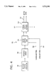
- FIG. 1 A block diagram of this type of prior art linear cryogenic cooling system is shown in FIG. 1.
- the Supply Voltage 12 applied to Voltage Regulator 14 can be either a fixed or a variable DC voltage. Adjustable Voltage Regulator 14 produces Voltage Regulator output signal 24, the magnitude of which is controlled by Temperature Sensor Feedback signal 30. Voltage Regulator output signal 24 is applied to Motor Driver 16, which is an electronic switching circuit which produces Motor Driver output signal 26. A typical waveshape of Motor Driver output signal 26 is also shown in FIG. 1. Motor Driver output signal 26 is applied to and controls Cooler Motor 18. Cooler Motor 18 is used to remove heat from a target device, and the actual temperature of the target device to be cooled is monitored by Temperature Sensor 20.
- Temperature Sensor 20 The output signal of Temperature Sensor 20 is Temperature Sensor signal 28, which represents a measure of the target device temperature.
- Temperature Sensor Feedback 22 modifies Temperature Sensor signal 28 as required for proper closed-loop operation, and produces Temperature Sensor Feedback signal 30.
- Temperature Sensor Feedback signal 30 is applied to Voltage Regulator 14 and is used to vary the value of Voltage Regulator output signal 24 as required to maintain constant target device temperature, thereby controlling the setpoint of Voltage Regulator 14.
- One disadvantage of a cooling system based on this prior art approach is the large amount of power dissipated in Voltage Regulator 14 and the associated heat generated. Using a voltage regulator in this manner is power inefficient; with 10% to 20% loss in efficiency of Voltage Regulator 14 being common.
- a highly efficient motor driver circuit of an electronic controller for linear cryogenic coolers operates directly from a variable power supply, such as a battery, without the need for the voltage regulator control circuit of the prior art. Elimination of the prior art voltage regulator ensures a higher efficiency motor driver circuit of the electronic controller.
- the present invention has both open-loop and closed-loop controllers for electronically controlling the cooler motor used in linear cryogenic coolers.
- the open-loop controller protects against temperature sensor failure, and will limit maximum motor power as a function of system ambient temperature.
- the closed-loop controller regulates the temperature of the cold finger accurately to a preset value, using feedback from a temperature sensor along with a novel pulse-width modulation concept for modifying motor drive waveforms. Because pulse-width modulation, not amplitude modulation, is used to vary motor power, the techniques of this invention are impervious to the magnitude of available source voltage, which allows for the wide-range operation typically encountered in battery applications. Because higher efficiency is achieved and thus less heat is generated, a high degree of miniaturization is practical.
- FIG. 1 is a Cooling System Block Diagram, according to the prior art
- FIG. 2 is a Cooler Control System Block Diagram, according to a preferred embodiment of the present invention.
- FIG. 3 is an Electronic Controller Block Diagram, according to a preferred embodiment of the present invention.
- FIG. 4 is a Motor Driver Block Diagram, according to a preferred embodiment of the present invention.
- FIG. 5 is a graph of a Motor Drive Waveform, for description of the preferred embodiment
- FIG. 6 is an Open-Loop Controller Block Diagram, according to a preferred embodiment of the present invention.
- FIG. 7 is a graph of Typical Motor Power Limits (Open-Loop), for description of the preferred embodiment
- FIG. 8 is a Closed-Loop Controller Block Diagram, according to a preferred embodiment of the present invention.
- FIG. 9 is a graph of Motor Drive with Modulation, for description of the preferred embodiment.
- FIG. 10 is a graph of Output Pressure Waveform, for description of the preferred embodiment.
- FIG. 11 is a graph of Temperature Control Zone vs. Pulse-Width Modulation, for description of the preferred embodiment.
- the cooler control system 10 consists of Motor/Compressor Assembly 52, DEWAR Assembly 54 and Electronic Controller 56.
- Motor/Compressor Assembly 52 contains Motor 60 and Compressor 62.
- DEWAR Assembly 54 an insulated assembly, contains Cold Finger 66, Infrared Detectors 67, and Temperature Sensor 68.
- Electronic Controller 56 contains electronics circuitry which will be discussed later.
- Voltage Source 58 is typically approximately 17-32 VDC, although other voltage ranges may be utilized.
- Motor/Compressor Assembly 52 is connected to Cold Finger 66 by Transfer Line 64.
- Cold Finger 66 interfaces with DEWAR Assembly 54 which is a vacuum-jacketed glass tube that insulates Cold Finger 66 which is -193° Celsius or 80° Kelvin from surrounding ambient temperatures which are considerably warmer.
- Infrared Detectors 67 and Temperature Sensor 68 are attached on the vacuum side of the glass tube that is DEWAR Assembly 54.
- the Cold Finger 66 generates the refrigeration required to cool the Infrared Detectors 67 to their required operating temperature.
- Electronic Controller 56 interfaces to Motor/Compressor Assembly 52 and DEWAR Assembly 54 detector assembly, and provides the necessary controls to regulate the detector's temperature to a preset value.
- Temperature Sensor Signal 70 electrically represents target device temperature and is applied as an input signal to Electronic Controller 56.
- Electronic Controller Block Diagram 100 consists of four main sections: EMI Filter 104, Motor Driver 106, Closed-loop Controller 110 and Open-loop Controller 112.
- EMI Filter 104 provides electrical filtering to remove noise from Voltage Supply 102.
- Motor Driver 106 electronically converts the output signal pair of EMI Filter 104 to a phased 60 Hz drive signal pair which is Motor Drive output signal pair 122.
- Motor Drive output signal pair 122 drives the Motor/Compressor Assembly 52 of FIG. 2.
- Motor Drive output signal pair 122 is controlled by two controllers, Closed-Loop Controller 110 and Open-Loop Controller 112.
- the output signal 116 of Closed-Loop Controller 110 regulates DEWAR temperature by monitoring Temperature Sensor signal 114 and modulating 60 Hz Motor Drive output signal pair 122 which results in variation of the stroke of the compressor to change the amount of cooling supplied to the cold finger in order to regulate the temperature of the cold finger.
- Open-Loop Controller 112 provides a maximum power limit that the Motor 60 can use during cold finger cool-down or in the event of a cold finger temperature sensor failure.
- Open-Loop Controller 112 monitors the current through the Motor 60 of FIG. 2 by using the output signal of Current Sensor 108, and results in modulation of Motor Drive Output 122 when a preset limit is reached. By limiting the amount of current the motor can draw, maximum motor power can be controlled.
- the block diagram in FIG. 4 further explains Motor Driver 106.
- the motor resonance frequency selected is 60 Hz.
- Crystal Oscillator 160 is set to oscillate at 30.72 KHz, although other frequencies may be used depending on motor characteristics and Frequency Divider 158. A very stable oscillator is required to maintain this frequency over the environmental conditions in which many coolers operate.
- the output signal of Crystal Oscillator 160 is divided down by Frequency Divider 158 to 60 Hz in this example.
- Motor Control Logic 156 is then used to operate H-Bridge Switch Network 154, which generates Motor Drive output signal 152 which cycles the current through the motor coils, which is the waveform shown in FIG. 5. In the waveforms of FIG. 5, during interval A the motor coils will be pulled in towards each other.
- interval B the current is reversed and the motor coils are forced apart.
- Interval C allows the energy in the coils to dissipate, thereby preventing large voltage spikes from occurring when reversing the current to the coils.
- Inputs to the motor driver are Closed-Loop PWM 162 and Open-Loop PWM 164, where PWM is Pulse-Width Modulation. Closed-Loop PWM 162 and Open-Loop PWM 164 are signals which are analogous to signal 116 and 118, respectively, of FIG. 3.
- Open-Loop Controller 200 limits the power to the motor at normal ambient temperature, and increases the power limit at elevated temperatures. This limit is maintained over a variable supply voltage range and variable load conditions.
- Motor Current Sensor 202 continuously monitors current through the motor coils.
- the sensor is typically a resistor placed in the low side of the motor driver, such as Current Sensor 108 of FIG. 3. As motor current flows through the resistor, a proportional voltage is developed across the resistor. Because it is a pulsed waveform, this voltage must be filtered by Filter/Amplifier 204, the characteristics of which are selected to obtain the fastest system response time to prevent overshoots and still provide smooth steady state operation.
- the output signal 205 of Filter/Amplifier 204 is then applied to Voltage Multiplier 208 where it is multiplied by Supply Voltage Monitor 206 to produce output signal 209.
- Output signal 209 is then applied to Error Amplifier 214, where output signal 209 is compared to the Preset Power Limit signal 213 obtained from Power Level Reference 212 and Ambient Temperature Monitor 210.
- the output signal 215 of Error Amplifier 214 is applied to Pulse-Width Modulator 216 which varies Pulse-Width Modulator Output signal 218 and throttles back the motor to maintain the preset power limit.
- the preset power limit is controlled by Ambient Temperature Monitor 210 which increases the setpoint as the cooler's ambient temperature increases. High and low limits are designed in to limit power independently at room and high temperatures. An example of this type of control is shown in FIG. 7. Open-loop PWM signal 218 of FIG. 6 is equal to Open-loop PWM signal 164 of FIG.
- Sensor Current Driver 260 provides a constant bias source to bias Detector Temperature Sensor 262 so as to produce a voltage dependent only on temperature.
- Temperature Sensor Signal Amplifier 258 is used to measure the output of Detector Temperature Sensor 262.
- Error Amplifier 256 compares the output signal 259 of Temperature Sensor Signal Amplifier 258 to Temperature Setpoint Reference 252 which is selected to correspond to the desired control setpoint.
- Pulse-Width Modulator 254 receives the output signal 255 of Error Amplifier 256 and converts it to a controlled pulse width which is dependent on the magnitude of the error.
- Closed-Loop PWM 266 controls the motor by pulsing the on intervals of the motor drive signal utilizing pulses of variable width.
- FIG. 9 shows a motor drive waveform with modulation to illustrate the modulation technique of the motor driver.
- the required pulse width is dependent on cooling capacity and heat load. The larger the cooling capacity or the smaller the heat load, the shorter the pulse width. A shorter pulse width shortens the period of time voltage is applied to the motor.
- the cooler control loops described will reach steady-state operating conditions when the cold finger reaches the desired cryogenic temperature, and this operating point will automatically be maintained by vernier adjustment of modulating pulse width.
- Pulse-Width Modulator 254 frequency is selected to give a pulse width much smaller than the motor electrical and mechanical time constants to ensure smooth motor operation.
- FIG. 10 shows the output pressure waveform of a motor/compressor driven by Closed-Loop PWM 266.
- the control zone for the cooler system was set at 100% pulse width for the low frequency end, and 10% pulse width for the high frequency end. These end points are connected linearly, with the normal temperature set at a 50% duty cycle. This places the nominal temperature setpoint in approximately the middle of the control zone.
- the control zone is shown in FIG. 11.
Abstract
Description
Claims (22)
Priority Applications (6)
| Application Number | Priority Date | Filing Date | Title |
|---|---|---|---|
| US08/563,938 US5752385A (en) | 1995-11-29 | 1995-11-29 | Electronic controller for linear cryogenic coolers |
| CA002186306A CA2186306C (en) | 1995-11-29 | 1996-09-24 | Electronic controller for linear cryogenic coolers |
| JP8288913A JPH09222357A (en) | 1995-11-29 | 1996-10-31 | Electronic control device for linear low-temperature cooler |
| EP96117763A EP0778508B1 (en) | 1995-11-29 | 1996-11-06 | Electronic controller for linear cryogenic coolers |
| DE69608529T DE69608529T2 (en) | 1995-11-29 | 1996-11-06 | Electronic control for linear cryogenic coolers |
| KR1019960056367A KR100426509B1 (en) | 1995-11-29 | 1996-11-22 | Control system and control circuit for linear low temperature cooler |
Applications Claiming Priority (1)
| Application Number | Priority Date | Filing Date | Title |
|---|---|---|---|
| US08/563,938 US5752385A (en) | 1995-11-29 | 1995-11-29 | Electronic controller for linear cryogenic coolers |
Publications (1)
| Publication Number | Publication Date |
|---|---|
| US5752385A true US5752385A (en) | 1998-05-19 |
Family
ID=24252512
Family Applications (1)
| Application Number | Title | Priority Date | Filing Date |
|---|---|---|---|
| US08/563,938 Expired - Lifetime US5752385A (en) | 1995-11-29 | 1995-11-29 | Electronic controller for linear cryogenic coolers |
Country Status (6)
| Country | Link |
|---|---|
| US (1) | US5752385A (en) |
| EP (1) | EP0778508B1 (en) |
| JP (1) | JPH09222357A (en) |
| KR (1) | KR100426509B1 (en) |
| CA (1) | CA2186306C (en) |
| DE (1) | DE69608529T2 (en) |
Cited By (51)
| Publication number | Priority date | Publication date | Assignee | Title |
|---|---|---|---|---|
| US6233947B1 (en) * | 1999-11-02 | 2001-05-22 | Bei Sensors & Systems, Inc. | High efficiency fuzzy logic based stirling cycle cryogenic cooler |
| US6289680B1 (en) * | 1998-11-04 | 2001-09-18 | Lg Electronics, Inc. | Apparatus for controlling linear compressor and method thereof |
| US6601397B2 (en) | 2001-03-16 | 2003-08-05 | Copeland Corporation | Digital scroll condensing unit controller |
| US20050076659A1 (en) * | 2003-08-25 | 2005-04-14 | Wallace John G. | Refrigeration control system |
| US20050210889A1 (en) * | 2004-03-29 | 2005-09-29 | Bayram Arman | Method for operating a cryocooler using temperature trending monitoring |
| US20060101836A1 (en) * | 2002-08-20 | 2006-05-18 | Hidekazu Tanaka | Very low temperature refrigerator |
| WO2005106351A3 (en) * | 2004-04-15 | 2007-02-01 | Sunpower Inc | Temperature control for cryocooler with gas bearings |
| US20070089435A1 (en) * | 2005-10-21 | 2007-04-26 | Abtar Singh | Predicting maintenance in a refrigeration system |
| US20070089439A1 (en) * | 2005-10-21 | 2007-04-26 | Abtar Singh | Monitoring a condenser in a refrigeration system |
| US20070089436A1 (en) * | 2005-10-21 | 2007-04-26 | Abtar Singh | Monitoring refrigerant in a refrigeration system |
| US20070089437A1 (en) * | 2005-10-21 | 2007-04-26 | Abtar Singh | Proofing a refrigeration system operating state |
| US20070169476A1 (en) * | 2006-01-24 | 2007-07-26 | Wood Jonathan R | System and method for electrically-coupled thermal cycle |
| US20070277550A1 (en) * | 2000-08-09 | 2007-12-06 | Cryocor, Inc. | Refrigeration source for a cryoablation catheter |
| USRE40815E1 (en) | 1999-06-25 | 2009-06-30 | Ams Research Corporation | Control system for cryosurgery |
| US20090229279A1 (en) * | 2005-06-17 | 2009-09-17 | Monica Dalla Valle | Method for cool drying |
| US20090266091A1 (en) * | 2005-08-03 | 2009-10-29 | Bristol Compressors International, Inc. | System and method for compressor capacity modulation in a heat pump |
| US20090324426A1 (en) * | 2008-06-29 | 2009-12-31 | Moody Bruce A | Compressor speed control system for bearing reliability |
| US7644591B2 (en) | 2001-05-03 | 2010-01-12 | Emerson Retail Services, Inc. | System for remote refrigeration monitoring and diagnostics |
| US20100083680A1 (en) * | 2005-08-03 | 2010-04-08 | Tolbert Jr John W | System for compressor capacity modulation |
| US7727228B2 (en) | 2004-03-23 | 2010-06-01 | Medtronic Cryocath Lp | Method and apparatus for inflating and deflating balloon catheters |
| US7752853B2 (en) | 2005-10-21 | 2010-07-13 | Emerson Retail Services, Inc. | Monitoring refrigerant in a refrigeration system |
| US7885959B2 (en) | 2005-02-21 | 2011-02-08 | Computer Process Controls, Inc. | Enterprise controller display method |
| US20110110791A1 (en) * | 2008-07-25 | 2011-05-12 | Carrier Corporation | Continuous compressor envelope protection |
| US20110174271A1 (en) * | 2010-01-19 | 2011-07-21 | Altor Limited Lc | System and method for electrically-coupled heat engine and thermal cycle |
| US8206345B2 (en) | 2005-03-07 | 2012-06-26 | Medtronic Cryocath Lp | Fluid control system for a medical device |
| US20130064686A1 (en) * | 2010-04-07 | 2013-03-14 | Webasto SE | Method for operating a dosing pump and device having a dosing pump |
| CN103023325A (en) * | 2012-12-06 | 2013-04-03 | 北京控制工程研究所 | Low-power-consumption control method and circuit |
| US8421368B2 (en) | 2007-07-31 | 2013-04-16 | Lsi Industries, Inc. | Control of light intensity using pulses of a fixed duration and frequency |
| US8473106B2 (en) | 2009-05-29 | 2013-06-25 | Emerson Climate Technologies Retail Solutions, Inc. | System and method for monitoring and evaluating equipment operating parameter modifications |
| US8491636B2 (en) | 2004-03-23 | 2013-07-23 | Medtronic Cryopath LP | Method and apparatus for inflating and deflating balloon catheters |
| US8495886B2 (en) | 2001-05-03 | 2013-07-30 | Emerson Climate Technologies Retail Solutions, Inc. | Model-based alarming |
| US8604709B2 (en) | 2007-07-31 | 2013-12-10 | Lsi Industries, Inc. | Methods and systems for controlling electrical power to DC loads |
| US8601828B2 (en) | 2009-04-29 | 2013-12-10 | Bristol Compressors International, Inc. | Capacity control systems and methods for a compressor |
| WO2014018218A1 (en) * | 2012-07-23 | 2014-01-30 | Global Cooling, Inc. | Vehicle and storage lng systems |
| US8700444B2 (en) | 2002-10-31 | 2014-04-15 | Emerson Retail Services Inc. | System for monitoring optimal equipment operating parameters |
| US8903577B2 (en) | 2009-10-30 | 2014-12-02 | Lsi Industries, Inc. | Traction system for electrically powered vehicles |
| US8964338B2 (en) | 2012-01-11 | 2015-02-24 | Emerson Climate Technologies, Inc. | System and method for compressor motor protection |
| US8974573B2 (en) | 2004-08-11 | 2015-03-10 | Emerson Climate Technologies, Inc. | Method and apparatus for monitoring a refrigeration-cycle system |
| US9121407B2 (en) | 2004-04-27 | 2015-09-01 | Emerson Climate Technologies, Inc. | Compressor diagnostic and protection system and method |
| US9140728B2 (en) | 2007-11-02 | 2015-09-22 | Emerson Climate Technologies, Inc. | Compressor sensor module |
| US9285802B2 (en) | 2011-02-28 | 2016-03-15 | Emerson Electric Co. | Residential solutions HVAC monitoring and diagnosis |
| US9310439B2 (en) | 2012-09-25 | 2016-04-12 | Emerson Climate Technologies, Inc. | Compressor having a control and diagnostic module |
| US9310094B2 (en) | 2007-07-30 | 2016-04-12 | Emerson Climate Technologies, Inc. | Portable method and apparatus for monitoring refrigerant-cycle systems |
| US9551504B2 (en) | 2013-03-15 | 2017-01-24 | Emerson Electric Co. | HVAC system remote monitoring and diagnosis |
| US9638436B2 (en) | 2013-03-15 | 2017-05-02 | Emerson Electric Co. | HVAC system remote monitoring and diagnosis |
| US9765979B2 (en) | 2013-04-05 | 2017-09-19 | Emerson Climate Technologies, Inc. | Heat-pump system with refrigerant charge diagnostics |
| US9803902B2 (en) | 2013-03-15 | 2017-10-31 | Emerson Climate Technologies, Inc. | System for refrigerant charge verification using two condenser coil temperatures |
| US9823632B2 (en) | 2006-09-07 | 2017-11-21 | Emerson Climate Technologies, Inc. | Compressor data module |
| US9885507B2 (en) | 2006-07-19 | 2018-02-06 | Emerson Climate Technologies, Inc. | Protection and diagnostic module for a refrigeration system |
| US10041713B1 (en) | 1999-08-20 | 2018-08-07 | Hudson Technologies, Inc. | Method and apparatus for measuring and improving efficiency in refrigeration systems |
| US20230118157A1 (en) * | 2021-10-16 | 2023-04-20 | Cryo Tech Ltd. | Piston compressor unit of a split stirling cryogenic refrigerator |
Families Citing this family (5)
| Publication number | Priority date | Publication date | Assignee | Title |
|---|---|---|---|---|
| US6330800B1 (en) * | 1999-04-16 | 2001-12-18 | Raytheon Company | Apparatus and method for achieving temperature stability in a two-stage cryocooler |
| BE1016734A3 (en) | 2005-08-25 | 2007-05-08 | Atlas Copco Airpower Nv | IMPROVED DEVICE FOR COOLING. |
| US20090058327A1 (en) * | 2007-08-28 | 2009-03-05 | Vladimir Maron | Pumping driver for linear motor with constant battery power/current |
| JP6187432B2 (en) * | 2014-11-14 | 2017-08-30 | 株式会社デンソー | Control device |
| CN111213018B (en) | 2017-10-11 | 2022-07-15 | 泰立戴恩菲力尔商业系统公司 | Refrigerator controller system and method |
Citations (4)
| Publication number | Priority date | Publication date | Assignee | Title |
|---|---|---|---|---|
| US4361011A (en) * | 1981-09-09 | 1982-11-30 | The United States Of America As Represented By The Secretary Of The Army | Cryogenic cooling system |
| US5018357A (en) * | 1988-10-11 | 1991-05-28 | Helix Technology Corporation | Temperature control system for a cryogenic refrigeration |
| US5531074A (en) * | 1994-03-09 | 1996-07-02 | Japan Atomic Energy Research Institute | Electronic device freezed by intermittently driven refrigerator |
| US5572879A (en) * | 1995-05-25 | 1996-11-12 | Thermo King Corporation | Methods of operating a refrigeration unit in predetermined high and low ambient temperatures |
Family Cites Families (4)
| Publication number | Priority date | Publication date | Assignee | Title |
|---|---|---|---|---|
| US4679401A (en) * | 1985-07-03 | 1987-07-14 | Helix Technology Corporation | Temperature control of cryogenic systems |
| US4664685A (en) * | 1985-11-19 | 1987-05-12 | Helix Technology Corporation | Linear drive motor control in a cryogenic refrigerator |
| US5023531A (en) * | 1988-05-19 | 1991-06-11 | Arx, Inc. | Dual hybrid demand refrigeration control apparatus |
| US5156005A (en) * | 1991-05-24 | 1992-10-20 | Sunpower, Inc. | Control of stirling cooler displacement by pulse width modulation of drive motor voltage |
-
1995
- 1995-11-29 US US08/563,938 patent/US5752385A/en not_active Expired - Lifetime
-
1996
- 1996-09-24 CA CA002186306A patent/CA2186306C/en not_active Expired - Fee Related
- 1996-10-31 JP JP8288913A patent/JPH09222357A/en not_active Abandoned
- 1996-11-06 DE DE69608529T patent/DE69608529T2/en not_active Expired - Lifetime
- 1996-11-06 EP EP96117763A patent/EP0778508B1/en not_active Expired - Lifetime
- 1996-11-22 KR KR1019960056367A patent/KR100426509B1/en not_active IP Right Cessation
Patent Citations (4)
| Publication number | Priority date | Publication date | Assignee | Title |
|---|---|---|---|---|
| US4361011A (en) * | 1981-09-09 | 1982-11-30 | The United States Of America As Represented By The Secretary Of The Army | Cryogenic cooling system |
| US5018357A (en) * | 1988-10-11 | 1991-05-28 | Helix Technology Corporation | Temperature control system for a cryogenic refrigeration |
| US5531074A (en) * | 1994-03-09 | 1996-07-02 | Japan Atomic Energy Research Institute | Electronic device freezed by intermittently driven refrigerator |
| US5572879A (en) * | 1995-05-25 | 1996-11-12 | Thermo King Corporation | Methods of operating a refrigeration unit in predetermined high and low ambient temperatures |
Cited By (111)
| Publication number | Priority date | Publication date | Assignee | Title |
|---|---|---|---|---|
| US6289680B1 (en) * | 1998-11-04 | 2001-09-18 | Lg Electronics, Inc. | Apparatus for controlling linear compressor and method thereof |
| USRE40815E1 (en) | 1999-06-25 | 2009-06-30 | Ams Research Corporation | Control system for cryosurgery |
| USRE40868E1 (en) | 1999-06-25 | 2009-08-11 | Cryocor, Inc. | Refrigeration source for a cryoblation catheter |
| US10041713B1 (en) | 1999-08-20 | 2018-08-07 | Hudson Technologies, Inc. | Method and apparatus for measuring and improving efficiency in refrigeration systems |
| US6233947B1 (en) * | 1999-11-02 | 2001-05-22 | Bei Sensors & Systems, Inc. | High efficiency fuzzy logic based stirling cycle cryogenic cooler |
| US20070277550A1 (en) * | 2000-08-09 | 2007-12-06 | Cryocor, Inc. | Refrigeration source for a cryoablation catheter |
| US6601397B2 (en) | 2001-03-16 | 2003-08-05 | Copeland Corporation | Digital scroll condensing unit controller |
| US6745584B2 (en) | 2001-03-16 | 2004-06-08 | Copeland Corporation | Digital scroll condensing unit controller |
| US7644591B2 (en) | 2001-05-03 | 2010-01-12 | Emerson Retail Services, Inc. | System for remote refrigeration monitoring and diagnostics |
| US8316658B2 (en) | 2001-05-03 | 2012-11-27 | Emerson Climate Technologies Retail Solutions, Inc. | Refrigeration system energy monitoring and diagnostics |
| US8065886B2 (en) | 2001-05-03 | 2011-11-29 | Emerson Retail Services, Inc. | Refrigeration system energy monitoring and diagnostics |
| US8495886B2 (en) | 2001-05-03 | 2013-07-30 | Emerson Climate Technologies Retail Solutions, Inc. | Model-based alarming |
| US20060101836A1 (en) * | 2002-08-20 | 2006-05-18 | Hidekazu Tanaka | Very low temperature refrigerator |
| US7555911B2 (en) * | 2002-08-20 | 2009-07-07 | Sumitomo Heavy Industries, Ltd. | Cryogenic refrigerator |
| US8700444B2 (en) | 2002-10-31 | 2014-04-15 | Emerson Retail Services Inc. | System for monitoring optimal equipment operating parameters |
| US20050076659A1 (en) * | 2003-08-25 | 2005-04-14 | Wallace John G. | Refrigeration control system |
| US7727228B2 (en) | 2004-03-23 | 2010-06-01 | Medtronic Cryocath Lp | Method and apparatus for inflating and deflating balloon catheters |
| US8491636B2 (en) | 2004-03-23 | 2013-07-23 | Medtronic Cryopath LP | Method and apparatus for inflating and deflating balloon catheters |
| US8545491B2 (en) | 2004-03-23 | 2013-10-01 | Medtronic Cryocath Lp | Method and apparatus for inflating and deflating balloon catheters |
| US7249465B2 (en) * | 2004-03-29 | 2007-07-31 | Praxair Technology, Inc. | Method for operating a cryocooler using temperature trending monitoring |
| WO2005098329A3 (en) * | 2004-03-29 | 2006-12-21 | Praxair Technology Inc | Cryocooler operation using temperature trending monitoring |
| WO2005098329A2 (en) * | 2004-03-29 | 2005-10-20 | Praxair Technology, Inc. | Cryocooler operation using temperature trending monitoring |
| US20050210889A1 (en) * | 2004-03-29 | 2005-09-29 | Bayram Arman | Method for operating a cryocooler using temperature trending monitoring |
| US7266947B2 (en) * | 2004-04-15 | 2007-09-11 | Sunpower, Inc. | Temperature control for free-piston cryocooler with gas bearings |
| WO2005106351A3 (en) * | 2004-04-15 | 2007-02-01 | Sunpower Inc | Temperature control for cryocooler with gas bearings |
| US10335906B2 (en) | 2004-04-27 | 2019-07-02 | Emerson Climate Technologies, Inc. | Compressor diagnostic and protection system and method |
| US9121407B2 (en) | 2004-04-27 | 2015-09-01 | Emerson Climate Technologies, Inc. | Compressor diagnostic and protection system and method |
| US9669498B2 (en) | 2004-04-27 | 2017-06-06 | Emerson Climate Technologies, Inc. | Compressor diagnostic and protection system and method |
| US9081394B2 (en) | 2004-08-11 | 2015-07-14 | Emerson Climate Technologies, Inc. | Method and apparatus for monitoring a refrigeration-cycle system |
| US9046900B2 (en) | 2004-08-11 | 2015-06-02 | Emerson Climate Technologies, Inc. | Method and apparatus for monitoring refrigeration-cycle systems |
| US9304521B2 (en) | 2004-08-11 | 2016-04-05 | Emerson Climate Technologies, Inc. | Air filter monitoring system |
| US8974573B2 (en) | 2004-08-11 | 2015-03-10 | Emerson Climate Technologies, Inc. | Method and apparatus for monitoring a refrigeration-cycle system |
| US9017461B2 (en) | 2004-08-11 | 2015-04-28 | Emerson Climate Technologies, Inc. | Method and apparatus for monitoring a refrigeration-cycle system |
| US10558229B2 (en) | 2004-08-11 | 2020-02-11 | Emerson Climate Technologies Inc. | Method and apparatus for monitoring refrigeration-cycle systems |
| US9023136B2 (en) | 2004-08-11 | 2015-05-05 | Emerson Climate Technologies, Inc. | Method and apparatus for monitoring a refrigeration-cycle system |
| US9690307B2 (en) | 2004-08-11 | 2017-06-27 | Emerson Climate Technologies, Inc. | Method and apparatus for monitoring refrigeration-cycle systems |
| US9086704B2 (en) | 2004-08-11 | 2015-07-21 | Emerson Climate Technologies, Inc. | Method and apparatus for monitoring a refrigeration-cycle system |
| US9021819B2 (en) | 2004-08-11 | 2015-05-05 | Emerson Climate Technologies, Inc. | Method and apparatus for monitoring a refrigeration-cycle system |
| US7885959B2 (en) | 2005-02-21 | 2011-02-08 | Computer Process Controls, Inc. | Enterprise controller display method |
| US7885961B2 (en) | 2005-02-21 | 2011-02-08 | Computer Process Controls, Inc. | Enterprise control and monitoring system and method |
| US8206345B2 (en) | 2005-03-07 | 2012-06-26 | Medtronic Cryocath Lp | Fluid control system for a medical device |
| US9216378B2 (en) * | 2005-06-17 | 2015-12-22 | Atlas Copco Airpower, Naamloze Vennootschap | Method for cool drying gas |
| US20090229279A1 (en) * | 2005-06-17 | 2009-09-17 | Monica Dalla Valle | Method for cool drying |
| US7946123B2 (en) | 2005-08-03 | 2011-05-24 | Bristol Compressors International, Inc. | System for compressor capacity modulation |
| US8650894B2 (en) | 2005-08-03 | 2014-02-18 | Bristol Compressors International, Inc. | System and method for compressor capacity modulation in a heat pump |
| US20090266091A1 (en) * | 2005-08-03 | 2009-10-29 | Bristol Compressors International, Inc. | System and method for compressor capacity modulation in a heat pump |
| US20100083680A1 (en) * | 2005-08-03 | 2010-04-08 | Tolbert Jr John W | System for compressor capacity modulation |
| US20070089435A1 (en) * | 2005-10-21 | 2007-04-26 | Abtar Singh | Predicting maintenance in a refrigeration system |
| US7665315B2 (en) | 2005-10-21 | 2010-02-23 | Emerson Retail Services, Inc. | Proofing a refrigeration system operating state |
| US20070089439A1 (en) * | 2005-10-21 | 2007-04-26 | Abtar Singh | Monitoring a condenser in a refrigeration system |
| US20070089436A1 (en) * | 2005-10-21 | 2007-04-26 | Abtar Singh | Monitoring refrigerant in a refrigeration system |
| US7752854B2 (en) | 2005-10-21 | 2010-07-13 | Emerson Retail Services, Inc. | Monitoring a condenser in a refrigeration system |
| US7752853B2 (en) | 2005-10-21 | 2010-07-13 | Emerson Retail Services, Inc. | Monitoring refrigerant in a refrigeration system |
| US20070089437A1 (en) * | 2005-10-21 | 2007-04-26 | Abtar Singh | Proofing a refrigeration system operating state |
| US20100115941A1 (en) * | 2006-01-24 | 2010-05-13 | Altor Limited Lc | System and Method for Electrically-Coupled Thermal Cycle |
| US20100115942A1 (en) * | 2006-01-24 | 2010-05-13 | Altor Limited Lc | System and Method for Electrically-Coupled Thermal Cycle |
| US8196402B2 (en) | 2006-01-24 | 2012-06-12 | Altor Limited Lc | System and method for electrically-coupled thermal cycle |
| US8701404B2 (en) | 2006-01-24 | 2014-04-22 | Altor Limited Lc | System and method for electrically-coupled thermal cycle |
| US8720198B2 (en) | 2006-01-24 | 2014-05-13 | Altor Limited Lc | System and method for electrically-coupled thermal cycle |
| US20070169476A1 (en) * | 2006-01-24 | 2007-07-26 | Wood Jonathan R | System and method for electrically-coupled thermal cycle |
| US7690199B2 (en) | 2006-01-24 | 2010-04-06 | Altor Limited Lc | System and method for electrically-coupled thermal cycle |
| US20100127506A1 (en) * | 2006-01-24 | 2010-05-27 | Altor Limited Lc | System and Method for Electrically-Coupled Thermal Cycle |
| US9885507B2 (en) | 2006-07-19 | 2018-02-06 | Emerson Climate Technologies, Inc. | Protection and diagnostic module for a refrigeration system |
| US9823632B2 (en) | 2006-09-07 | 2017-11-21 | Emerson Climate Technologies, Inc. | Compressor data module |
| US9310094B2 (en) | 2007-07-30 | 2016-04-12 | Emerson Climate Technologies, Inc. | Portable method and apparatus for monitoring refrigerant-cycle systems |
| US10352602B2 (en) | 2007-07-30 | 2019-07-16 | Emerson Climate Technologies, Inc. | Portable method and apparatus for monitoring refrigerant-cycle systems |
| US8604709B2 (en) | 2007-07-31 | 2013-12-10 | Lsi Industries, Inc. | Methods and systems for controlling electrical power to DC loads |
| US8421368B2 (en) | 2007-07-31 | 2013-04-16 | Lsi Industries, Inc. | Control of light intensity using pulses of a fixed duration and frequency |
| US9140728B2 (en) | 2007-11-02 | 2015-09-22 | Emerson Climate Technologies, Inc. | Compressor sensor module |
| US9194894B2 (en) | 2007-11-02 | 2015-11-24 | Emerson Climate Technologies, Inc. | Compressor sensor module |
| US10458404B2 (en) | 2007-11-02 | 2019-10-29 | Emerson Climate Technologies, Inc. | Compressor sensor module |
| US20090324428A1 (en) * | 2008-06-29 | 2009-12-31 | Tolbert Jr John W | System and method for detecting a fault condition in a compressor |
| US20090324427A1 (en) * | 2008-06-29 | 2009-12-31 | Tolbert Jr John W | System and method for starting a compressor |
| US20090324426A1 (en) * | 2008-06-29 | 2009-12-31 | Moody Bruce A | Compressor speed control system for bearing reliability |
| US8904814B2 (en) | 2008-06-29 | 2014-12-09 | Bristol Compressors, International Inc. | System and method for detecting a fault condition in a compressor |
| US8790089B2 (en) | 2008-06-29 | 2014-07-29 | Bristol Compressors International, Inc. | Compressor speed control system for bearing reliability |
| US8672642B2 (en) | 2008-06-29 | 2014-03-18 | Bristol Compressors International, Inc. | System and method for starting a compressor |
| US20110110791A1 (en) * | 2008-07-25 | 2011-05-12 | Carrier Corporation | Continuous compressor envelope protection |
| US8601828B2 (en) | 2009-04-29 | 2013-12-10 | Bristol Compressors International, Inc. | Capacity control systems and methods for a compressor |
| US8473106B2 (en) | 2009-05-29 | 2013-06-25 | Emerson Climate Technologies Retail Solutions, Inc. | System and method for monitoring and evaluating equipment operating parameter modifications |
| US9395711B2 (en) | 2009-05-29 | 2016-07-19 | Emerson Climate Technologies Retail Solutions, Inc. | System and method for monitoring and evaluating equipment operating parameter modifications |
| US8761908B2 (en) | 2009-05-29 | 2014-06-24 | Emerson Climate Technologies Retail Solutions, Inc. | System and method for monitoring and evaluating equipment operating parameter modifications |
| US8903577B2 (en) | 2009-10-30 | 2014-12-02 | Lsi Industries, Inc. | Traction system for electrically powered vehicles |
| US9228490B2 (en) | 2010-01-19 | 2016-01-05 | Altor Limited Lc | System and method for electrically-coupled heat engine and thermal cycle |
| US20110174271A1 (en) * | 2010-01-19 | 2011-07-21 | Altor Limited Lc | System and method for electrically-coupled heat engine and thermal cycle |
| US8726857B2 (en) | 2010-01-19 | 2014-05-20 | Altor Limited Lc | System and method for electrically-coupled heat engine and thermal cycle |
| US8991340B2 (en) | 2010-01-19 | 2015-03-31 | Altor Limited Lc | System and method for electrically-coupled heat engine and thermal cycle |
| US9599103B2 (en) * | 2010-04-07 | 2017-03-21 | Webasto SE | Method for operating a dosing pump and device having a dosing pump |
| US20130064686A1 (en) * | 2010-04-07 | 2013-03-14 | Webasto SE | Method for operating a dosing pump and device having a dosing pump |
| US10234854B2 (en) | 2011-02-28 | 2019-03-19 | Emerson Electric Co. | Remote HVAC monitoring and diagnosis |
| US9703287B2 (en) | 2011-02-28 | 2017-07-11 | Emerson Electric Co. | Remote HVAC monitoring and diagnosis |
| US10884403B2 (en) | 2011-02-28 | 2021-01-05 | Emerson Electric Co. | Remote HVAC monitoring and diagnosis |
| US9285802B2 (en) | 2011-02-28 | 2016-03-15 | Emerson Electric Co. | Residential solutions HVAC monitoring and diagnosis |
| US8964338B2 (en) | 2012-01-11 | 2015-02-24 | Emerson Climate Technologies, Inc. | System and method for compressor motor protection |
| US9590413B2 (en) | 2012-01-11 | 2017-03-07 | Emerson Climate Technologies, Inc. | System and method for compressor motor protection |
| US9876346B2 (en) | 2012-01-11 | 2018-01-23 | Emerson Climate Technologies, Inc. | System and method for compressor motor protection |
| WO2014018218A1 (en) * | 2012-07-23 | 2014-01-30 | Global Cooling, Inc. | Vehicle and storage lng systems |
| US9762168B2 (en) | 2012-09-25 | 2017-09-12 | Emerson Climate Technologies, Inc. | Compressor having a control and diagnostic module |
| US9310439B2 (en) | 2012-09-25 | 2016-04-12 | Emerson Climate Technologies, Inc. | Compressor having a control and diagnostic module |
| CN103023325A (en) * | 2012-12-06 | 2013-04-03 | 北京控制工程研究所 | Low-power-consumption control method and circuit |
| CN103023325B (en) * | 2012-12-06 | 2015-11-25 | 北京控制工程研究所 | Low-power-consumptiocontrol control method and circuit |
| US10274945B2 (en) | 2013-03-15 | 2019-04-30 | Emerson Electric Co. | HVAC system remote monitoring and diagnosis |
| US9638436B2 (en) | 2013-03-15 | 2017-05-02 | Emerson Electric Co. | HVAC system remote monitoring and diagnosis |
| US9551504B2 (en) | 2013-03-15 | 2017-01-24 | Emerson Electric Co. | HVAC system remote monitoring and diagnosis |
| US10488090B2 (en) | 2013-03-15 | 2019-11-26 | Emerson Climate Technologies, Inc. | System for refrigerant charge verification |
| US9803902B2 (en) | 2013-03-15 | 2017-10-31 | Emerson Climate Technologies, Inc. | System for refrigerant charge verification using two condenser coil temperatures |
| US10775084B2 (en) | 2013-03-15 | 2020-09-15 | Emerson Climate Technologies, Inc. | System for refrigerant charge verification |
| US10060636B2 (en) | 2013-04-05 | 2018-08-28 | Emerson Climate Technologies, Inc. | Heat pump system with refrigerant charge diagnostics |
| US10443863B2 (en) | 2013-04-05 | 2019-10-15 | Emerson Climate Technologies, Inc. | Method of monitoring charge condition of heat pump system |
| US9765979B2 (en) | 2013-04-05 | 2017-09-19 | Emerson Climate Technologies, Inc. | Heat-pump system with refrigerant charge diagnostics |
| US20230118157A1 (en) * | 2021-10-16 | 2023-04-20 | Cryo Tech Ltd. | Piston compressor unit of a split stirling cryogenic refrigerator |
Also Published As
| Publication number | Publication date |
|---|---|
| CA2186306A1 (en) | 1997-05-30 |
| EP0778508B1 (en) | 2000-05-24 |
| CA2186306C (en) | 1999-07-20 |
| KR100426509B1 (en) | 2004-07-01 |
| DE69608529D1 (en) | 2000-06-29 |
| KR970028268A (en) | 1997-06-24 |
| JPH09222357A (en) | 1997-08-26 |
| EP0778508A3 (en) | 1998-04-01 |
| EP0778508A2 (en) | 1997-06-11 |
| DE69608529T2 (en) | 2001-01-18 |
Similar Documents
| Publication | Publication Date | Title |
|---|---|---|
| US5752385A (en) | Electronic controller for linear cryogenic coolers | |
| US4132086A (en) | Temperature control system for refrigeration apparatus | |
| US4102150A (en) | Control system for refrigeration apparatus | |
| US5690849A (en) | Current control circuit for improved power application and control of thermoelectric devices | |
| CA1093182A (en) | Refrigeration control system | |
| US5682748A (en) | Power control circuit for improved power application and temperature control of low voltage thermoelectric devices | |
| EP0604417B1 (en) | Control of high-side pressure in transcritical vapor compression cycle | |
| US4722669A (en) | Fan speed controller | |
| EP0332927B1 (en) | Controlling superheat in a refrigeration system | |
| CA2063904C (en) | Modulated temperature control for environmental chamber | |
| EP0586495A1 (en) | Control of stirling cooler displacement by pulse width modulation of drive motor voltage | |
| US5757172A (en) | Temperature and current dependent regulated voltage source | |
| US5386708A (en) | Cryogenic vacuum pump with expander speed control | |
| US5320162A (en) | Single pole double throw thermostat for narrow range temperature regulation | |
| US4694228A (en) | Compensation circuit for control system providing pulse width modulated drive signal | |
| US6098409A (en) | Temperature control of high temperature superconducting thin film filter subsystems | |
| EP0250047B1 (en) | Tri-state switching controller for reciprocating linear motors | |
| EP0558192B1 (en) | Analog output electro-pneumatic transducer | |
| US4772838A (en) | Tri-state switching controller for reciprocating linear motors | |
| US4737882A (en) | Proportional solenoid valve control circuit | |
| US6748747B2 (en) | Method and system for temperature regulation of a peltier element | |
| US6107783A (en) | Snowmobile handlebar heater control | |
| US11060776B2 (en) | Method for controlling a refrigeration device | |
| US4013872A (en) | Temperature control device | |
| US5001407A (en) | Speed control apparatus having means for changing reference signal for error signal, depending upon load applied to controlled device |
Legal Events
| Date | Code | Title | Description |
|---|---|---|---|
| AS | Assignment |
Owner name: LITTON SYSTEMS, INCORPORATED, CALIFORNIA Free format text: ASSIGNMENT OF ASSIGNORS INTEREST;ASSIGNOR:NELSON, ARTHUR RANDALL;REEL/FRAME:007790/0502 Effective date: 19951026 |
|
| STCF | Information on status: patent grant |
Free format text: PATENTED CASE |
|
| FEPP | Fee payment procedure |
Free format text: PAYOR NUMBER ASSIGNED (ORIGINAL EVENT CODE: ASPN); ENTITY STATUS OF PATENT OWNER: LARGE ENTITY |
|
| FPAY | Fee payment |
Year of fee payment: 4 |
|
| FEPP | Fee payment procedure |
Free format text: PAYOR NUMBER ASSIGNED (ORIGINAL EVENT CODE: ASPN); ENTITY STATUS OF PATENT OWNER: LARGE ENTITY Free format text: PAYER NUMBER DE-ASSIGNED (ORIGINAL EVENT CODE: RMPN); ENTITY STATUS OF PATENT OWNER: LARGE ENTITY |
|
| AS | Assignment |
Owner name: CARLETON LIFE SUPPORT SYSTEMS, INC., IOWA Free format text: ASSIGNMENT OF ASSIGNORS INTEREST;ASSIGNOR:LITTON SYSTEMS, INC.;REEL/FRAME:016427/0532 Effective date: 20030818 |
|
| FPAY | Fee payment |
Year of fee payment: 8 |
|
| FPAY | Fee payment |
Year of fee payment: 12 |