US5769783A - Surgical retractor stay apparatus - Google Patents
Surgical retractor stay apparatus Download PDFInfo
- Publication number
- US5769783A US5769783A US08/671,405 US67140596A US5769783A US 5769783 A US5769783 A US 5769783A US 67140596 A US67140596 A US 67140596A US 5769783 A US5769783 A US 5769783A
- Authority
- US
- United States
- Prior art keywords
- bore
- handle body
- surgical retractor
- distal end
- elastic member
- Prior art date
- Legal status (The legal status is an assumption and is not a legal conclusion. Google has not performed a legal analysis and makes no representation as to the accuracy of the status listed.)
- Expired - Lifetime
Links
Images


Classifications
-
- A—HUMAN NECESSITIES
- A61—MEDICAL OR VETERINARY SCIENCE; HYGIENE
- A61B—DIAGNOSIS; SURGERY; IDENTIFICATION
- A61B17/00—Surgical instruments, devices or methods, e.g. tourniquets
- A61B17/02—Surgical instruments, devices or methods, e.g. tourniquets for holding wounds open; Tractors
- A61B17/0293—Surgical instruments, devices or methods, e.g. tourniquets for holding wounds open; Tractors with ring member to support retractor elements
-
- A—HUMAN NECESSITIES
- A61—MEDICAL OR VETERINARY SCIENCE; HYGIENE
- A61B—DIAGNOSIS; SURGERY; IDENTIFICATION
- A61B17/00—Surgical instruments, devices or methods, e.g. tourniquets
- A61B17/02—Surgical instruments, devices or methods, e.g. tourniquets for holding wounds open; Tractors
- A61B2017/0287—Surgical instruments, devices or methods, e.g. tourniquets for holding wounds open; Tractors with elastic retracting members connectable to a frame, e.g. hooked elastic wires
Definitions
- the present invention relates to surgical retractors and surgical retractor stays. More particularly, the present invention relates to an improved elastic surgical retractor stay and includes a handle body having separate bore sections that respectively accept an end portion of an elastic member and a hook member for engaging the tissue, wherein the handle body has connecting portions that allow separate spaced apart connections to be made between the elastic member and the handle body as well as between the hook and the handle body.
- the surgeon opens the patient with a scalpel, forming an incision and surgical site. As the surgeon cuts deeper, the operating room staff typically holds tissue away from the operative field using retractors.
- retractors are one piece metallic implements that retract a wound in a non-yielding manner. Manipulation and movement of the surgeon as well as movement caused by contracting muscles or tissues of the patient can result in bruising or tearing of tissue.
- Elastic surgical retractor systems are in commercial use that include elastic stays, each having an elongated elastic member that is typically a hollow length of elastic tubing.
- the elastic tubing provides proximal and distal end portions.
- the distal end portion carries an elongated hook constructed of wire.
- the wire hook has a proximal end that is placed in the distal end of the bore of the hollow tubing.
- a shrink wrap is placed over the hook and tubing to hold the proximal end of the wire hook firmly in position within the bore of the tubing at the distal end.
- the embedded portion of the wire hook member is usually recurved or folded. This folded proximal portion of the wire hook expands the tubing slightly, forming a vertically extended portion that defines a handle.
- a surgical retractor array system is disclosed in U.S. Pat. No. 4,434,791, issued to W. Dale Darnell on Mar. 6, 1984.
- This surgical retractor system comprises an array of standardized, interchangeable, annular retractor frame sections of various shapes of which the end portions are configured to permit the interchangeable, hinged connection of the various shaped frames in forming generally annular retractor units adaptable to conform to fit the surface contours of various patients upon which a surgical operation is to be performed.
- This retractor frame is designed to accept yielding rubber or like elastic stays.
- the frame has a plurality of notches spaced about its periphery.
- the elastic portion of the stay is in the form of a length of hollow elastic tubing adapted to be inserted into one of the notches of the frame and held in place by friction to retract the tissue.
- the hook is a single, curved wire member. It has a folded proximal end that fits the hollow bore of the elastic tube.
- U.S. Pat. No. 4,430,991 issued to W. Dale Darnell, issued on Feb. 14, 1984, discloses a surgical retractor stay with a single tissue holding hook affixed to the elastic hollow tubing member of the stay by a retaining member.
- the retaining member has a body in which the hook shank is embedded with the sharp end of the hook extending from one end of the body.
- a stud with a tapered knob on its outer end extends outwardly from the other end of the retaining member body. The size and configuration of the knob and stud enable them to be tightly retained within an end portion of the hollow tubing that is stretchingly installed thereover.
- a surgical tube connector for joining a pair of hollow elastic surgical tube members having an elongated stud with tapered knobs at each end in which the stud and knobs are dimensioned for tight fitting containment within the end portions of the hollow tube members stretchingly installed thereover.
- the present invention provides an improved surgical stay apparatus that can be connected to a frame placed upon the patient's body at a surgical site.
- the frame can provide a plurality of notches that receive an end portion of an elastic member.
- a handle body provides proximal and distal ends, a first bore that extends through the handle body communicating at least with the proximal end of the handle body, the first bore provides a central longitudinal axis.
- a second bore extends at least a partial distance through the handle body and communicates with the proximal surface of the body.
- the elastic member extends through the first bore of the handle body.
- the elastic member has an elongated portion that extends away from the distal end of the handle body and a short proximal end portion that is positioned at the handle body by occupying at least a portion of the first bore.
- a retracting hook has proximal and distal end portions.
- the proximal end portion occupies the second bore of the handle body.
- the hook member has a curved hook at its distal end of the handle body for engaging tissue during retraction.
- the first bore has a linear central longitudinal axis.
- a plug forms a connection with an end portion of the elastic member at one of the bores in the first embodiment (see FIG. 2A).
- the proximal end of the hook engages an offset that forms an anchor within the second bore.
- the first bore includes two separate sections that are generally parallel to one another (see FIG. 4). The elastic member folds at a notch positioned in between the two bore sections of the first bore.
- a fourth embodiment provides a handle body that includes two bore sections.
- One of the bore section is a longitudinal bore that extends between the proximal and distal sections of the body.
- the second bore is sized and shaped to receive both the hook portion of the retractor and the extreme distal end of the elastic member.
- the user routes the distal end of the elastic member through the first bore, then folds the distal end and places the extreme distal portion into the second bore. The user then anchors the extreme distal end of the elastic member to the second bore by inserting the hook into the second bore.
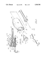
- FIG. 1 is a plan top view of the preferred embodiment of the apparatus of the present invention.
- FIG. 2 is a exploded, perspective view of the handle body portion of the preferred embodiment of the apparatus of the present invention
- FIG. 2A is a partial, sectional, elevational view of the preferred embodiment of the apparatus of the present invention illustrating the handle body, hook, and elastic member portions;
- FIG. 3 is a fragmentary, sectional, elevational view of the second embodiment of the apparatus of the present invention.
- FIG. 4 is a partial sectional elevation view of a third embodiment of the apparatus of the present invention.
- FIG. 5 is a sectional view taken along lines 5--5 of FIG. 4;
- FIG. 6 is a sectional view taken along lines 6--6 of FIG. 4;
- FIG. 7 is a partial elevational view of the third embodiment of the apparatus of the present invention.
- FIG. 8 is a sectional view taken along lines 8--8 of FIG. 4;
- FIG. 9 is a sectional view taken along lines 9--9 of FIG. 4;
- FIG. 10 is an enlarged fragmentary sectional view of the notch portion of the handle body of the third embodiment of the apparatus of the present invention.
- FIG. 11 is a side sectional view of the fourth embodiment of the apparatus of the present invention.
- FIG. 12 is an end view of the fourth embodiment of the apparatus of the present invention.
- FIG. 13 is a partial sectional elevational view of the fourth embodiment of the apparatus of the present invention.
- FIG. 14 is another partial sectional elevational view of the fourth embodiment of the apparatus of the present invention.
- FIG. 15 is a partial end view of the fourth embodiment of the apparatus of the present invention.
- FIG. 1 shows generally the preferred embodiment of the apparatus of the present invention designated generally by the numeral 10.
- retractor apparatus 10 includes a frame 11 having an open center 12.
- the frame 11 can have a circular or annular shape as shown. This allows an open center 12 to be placed in conformity with the surface of the patient's body and about a surgical site.
- Frame 11 has an annular flange 13 with a plurality of notches 14. Each notch 14 has a width 15.
- a plurality of retractor stays 16 can be placed about frame 11 as shown in FIG. 1.
- Each stay 16 includes an elongated elastic member 18.
- Elastic member 18 is preferably a length of either hollow elastic tubing or solid elastic material that fits a notch 14 at the proximal 19 end of the length of elastic member 18.
- the diameter of each length of elastic tubing 18 is preferably thicker than the width 15 of each notch 14.
- Each retractor stay 16 includes a proximal end 19 that forms a connection with handle 20.
- Handle 20 carries at its distal end a hook 17 that is used to engage tissue to be retracted.
- Hook 17 can be of uniform diameter wire construction (preferably stainless steel or like surgical metallic material).
- FIGS. 2, 2A and 3 a first embodiment of the retractor stay is shown, designated as 10A in FIGS. 2 and 2A.
- handle body 20 has distal end 24 and proximal end 23.
- a first hollow bore 25 is provided through handle body 20, communicating with proximal end 23 and distal end 24.
- elastic member 18 is preferably an elongated length of hollow elastic tubing having a wall 21 and a full length central longitudinal open ended bore 22 that communicates with the end portions of the elastic member 18.
- First bore 25 has a smaller bore section 26 that is generally cylindrically shaped and preferably of a uniform diameter.
- a larger section 27 of first bore 25 is conically shaped, bounded by a conical wall 28.
- the large section 27 of first bore 25 is largest at distal 24 end of handle body 20.
- a second bore 29 extends through handle body 20, communicating with both proximal end 23 and distal end 24.
- the second bore 29 carries a hook member 17.
- Hook member 17 has a distal curved end 30, a middle section that includes a curved, off-set 31, and a pair of cylindrically shaped linear sections 40.
- a transversely extending proximal end 32 defines an anchor that cooperates with a transverse section 35 of second bore 29.
- Bore 29 corresponds generally to the shape of the middle and proximal ends of hook 17.
- Second bore 29 has an enlarged section 34 that receives the curved offset 31 of hook 17.
- Plug 33 fits enlarged section 27 of first bore 25 as shown in FIG. 2A.
- Plug 33 is preferably tapered, having a conical section 33B that corresponds in shape to the conical wall 28 of large bore section 27 of first bore 25.
- Annular grove 33A can receive the extreme distal end of elastic member 18 as shown in FIG. 2A.
- the elastic member 18 is first channelled through first bore 25 beginning at proximal end 23.
- the extreme distal end 21A of elastic member 18 is then positioned at the distal end 24 of handle body 20.
- Tapered conical portion 33B of plug 33 fits inside bore 22 of elastic member 18 at the distal 21A end thereof.
- the conical portion 33B of plug 33 dilates elastic member 18 at distal end 24 so that the plug 33 and distal end 21A of elastic member 18 fit enlarged section 27 of first bore 25 as shown in FIG. 2A.
- retractor stay 10B an alternate construction (second embodiment) of retractor stay is shown, designated as 10B.
- handle body 20 is similarly constructed to the embodiment of FIGS. 2 and 2A.
- retractor stay 10B has a hook 40 with a curved distal end 41 that fits bore 36.
- Bore 36 is comprised of a pair of off-set bore sections, including cylindrical distal section 37 and cylindrical proximal section 39.
- Transverse section 38 of bore 36 provides a flat surface 44 that receives hook proximal end 42 at its anchor 43 as shown in FIG. 3.
- the hook 40 has a predominant linear portion that extends between the distal hook end 41 and the anchor 43, as shown in FIG. 3.
- FIGS. 4-10 show a third embodiment of the retractor stay, designated as lOC in FIG. 7.
- handle body 45 has a proximal end 46 and a distal end 47.
- a first bore section 48 is cylindrically shaped, extending completely through the handle body 45 and communicating with proximal 46 and distal 47 ends of body 45 as shown in FIG. 4.
- First bore section 48 is generally cylindrically shaped.
- Second bore section 49 is also cylindrically shaped, but only extends about half way through the handle body 45 as shown in FIG. 4. Bore section 49 begins at distal end 47 of handle body 45 and terminates about half the distance between the proximal 46 and distal 47 ends of handle body 45.
- Notch 50 extends between the bore sections 48 and 49.
- a third bore 51 is a bore that has off-set sections.
- Bore 51 has a cylindrically shaped distal section 52, a cylindrically shaped proximal section 53, and a transverse section 54 that connects the distal 52 and proximal 53 sections.
- the cylindrically shaped sections 52 and 53 are off-set, having parallel central longitudinal axes.
- Stop 55 is defined by an inner end portion of the cylindrical bore section 53 as shown in FIG. 4.
- Notch 50 is defined by a pair of flat surfaces 56, 57 as shown in FIG. 10.
- the surfaces 56, 57 are flat surfaces that form an acute angle 59.
- a stop 58 defines the inner end portion of notch 50 as shown in FIG. 10.
- Hook 60 attaches to handle body 45 at bore 51.
- the hook 60 has a distal hook end portion 61, a curved off-set 62, and a proximal anchor portion 63 as shown in FIG. 7. During use, the user forces the proximal 63 end of hook 60 into the cylindrical bore section 52 until the anchor 63 registers at flat surface 55.
- FIGS. 11-15 show a fourth embodiment of the apparatus of the present invention designated generally by the numeral 10D in FIG. 11.
- FIGS. 13 and 14 show handle body 64 having proximal end 65 and distal end 66.
- a first bore 67 extends between proximal end 65 and distal end 66.
- the first bore 67 has three bore sections 67A, 67B, and 67C that form angles with each other as shown in FIG. 13.
- the first bore 67 receives elastic tubing member 18 as shown in FIG. 11.
- Second bore 68 has a first cylindrical section 68A and a second cylindrically shaped section 68B.
- a stop 69 extends laterally to define a narrowed diameter section 70 in between bore sections 68A and 68B as shown in FIGS. 11 and 13.
- a notch 71 is provided at distal 66 end of body 64, the notch being V-shaped to grasp elastic member 18 as shown in FIGS. 11 and 12 upon complete assembly.
- the second bore 68 receives hook member 72.
- the hook member 72 includes a curved portion 73, and offset 74 and a folded anchor 75 as shown in FIGS. 11 and 14.
- the user first inserts the extreme distal end of elastic member 18 into cylindrical sections 68A of bore 68 as shown in FIG. 13.
- the user ten routes the proximal end of elastic member 18 through the bore 67 beginning at the distal 66 end of body 64.
- the user then anchors the distal end of hook 72 at anchor 75 into the second bore 68 as shown in FIG. 11 so that the offset 74 clamps the distal end of elastic member 18 as shown in FIG. 11.
- the notch 71 also grips elastic tubing 18.
- the user then pulls on the proximal end of elastic member 18 until the elastic member 18 is fully engaged at notch 71 as shown in FIG. 11.
Abstract
Description
______________________________________ PARTS LIST Part Number Description ______________________________________ 10 retractor apparatus .sup. 10A retractor stay .sup. 10B retractor stay .sup. 10C retractor stay .sup. 10D retractor stay 11frame 12open center 13annular flange 14notch 15 width ofnotch 16 elastic retractor stay 17hook 18elastic member 19proximal end 20handle body 21 tubing wall .sup.21A tubing end 22hollow bore 23proximal end 24 distal end 25first bore 26smaller section 27larger section 28conical wall 29 second bore 30distal end 31curved section 32proximal end 33 plug 34enlarged section 35transverse section 36 bore 37 cylindricaldistal section 38transverse section 39 cylindricalproximal section 40linear section 41 hookdistal end 42proximal end 43anchor 44flat surface 45handle body 46proximal end 47distal end 48first bore section 49second bore section 50notch 51 bore 52cylindrical section 53cylindrical section 54transverse section 55flat surface 56flat surface 57flat surface 58flat surface 59angle 60hook 61distal end 62 bend 63anchor 64 handle body 65proximal end 66distal end 67 first bore .sup. 67A section .sup. 67B section .sup.67C section 68 second bore 69stop 70 narrowedsection 71notch 72hook 73 curveddistal end 74 offset 75 anchor ______________________________________
Claims (19)
Priority Applications (1)
| Application Number | Priority Date | Filing Date | Title |
|---|---|---|---|
| US08/671,405 US5769783A (en) | 1996-06-27 | 1996-06-27 | Surgical retractor stay apparatus |
Applications Claiming Priority (1)
| Application Number | Priority Date | Filing Date | Title |
|---|---|---|---|
| US08/671,405 US5769783A (en) | 1996-06-27 | 1996-06-27 | Surgical retractor stay apparatus |
Publications (1)
| Publication Number | Publication Date |
|---|---|
| US5769783A true US5769783A (en) | 1998-06-23 |
Family
ID=24694395
Family Applications (1)
| Application Number | Title | Priority Date | Filing Date |
|---|---|---|---|
| US08/671,405 Expired - Lifetime US5769783A (en) | 1996-06-27 | 1996-06-27 | Surgical retractor stay apparatus |
Country Status (1)
| Country | Link |
|---|---|
| US (1) | US5769783A (en) |
Cited By (76)
| Publication number | Priority date | Publication date | Assignee | Title |
|---|---|---|---|---|
| US5951467A (en) * | 1999-03-23 | 1999-09-14 | Applied Medical Technology, Inc. | Reconfigurable and self-retaining surgical retractor |
| US5964697A (en) * | 1996-04-22 | 1999-10-12 | Lone Star Medical Products, Inc. | Surgical retractor stay apparatus |
| US5964698A (en) * | 1999-01-20 | 1999-10-12 | Lone Star Medical Products, Inc. | Sliding hook assembly for use with a surgical retractor stay apparatus and methods for use |
| US6077221A (en) * | 1999-09-01 | 2000-06-20 | Lone Star Medical Products, Inc. | Surgical restraint system |
| US6090043A (en) * | 1999-05-17 | 2000-07-18 | Applied Medical Technology, Inc. | Tissue retractor retention band |
| US6117072A (en) * | 1998-12-28 | 2000-09-12 | Lone Star Medical Products, Inc. | Plastic stay assembly for use with MRI and X-ray imaging systems |
| US6190312B1 (en) | 1999-03-04 | 2001-02-20 | Lone Star Medical Products, Inc. | Variable geometry retractor and disposable retractor stay clips and method of use |
| US6468207B1 (en) | 2000-02-04 | 2002-10-22 | Lone Star Medical Products, Inc. | Deep tissue surgical retractor apparatus and method of retracting tissue |
| US6582364B2 (en) | 1999-10-14 | 2003-06-24 | Atropos Limited | Retractor and method for use |
| US6659945B2 (en) | 2001-06-29 | 2003-12-09 | Depuy Orthopaedics, Inc. | Self retaining retractor ring |
| US20040059194A1 (en) * | 2002-07-18 | 2004-03-25 | Minnesota Scientific, Inc. | Method and apparatus for replacing knee-joint |
| US20040186356A1 (en) * | 2001-08-08 | 2004-09-23 | O'malley Michael T. | Surgical retractor and tissue stabilization device |
| US20040215063A1 (en) * | 1993-09-06 | 2004-10-28 | Atropos Ltd. | Apparatus for use in surgery and a valve |
| US6846287B2 (en) | 1998-12-01 | 2005-01-25 | Atropos Limited | Surgical device for retracting and/or sealing an incision |
| US20050027171A1 (en) * | 2001-11-21 | 2005-02-03 | Minnesota Scientific, Inc. | Method for knee-joint surgery |
| US20050090717A1 (en) * | 1998-12-01 | 2005-04-28 | Frank Bonadio | Wound retractor device |
| US20050155611A1 (en) * | 2003-11-05 | 2005-07-21 | Trevor Vaugh | Surgical sealing device |
| US6932765B2 (en) | 2001-10-26 | 2005-08-23 | Minnesota Scientific, Inc. | Apparatus for retaining otherwise hand-held retractors |
| US20050197537A1 (en) * | 1998-12-01 | 2005-09-08 | Frank Bonadio | Wound retractor device |
| US20050203346A1 (en) * | 1999-10-14 | 2005-09-15 | Frank Bonadio | Wound retractor device |
| US20050272982A1 (en) * | 2001-10-26 | 2005-12-08 | Minnesota Scientific, Inc. | Apparatus for retaining otherwise hand-held retractors and method of use |
| US20060247498A1 (en) * | 1998-12-01 | 2006-11-02 | Frank Bonadio | Instrument access device |
| US20060272979A1 (en) * | 2005-06-07 | 2006-12-07 | Lubbers Lawrence M | Surgical Tray |
| US20070004968A1 (en) * | 1998-12-01 | 2007-01-04 | Frank Bonadio | Seal for a cannula |
| US20070093696A1 (en) * | 2001-11-21 | 2007-04-26 | The LeVahn Intellectual Property Holding Company, LLC | Method of table mounted retraction in hip surgery and surgical retractor |
| US20070118175A1 (en) * | 2002-08-08 | 2007-05-24 | John Butler | Device |
| US20070161866A1 (en) * | 2006-01-11 | 2007-07-12 | Lone Star Medical Products, Inc. | Deep tissue blade for use with retractor systems |
| US20070161867A1 (en) * | 2006-01-11 | 2007-07-12 | Lone Star Medical Products, Inc. | Retractor blade and bridge system |
| US20070238933A1 (en) * | 2006-04-11 | 2007-10-11 | Lone Star Medical Products, Inc. | Posterior approach retractor ring and attachments system |
| US20070260125A1 (en) * | 2006-05-02 | 2007-11-08 | Strauss Kevin R | Minimally open retraction device |
| JP2008178705A (en) * | 1999-05-17 | 2008-08-07 | Applied Medical Technology Inc | Tissue retractor retention band |
| US20080269564A1 (en) * | 2007-04-17 | 2008-10-30 | Coopersurgical, Incorporated | Surgical retractor system and method |
| US20100191253A1 (en) * | 2009-01-23 | 2010-07-29 | Oostman Jr Clifford A | Skin Tensioner for Hair Transplantation |
| US7867164B2 (en) | 1999-10-14 | 2011-01-11 | Atropos Limited | Wound retractor system |
| US20110178533A1 (en) * | 2010-01-15 | 2011-07-21 | Oostman Jr Clifford A | Tensioning Device and Method for Hair Transplantation |
| US8016755B2 (en) | 2000-10-19 | 2011-09-13 | Applied Medical Resources Corporation | Surgical access apparatus and method |
| US8021296B2 (en) | 1999-12-01 | 2011-09-20 | Atropos Limited | Wound retractor |
| WO2011149466A1 (en) * | 2010-05-27 | 2011-12-01 | Picha George J | Tissue retractor stay |
| US8109873B2 (en) | 2007-05-11 | 2012-02-07 | Applied Medical Resources Corporation | Surgical retractor with gel pad |
| US8157835B2 (en) | 2001-08-14 | 2012-04-17 | Applied Medical Resouces Corporation | Access sealing apparatus and method |
| US8187177B2 (en) | 2003-09-17 | 2012-05-29 | Applied Medical Resources Corporation | Surgical instrument access device |
| US8187178B2 (en) | 2007-06-05 | 2012-05-29 | Atropos Limited | Instrument access device |
| US8226552B2 (en) | 2007-05-11 | 2012-07-24 | Applied Medical Resources Corporation | Surgical retractor |
| US8235054B2 (en) | 2002-06-05 | 2012-08-07 | Applied Medical Resources Corporation | Wound retractor |
| US8262568B2 (en) | 2008-10-13 | 2012-09-11 | Applied Medical Resources Corporation | Single port access system |
| US8267858B2 (en) | 2005-10-14 | 2012-09-18 | Applied Medical Resources Corporation | Wound retractor with gel cap |
| US8343047B2 (en) | 2008-01-22 | 2013-01-01 | Applied Medical Resources Corporation | Surgical instrument access device |
| US8375955B2 (en) | 2009-02-06 | 2013-02-19 | Atropos Limited | Surgical procedure |
| US8388526B2 (en) | 2001-10-20 | 2013-03-05 | Applied Medical Resources Corporation | Wound retraction apparatus and method |
| US20130137934A1 (en) * | 2011-11-30 | 2013-05-30 | Abeon Medical Corporation | Tissue retractor stay |
| CN103519854A (en) * | 2013-10-18 | 2014-01-22 | 王云和 | Skin draw hook retractor fixing device for operations |
| US8657740B2 (en) | 2007-06-05 | 2014-02-25 | Atropos Limited | Instrument access device |
| US8703034B2 (en) | 2001-08-14 | 2014-04-22 | Applied Medical Resources Corporation | Method of making a tack-free gel |
| US8758236B2 (en) | 2011-05-10 | 2014-06-24 | Applied Medical Resources Corporation | Wound retractor |
| US8932214B2 (en) | 2003-02-25 | 2015-01-13 | Applied Medical Resources Corporation | Surgical access system |
| US9138218B2 (en) | 2010-05-27 | 2015-09-22 | Abeon Medical Corporation | Tissue retractor stay |
| US9289115B2 (en) | 2010-10-01 | 2016-03-22 | Applied Medical Resources Corporation | Natural orifice surgery system |
| US9289200B2 (en) | 2010-10-01 | 2016-03-22 | Applied Medical Resources Corporation | Natural orifice surgery system |
| US9351759B2 (en) | 2007-06-05 | 2016-05-31 | Atropos Limited | Instrument access device |
| US9392965B2 (en) | 2013-03-14 | 2016-07-19 | Restoration Robotics, Inc. | Method and apparatus for determining a change in tension of a body surface |
| US9408691B2 (en) | 2013-03-14 | 2016-08-09 | Restoration Robotics, Inc. | Locator device for medical procedures on the body surface and method of its use |
| US9510913B2 (en) | 2012-09-12 | 2016-12-06 | Restoration Robotics, Inc. | Skin tensioning devices and methods of their use |
| US9642608B2 (en) | 2014-07-18 | 2017-05-09 | Applied Medical Resources Corporation | Gels having permanent tack free coatings and method of manufacture |
| US9951904B2 (en) | 2015-03-24 | 2018-04-24 | Stryker Corporation | Rotatable seat clamps for rail clamp |
| US9949730B2 (en) | 2014-11-25 | 2018-04-24 | Applied Medical Resources Corporation | Circumferential wound retraction with support and guidance structures |
| US10149674B2 (en) | 2015-08-12 | 2018-12-11 | K2M, Inc. | Orthopedic surgical system including surgical access systems, distraction systems, and methods of using same |
| US10172641B2 (en) | 2014-08-15 | 2019-01-08 | Applied Medical Resources Corporation | Natural orifice surgery system |
| US10307151B2 (en) * | 2015-08-19 | 2019-06-04 | Wecan Medicare Co., Ltd. | Retractor for surgical operation |
| US10368908B2 (en) | 2015-09-15 | 2019-08-06 | Applied Medical Resources Corporation | Surgical robotic access system |
| WO2019200330A1 (en) * | 2018-04-12 | 2019-10-17 | Dignity Health | Table mounted retractor system |
| US10478364B2 (en) | 2014-03-10 | 2019-11-19 | Stryker Corporation | Limb positioning system |
| US10499894B2 (en) | 2015-08-12 | 2019-12-10 | K2M, Inc. | Orthopedic surgical system including surgical access systems, distraction systems, and methods of using same |
| US10575840B2 (en) | 2015-10-07 | 2020-03-03 | Applied Medical Resources Corporation | Wound retractor with multi-segment outer ring |
| US10674896B2 (en) | 2016-09-12 | 2020-06-09 | Applied Medical Resources Corporation | Surgical robotic access system for irregularly shaped robotic actuators and associated robotic surgical instruments |
| US11425870B1 (en) * | 2018-09-06 | 2022-08-30 | Clifford A. Goudey | Macroalgae farming including attaching seaweed to a line |
| US11471142B2 (en) | 2013-03-15 | 2022-10-18 | Applied Medical Resources Corporation | Mechanical gel surgical access device |
Citations (25)
| Publication number | Priority date | Publication date | Assignee | Title |
|---|---|---|---|---|
| US170573A (en) * | 1875-11-30 | Improvement in bed-clothes holders | ||
| US334711A (en) * | 1886-01-19 | Eobeet loeenz | ||
| US3515129A (en) * | 1967-12-29 | 1970-06-02 | Andrew Truhan | Surgical retractor and retainer device for sutures |
| GB1222141A (en) * | 1968-06-20 | 1971-02-10 | Hideo Yamamoto | Circular surgical retractor apparatus |
| US3762401A (en) * | 1972-01-05 | 1973-10-02 | J Tupper | Surgical retractor |
| US3916879A (en) * | 1974-03-12 | 1975-11-04 | Bennett D Cotten | Cotton roll holder and lip retractor |
| GB1550254A (en) * | 1977-02-01 | 1979-08-15 | Yamamoto H | Surgical retractor |
| US4185636A (en) * | 1977-12-29 | 1980-01-29 | Albert Einstein College Of Medicine Of Yeshiva University | Suture organizer, prosthetic device holder, and related surgical procedures |
| US4254763A (en) * | 1979-06-07 | 1981-03-10 | Codman & Shurtleff, Inc. | Surgical retractor assembly |
| US4257406A (en) * | 1979-05-18 | 1981-03-24 | Schenk Alan G | Iris retractor and pupil dilator |
| US4263900A (en) * | 1979-04-20 | 1981-04-28 | Codman And Shurtleff, Inc. | Pressure-responsive surgical tool assembly |
| US4274398A (en) * | 1979-05-14 | 1981-06-23 | Scott Jr Frank B | Surgical retractor utilizing elastic tubes frictionally held in spaced notches |
| US4321916A (en) * | 1980-03-26 | 1982-03-30 | Mckee Douglas C | Eyelid retractor |
| US4337763A (en) * | 1980-04-21 | 1982-07-06 | The United States Of America As Represented By The Department Of Health, Education And Welfare | Illuminated surgical instrument |
| US4337762A (en) * | 1980-02-19 | 1982-07-06 | Gauthier William K | Surgical retractor |
| US4344420A (en) * | 1980-05-02 | 1982-08-17 | Forder William C F | Surgical retractor |
| US4355631A (en) * | 1981-03-19 | 1982-10-26 | Minnesota Scientific, Inc. | Surgical retractor apparatus with improved clamping device |
| US4380999A (en) * | 1980-07-15 | 1983-04-26 | Healy Keelin E | Stepped surgical retractor |
| US4387706A (en) * | 1981-04-10 | 1983-06-14 | Glass Robert M | Iris retractor |
| US4412532A (en) * | 1981-12-21 | 1983-11-01 | Anthony Richard R | Eyelash retractor |
| US4421108A (en) * | 1981-07-27 | 1983-12-20 | Codman & Shurtleff, Inc. | Surgical retractor holder |
| US4421107A (en) * | 1980-10-15 | 1983-12-20 | Estes Roger Q | Surgical retractor elements and assembly |
| US4430991A (en) * | 1981-11-05 | 1984-02-14 | Humboldt Products Corp. | Surgical retractor stay device and tube connector |
| US4434791A (en) * | 1982-03-15 | 1984-03-06 | Humboldt Products Corp. | Surgical retractor array system |
| US4559677A (en) * | 1984-05-31 | 1985-12-24 | Tracy Richard J | Stretchable tie-down device |
-
1996
- 1996-06-27 US US08/671,405 patent/US5769783A/en not_active Expired - Lifetime
Patent Citations (26)
| Publication number | Priority date | Publication date | Assignee | Title |
|---|---|---|---|---|
| US334711A (en) * | 1886-01-19 | Eobeet loeenz | ||
| US170573A (en) * | 1875-11-30 | Improvement in bed-clothes holders | ||
| US3515129A (en) * | 1967-12-29 | 1970-06-02 | Andrew Truhan | Surgical retractor and retainer device for sutures |
| GB1222141A (en) * | 1968-06-20 | 1971-02-10 | Hideo Yamamoto | Circular surgical retractor apparatus |
| US3762401A (en) * | 1972-01-05 | 1973-10-02 | J Tupper | Surgical retractor |
| US3916879A (en) * | 1974-03-12 | 1975-11-04 | Bennett D Cotten | Cotton roll holder and lip retractor |
| GB1550254A (en) * | 1977-02-01 | 1979-08-15 | Yamamoto H | Surgical retractor |
| GB1550255A (en) * | 1977-02-01 | 1979-08-15 | Yamamoto H | Retraction element for a surgical retractor |
| US4185636A (en) * | 1977-12-29 | 1980-01-29 | Albert Einstein College Of Medicine Of Yeshiva University | Suture organizer, prosthetic device holder, and related surgical procedures |
| US4263900A (en) * | 1979-04-20 | 1981-04-28 | Codman And Shurtleff, Inc. | Pressure-responsive surgical tool assembly |
| US4274398A (en) * | 1979-05-14 | 1981-06-23 | Scott Jr Frank B | Surgical retractor utilizing elastic tubes frictionally held in spaced notches |
| US4257406A (en) * | 1979-05-18 | 1981-03-24 | Schenk Alan G | Iris retractor and pupil dilator |
| US4254763A (en) * | 1979-06-07 | 1981-03-10 | Codman & Shurtleff, Inc. | Surgical retractor assembly |
| US4337762A (en) * | 1980-02-19 | 1982-07-06 | Gauthier William K | Surgical retractor |
| US4321916A (en) * | 1980-03-26 | 1982-03-30 | Mckee Douglas C | Eyelid retractor |
| US4337763A (en) * | 1980-04-21 | 1982-07-06 | The United States Of America As Represented By The Department Of Health, Education And Welfare | Illuminated surgical instrument |
| US4344420A (en) * | 1980-05-02 | 1982-08-17 | Forder William C F | Surgical retractor |
| US4380999A (en) * | 1980-07-15 | 1983-04-26 | Healy Keelin E | Stepped surgical retractor |
| US4421107A (en) * | 1980-10-15 | 1983-12-20 | Estes Roger Q | Surgical retractor elements and assembly |
| US4355631A (en) * | 1981-03-19 | 1982-10-26 | Minnesota Scientific, Inc. | Surgical retractor apparatus with improved clamping device |
| US4387706A (en) * | 1981-04-10 | 1983-06-14 | Glass Robert M | Iris retractor |
| US4421108A (en) * | 1981-07-27 | 1983-12-20 | Codman & Shurtleff, Inc. | Surgical retractor holder |
| US4430991A (en) * | 1981-11-05 | 1984-02-14 | Humboldt Products Corp. | Surgical retractor stay device and tube connector |
| US4412532A (en) * | 1981-12-21 | 1983-11-01 | Anthony Richard R | Eyelash retractor |
| US4434791A (en) * | 1982-03-15 | 1984-03-06 | Humboldt Products Corp. | Surgical retractor array system |
| US4559677A (en) * | 1984-05-31 | 1985-12-24 | Tracy Richard J | Stretchable tie-down device |
Non-Patent Citations (6)
| Title |
|---|
| Accurate Surgical & Scientific Instruments Corporation Brochure (No Date). * |
| Bone Retractors and Retractors AESCULAP , Product catalog p. 319 (No Date). * |
| Bone Retractors and Retractors AESCULAP©, Product catalog p. 319 (No Date). |
| I.S.I. North America, Inc. International Surgical Instruments Brochure (No Date). * |
| Thermoplastic Replaces Metal in Disposable Abdominal Retractor , MD&M Review, ULTOP Conveyor Modules (No Date). * |
| Thermoplastic Replaces Metal in Disposable Abdominal Retractor, MD&M Review, ULTOP® Conveyor Modules (No Date). |
Cited By (157)
| Publication number | Priority date | Publication date | Assignee | Title |
|---|---|---|---|---|
| US8752553B2 (en) | 1993-09-06 | 2014-06-17 | Atropos Limited | Apparatus for use in surgery and a valve |
| US20040215063A1 (en) * | 1993-09-06 | 2004-10-28 | Atropos Ltd. | Apparatus for use in surgery and a valve |
| US5964697A (en) * | 1996-04-22 | 1999-10-12 | Lone Star Medical Products, Inc. | Surgical retractor stay apparatus |
| US6846287B2 (en) | 1998-12-01 | 2005-01-25 | Atropos Limited | Surgical device for retracting and/or sealing an incision |
| US10278688B2 (en) | 1998-12-01 | 2019-05-07 | Atropos Limited | Wound retractor device |
| US9095300B2 (en) | 1998-12-01 | 2015-08-04 | Atropos Limited | Wound retractor device |
| US8317691B2 (en) | 1998-12-01 | 2012-11-27 | Atropos Limited | Wound retractor device |
| US7081089B2 (en) | 1998-12-01 | 2006-07-25 | Atropos Limited | Surgical device for retracting and/or sealing an incision |
| US8734336B2 (en) | 1998-12-01 | 2014-05-27 | Atropos Limited | Wound retractor device |
| US7998068B2 (en) | 1998-12-01 | 2011-08-16 | Atropos Limited | Instrument access device |
| US8888693B2 (en) | 1998-12-01 | 2014-11-18 | Atropos Limited | Instrument access device |
| US20070004968A1 (en) * | 1998-12-01 | 2007-01-04 | Frank Bonadio | Seal for a cannula |
| US7537564B2 (en) | 1998-12-01 | 2009-05-26 | Atropos Limited | Wound retractor device |
| US20060247498A1 (en) * | 1998-12-01 | 2006-11-02 | Frank Bonadio | Instrument access device |
| US9700296B2 (en) | 1998-12-01 | 2017-07-11 | Atropos Limited | Wound retractor device |
| US20050197537A1 (en) * | 1998-12-01 | 2005-09-08 | Frank Bonadio | Wound retractor device |
| US9757110B2 (en) | 1998-12-01 | 2017-09-12 | Atropos Limited | Instrument access device |
| US20050090717A1 (en) * | 1998-12-01 | 2005-04-28 | Frank Bonadio | Wound retractor device |
| US20050090716A1 (en) * | 1998-12-01 | 2005-04-28 | Atropos Limited | Surgical device for retracting and/or sealing an incision |
| US6117072A (en) * | 1998-12-28 | 2000-09-12 | Lone Star Medical Products, Inc. | Plastic stay assembly for use with MRI and X-ray imaging systems |
| US5964698A (en) * | 1999-01-20 | 1999-10-12 | Lone Star Medical Products, Inc. | Sliding hook assembly for use with a surgical retractor stay apparatus and methods for use |
| US6190312B1 (en) | 1999-03-04 | 2001-02-20 | Lone Star Medical Products, Inc. | Variable geometry retractor and disposable retractor stay clips and method of use |
| US5951467A (en) * | 1999-03-23 | 1999-09-14 | Applied Medical Technology, Inc. | Reconfigurable and self-retaining surgical retractor |
| JP2008178705A (en) * | 1999-05-17 | 2008-08-07 | Applied Medical Technology Inc | Tissue retractor retention band |
| US6090043A (en) * | 1999-05-17 | 2000-07-18 | Applied Medical Technology, Inc. | Tissue retractor retention band |
| WO2000069326A1 (en) * | 1999-05-17 | 2000-11-23 | Applied Medical Technology, Inc. | Tissue retractor retention band |
| US6077221A (en) * | 1999-09-01 | 2000-06-20 | Lone Star Medical Products, Inc. | Surgical restraint system |
| US7445597B2 (en) | 1999-10-14 | 2008-11-04 | Atropos Limited | Retractor |
| US20050203346A1 (en) * | 1999-10-14 | 2005-09-15 | Frank Bonadio | Wound retractor device |
| US8986202B2 (en) | 1999-10-14 | 2015-03-24 | Atropos Limited | Retractor |
| US6582364B2 (en) | 1999-10-14 | 2003-06-24 | Atropos Limited | Retractor and method for use |
| US8740785B2 (en) | 1999-10-14 | 2014-06-03 | Atropos Limited | Wound retractor system |
| US20040049100A1 (en) * | 1999-10-14 | 2004-03-11 | Atropos Limited | Retractor |
| US7867164B2 (en) | 1999-10-14 | 2011-01-11 | Atropos Limited | Wound retractor system |
| US9277908B2 (en) | 1999-10-14 | 2016-03-08 | Atropos Limited | Retractor |
| US8021296B2 (en) | 1999-12-01 | 2011-09-20 | Atropos Limited | Wound retractor |
| US8657741B2 (en) | 1999-12-01 | 2014-02-25 | Atropos Limited | Wound retractor |
| US6468207B1 (en) | 2000-02-04 | 2002-10-22 | Lone Star Medical Products, Inc. | Deep tissue surgical retractor apparatus and method of retracting tissue |
| US8496581B2 (en) | 2000-10-19 | 2013-07-30 | Applied Medical Resources Corporation | Surgical access apparatus and method |
| US8911366B2 (en) | 2000-10-19 | 2014-12-16 | Applied Medical Resources Corporation | Surgical access apparatus and method |
| US8105234B2 (en) | 2000-10-19 | 2012-01-31 | Applied Medical Resources Corporation | Surgical access apparatus and method |
| US8672839B2 (en) | 2000-10-19 | 2014-03-18 | Applied Medical Resource Corporation | Surgical access apparatus and method |
| US8070676B2 (en) | 2000-10-19 | 2011-12-06 | Applied Medical Resources Corporation | Surgical access apparatus and method |
| US8016755B2 (en) | 2000-10-19 | 2011-09-13 | Applied Medical Resources Corporation | Surgical access apparatus and method |
| US6659945B2 (en) | 2001-06-29 | 2003-12-09 | Depuy Orthopaedics, Inc. | Self retaining retractor ring |
| US20040186356A1 (en) * | 2001-08-08 | 2004-09-23 | O'malley Michael T. | Surgical retractor and tissue stabilization device |
| US8703034B2 (en) | 2001-08-14 | 2014-04-22 | Applied Medical Resources Corporation | Method of making a tack-free gel |
| US9878140B2 (en) | 2001-08-14 | 2018-01-30 | Applied Medical Resources Corporation | Access sealing apparatus and method |
| US8870904B2 (en) | 2001-08-14 | 2014-10-28 | Applied Medical Resources Corporation | Access sealing apparatus and method |
| US8157835B2 (en) | 2001-08-14 | 2012-04-17 | Applied Medical Resouces Corporation | Access sealing apparatus and method |
| US9669153B2 (en) | 2001-08-14 | 2017-06-06 | Applied Medical Resources Corporation | Method of manufacturing a tack-free gel for a surgical device |
| US8388526B2 (en) | 2001-10-20 | 2013-03-05 | Applied Medical Resources Corporation | Wound retraction apparatus and method |
| US6932765B2 (en) | 2001-10-26 | 2005-08-23 | Minnesota Scientific, Inc. | Apparatus for retaining otherwise hand-held retractors |
| US7309312B2 (en) | 2001-10-26 | 2007-12-18 | Minnesota Scientific, Inc. | Apparatus for retaining otherwise hand-held retractors and method of use |
| US20050272982A1 (en) * | 2001-10-26 | 2005-12-08 | Minnesota Scientific, Inc. | Apparatus for retaining otherwise hand-held retractors and method of use |
| US20050187435A1 (en) * | 2001-10-26 | 2005-08-25 | Minnesota Scientific, Inc. | Apparatus for retaining otherwise hand-held retractors |
| US7458933B2 (en) * | 2001-11-21 | 2008-12-02 | Minnesota Scientific, Inc. | Method for knee-joint surgery |
| US20050027171A1 (en) * | 2001-11-21 | 2005-02-03 | Minnesota Scientific, Inc. | Method for knee-joint surgery |
| US20070093696A1 (en) * | 2001-11-21 | 2007-04-26 | The LeVahn Intellectual Property Holding Company, LLC | Method of table mounted retraction in hip surgery and surgical retractor |
| US8973583B2 (en) | 2002-06-05 | 2015-03-10 | Applied Medical Resources Corporation | Wound retractor |
| US8235054B2 (en) | 2002-06-05 | 2012-08-07 | Applied Medical Resources Corporation | Wound retractor |
| US9561024B2 (en) | 2002-06-05 | 2017-02-07 | Applied Medical Resources Corporation | Wound retractor |
| US10507017B2 (en) | 2002-06-05 | 2019-12-17 | Applied Medical Resources Corporation | Wound retractor |
| US20040059194A1 (en) * | 2002-07-18 | 2004-03-25 | Minnesota Scientific, Inc. | Method and apparatus for replacing knee-joint |
| US9737335B2 (en) | 2002-08-08 | 2017-08-22 | Atropos Limited | Device |
| US10405883B2 (en) | 2002-08-08 | 2019-09-10 | Atropos Limited | Surgical device |
| US20070118175A1 (en) * | 2002-08-08 | 2007-05-24 | John Butler | Device |
| US9271753B2 (en) | 2002-08-08 | 2016-03-01 | Atropos Limited | Surgical device |
| US9307976B2 (en) | 2002-10-04 | 2016-04-12 | Atropos Limited | Wound retractor |
| US8932214B2 (en) | 2003-02-25 | 2015-01-13 | Applied Medical Resources Corporation | Surgical access system |
| US9295459B2 (en) | 2003-02-25 | 2016-03-29 | Applied Medical Resources Corporation | Surgical access system |
| US8187177B2 (en) | 2003-09-17 | 2012-05-29 | Applied Medical Resources Corporation | Surgical instrument access device |
| US8357086B2 (en) | 2003-09-17 | 2013-01-22 | Applied Medical Resources Corporation | Surgical instrument access device |
| US20050155611A1 (en) * | 2003-11-05 | 2005-07-21 | Trevor Vaugh | Surgical sealing device |
| US20060272979A1 (en) * | 2005-06-07 | 2006-12-07 | Lubbers Lawrence M | Surgical Tray |
| US8308639B2 (en) | 2005-10-14 | 2012-11-13 | Applied Medical Resources Corporation | Split hoop wound retractor with gel pad |
| US9474519B2 (en) | 2005-10-14 | 2016-10-25 | Applied Medical Resources Corporation | Hand access laparoscopic device |
| US8647265B2 (en) | 2005-10-14 | 2014-02-11 | Applied Medical Resources Corporation | Hand access laparoscopic device |
| US9101354B2 (en) | 2005-10-14 | 2015-08-11 | Applied Medical Resources Corporation | Wound retractor with gel cap |
| US8267858B2 (en) | 2005-10-14 | 2012-09-18 | Applied Medical Resources Corporation | Wound retractor with gel cap |
| US9017254B2 (en) | 2005-10-14 | 2015-04-28 | Applied Medical Resources Corporation | Hand access laparoscopic device |
| US8313431B2 (en) | 2005-10-14 | 2012-11-20 | Applied Medical Resources Corporation | Split hoop wound retractor |
| US9649102B2 (en) | 2005-10-14 | 2017-05-16 | Applied Medical Resources Corporation | Wound retractor with split hoops |
| US8414487B2 (en) | 2005-10-14 | 2013-04-09 | Applied Medical Resources Corporation | Circular surgical retractor |
| US20070161867A1 (en) * | 2006-01-11 | 2007-07-12 | Lone Star Medical Products, Inc. | Retractor blade and bridge system |
| US20070161866A1 (en) * | 2006-01-11 | 2007-07-12 | Lone Star Medical Products, Inc. | Deep tissue blade for use with retractor systems |
| US20070238933A1 (en) * | 2006-04-11 | 2007-10-11 | Lone Star Medical Products, Inc. | Posterior approach retractor ring and attachments system |
| US9131934B2 (en) | 2006-05-02 | 2015-09-15 | K2M, Inc. | Minimally open retraction device |
| US20070260125A1 (en) * | 2006-05-02 | 2007-11-08 | Strauss Kevin R | Minimally open retraction device |
| US11529132B2 (en) | 2006-05-02 | 2022-12-20 | K2M, Inc. | Minimally open retraction device |
| US8696560B2 (en) * | 2006-05-02 | 2014-04-15 | K2M, Inc. | Minimally open retraction device |
| US9681863B2 (en) | 2006-05-02 | 2017-06-20 | K2M, Inc. | Minimally open retraction device |
| US10485529B2 (en) | 2006-05-02 | 2019-11-26 | K2M, Inc. | Minimally open retraction device |
| US20080269564A1 (en) * | 2007-04-17 | 2008-10-30 | Coopersurgical, Incorporated | Surgical retractor system and method |
| US8961410B2 (en) | 2007-05-11 | 2015-02-24 | Applied Medical Resources Corporation | Surgical retractor with gel pad |
| US8109873B2 (en) | 2007-05-11 | 2012-02-07 | Applied Medical Resources Corporation | Surgical retractor with gel pad |
| US8226552B2 (en) | 2007-05-11 | 2012-07-24 | Applied Medical Resources Corporation | Surgical retractor |
| US8187178B2 (en) | 2007-06-05 | 2012-05-29 | Atropos Limited | Instrument access device |
| US9351759B2 (en) | 2007-06-05 | 2016-05-31 | Atropos Limited | Instrument access device |
| US10537360B2 (en) | 2007-06-05 | 2020-01-21 | Atropos Limited | Instrument access device |
| US9408597B2 (en) | 2007-06-05 | 2016-08-09 | Atropos Limited | Instrument access device |
| US8657740B2 (en) | 2007-06-05 | 2014-02-25 | Atropos Limited | Instrument access device |
| US10321934B2 (en) | 2007-06-05 | 2019-06-18 | Atropos Limited | Instrument access device |
| US8343047B2 (en) | 2008-01-22 | 2013-01-01 | Applied Medical Resources Corporation | Surgical instrument access device |
| US8721537B2 (en) | 2008-10-13 | 2014-05-13 | Applied Medical Resources Corporation | Single port access system |
| US8262568B2 (en) | 2008-10-13 | 2012-09-11 | Applied Medical Resources Corporation | Single port access system |
| US8894571B2 (en) | 2008-10-13 | 2014-11-25 | Applied Medical Resources Corporation | Single port access system |
| US8480575B2 (en) | 2008-10-13 | 2013-07-09 | Applied Medical Resources Corporation | Single port access system |
| US8388631B2 (en) | 2009-01-23 | 2013-03-05 | Restoration Robotics, Inc. | Skin tensioner for hair transplantation |
| US9597098B2 (en) | 2009-01-23 | 2017-03-21 | Restoration Robotics, Inc. | Skin tensioner for hair transplantation |
| US20100191253A1 (en) * | 2009-01-23 | 2010-07-29 | Oostman Jr Clifford A | Skin Tensioner for Hair Transplantation |
| US8375955B2 (en) | 2009-02-06 | 2013-02-19 | Atropos Limited | Surgical procedure |
| US20110178533A1 (en) * | 2010-01-15 | 2011-07-21 | Oostman Jr Clifford A | Tensioning Device and Method for Hair Transplantation |
| US8465498B2 (en) | 2010-01-15 | 2013-06-18 | Restoration Robotics, Inc. | Tensioning device and method for hair transplantation |
| EP2575635A4 (en) * | 2010-05-27 | 2015-04-22 | George J Picha | Tissue retractor stay |
| US9138218B2 (en) | 2010-05-27 | 2015-09-22 | Abeon Medical Corporation | Tissue retractor stay |
| EP2575635A1 (en) * | 2010-05-27 | 2013-04-10 | George J. Picha | Tissue retractor stay |
| WO2011149466A1 (en) * | 2010-05-27 | 2011-12-01 | Picha George J | Tissue retractor stay |
| US10376282B2 (en) | 2010-10-01 | 2019-08-13 | Applied Medical Resources Corporation | Natural orifice surgery system |
| US10271875B2 (en) | 2010-10-01 | 2019-04-30 | Applied Medical Resources Corporation | Natural orifice surgery system |
| US11123102B2 (en) | 2010-10-01 | 2021-09-21 | Applied Medical Resources Corporation | Natural orifice surgery system |
| US9872702B2 (en) | 2010-10-01 | 2018-01-23 | Applied Medical Resources Corporation | Natural orifice surgery system |
| US9289115B2 (en) | 2010-10-01 | 2016-03-22 | Applied Medical Resources Corporation | Natural orifice surgery system |
| US9289200B2 (en) | 2010-10-01 | 2016-03-22 | Applied Medical Resources Corporation | Natural orifice surgery system |
| US9192366B2 (en) | 2011-05-10 | 2015-11-24 | Applied Medical Resources Corporation | Wound retractor |
| US9241697B2 (en) | 2011-05-10 | 2016-01-26 | Applied Medical Resources Corporation | Wound retractor |
| US9307975B2 (en) | 2011-05-10 | 2016-04-12 | Applied Medical Resources Corporation | Wound retractor |
| US8758236B2 (en) | 2011-05-10 | 2014-06-24 | Applied Medical Resources Corporation | Wound retractor |
| US9011325B2 (en) * | 2011-11-30 | 2015-04-21 | Abeon Medical Corporation | Tissue retractor stay |
| WO2013082351A1 (en) * | 2011-11-30 | 2013-06-06 | Abeon Medical Corporation | Tissue retractor stay |
| US20130137934A1 (en) * | 2011-11-30 | 2013-05-30 | Abeon Medical Corporation | Tissue retractor stay |
| US9510913B2 (en) | 2012-09-12 | 2016-12-06 | Restoration Robotics, Inc. | Skin tensioning devices and methods of their use |
| US10028802B2 (en) | 2013-03-14 | 2018-07-24 | Restoration Robotics, Inc. | Locator device for medical procedures on the body surface and method of its use |
| US9392965B2 (en) | 2013-03-14 | 2016-07-19 | Restoration Robotics, Inc. | Method and apparatus for determining a change in tension of a body surface |
| US9408691B2 (en) | 2013-03-14 | 2016-08-09 | Restoration Robotics, Inc. | Locator device for medical procedures on the body surface and method of its use |
| US11471142B2 (en) | 2013-03-15 | 2022-10-18 | Applied Medical Resources Corporation | Mechanical gel surgical access device |
| CN103519854A (en) * | 2013-10-18 | 2014-01-22 | 王云和 | Skin draw hook retractor fixing device for operations |
| US10478364B2 (en) | 2014-03-10 | 2019-11-19 | Stryker Corporation | Limb positioning system |
| US9642608B2 (en) | 2014-07-18 | 2017-05-09 | Applied Medical Resources Corporation | Gels having permanent tack free coatings and method of manufacture |
| US10172641B2 (en) | 2014-08-15 | 2019-01-08 | Applied Medical Resources Corporation | Natural orifice surgery system |
| US11583316B2 (en) | 2014-08-15 | 2023-02-21 | Applied Medical Resources Corporation | Natural orifice surgery system |
| US10952768B2 (en) | 2014-08-15 | 2021-03-23 | Applied Medical Resources Corporation | Natural orifice surgery system |
| US9949730B2 (en) | 2014-11-25 | 2018-04-24 | Applied Medical Resources Corporation | Circumferential wound retraction with support and guidance structures |
| US9951904B2 (en) | 2015-03-24 | 2018-04-24 | Stryker Corporation | Rotatable seat clamps for rail clamp |
| US10499894B2 (en) | 2015-08-12 | 2019-12-10 | K2M, Inc. | Orthopedic surgical system including surgical access systems, distraction systems, and methods of using same |
| US11006942B2 (en) | 2015-08-12 | 2021-05-18 | K2M, Inc. | Orthopedic surgical system including surgical access systems, distraction systems, and methods of using same |
| US10149674B2 (en) | 2015-08-12 | 2018-12-11 | K2M, Inc. | Orthopedic surgical system including surgical access systems, distraction systems, and methods of using same |
| US10307151B2 (en) * | 2015-08-19 | 2019-06-04 | Wecan Medicare Co., Ltd. | Retractor for surgical operation |
| US11382658B2 (en) | 2015-09-15 | 2022-07-12 | Applied Medical Resources Corporation | Surgical robotic access system |
| US10368908B2 (en) | 2015-09-15 | 2019-08-06 | Applied Medical Resources Corporation | Surgical robotic access system |
| US11883068B2 (en) | 2015-09-15 | 2024-01-30 | Applied Medical Resources Corporation | Surgical robotic access system |
| US10575840B2 (en) | 2015-10-07 | 2020-03-03 | Applied Medical Resources Corporation | Wound retractor with multi-segment outer ring |
| US11602338B2 (en) | 2015-10-07 | 2023-03-14 | Applied Medical Resources Corporation | Wound retractor with multi-segment outer ring |
| US10674896B2 (en) | 2016-09-12 | 2020-06-09 | Applied Medical Resources Corporation | Surgical robotic access system for irregularly shaped robotic actuators and associated robotic surgical instruments |
| US11627867B2 (en) | 2016-09-12 | 2023-04-18 | Applied Medical Resources Corporation | Surgical robotic access system for irregularly shaped robotic actuators and associated robotic surgical instruments |
| WO2019200330A1 (en) * | 2018-04-12 | 2019-10-17 | Dignity Health | Table mounted retractor system |
| US11425870B1 (en) * | 2018-09-06 | 2022-08-30 | Clifford A. Goudey | Macroalgae farming including attaching seaweed to a line |
Similar Documents
| Publication | Publication Date | Title |
|---|---|---|
| US5769783A (en) | Surgical retractor stay apparatus | |
| US5964697A (en) | Surgical retractor stay apparatus | |
| US5785649A (en) | Surgical retractor stay apparatus | |
| US5964698A (en) | Sliding hook assembly for use with a surgical retractor stay apparatus and methods for use | |
| US6190312B1 (en) | Variable geometry retractor and disposable retractor stay clips and method of use | |
| US5176128A (en) | Organ retractor | |
| US6187000B1 (en) | Cannula for receiving surgical instruments | |
| US6652553B2 (en) | Surgical tool for use in expanding a cannula | |
| US7641670B2 (en) | Cannula for receiving surgical instruments | |
| US5899853A (en) | Double grip surgical retractor stay | |
| US5817107A (en) | Grasping instrument with a guided-on, attachable modified knot pusher | |
| US6471644B1 (en) | Endoscopic stabilization device and method of use | |
| US6562048B1 (en) | Deformable conduits and methods for shunting bodily fluid during surgery | |
| US20070238933A1 (en) | Posterior approach retractor ring and attachments system | |
| US6638265B1 (en) | Laparoscopy cannula adapter and assembly | |
| US6527793B1 (en) | Laparoscopic needle introducer device | |
| JPH0721004U (en) | Thoracic trocar |
Legal Events
| Date | Code | Title | Description |
|---|---|---|---|
| AS | Assignment |
Owner name: LONE STAR MEDICAL PRODUCTS, INC., TEXAS Free format text: ASSIGNMENT OF ASSIGNORS INTEREST;ASSIGNOR:FOWLER, JAMES M. JR.;REEL/FRAME:008057/0554 Effective date: 19960626 |
|
| STCF | Information on status: patent grant |
Free format text: PATENTED CASE |
|
| REMI | Maintenance fee reminder mailed | ||
| FPAY | Fee payment |
Year of fee payment: 4 |
|
| SULP | Surcharge for late payment | ||
| FPAY | Fee payment |
Year of fee payment: 8 |
|
| AS | Assignment |
Owner name: COOPERSURGICAL, INC., CONNECTICUT Free format text: MERGER;ASSIGNOR:LONE STAR MEDICAL PRODUCTS, INC.;REEL/FRAME:020125/0185 Effective date: 20071024 |
|
| FEPP | Fee payment procedure |
Free format text: PAT HOLDER NO LONGER CLAIMS SMALL ENTITY STATUS, ENTITY STATUS SET TO UNDISCOUNTED (ORIGINAL EVENT CODE: STOL); ENTITY STATUS OF PATENT OWNER: LARGE ENTITY |
|
| FPAY | Fee payment |
Year of fee payment: 12 |