US5771722A - Dual control mode lock system - Google Patents
Dual control mode lock system Download PDFInfo
- Publication number
- US5771722A US5771722A US08/483,277 US48327795A US5771722A US 5771722 A US5771722 A US 5771722A US 48327795 A US48327795 A US 48327795A US 5771722 A US5771722 A US 5771722A
- Authority
- US
- United States
- Prior art keywords
- key
- lock
- plug
- command signal
- keyway
- Prior art date
- Legal status (The legal status is an assumption and is not a legal conclusion. Google has not performed a legal analysis and makes no representation as to the accuracy of the status listed.)
- Expired - Fee Related
Links
- 230000009977 dual effect Effects 0.000 title description 2
- 230000008054 signal transmission Effects 0.000 claims abstract description 7
- 238000003780 insertion Methods 0.000 claims abstract description 6
- 230000037431 insertion Effects 0.000 claims abstract description 6
- 239000004020 conductor Substances 0.000 claims description 12
- 230000004044 response Effects 0.000 claims description 11
- 230000000903 blocking effect Effects 0.000 claims description 5
- 239000012811 non-conductive material Substances 0.000 claims description 4
- 238000004519 manufacturing process Methods 0.000 claims description 3
- 238000013500 data storage Methods 0.000 claims description 2
- 238000006073 displacement reaction Methods 0.000 claims 4
- 230000003068 static effect Effects 0.000 claims 4
- 238000003491 array Methods 0.000 claims 1
- 230000000638 stimulation Effects 0.000 claims 1
- 230000007246 mechanism Effects 0.000 abstract description 4
- 230000015654 memory Effects 0.000 description 26
- 239000002131 composite material Substances 0.000 description 8
- 230000004913 activation Effects 0.000 description 3
- 230000005540 biological transmission Effects 0.000 description 2
- 230000006870 function Effects 0.000 description 2
- 238000000034 method Methods 0.000 description 2
- 239000004065 semiconductor Substances 0.000 description 2
- 239000007787 solid Substances 0.000 description 2
- 238000013475 authorization Methods 0.000 description 1
- UQMRAFJOBWOFNS-UHFFFAOYSA-N butyl 2-(2,4-dichlorophenoxy)acetate Chemical compound CCCCOC(=O)COC1=CC=C(Cl)C=C1Cl UQMRAFJOBWOFNS-UHFFFAOYSA-N 0.000 description 1
- 238000013480 data collection Methods 0.000 description 1
- 230000007812 deficiency Effects 0.000 description 1
- 230000000994 depressogenic effect Effects 0.000 description 1
- 238000001514 detection method Methods 0.000 description 1
- 238000010586 diagram Methods 0.000 description 1
- 230000000694 effects Effects 0.000 description 1
- 230000002708 enhancing effect Effects 0.000 description 1
- 230000003100 immobilizing effect Effects 0.000 description 1
- 238000009434 installation Methods 0.000 description 1
- 239000000696 magnetic material Substances 0.000 description 1
- 238000012986 modification Methods 0.000 description 1
- 230000004048 modification Effects 0.000 description 1
- 239000002991 molded plastic Substances 0.000 description 1
- 230000000737 periodic effect Effects 0.000 description 1
- 230000001681 protective effect Effects 0.000 description 1
- 230000007420 reactivation Effects 0.000 description 1
- 238000006467 substitution reaction Methods 0.000 description 1
Images


Classifications
-
- E—FIXED CONSTRUCTIONS
- E05—LOCKS; KEYS; WINDOW OR DOOR FITTINGS; SAFES
- E05B—LOCKS; ACCESSORIES THEREFOR; HANDCUFFS
- E05B47/00—Operating or controlling locks or other fastening devices by electric or magnetic means
- E05B47/06—Controlling mechanically-operated bolts by electro-magnetically-operated detents
- E05B47/0611—Cylinder locks with electromagnetic control
- E05B47/0619—Cylinder locks with electromagnetic control by blocking the rotor
- E05B47/0626—Cylinder locks with electromagnetic control by blocking the rotor radially
- E05B47/063—Cylinder locks with electromagnetic control by blocking the rotor radially with a rectilinearly moveable blocking element
-
- E—FIXED CONSTRUCTIONS
- E05—LOCKS; KEYS; WINDOW OR DOOR FITTINGS; SAFES
- E05B—LOCKS; ACCESSORIES THEREFOR; HANDCUFFS
- E05B47/00—Operating or controlling locks or other fastening devices by electric or magnetic means
- E05B47/0001—Operating or controlling locks or other fastening devices by electric or magnetic means with electric actuators; Constructional features thereof
- E05B47/0002—Operating or controlling locks or other fastening devices by electric or magnetic means with electric actuators; Constructional features thereof with electromagnets
- E05B47/0003—Operating or controlling locks or other fastening devices by electric or magnetic means with electric actuators; Constructional features thereof with electromagnets having a movable core
- E05B47/0004—Operating or controlling locks or other fastening devices by electric or magnetic means with electric actuators; Constructional features thereof with electromagnets having a movable core said core being linearly movable
-
- G—PHYSICS
- G07—CHECKING-DEVICES
- G07C—TIME OR ATTENDANCE REGISTERS; REGISTERING OR INDICATING THE WORKING OF MACHINES; GENERATING RANDOM NUMBERS; VOTING OR LOTTERY APPARATUS; ARRANGEMENTS, SYSTEMS OR APPARATUS FOR CHECKING NOT PROVIDED FOR ELSEWHERE
- G07C9/00—Individual registration on entry or exit
- G07C9/00174—Electronically operated locks; Circuits therefor; Nonmechanical keys therefor, e.g. passive or active electrical keys or other data carriers without mechanical keys
- G07C2009/00753—Electronically operated locks; Circuits therefor; Nonmechanical keys therefor, e.g. passive or active electrical keys or other data carriers without mechanical keys operated by active electrical keys
- G07C2009/00761—Electronically operated locks; Circuits therefor; Nonmechanical keys therefor, e.g. passive or active electrical keys or other data carriers without mechanical keys operated by active electrical keys with data transmission performed by connected means, e.g. mechanical contacts, plugs, connectors
-
- Y—GENERAL TAGGING OF NEW TECHNOLOGICAL DEVELOPMENTS; GENERAL TAGGING OF CROSS-SECTIONAL TECHNOLOGIES SPANNING OVER SEVERAL SECTIONS OF THE IPC; TECHNICAL SUBJECTS COVERED BY FORMER USPC CROSS-REFERENCE ART COLLECTIONS [XRACs] AND DIGESTS
- Y10—TECHNICAL SUBJECTS COVERED BY FORMER USPC
- Y10T—TECHNICAL SUBJECTS COVERED BY FORMER US CLASSIFICATION
- Y10T70/00—Locks
- Y10T70/70—Operating mechanism
- Y10T70/7051—Using a powered device [e.g., motor]
- Y10T70/7062—Electrical type [e.g., solenoid]
- Y10T70/713—Dogging manual operator
Definitions
- the present invention relates to improvements in access control and particularly to enhancing the security of locking systems by requiring that at least two, and preferably three, access codes be substantially simultaneously delivered to a locking mechanism in order to allow the operation thereof from a locked to an unlocked state and by providing for the recordation of data commensurate with each unlocking operation. More specifically, this invention is directed to a hybrid security system, and especially a system which employs a cylinder lock, which may be operated only when a properly bitted mechanical key is inserted in the keyway of the plug portion of the cylinder lock and an electrical signal is simultaneously generated to enable the mechanical lock by causing one or more pin tumbler stacks which are not operated by the mechanical key to be displaced to the unlocked position. Accordingly, the general objects of the present invention are to provide novel and improved methods and apparatus of such character.
- Electromagnetically activated security devices have also previously been proposed and, in some cases, actually constructed and installed. These electromagnetically activated devices have employed a solenoid and associated plunger to perform a latching function, i.e., either the solenoid plunger functioned as a bolt or the state of energization of the solenoid determined whether a bolt could be moved. Examples of prior art electromagnetically activated security devices may be seen from U.S. Pat. Nos. 4,603,564, 4,730,471, 4,761,976 and 5,140,317. The prior art electromagnetically activated security devices were generally characterized by volumetric inefficiency, the possibility of defeating the lock upon accidental or deliberate disabling of the solenoid actuator and by the use of a single access control device.
- Electronic access control systems i.e., systems which switch power to a solenoid of an electromechanically activated security device in response to recognition of an electronically transmitted access code
- Electronic access control systems are also well known in the art. The more sophisticated of such electronic systems have the desirable attribute of a programmable access code.
- Some of the previously available electronic access control systems include mechanical keys having built-in electronics for providing a coded signal which is recognized, and responded to, by circuitry included within the cooperating lock.
- Such electronic access control systems have previously been sold by the assignee of the present invention under the trademarks "KABA NOVA" and "LEGIC”.
- locking systems have previously been proposed which require the simultaneous presentation of two control devices in order to permit access.
- such systems are embodied in conventional safe-deposit boxes which require two mechanical keys to be simultaneously operated to afford access.
- Such prior locking systems which require plural simultaneous control actions, however, have typically also required the use of dual locks or have resorted to blocking motion of the bolt, as opposed to immobilizing the plug portion of a rekeyable cylinder lock, as one of the two locking mechanisms.
- Bolt immobilization is inefficient, relatively easy to defeat and relatively expensive from both a manufacturing and installation viewpoint.
- the above-referenced parent application discloses a locking system which, for operation, requires the substantially simultaneous use of two dissimilar devices which are brought together to, in effect, form a composite key which is employed solely for the purpose of gaining entry, the two devices thereafter being maintained under the control of different individuals.
- the system of the parent application fails to afford the requisite degree of security for some situations. For example, should an unauthorized party obtain possession of the electronic control portion of the composite key of the composite key of the parent application, access to the secured enclosure would theoretically be possible through picking the mechanical lock.
- the present invention overcomes the above briefly discussed and other deficiencies and disadvantages of the prior art by providing a novel and improved security system wherein a single locking mechanism, a rekeyable cylinder-type lock for example, may be operated from a locked to an unlocked state only upon the simultaneous presentation, at the lock, of two codes which are created in different mediums. Additionally, in accordance with the invention, the means for generating one of the two codes must be periodically reactivated by delivering a further code thereto.
- the first of the two aforementioned codes is in a mechanical format, and particularly comprises the profile of and bitting on the blade of a key.
- a properly bitted key will “enable” the lock such that, upon receipt of the second code, the plug may be rotated relative to the cylinder to actuate a bolt.
- at least one pin tumbler stack of the cylinder lock is displacable in response to detection of a "match" between digitally encoded identification information stored both in the enclosure in which the lock is installed and in an electronic "key” which, when in an activated state, cooperates with the mechanical key.
- the position of the pin tumbler stack(s) which are subject to electrical control is varied electromagnetically.
- the actuator(s) for the electromagneticaly displacable pin tumbler stack(s) is a solenoid(s) which is energized by control electronics associated with the lock, the control electronics storing and providing the encoded identification information.
- a particularly novel feature of the invention is the requirement for period reactivation of the electronic key by the delivery thereto of a "message" previously stored in a portable data storage device which is brought to the key.
- the electronic key will include a "clock” which will time out after each activation, i.e., a failure to reactivate the key within a preselected time period will disable the ability of the key to "match" identification information provided by the lock.
- a further feature of the invention is the ability to use the key as an electronic data collection device.
- the electronic portion of the composite key of the invention includes a memory for recording information commensurate with each activation, each "match” or attempt to "match” and, in some applications, selected data stored in the electronics associated with the mechanical portion of the lock system.
- FIG. 1 is an exploded perspective view of a first embodiment of the lock of a security system in accordance with the present invention
- FIG. 2 is a perspective view, partly in phantom, of a portion of a composite key which may be utilized with the lock of FIG. 1, FIG. 2 also showing the lock of FIG. 1 in the assembled condition;
- FIG. 3 is a schematic illustration of the control module of the lock of FIG. 1.
- FIG. 4 is a top plan view, partly in section, which depicts the cooperation between the solenoid actuator and cylinder lock portions of the lock of FIG. 1;
- FIGS. 5A, 5B and 5C schematically illustrate the operation of the portion of the lock depicted in FIG. 4;
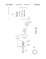
- FIG. 6 is a schematic view of the components of a composite key in accordance with the invention.
- FIG. 7 is a cross-sectional side elevation view of the portion of the key which is shown in FIG. 2;
- FIG. 8 is a bottom view of the apparatus depicted in FIG. 7;
- FIG. 9 is a diagram which represents the mode of operation of the command module of the composite key of the invention.
- a security system in accordance with a first embodiment of the present invention comprises a lock, indicated generally at 10 in FIG. 1, a cooperating "key”, shown partly and generally at 12 in FIG. 2, a control module, indicated generally at 14 in FIG. 1, an electronic command module, indicated generally at 54 in FIG. 6, and a device for periodically reactivating command module 54, indicated at 94 in FIG. 6.
- the control module 14 will be directly coupled to the lock 10, i.e., direct electrical connections for control signal and power transmission will be established in the manner depicted in FIG. 1.
- Control module 14 will be installed in the same equipment, a coin collection apparatus of some type for example, which houses the lock.
- a digitally coded identification signal will, in the disclosed embodiment, be generated by logic circuitry within control module 14 upon receipt of an interrogation command from command module 54 via key 12.
- the interrogation command may simply be the application of power to module 14.
- the identification signal will, when generated, be transmitted to the command module 54 via a conductive path established through the lock and key, i.e., the identification signal will be sent over the same path as the interrogation signal.
- the lock 10 is a modified version of a cylinder type lock which may, for example, be of the type disclosed in U.S. Pat. No. 4,823,575.
- the cylinder lock includes a plug 16 which is rotatable in a shell 18, the plug defining a keyway 20.
- the lock 10 may be "rekeyed" by replacement of the cylinder including the plug. The means by which such rekeying is accomplished is known in the art and has been omitted from the drawings in the interest of facilitating understanding of the invention.
- a tailpiece not shown, will customarily be mechanically coupled to the inwardly disposed end of the plug 16 for operating a bolt between the locked and retracted positions in response to rotation of plug 16 relative to shell 18.
- Rotation of plug 16 relative to shell 18 of lock 10 is accomplished by applying torque to a properly profiled and bitted blade 22 of a mechanical key which has been inserted into the keyway 20 in plug 16.
- the bitting on key blade 22 is in the form of a pattern of dimples of different size, depth and angular orientation in plural sides of the blade as shown in U.S. Pat. No. 4,823,575. These dimples cooperate with pin tumbler stacks housed in the shell and plug of lock 10 such that, when a properly bitted key blade is inserted into the keyway, the shear lines between the cooperating bottom and driver pin tumbler stacks will be in registration with a cylindrical interface between the plug and shell thus permitting plug rotation.
- the bitting on the key blade accordingly, comprises the first of a pair of coded input signals which are required to operate lock 10.
- the insertion of a properly bitted key blade into keyway 20 will not permit rotation of the plug 16 until at least one further pin tumbler stack, which may not be accessed via the keyway 20, has been displaced.
- the above-mentioned further pin tumbler stack provided within lock 10 includes a spring biased bottom pin 24, which may be seen from FIG. 5, and a cooperating driver pin 26.
- Bottom pin 24 is biased, by means of a spring 28, so as to normally extend across a shear line between plug 16 and shell 18 thus preventing plug rotation.
- the pin chamber in the lock which accommodates the tumbler stack 24, 26 does not communicate with keyway 20.
- An extension of driver pin 26 is at least in part comprised of magnetic material and forms the plunger of a push-type solenoid 30. Bottom pin 24 will be pushed, against the bias of spring 28, into a receiving bore provided therefor in plug 16, i.e., to the position shown in FIGS.
- FIG. 5A schematically shows pin 26 in the solenoid deenergized position corresponding to the locked state.
- FIGS. 4 and 5B show pin 24 in the depressed position resulting from the force provided by energizing solenoid 30, the motion of solenoid plunger being delivered to pin 24 by driver pin 26.
- the outer end of bottom pin 24 will ride on an inside diameter of shell 18 of lock 10 during rotation of plug 16 in response to the application of torque to key blade 22 after energization of solenoid 30.
- the solenoid 30 is mounted in a holder 32 which, in turn, is received in a two piece housing indicated generally at 34 in FIG. 2.
- Housing 34 is defined by upper and lower clamp members 36 and 38 which may be fitted over holder 32 and snapped together.
- An outer shell 40 of the cylinder lock is provided with slots which receive locating projections 42 on clamp members 36 and 38, the cooperation between the slots and projections insuring proper positioning of the solenoid relative to the cylinder lock.
- the solenoid 30 may be energized after full insertion of the key blade 22 into keyway 20.
- the energization of solenoid 30 needs to be only momentarily, i.e., once the plug 16 has been rotated a few degrees from the locked position the bottom pin 24 can not extend across the shear line until the plug is returned to the angular orientation commensurate with the locked condition.
- lock 10 may be operated from the locked to the unlocked condition only in response to simultaneous application of a pair of signals.
- the first of these signals is mechanically formatted, i.e., the first signal comprises the cross-sectional shape of and bitting provided on the key blade 22, while the second signal is electrically produced in the manner to be described below.
- the second signal will cause energization of solenoid 30 to displace the pin tumbler stack which includes bottom pin 24 whereby torque which is being applied to the blade 22 of a properly bitted key at the time of solenoid energization will cause rotation of the plug 16 relative to shell 18.
- the control module 14 includes electronics in the form of a microprocessor 45, with associated memory 44, and a microprocessor controlled solid state switch 46 for energizing solenoid 30 via conductors 47.
- the memory 44 associated with microprocessor 45 will store a multi-digit identification code which is unique to the lock. All power required for operation of microprocessor 45 and solenoid 30, will be provided from an external source associated with command module 54.
- control module 14 When interrogated by an external signal, i.e., when activated by the delivery of power thereto through key 12, control module 14 will generate a pulse train commensurate with its digitally encoded identification number. This coded signal will be transmitted, via key 12, to the command module 54 where it will be compared with a stored identification code. If there is a "match”, an energization command signal will be generated by command module 54 and this command signal will be transmitted back to microprocessor 44 via the key. Microprocessor 44 will, in response to receipt of a proper command, cause the solid state switch 46 to be "closed”. The closing of switch 46 will establish a current flow path which includes the coil of solenoid 30 thereby energizing the solenoid and displacing the pin tumbler stack 24, 26 against the bias of spring 28 as described above.
- key 12 is provided with a jack 50 having a plurality of contacts. Jack 50 will be coupled, via a plug on the end of a cable 52, to command module 54 (FIG. 6).
- command module 54 includes a microprocessor, a clock and associated communications circuitry.
- the command module 54 also includes a rechargable battery pack 56. In the typical use enironment, the command module 54 will be carried by a first security officer while the mechanical key 12 will be carried by a second security officer.
- key 12 includes a matable combination of a mechanical key, comprising blade 22 and a bow portion 60, and an electrically insulated key holder 62.
- the key holder 62 is defined by a pair of molded plastic members 64 and 66 which are provided with recesses in the facing sides thereof. These recesses are sized and shaped to define a receiver for the bow 60 of the mechanical portion of the composite key.
- the key holder 62 is provided with a first spring loaded contact pin 68 which cooperates with a contact ring 70 provided at the front of lock 10.
- Contact ring 70 as best seen from FIG. 4, is received in an annular recess of a collar 72.
- Collar 72 is comprised of a non-conductive material and, accordingly, ring 70 is electrically insulated from the lock.
- the contact ring 70 is connected, via an insulated conductor 74 which extends through a bore provided therefore in collar 72, to control module 14.
- pin 68 is electrically connected to a first conductor of cable 52 via a conductive spring 76, wire 77 and jack 50 as shown in FIG. 7.
- pin 68 will be urged against contact ring 70 by biasing spring 76 thus insuring a good electrical contact between the pin and ring.
- the bow 60 of the mechanical key is sandwiched in key holder 62 in such a manner as to insure establishment of electrical contact between the electrically conductive key and a terminal 78 provided on holder defining member 64.
- Terminal 78 is electrically connected to jack 50 via wire 79 and, via jack 50, to a second conductor of cable 52.
- control module 14 when the plug on the end of cable 52 is inserted in jack 50 and the key blade 22 has been inserted in the keyway 20 in plug 16, and provided that the command module has been reactivated within a predetermined preceding time period in the manner to be described below, the control module 14 will be energized, i.e., interrupted, and the identification code of lock system 10 will be read from memory 44 by microprocessor 45 and transmitted from control module 14 to command module 54. The transmitted data will be compared with data stored in module 54 and, in the manner described above, a "match" will result in generation of a command which will cause activation of switch 46.
- a key in accordance with the invention will also be provided with a second spring loaded contact pin 90 which is electrically connected via conductor 91 to a third contact in plug 50.
- the key will additionally have a fourth contact 92 which is electrically connected to terminal 78.
- Contacts 90 and 92 are spaced and shaped so as to cooperate with a touch memory 94 such as, for example, a semiconductor memory chip packaged in a coin shaped can.
- touch memories are available from Dallas Semi-Conductor and may, for example, be mounted on an identification card.
- a touch memory has the ability of reading or writing with a momentary contact and communicates to a host device via a single signal.
- the touch memory will respond with the programmed information.
- This programmed information may include the identification of the individual carrying the touch memory.
- the information read out of touch memory 94 will be transmitted to the microprocessor in command module 54 where a comparison will occur. If the information stored in the touch memory is commensurate with authorization to operate lock 10 and the read-out of memory 94 is "current", control module 14 may be interrogated in the manner described above.
- the read-out of touch memory 94 will start a timer in command module 54 and the command module will begin to "time-out". After the predetermined time out period, command module 54 will be disabled until such time as it is reactivated by again bringing touch memory 94 into contact with the key contacts 90 and 92.
- command module 54 must be activated in response to the code stored in touch memory 94 satisfying criteria stored in the memory of the command module.
- the code stored in control module 14 must also satisfy criteria stored in command module 54.
- the code on the blade 22 of key 12 must satisfy the criteria established by the pin tumbler stacks of lock 10. Lock 10 may not be operated without all three components, i.e., key, command module and touch memory being present and having stored therein proper code information.
- command module 54 The only subsystem of the lock control system which has a permanent power source is the command module 54.
- Command module 54 thus has the capability of collecting and storing data. This data may be periodically read out of the command module via a communications port and subsequently analyzed.
- the data collected in the memory of command module 54 will, in the typical use environment, include the time of each establishment of contact between the touch memory and key contacts and the identification of the particular touch memory.
- the command module may also store information commensurate with the code transmitted by control module 14 immediately prior to each energization of solenoid 30 and the time of such code transmission. Thus, a record will be created detailing each attempt to gain access to the interior of the equipment protected by lock 10.
- control module 14 Since the equipment in which the lock 10 is installed will typically have a power source, it is also possible to have the memory 44 of control module 14 permanently enabled to receive data.
- a sensor 100 may be provided on the machine and provide data commensurate with machine operation to memory 44. This information may be read from memory 44 into the memory of command module 54 in response to each solenoid energization command signal.
- the command module 54 may perform a secondary function of collecting data for inventory control, history of openings, or other purposes.
Abstract
Description
Claims (17)
Priority Applications (2)
| Application Number | Priority Date | Filing Date | Title |
|---|---|---|---|
| US08/483,277 US5771722A (en) | 1993-11-12 | 1995-06-07 | Dual control mode lock system |
| CA 2178427 CA2178427A1 (en) | 1995-06-07 | 1996-06-06 | Dual control mode lock system |
Applications Claiming Priority (2)
| Application Number | Priority Date | Filing Date | Title |
|---|---|---|---|
| US08/152,220 US5423198A (en) | 1993-11-12 | 1993-11-12 | Dual control mode lock |
| US08/483,277 US5771722A (en) | 1993-11-12 | 1995-06-07 | Dual control mode lock system |
Related Parent Applications (1)
| Application Number | Title | Priority Date | Filing Date |
|---|---|---|---|
| US08/152,220 Continuation-In-Part US5423198A (en) | 1993-11-12 | 1993-11-12 | Dual control mode lock |
Publications (1)
| Publication Number | Publication Date |
|---|---|
| US5771722A true US5771722A (en) | 1998-06-30 |
Family
ID=46202715
Family Applications (1)
| Application Number | Title | Priority Date | Filing Date |
|---|---|---|---|
| US08/483,277 Expired - Fee Related US5771722A (en) | 1993-11-12 | 1995-06-07 | Dual control mode lock system |
Country Status (1)
| Country | Link |
|---|---|
| US (1) | US5771722A (en) |
Cited By (31)
| Publication number | Priority date | Publication date | Assignee | Title |
|---|---|---|---|---|
| US6085560A (en) * | 1998-10-16 | 2000-07-11 | Compx International, Inc. | Axial pin tumbler lock with electronic features |
| US6442986B1 (en) | 1998-04-07 | 2002-09-03 | Best Lock Corporation | Electronic token and lock core |
| EP1264060A2 (en) * | 1999-12-08 | 2002-12-11 | Winfield Locks, Inc., doing business as Computerized Security Systems | Electronic lock |
| US6609402B2 (en) * | 2000-04-06 | 2003-08-26 | Schlage Lock Company | Electronic key assembly with spring loaded data pin and contact |
| DE20308813U1 (en) * | 2003-06-05 | 2004-10-14 | Harting Electro-Optics Gmbh & Co. Kg | Key for lock system has metal plates in lock cylinder that oppose metal plates in chip holder part for electronic chip with plug-in part inserted to form capacitor |
| US20050127090A1 (en) * | 2003-12-16 | 2005-06-16 | Sayers Richard C. | Electronically keyed dispensing systems and related methods of installation and use |
| US6927670B1 (en) * | 1992-02-14 | 2005-08-09 | Security People, Inc. | Conventional mechanical lock cylinders and keys with electronic access control feature |
| US20050285716A1 (en) * | 2001-12-27 | 2005-12-29 | Triteq Lock And Security, Llc | Electronic key control and management system for vending machines and the like |
| US20060048552A1 (en) * | 2003-02-19 | 2006-03-09 | San Jose Santamarta Ignacio A | Rotary locking mechanism,which is preferably intended for lock cylinders |
| US20070007114A1 (en) * | 2005-07-07 | 2007-01-11 | Liu Calvin Y | Reset lock for electronic devices |
| US20070096871A1 (en) * | 2005-10-28 | 2007-05-03 | Mason David M | Visitor pass for devices or for networks |
| US20070225078A1 (en) * | 2006-03-23 | 2007-09-27 | Wms Gaming Inc. | Gaming machine with modular actuator for remote door latch |
| US7397343B1 (en) * | 1992-02-14 | 2008-07-08 | Security People, Inc. | Conventional mechanical lock cylinders and keys with electronic access control feature |
| EP1980693A2 (en) * | 2007-04-12 | 2008-10-15 | ASSA ABLOY Sicherheitstechnik GmbH | Cylinder lock |
| WO2009109972A1 (en) * | 2008-03-05 | 2009-09-11 | Knock N'lock Ltd. | Cam lock |
| US7621426B2 (en) | 2004-12-15 | 2009-11-24 | Joseph Kanfer | Electronically keyed dispensing systems and related methods utilizing near field frequency response |
| EP2141663A2 (en) | 2008-06-30 | 2010-01-06 | Trell, Anders Edvard | Method for credentialing mechanical keys and associated devices |
| US20100077809A1 (en) * | 2008-09-30 | 2010-04-01 | Honeywell International Inc. | Method for identifying keys for controlling locks |
| US20100139340A1 (en) * | 2008-12-04 | 2010-06-10 | Honeywell International Inc. | Lock-bumping and lock-picking detection |
| US20100231350A1 (en) * | 2007-10-18 | 2010-09-16 | Alexander Scharer | Mechatronic furniture lock |
| US20120324969A1 (en) * | 2010-01-25 | 2012-12-27 | Knock N'lock Ltd. | Door cylinder lock |
| US8643487B2 (en) | 2003-12-11 | 2014-02-04 | Triteq Lock And Security, Llc | Electronic security system for monitoring mechanical keys and other items |
| US8640513B2 (en) * | 2011-06-22 | 2014-02-04 | The Stanley Works Israel Ltd. | Electronic and manual lock assembly |
| US8640514B2 (en) | 2011-06-22 | 2014-02-04 | The Stanley Works Israel Ltd. | Electronic and manual lock assembly |
| US9003845B2 (en) | 2002-01-03 | 2015-04-14 | Master Lock Company Llc | Lock apparatus and method |
| USRE45627E1 (en) | 2004-04-01 | 2015-07-28 | Kwikset Corporation | Re-keyable lock cylinder |
| WO2015094555A3 (en) * | 2013-12-17 | 2015-09-03 | Brady Worldwide, Inc. | Enclosure assembly for securing a door |
| US10269202B2 (en) | 2001-12-27 | 2019-04-23 | Mobile Tech, Inc. | Intelligent key system |
| US10403122B2 (en) | 2005-12-23 | 2019-09-03 | Invue Security Products Inc. | Programmable security system and method for protecting merchandise |
| US10540872B2 (en) | 2016-04-15 | 2020-01-21 | Mobile Tech, Inc. | Gateway-based anti-theft security system and method |
| US11709164B2 (en) | 2017-10-26 | 2023-07-25 | National University Of Singapore | Approach for universal monitoring of minimal residual disease in acute myeloid leukemia |
Citations (22)
| Publication number | Priority date | Publication date | Assignee | Title |
|---|---|---|---|---|
| FR2518618A1 (en) * | 1981-12-17 | 1983-06-24 | Laperche Sa | Key-operated electronic lock e.g. for hotel - checks pulse code transmitted between key and lock using microprocessor comparator circuit to allow release of locking bolt |
| US4603564A (en) * | 1981-06-17 | 1986-08-05 | Bauer Kaba Ag | Lock cylinder with integrated electromagnetic locking system |
| WO1987000234A1 (en) * | 1985-07-01 | 1987-01-15 | Ab Volvo | Electronic locking system |
| US4658105A (en) * | 1984-08-10 | 1987-04-14 | Bauer Kaba Ag | Electrical contact means for a lock cylinder with an electronic/mechanical key |
| US4686358A (en) * | 1984-03-15 | 1987-08-11 | Bauer Kaba Ag | Programmable electronic-mechanical reversing flat key interactively communicatable with data processing means |
| WO1988000635A1 (en) * | 1986-07-14 | 1988-01-28 | Lowe & Fletcher Limited | Information carrier and reader and method of verifying key |
| US4730471A (en) * | 1985-10-24 | 1988-03-15 | Bauer Kaba Ag | Apparatus for electromagnetic locking on a lock cylinder for a mechanical/electronic locking system |
| US4745785A (en) * | 1985-06-12 | 1988-05-24 | Bauer Kaba Ag | Manually or electrically driven lock |
| US4761976A (en) * | 1982-11-26 | 1988-08-09 | Bauer Kaba Ag | Lock cylinder with integrated electromagnetic locking mechanism |
| US4771620A (en) * | 1985-12-19 | 1988-09-20 | Bauer Kaba Ag | Locking device for a mechanical-electronic locking apparatus |
| US4789859A (en) * | 1986-03-21 | 1988-12-06 | Emhart Industries, Inc. | Electronic locking system and key therefor |
| US4848115A (en) * | 1986-03-21 | 1989-07-18 | Emhart Industries, Inc. | Electronic locking system and key therefor |
| US4854146A (en) * | 1985-10-25 | 1989-08-08 | Lowe And Fletcher Limited | Security device and method |
| US4858453A (en) * | 1986-12-06 | 1989-08-22 | Kokusan Kinzoku Kogyo Kabushiki Kaisha | Car anti-theft device |
| EP0329931A2 (en) * | 1988-02-22 | 1989-08-30 | BKS GmbH | Electromechanically operated door-locking apparatus |
| US4868409A (en) * | 1986-11-14 | 1989-09-19 | Honda Giken Kogyo K.K. | Vehicular anti-theft system |
| US4939915A (en) * | 1987-02-09 | 1990-07-10 | R. Berchtold Ag | Electromechanical locking device |
| US4998952A (en) * | 1990-03-02 | 1991-03-12 | Medeco Security Locks, Inc. | Key for electronic and mechanical locks |
| US5140317A (en) * | 1990-05-11 | 1992-08-18 | Medeco Security Locks, Inc. | Electronic security system |
| JPH05141139A (en) * | 1991-11-19 | 1993-06-08 | J Ii L:Kk | Locking device and writing device used therefor |
| US5373718A (en) * | 1992-03-06 | 1994-12-20 | Aug. Winkhaus Gmbh & Co. Kg | Electronic lock cylinder connectable by a plug connector |
| US5469727A (en) * | 1992-03-06 | 1995-11-28 | Aug.Winkhaus Gmbh & Co. Kg | Electronic lock cylinder |
-
1995
- 1995-06-07 US US08/483,277 patent/US5771722A/en not_active Expired - Fee Related
Patent Citations (22)
| Publication number | Priority date | Publication date | Assignee | Title |
|---|---|---|---|---|
| US4603564A (en) * | 1981-06-17 | 1986-08-05 | Bauer Kaba Ag | Lock cylinder with integrated electromagnetic locking system |
| FR2518618A1 (en) * | 1981-12-17 | 1983-06-24 | Laperche Sa | Key-operated electronic lock e.g. for hotel - checks pulse code transmitted between key and lock using microprocessor comparator circuit to allow release of locking bolt |
| US4761976A (en) * | 1982-11-26 | 1988-08-09 | Bauer Kaba Ag | Lock cylinder with integrated electromagnetic locking mechanism |
| US4686358A (en) * | 1984-03-15 | 1987-08-11 | Bauer Kaba Ag | Programmable electronic-mechanical reversing flat key interactively communicatable with data processing means |
| US4658105A (en) * | 1984-08-10 | 1987-04-14 | Bauer Kaba Ag | Electrical contact means for a lock cylinder with an electronic/mechanical key |
| US4745785A (en) * | 1985-06-12 | 1988-05-24 | Bauer Kaba Ag | Manually or electrically driven lock |
| WO1987000234A1 (en) * | 1985-07-01 | 1987-01-15 | Ab Volvo | Electronic locking system |
| US4730471A (en) * | 1985-10-24 | 1988-03-15 | Bauer Kaba Ag | Apparatus for electromagnetic locking on a lock cylinder for a mechanical/electronic locking system |
| US4854146A (en) * | 1985-10-25 | 1989-08-08 | Lowe And Fletcher Limited | Security device and method |
| US4771620A (en) * | 1985-12-19 | 1988-09-20 | Bauer Kaba Ag | Locking device for a mechanical-electronic locking apparatus |
| US4789859A (en) * | 1986-03-21 | 1988-12-06 | Emhart Industries, Inc. | Electronic locking system and key therefor |
| US4848115A (en) * | 1986-03-21 | 1989-07-18 | Emhart Industries, Inc. | Electronic locking system and key therefor |
| WO1988000635A1 (en) * | 1986-07-14 | 1988-01-28 | Lowe & Fletcher Limited | Information carrier and reader and method of verifying key |
| US4868409A (en) * | 1986-11-14 | 1989-09-19 | Honda Giken Kogyo K.K. | Vehicular anti-theft system |
| US4858453A (en) * | 1986-12-06 | 1989-08-22 | Kokusan Kinzoku Kogyo Kabushiki Kaisha | Car anti-theft device |
| US4939915A (en) * | 1987-02-09 | 1990-07-10 | R. Berchtold Ag | Electromechanical locking device |
| EP0329931A2 (en) * | 1988-02-22 | 1989-08-30 | BKS GmbH | Electromechanically operated door-locking apparatus |
| US4998952A (en) * | 1990-03-02 | 1991-03-12 | Medeco Security Locks, Inc. | Key for electronic and mechanical locks |
| US5140317A (en) * | 1990-05-11 | 1992-08-18 | Medeco Security Locks, Inc. | Electronic security system |
| JPH05141139A (en) * | 1991-11-19 | 1993-06-08 | J Ii L:Kk | Locking device and writing device used therefor |
| US5373718A (en) * | 1992-03-06 | 1994-12-20 | Aug. Winkhaus Gmbh & Co. Kg | Electronic lock cylinder connectable by a plug connector |
| US5469727A (en) * | 1992-03-06 | 1995-11-28 | Aug.Winkhaus Gmbh & Co. Kg | Electronic lock cylinder |
Cited By (56)
| Publication number | Priority date | Publication date | Assignee | Title |
|---|---|---|---|---|
| US6927670B1 (en) * | 1992-02-14 | 2005-08-09 | Security People, Inc. | Conventional mechanical lock cylinders and keys with electronic access control feature |
| US7397343B1 (en) * | 1992-02-14 | 2008-07-08 | Security People, Inc. | Conventional mechanical lock cylinders and keys with electronic access control feature |
| US6668606B1 (en) | 1998-04-07 | 2003-12-30 | Best Access Systems | Electronic token lock core |
| US6442986B1 (en) | 1998-04-07 | 2002-09-03 | Best Lock Corporation | Electronic token and lock core |
| US6085560A (en) * | 1998-10-16 | 2000-07-11 | Compx International, Inc. | Axial pin tumbler lock with electronic features |
| EP1264060A4 (en) * | 1999-12-08 | 2004-07-21 | Winfield Locks Inc Doing Busin | Electronic lock |
| EP1264060A2 (en) * | 1999-12-08 | 2002-12-11 | Winfield Locks, Inc., doing business as Computerized Security Systems | Electronic lock |
| US6609402B2 (en) * | 2000-04-06 | 2003-08-26 | Schlage Lock Company | Electronic key assembly with spring loaded data pin and contact |
| US10453291B2 (en) | 2001-12-27 | 2019-10-22 | Mobile Tech, Inc. | Intelligent key system |
| US10269202B2 (en) | 2001-12-27 | 2019-04-23 | Mobile Tech, Inc. | Intelligent key system |
| US20050285716A1 (en) * | 2001-12-27 | 2005-12-29 | Triteq Lock And Security, Llc | Electronic key control and management system for vending machines and the like |
| US10984625B2 (en) | 2001-12-27 | 2021-04-20 | Mobile Tech, Inc. | Intelligent key system |
| US20090051486A1 (en) * | 2001-12-27 | 2009-02-26 | Micro Enhanced Technologies, Inc | Electronic key control and management system for vending machines and the like |
| US9003845B2 (en) | 2002-01-03 | 2015-04-14 | Master Lock Company Llc | Lock apparatus and method |
| US7073359B2 (en) * | 2003-02-19 | 2006-07-11 | Tallers De Escoriaza, S.A. | Rotary locking mechanism, which is preferably intended for lock cylinders |
| US20060048552A1 (en) * | 2003-02-19 | 2006-03-09 | San Jose Santamarta Ignacio A | Rotary locking mechanism,which is preferably intended for lock cylinders |
| DE20308813U1 (en) * | 2003-06-05 | 2004-10-14 | Harting Electro-Optics Gmbh & Co. Kg | Key for lock system has metal plates in lock cylinder that oppose metal plates in chip holder part for electronic chip with plug-in part inserted to form capacitor |
| US8643487B2 (en) | 2003-12-11 | 2014-02-04 | Triteq Lock And Security, Llc | Electronic security system for monitoring mechanical keys and other items |
| US20050127090A1 (en) * | 2003-12-16 | 2005-06-16 | Sayers Richard C. | Electronically keyed dispensing systems and related methods of installation and use |
| US7028861B2 (en) | 2003-12-16 | 2006-04-18 | Joseph S. Kanfer | Electronically keyed dispensing systems and related methods of installation and use |
| US8009015B2 (en) | 2003-12-16 | 2011-08-30 | Joseph S. Kanfer | Electronically keyed dispensing systems and related methods of installation and use |
| USRE45627E1 (en) | 2004-04-01 | 2015-07-28 | Kwikset Corporation | Re-keyable lock cylinder |
| US7621426B2 (en) | 2004-12-15 | 2009-11-24 | Joseph Kanfer | Electronically keyed dispensing systems and related methods utilizing near field frequency response |
| US20090314799A1 (en) * | 2004-12-15 | 2009-12-24 | Kanfer, Joseph | Electronically keyed dispensing systems and related methods utilizing near field frequency response |
| US8783510B2 (en) | 2004-12-15 | 2014-07-22 | Joseph Kanfer | Electronically keyed dispensing systems and related methods utilizing near field frequency response |
| US7837066B2 (en) | 2004-12-15 | 2010-11-23 | Joseph Kanfer | Electronically keyed dispensing systems and related methods utilizing near field frequency response |
| US7408126B2 (en) * | 2005-07-07 | 2008-08-05 | Cisco Technology, Inc. | Reset lock for electronic devices |
| US20070007114A1 (en) * | 2005-07-07 | 2007-01-11 | Liu Calvin Y | Reset lock for electronic devices |
| US20070096871A1 (en) * | 2005-10-28 | 2007-05-03 | Mason David M | Visitor pass for devices or for networks |
| US11721198B2 (en) | 2005-12-23 | 2023-08-08 | Invue Security Products Inc. | Programmable security system and method for protecting merchandise |
| US10600313B2 (en) | 2005-12-23 | 2020-03-24 | Invue Security Products Inc. | Programmable security system and method for protecting merchandise |
| US10403122B2 (en) | 2005-12-23 | 2019-09-03 | Invue Security Products Inc. | Programmable security system and method for protecting merchandise |
| US20070225078A1 (en) * | 2006-03-23 | 2007-09-27 | Wms Gaming Inc. | Gaming machine with modular actuator for remote door latch |
| US7553237B2 (en) * | 2006-03-23 | 2009-06-30 | Wms Gaming Inc. | Gaming machine with modular actuator for remote door latch |
| EP1980693A2 (en) * | 2007-04-12 | 2008-10-15 | ASSA ABLOY Sicherheitstechnik GmbH | Cylinder lock |
| EP1980693A3 (en) * | 2007-04-12 | 2008-10-22 | ASSA ABLOY Sicherheitstechnik GmbH | Cylinder lock |
| US20100231350A1 (en) * | 2007-10-18 | 2010-09-16 | Alexander Scharer | Mechatronic furniture lock |
| CN102016203A (en) * | 2008-03-05 | 2011-04-13 | 诺克N′洛克有限公司 | Cam lock |
| US20110083482A1 (en) * | 2008-03-05 | 2011-04-14 | Knock N'lock Ltd. | Cam lock |
| CN102016203B (en) * | 2008-03-05 | 2013-11-27 | 诺克N’洛克有限公司 | Cam lock |
| WO2009109972A1 (en) * | 2008-03-05 | 2009-09-11 | Knock N'lock Ltd. | Cam lock |
| EP2141663A2 (en) | 2008-06-30 | 2010-01-06 | Trell, Anders Edvard | Method for credentialing mechanical keys and associated devices |
| US7941934B2 (en) * | 2008-09-30 | 2011-05-17 | Honeywell International Inc. | Method for identifying keys for controlling locks |
| US20100077809A1 (en) * | 2008-09-30 | 2010-04-01 | Honeywell International Inc. | Method for identifying keys for controlling locks |
| US20100139340A1 (en) * | 2008-12-04 | 2010-06-10 | Honeywell International Inc. | Lock-bumping and lock-picking detection |
| US7958647B2 (en) * | 2008-12-04 | 2011-06-14 | Honeywell International Inc. | Lock-bumping and lock-picking detection |
| US8544302B2 (en) * | 2010-01-25 | 2013-10-01 | Knock N'lock Ltd. | Door cylinder lock |
| US20120324969A1 (en) * | 2010-01-25 | 2012-12-27 | Knock N'lock Ltd. | Door cylinder lock |
| US8640513B2 (en) * | 2011-06-22 | 2014-02-04 | The Stanley Works Israel Ltd. | Electronic and manual lock assembly |
| US8640514B2 (en) | 2011-06-22 | 2014-02-04 | The Stanley Works Israel Ltd. | Electronic and manual lock assembly |
| US9466190B2 (en) | 2013-12-17 | 2016-10-11 | Brady Worldwide, Inc. | Enclosure assembly for securing a door |
| WO2015094555A3 (en) * | 2013-12-17 | 2015-09-03 | Brady Worldwide, Inc. | Enclosure assembly for securing a door |
| US10776473B2 (en) | 2016-04-15 | 2020-09-15 | Mobile Tech, Inc. | Authorization control for an anti-theft security system |
| US10540872B2 (en) | 2016-04-15 | 2020-01-21 | Mobile Tech, Inc. | Gateway-based anti-theft security system and method |
| US11315398B2 (en) | 2016-04-15 | 2022-04-26 | Mobile Tech, Inc. | Gateway-based anti-theft security system and method |
| US11709164B2 (en) | 2017-10-26 | 2023-07-25 | National University Of Singapore | Approach for universal monitoring of minimal residual disease in acute myeloid leukemia |
Similar Documents
| Publication | Publication Date | Title |
|---|---|---|
| US5771722A (en) | Dual control mode lock system | |
| US5423198A (en) | Dual control mode lock | |
| US6927670B1 (en) | Conventional mechanical lock cylinders and keys with electronic access control feature | |
| US7397343B1 (en) | Conventional mechanical lock cylinders and keys with electronic access control feature | |
| US8836474B2 (en) | Electronic access memory device and access point control | |
| US4789859A (en) | Electronic locking system and key therefor | |
| US6604394B2 (en) | Electronic locking system | |
| US4712398A (en) | Electronic locking system and key therefor | |
| US5628217A (en) | Electronic-mechanical locking cylinders | |
| US4848115A (en) | Electronic locking system and key therefor | |
| US5337588A (en) | Electronic lock and key system | |
| US6275141B1 (en) | Single-key security system | |
| EP1250505B1 (en) | Electronic locking system | |
| US5836187A (en) | Tumberless automobile ignition lock | |
| HU222702B1 (en) | Key and lock device | |
| KR20010040777A (en) | A radio frequency identification(rfid) security device | |
| CA2178427A1 (en) | Dual control mode lock system | |
| RU2740880C1 (en) | Locking system operation method and locking system for electromechanical lock devices | |
| RU2740833C2 (en) | Locking system operation method and locking system for electromechanical lock devices | |
| JPH0768805B2 (en) | Electronic key device | |
| CN214062620U (en) | Lock with immovable lock core capable of being used for additionally arranging electronic key for unlocking | |
| JPH10252327A (en) | Key system with id, night safe device, and rent safe system | |
| JPS62129478A (en) | Pulse system transmission lock system |
Legal Events
| Date | Code | Title | Description |
|---|---|---|---|
| AS | Assignment |
Owner name: KABA HIGH SECURITY LOCKS, INC., CONNECTICUT Free format text: ASSIGNMENT OF ASSIGNORS INTEREST;ASSIGNORS:DIVITO, THOMAS J.;HUMPHREY, EDWARD F.;REEL/FRAME:007529/0545 Effective date: 19950606 |
|
| FEPP | Fee payment procedure |
Free format text: PAYOR NUMBER ASSIGNED (ORIGINAL EVENT CODE: ASPN); ENTITY STATUS OF PATENT OWNER: LARGE ENTITY |
|
| FPAY | Fee payment |
Year of fee payment: 4 |
|
| AS | Assignment |
Owner name: UBS, AG ZURICH, SWITZERLAND Free format text: SECURITY AGREEMENT;ASSIGNORS:KABA CORPORATION;KABA ILCO CORPORATION;KABA HIGH SECURITY LOCKS CORPORATION;AND OTHERS;REEL/FRAME:012495/0716 Effective date: 20011001 |
|
| AS | Assignment |
Owner name: KABA CORPORATION, CONNECTICUT Free format text: RELEASE AND TERMINATION;ASSIGNOR:UBS AG, ZURICH;REEL/FRAME:015980/0516 Effective date: 20041102 Owner name: KABA ILCO CORPORATION, NORTH CAROLINA Free format text: RELEASE AND TERMINATION;ASSIGNOR:UBS AG, ZURICH;REEL/FRAME:015980/0516 Effective date: 20041102 Owner name: KABA HIGH SECURITY LOCKS CORPORATION, NORTH CAROLI Free format text: RELEASE AND TERMINATION;ASSIGNOR:UBS AG, ZURICH;REEL/FRAME:015980/0516 Effective date: 20041102 Owner name: ILCO UNICAN PROPERTIES, INC., NORTH CAROLINA Free format text: RELEASE AND TERMINATION;ASSIGNOR:UBS AG, ZURICH;REEL/FRAME:015980/0516 Effective date: 20041102 Owner name: KABA MAS CORPORATION, KENTUCKY Free format text: RELEASE AND TERMINATION;ASSIGNOR:UBS AG, ZURICH;REEL/FRAME:015980/0516 Effective date: 20041102 Owner name: KABA BENZING AMERICA, INC., FLORIDA Free format text: RELEASE AND TERMINATION;ASSIGNOR:UBS AG, ZURICH;REEL/FRAME:015980/0516 Effective date: 20041102 |
|
| REMI | Maintenance fee reminder mailed | ||
| LAPS | Lapse for failure to pay maintenance fees | ||
| STCH | Information on status: patent discontinuation |
Free format text: PATENT EXPIRED DUE TO NONPAYMENT OF MAINTENANCE FEES UNDER 37 CFR 1.362 |
|
| FP | Lapsed due to failure to pay maintenance fee |
Effective date: 20060630 |